

Operating Instructions
AV Control Receiver
Model No. SA-BX500
Dear customer
Thank you for purchasing this product.
Before connecting, operating or adjusting this product, please read
the instructions completely.
Please keep this manual for future reference.
As an ENERGY STAR Partner*,
Panasonic has determined that this
product meets the ENERGY STAR
guidelines for energy efficiency.
* For Canada only: The word “Participant” is used in place of
the word “Partner”.
If you have any questions, contact
In the U.S.A.: 1-800-211-PANA (7262)
In Canada: 1-800-561-5505
For U.S.A. only
The warranty can be found on page 57.
For Canada only
The warranty can be found on page 58.
PP
En
Cf
RQT9223-Y
H0608VC0
CAUTION
EST. 192 4
RISK OF ELECTRIC SHOCK
DO NOT OPEN
CAUTION: TO REDUCE THE RISK OF ELECTRIC
SHOCK, DO NOT REMOVE SCREWS.
NO USER-SERVICEABLE PARTS INSIDE.
REFER SERVICING TO QUALIFIED
SERVICE PERSONNEL.
The lightning flash with arrowhead symbol, within
an equilateral triangle, is intended to alert the user
to the presence of uninsulated “dangerous voltage”
within the product’s enclosure that may be of
sufficient magnitude to constitute a risk of electric
shock to persons.
The exclamation point within an equilateral triangle
is intended to alert the user to the presence of
important operating and maintenance (servicing)
instructions in the literature accompanying the
appliance.
CAUTION!
Do not place anything on top of this unit or block the heat radiation
vents in any way. In particular, do not place DVD recorder or CD/
DVD players on this unit as heat radiated from it can damage your
software.
CAUTION
Danger of explosion if battery is incorrectly replaced. Replace only
with the same or equivalent type recommended by the manufacturer.
Dispose of used batteries according to the manufacturer’s instructions.
WARNING:
TO REDUCE THE RISK OF FIRE, ELECTRIC SHOCK OR
PRODUCT DAMAGE,
DO NOT EXPOSE THIS APPARATUS TO RAIN,
*
MOISTURE, DRIPPING OR SPLASHING AND THAT NO
OBJECTS FILLED WITH LIQUIDS, SUCH AS VASES,
SHALL BE PLACED ON THE APPARATUS.
USE ONLY THE RECOMMENDED ACCESSORIES.
*
DO NOT REMOVE THE COVER (OR BACK); THERE
*
ARE NO USER SERVICEABLE PARTS INSIDE. REFER
SERVICING TO QUALIFIED SERVICE PERSONNEL.
CAUTION!
DO NOT INSTALL OR PLACE THIS UNIT IN A
BOOKCASE, BUILT-IN CABINET OR IN ANOTHER
CONFINED SPACE. ENSURE THE UNIT IS WELL
VENTILATED. TO PREVENT RISK OF ELECTRIC SHOCK
OR FIRE HAZARD DUE TO OVERHEATING, ENSURE
THAT CURTAINS AND ANY OTHER MATERIALS DO
NOT OBSTRUCT THE VENTILATION VENTS.
The socket outlet shall be installed near the equipment and easily
accessible.
The mains plug of the power supply cord shall remain readily
operable.
To completely disconnect this apparatus from the AC Mains,
disconnect the power supply cord plug from AC receptacle.
HDMI, the HDMI logo and High-Definition Multimedia
Interface are trademarks or registered trademarks of HDMI
Licensing LLC.
HDAVI Control™ is a trademark of Matsushita Electric
Industrial Co., Ltd.
RQT9223
Listening caution
Selecting fine audio equipment such as the unit you’ve just purchased is
the start of your musical enjoyment. Now it’s time to consider how
only
you can maximize the fun and excitement your equipment offers. This
manufacturer and the Electronic Industries Association’s Consumer
Electronics Group want you to get the most out of your equipment by
playing it at a safe level. One that lets the sound come through loud and
clear without annoying blaring or distortion-and, most importantly,
without affecting your sensitive hearing.
We recommend that you avoid prolonged exposure to excessive noise.
Sound can be deceiving. Over time your hearing “comfort level” adapts
to higher volumes of sound. So what sounds “normal” can actually be
loud and harmful to your hearing.
Guard against this by setting your equipment at a safe level BEFORE
your hearing adapts.
To establish a safe level:
Start your volume control at a low setting.
•
Slowly increase the sound until you can hear it comfortably and
•
clearly, and without distortion.
Once you have established a comfortable sound level:
Set the dial and leave it there.
•
Taking a minute to do this now will help to prevent hearing damage or
loss in the future. After all, we want you listening for a lifetime.
2
EZ Sync™ is a trademark of Matsushita Electric Industrial
Co., Ltd.
VIERA Link™ is a trademark of Matsushita Electric Industrial
Co., Ltd.
Manufactured under license from Dolby Laboratories.
Dolby, Pro Logic, and the double-D symbol are trademarks of
Dolby Laboratories.
Manufactured under license under U.S. Patent #’s: 5,451,942;
5,956,674; 5,974,380; 5,978,762; 6,226,616; 6,487,535 &
other U.S. and worldwide patents issued & pending. DTS is
a registered trademark and the DTS logos, Symbol, DTS-HD
and DTS-HD Master Audio are trademarks of DTS, Inc.
© 1996-2007 DTS, Inc. All Rights Reserved.
THE FOLLOWING APPLIES ONLY IN CANADA.
This device complies with RSS-210 of the IC Rules.
Operation is subject to the following two conditions:
(1) This device may not cause harmful interference,
(2) This device must accept any interference received,
including interference that may cause undesired operation of
the device.
-If you see this symbol-
Information on Disposal in other Countries outside the
European Union
This symbol is only valid in the European Union.
If you wish to discard this product, please contact your
local authorities or dealer and ask for the correct
method of disposal.

IMPORTANT SAFETY INSTRUCTIONS
Read these operating instructions carefully before using the unit. Follow the safety instructions on the unit and the applicable
safety instructions listed below. Keep these operating instructions handy for future reference.
10)
1) Read these instructions.
2) Keep these instructions.
Protect the power cord from being walked on or pinched
particularly at plugs, convenience receptacles, and the
point where they exit from the apparatus.
Before use
3) Heed all warnings.
4) Follow all instructions.
5) Do not use this apparatus near water.
6) Clean only with dry cloth.
7) Do not block any ventilation openings. Install in accordance
with the manufacturer’s instructions.
8) Do not install near any heat sources such as radiators, heat
registers, stoves, or other apparatus (including amplifiers)
that produce heat.
9)
Do not defeat the safety purpose of the polarized or
grounding-type plug. A polarized plug has two blades with
one wider than the other. A grounding-type plug has two
blades and a third grounding prong. The wide blade or the
third prong are provided for your safety. If the provided
plug does not fit into your outlet, consult an electrician for
replacement of the obsolete outlet.
THE FOLLOWING APPLIES ONLY IN THE U.S.A.
11) Only use attachments/accessories specified by the
manufacturer.
12) Use only with the cart, stand, tripod,
bracket, or table specified by the
manufacturer, or sold with the apparatus.
When a cart is used, use caution when
moving the cart/apparatus combination to
avoid injury from tip-over.
13) Unplug this apparatus during lightning storms or when
unused for long periods of time.
14) Refer all servicing to qualified service personnel. Servicing
is required when the apparatus has been damaged in any
way, such as power-supply cord or plug is damaged, liquid
has been spilled or objects have fallen into the apparatus,
the apparatus has been exposed to rain or moisture, does
not operate normally, or has been dropped.
FCC Note:
This equipment has been tested and found to comply with the limits for a Class B digital device, pursuant to Part 15 of the FCC
Rules.
These limits are designed to provide reasonable protection against harmful interference in a residential installation. This equipment
generates, uses and can radiate radio frequency energy and, if not installed and used in accordance with the instructions, may
cause harmful interference to radio communications.
H
owever, there is no guarantee that interference will not occur in a particular installation. If this equipment does cause harmful
interference to radio or television reception, which can be determined by turning the equipment off and on, the user is encouraged
to try to correct the interference by one or more of the following measures:
*
Reorient or relocate the receiving antenna.
*
Increase the separation between the equipment and receiver.
*
Connect the equipment into an outlet on a circuit different from that to which the receiver is connected.
*
Consult the dealer or an experienced radio/TV technician for help.
Listening caution / IMPORTANT SAFETY INSTRUCTIONS
FCC caution: To maintain compliance with FCC regulations, shielded interface cables must be used with this equipment.
Operation with non-approved equipment or unshielded cables may result in interference to radio and TV reception. Any changes
or modifications not approved by the party responsible for compliance could void the user’s authority to operate this equipment.
This device complies with Part 15 of the FCC Rules.
Operation is subject to the following two conditions:
(1) This device may not cause harmful interference, and
(2) this device must accept any interference received, including interference that may cause undesired operation.
Responsible Party:
Panasonic Corporation of North America
One Panasonic Way
Secaucus, NJ 07094
Support Contact:
Panasonic Consumer Electronics Company
Telephone No.: 1-800-211-PANA (7262)
3
RQT9223
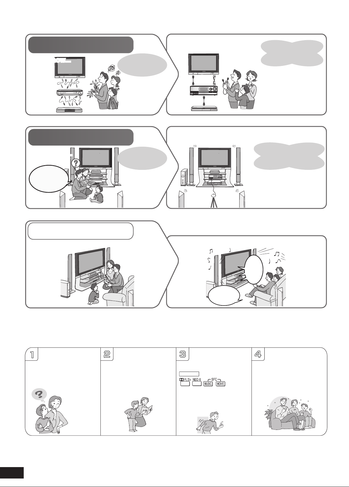
Enjoying the Home Theater has become easy!
Connections
Settings
With SA-BX500!With SA-BX500!
With SA-BX500!
With SA-BX500!
Many different
cables were
necessary.
Previous Home Theater systems required multiple
operations.
VIERA Link
When you connect the unit to your TV (VIERA) and DVD
recorder (DIGA) compatible with VIERA Link
Until now...Until now...
A B
The
Home
Theater
begins.
1
2 3 4
SURROUND
Simple connections
using 2 HDMI cables
and 1 stereo connection
cab
le!
Other connections are also
∗
le.
possib
A
utomatic speaker setup
Until now…
We must adjust the
speaker settings...
Manual setting for
each speaker.
is the easiest way to adjust
the speaker settings
(➔ pages 24, 25).
Enjoy the full surround sound from all speakers connected!!
How can we enjoy
TV with surround
sound?
Connections
and settings
are all
complete
2-channel stereo sounds
and only front speakers
are reproducing stereo
.
TV outputs
audio output.
Press just one button and enjoy the Home Theater effect
(➔ pages 32, 33).
One-touch
playback.
Just press
on the unit
on the
remote control
to enjoy surround sound
(➔ pa
ges 28, 29).
Great!! We can enjoy
TV with surround
sound.
RQT9223
4
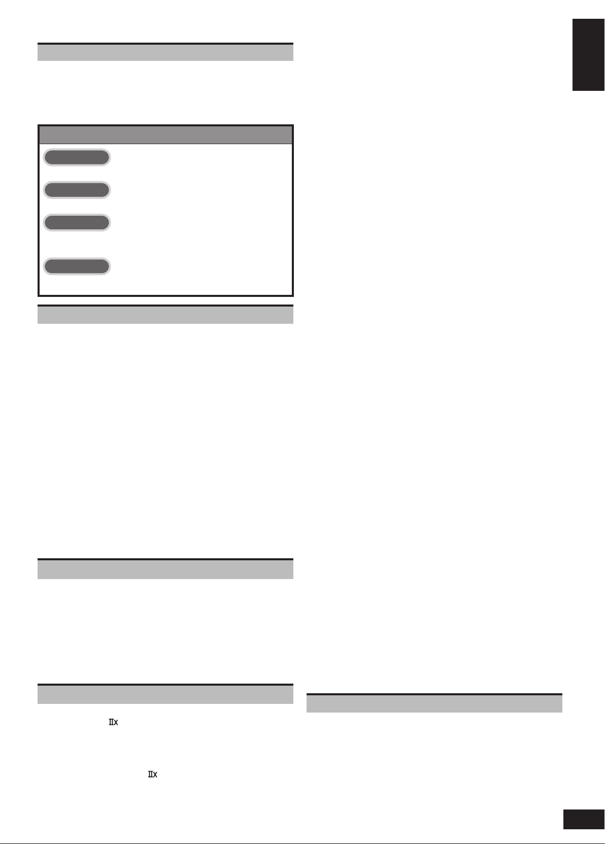
Table of contents
Before use
Listening caution ............................................................................2
IMPORTANT SAFETY INSTRUCTIONS ..........................................3
Enjo
ying the Home Theater has become easy! .............................4
Supplied
Contr
accessories .....................................................................6
ol guide ...................................................................................6
Quick guide
Step 1
Placing speakers ................................................................9
Step 2
Connecting speakers .......................................................10
Step 3
Connecting a TV and a
Blu-ray Disc/DVD player ................................................... 12
Step 4
Watching TV or DVD ..........................................................14
Preparations
Connections ......................................................................... 16
Basic connections ........................................................................16
Connecting equipment with HDMI terminal ..................................16
Connecting
(Connecting
Connecting cables to S video and audio terminals ....................18
Connecting
audio
Other connections ........................................................................20
T
o enjoy analog sounds ................................................................20
T
o enjoy high-quality analog sounds
(Analog
To connect the unit to a CD player. ................................................20
T
o connect the unit for audio or picture recording ..........................21
T
o connect the unit to a video camera etc. ....................................21
Connecting
T
o connect bi-wire speakers .........................................................22
To connect a second pair of front speakers (SPEAKERS B)
To enjoy wireless audio with SH-FX67 ..........................................23
Connecting
Auto speaker setup using the setup microphone
cables to video and audio terminals
equipment without HDMI terminal) ...........................17
cables to component and
terminals .............................................................................19
8-channel connections) ...................................................20
other speakers ..........................................................22
..............22
antennas ...................................................................23
..................... 24
Basic operations
Enjoying the Home Theater ................................................. 26
Basic playback ..............................................................................26
Using surround speakers wirelessly with SH-FX67 ...................27
T
o enjoy 7.1 channel playback using 2 sets of SH-FX67 ...............27
When you use wireless speakers in another room (MULTI ROOM)
Using SPEAKERS B ......................................................................27
Pla
yback when making analog 8-channel connections .............27
Enjo
ying only with TV speaker .....................................................27
Enjo
ying 7.1-channel virtual surround playback ........................27
....27
Operations
Listening to surround sound .............................................. 28
Dolby Pro Logic .......................................................................28
NEO:6 .............................................................................................28
SFC
(Sound Field Control) ...........................................................28
Sound
field ...................................................................................29
Remote controlling sound effects ...................................... 30
Adjusting Dolby Pro Logic ’s “MUSIC ” mode ......................... 30
Adjusting NEO:6’s “MUSIC ” mode ..............................................30
Convenient functions .......................................................... 31
Adjusting speaker volumes .........................................................31
Silencing speakers temporarily ...................................................31
Displa
ying the current status .......................................................31
Using the VIERA Link “HDAVI ControlTM” ........................... 32
Enjoying the Home Theater through one-touch operations ......33
Using the sound menu ........................................................ 34
Adjusting the speaker level .......................................................... 34
Adjusting the bass ........................................................................34
Adjusting
Balancing
Changing
Listening
Using
the treble ......................................................................34
front speaker volume ..................................................35
the audio output (Dual program) ................................35
clearly at low volume ....................................................35
whisper mode surround ....................................................35
Using the setup menu .......................................................... 36
Basic operation .............................................................................36
Adjusting the brightness of the display ......................................37
Using
sleep timer ..........................................................................37
Setting
speakers and their sizes .................................................. 37
Setting
distances ..........................................................................37
Setting
the lowpass filter ..............................................................38
Changing
T
Setting
Adjusting
response ......................................................................................38
Making
Setting
Changing
Setting
Setting
Setting
Adjusting
Reducing
(po
Setting VIERA Link to “OFF ”
Switching the attenuator ..............................................................40
Adjusting
output
Changing the volume display ......................................................40
Reset
auto speaker settings .................................................38
o return speakers to factory settings ...........................................38
the unit against automatic polarity adjustment ..................38
the high-frequency sound quality of the set frequency
bi-wire setting ..................................................................38
the speaker impedance ...................................................38
the input settings .........................................................39
the placement positions for surround speakers ............39
wireless speakers ............................................................39
input signals .....................................................................39
input levels for external terminals ..............................39
standby power consumption
wer save mode) ........................................................................40
........................................................40
the time lag by delaying audio
when pictures on TV arrives after sounds .......................40
(factory settings) ................................................................40
Using headphones ............................................................... 41
Recording ............................................................................. 41
Remote controlling a TV or DVD recorder etc
Remote controlling a TV, cable box and satellite receiver
Using two or more Panasonic equipment
(a
mini component system, an AV amp etc.) ...............................42
Remote controlling a DVD recorder .............................................43
Remote
Entering
controlling a Blu-ray Disc/DVD player ...........................44
a code to operate other equipment ..............................45
. ...................... 42
...............42
Playing an iPod on this unit ................................................. 47
Playing music recorded on iPod ..................................................47
Listening to the Radio ......................................................... 48
Preset tuning .................................................................................48
Auto presetting .............................................................................48
Man
ual presetting .........................................................................48
Listening
Man
T
uning directly using the numbered buttons ..................................49
Using
Using
Reducing
FM
to preset stations (using the remote control) ..................48
ual tuning ................................................................................49
the unit ................................................................................49
the remote control ...............................................................49
excessive noise ...........................................................49
frequency step ........................................................................49
Reference
Other information ................................................................ 50
Glossary ............................................................................... 52
Err
or messages .................................................................... 53
T
roubleshooting guide ........................................................ 54
Maintenance ......................................................................... 55
Specifications
Limited
Limited
Pr
oduct Service ................................................................... 59
...................................................................... 56
Warranty (Only for the U.S.A.) ................................ 57
Warranty (Only for Canada) ................................... 58
Before use
Enjoying the Home Theater has become easy! / Table of contents
5
RQT9223
Supplied accessories
WIRELESS READY
SURROUND M.ROOM
INPUT SELECTOR
VOLUME
+
_
MULTI CH
PROCESSING
TrueHD
D+
DTS-HD
MULTI CH
LPCM
BI-AMP
SETUP MIC
AUX
TUNE
RETURN
AUTO SPEAKER SETUP
-
SETUP
OK
SURROUND
SPEAKERS A
SPEAKERS B
S VIDEO
VIDEO
L - AUDIO - R
POWER
A B
2CH MIX
SPEAKERS
BI-WIRE
TUNED
MONO
SLEEP
ST
PCM
DTS 96/24DTS
-ES
DIGITAL EX
EX
M
DIGITAL INPUT
kHz
MHz
ft
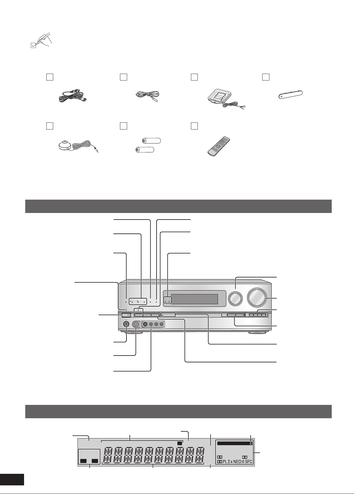
Please check and identify the supplied accessories.
Use numbers indicated in parentheses when asking for replacement parts.
(Product numbers correct as of June 2008. These may be subject to change.)
Only for the U.S.A.: To order accessories, refer to “Accessory Purchases” on page 57.
Only for Canada: To order accessories, call the dealer from whom you have made your purchase.
1 AC power supply cord
(K2CB2CB00021)
1 Setup micr
(L0CBAB000128)
ophone
1 FM indoor antenna
(RSA0007-M)
2 Batteries 1 Remote contr
1 AM loop antenna
AAAA00002)
(N1D
(N2QAKB000069)
ol
1 Front terminal cover
(RGK2137A-K)
(Canada only)
The enclosed Canadian French label sheet corresponds to the English display on the front and back sides of the unit.
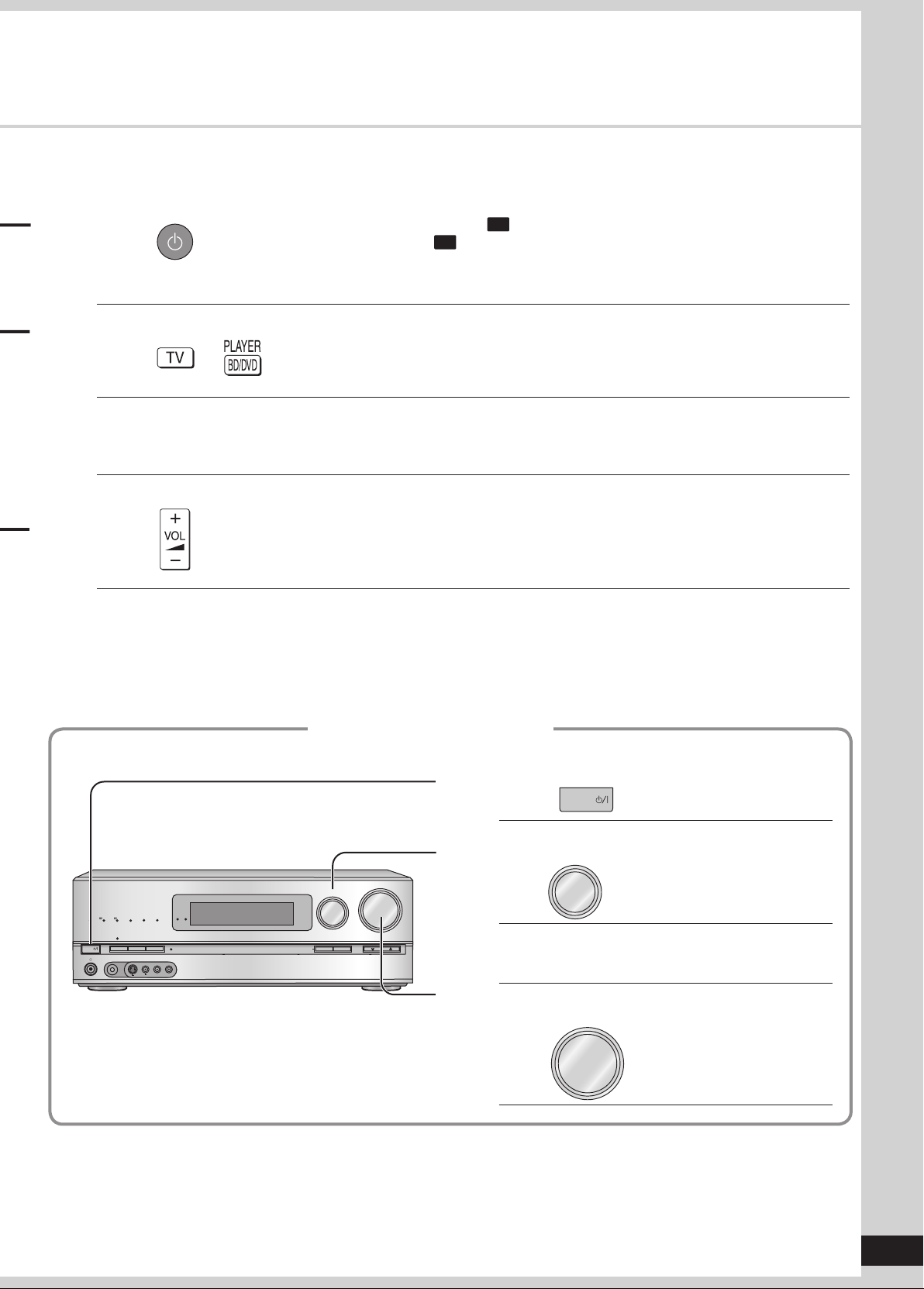
Control guide
This unit
Lights on when playing a disc using
multi-channel LPCM format
Lights on when playing a disc using
high definition audio format such as
Blu-ray Disc
Lights on when the following multichannel playback settings are used
• When pla
• When using surround eff
ying multi-channel sources
ects for two-
channel sources, etc.
Standby indicator [^]
When the unit is connected to the
household A
C outlet, this indicator lights
up in standby mode and goes out when
the unit is turned on.
Standby/on switch [POWER 8]
Press to s
witch the unit from on to
standby mode or vice versa. In standby
mode, the unit is still consuming a small
amount of power.
For connecting headphones
(➔ pa
ge 41)
For connecting the setup microphone
(➔ pa
ge 24)
For connecting a video camera etc.
ge 21)
(➔ pa
Lights on when BI-AMP is on (➔ pa
For switching the surround playback on
and off (The indicator lights up when the
surr
ound playback is on.) (➔ pa
Lights up under the condition that using the
digital transmitter (SH-FX67) is possible
ge 51)
ge 29)
For selecting input
sour
ces (➔ pa
26 and 41)
For adjusting v
(➔ pa
41)
For tuning the radio
(➔ pa
For SETUP operations
(➔ pa
Lights on during the
auto speaker setup
(➔ pa
For selecting front
speakers (➔ pa
26 and 27)
ges 15,
olumes
ges 15, 26 and
ge 49)
ge 36)
ge 24)
ges 24,
6
RQT9223
Display
Lights on when
2-channel mix is
functioning
(➔ pa
ges 27, 41
and 51)
(➔ pa
ges 15, 24, 26 and 27)
Lights on when
sleep timer is set
(➔ pa
ge 37)
Unit displayRadio display
Lights on when PCM FIX is selected
(➔ pa
ge 39)
Lights on when the
corresponding digital
ce is input (➔ pa
sour
Frequency unit indicatorsGeneral displayDisplays front speakers in use
ge 50)
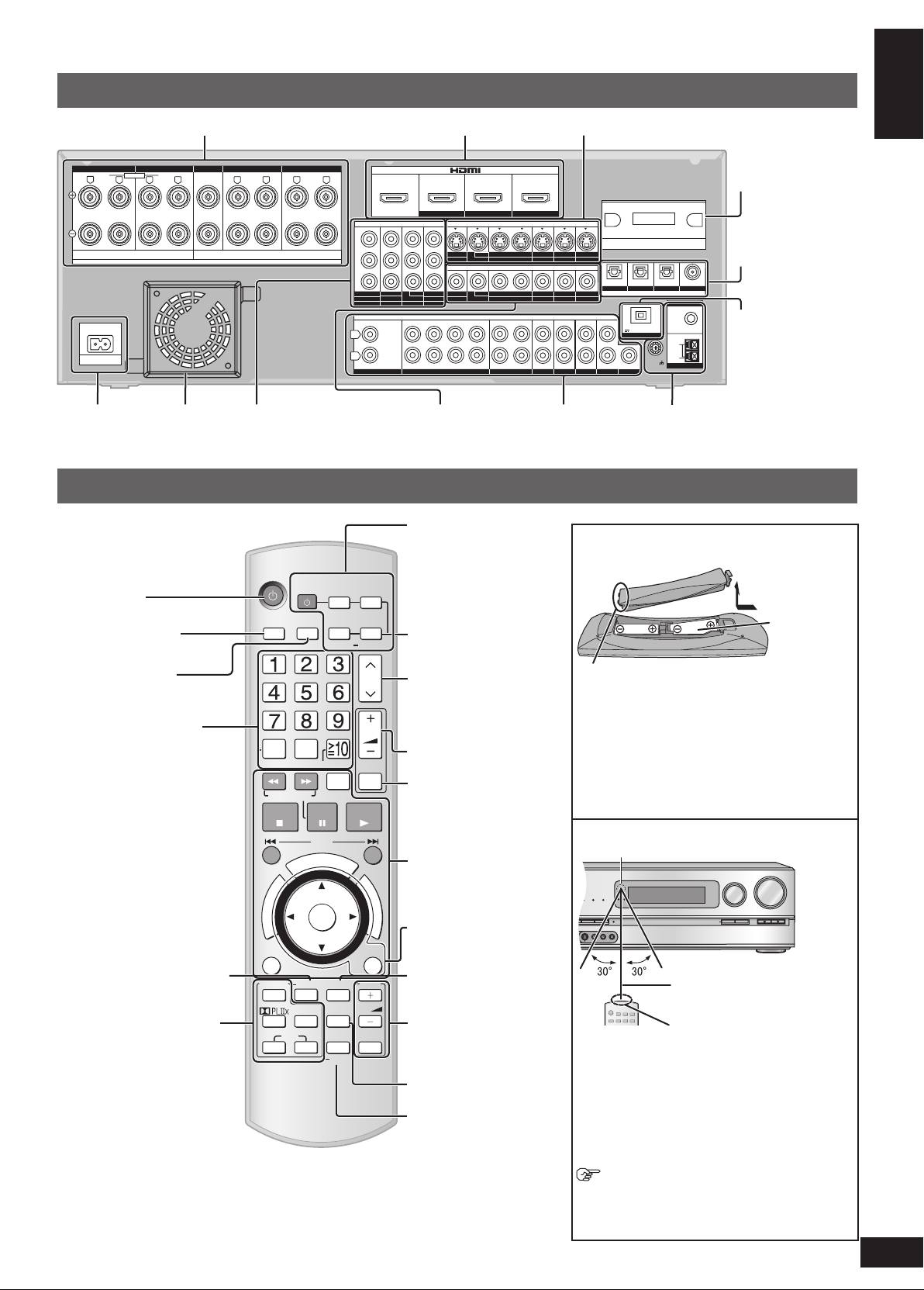
Rear Panel
WIRELESS READY
SURROUND M.ROOM
INPUT SELECTOR
VOLUME
+
_
DTS-HD
MULTI CH
LPCM
BI-AMP
AUX
TUNE
RETURN
AUTO SPEAKER SETUP
-
SETUP
OK
SPEAKERS A
SPEAKERS B
S VIDEO
VIDEO
L
- AUDIO - R
O
O
U
C
H
P
L
A
Y
O
N
E
T
O
U
C
H
P
L
A
Y
D
I
R
E
C
T
N
A
V
I
G
A
T
O
R
T
O
P
M
E
N
U
F
U
N
C
T
I
O
N
S
0
AV
SYSTEM
TV
RECORDER
DVD
BD/DVD
PLAYERCABLE
ANALOG 8CH
SAT
OPTION
PORT
FM/AM
CH
VOL
SKIP
SEARCH/SLOW
STOP
PAUSE
PLAY
DRIVE
SELECT
MUTING
OK
RETURN
OFF
SURROUND
SOUND
TV
VOL
NEO : 6
SFC
MUSIC MOVIE
MENU
DISPLAY
DISC
DIRECT
TUNING
TEST
AUTO
SETUP
INPUT
SELECTOR
ENTER
SUB MENU
S
TV/VIDEO
BI-WIRE
LF HF
L
R
FRONT A
FRONT B
CENTER
SURROUND SURROUND BACK
OUT
IN IN
CD
BD/DVD PLAYER / ANALOG 8CH IN DVD RECORDER
VCR
CABLE/SAT
GAME
TV
AUDIO
SURROUND BACK
SURROUND
FRONT
SUBWOOFER
OUT
IN IN
IN
(DVD RECORDER)
(BD/DVD PLAYER)
(CABLE/SAT)
HDMI 1
HDMI 2 HDMI 3
FRONT A FRONT B CENTER
SURROUND
SURROUND BACK
S VIDEO
COMPONENT VIDEO
L
R
IN IN IN
IN
A
C IN~
OUT
IN
IN
OUT
OUT
IN IN IN
IN
TV MONITOR
TV MONITOR
DVD RECORDER
VCR
CABLE/SAT
GAME
DVD PLAYER
BD/(BD/
DVD PLAYER)
(DVD RECORDER)
(CABLE/SAT)
1 2 3
DIGITAL IN
(DVD RECORDER)
(BD/DVD PLAYER)
(TV)
(CD)
OPTICAL 1
OPTICAL 2 OPTICAL 3 COAXIAL
SUBWOOFER
Y
P
B
P
R
IN
OUT OUT
IN IN IN IN
TV MONITOR
DVD RECORDER
VCR
CABLE/SAT
GAME
DVD PLAYER
BD/
OUT
CENTER
IN
IN
FM ANT
AM ANT
OPTION V.1
LOOP
EXT
DC OUT/SORTIE C.C.
5V 500mA MAX
75
Ω
R
L
RR
L L
LOOP ANT
GND
VIDEO
SPEAKERS
HAUT-PARLEURS
Class2 wiring
A OR B/BI-WIRE : 4-8 Ω / EAC H SPEA KER (C HAQUE)
A AND B : 6-8 Ω / EAC H SPEA KER (C HAQUE)
6-8 Ω / EACH SPEAKER (CHAQUE)
Speaker terminals (➔ pa
C inlet
A
(➔ pa
ge 12)
Exhaust hole
(Cooling fan)
Remote control
Power button
ges 10, 11 and 22)
Component Video
terminals (➔ page 19)
HDMI terminals (➔ pa
Video terminals
(➔ pages 17 and
21)
For s
source on and off/
Source switching/
Switching remote control
modes (➔ pa
ges 12, 13, 16 and 32)
Audio terminals
(➔ pa
21)
witching an input
ges 42 to 46)
S video terminals (➔ pa
Antenna terminal
ges 11, 16 to
(➔ page 23)
Batteries
Press on the tab to open.
ges 18 and 21)
Digital transmitter
terminal
ge 23)
(➔ pa
Digital input terminals
(➔ pages 12, 13, 16
to 20 and 32)
Option port terminal
ge 47)
(➔ pa
Before use
Supplied accessories / Control guide
For selecting input
sour
and 41)
For switching FM or
AM (➔ pa
For inputting channels
TV, cable box and satellite
receiver (➔ pa
DVD recorder
(➔ page 43)
Radio (➔ pa
For selecting a trac
chapter
DVD recorder (➔ pa
Blu-ray Disc/DVD player
(➔ page 44)
For inputting frequencies
(➔ page 49)
or confirming speaker
F
output (➔ pa
speaker setup (➔ pages
24 and 25)/For adjusting
speaker le
For listening to surr
sounds (➔ pa
ces (➔ pages 26
ges 48 and 49)
ge 42)
ge 48)
vel (➔
ge 14)/For auto
page 31)
ges 28 to 30)
k or
ge 43)
ound
ying 8 channels
For pla
sources (➔ pa
For selecting a channel
TV, cable box and satellite
receiver (➔ pa
DVD recorder (➔ page 43
Radio (➔ pa
For adjusting v
ges 14, 15, 26 and
(➔ pa
41)
For silencing speaker
temporarily (➔ pa
For operating other
equipment
ges 33 and 42 to 44)
(➔ pa
For operating SOUND
MENU (➔ pages 34 and
35)/SETUP (➔ page 36)
For selecting SOUND
MENU (➔ pages 34 and
35)
For operating a
(➔ pa
ge 42)
For c
(➔ pa
For playing an iPod (➔
ge 47)/For entering
pa
SETUP menu items
(➔ pa
hanging the display
ges 31 and 48)
ge 36)
ge 27)
ge 42)
ge 48)
olumes
ge 31)
TV
Place this side in before the other side
when you close.
)
• Insert so the poles (( and )) match those in the
remote control.
• Do not use rechargeable type batteries.
• Do not heat or expose to flame.
• Do not leave the batteries in an automobile
s
exposed to direct sunlight for a long period of
time with doors and windows closed.
Use
Remote control signal sensor
About 7 meters (23 feet) or less
when you sit directly in front of
the signal sensor (Exact distance
depends on angles).
Transmission window
Caution
• Do not place an object between the signal
sensor and the remote control.
• Do not place the signal sensor under direct
sunlight or the strong light of an inverter
fluorescent lamp.
• Keep the transmission window and the unit’s
sensor free from dust.
The remote controlling range may decrease
When you set the unit in a cabinet
depending on the thickness or colors of glass
cabinet doors.
(R6/LR6, AA)
7
RQT9223
8
RQT9223
Quick guide
〜♪
This section guides you through the easiest and simplest way to setup the Home Theater.
Refer to the steps indicated below. The steps 1 to 4 indicate the method one by one from when you purchase
the unit until you can enjoy the Home Theater.
• Turn off all equipment before making any connections.
• Peripheral equipment sold separately unless otherwise indicated.
• To connect equipment, refer to the appropriate operating instructions.
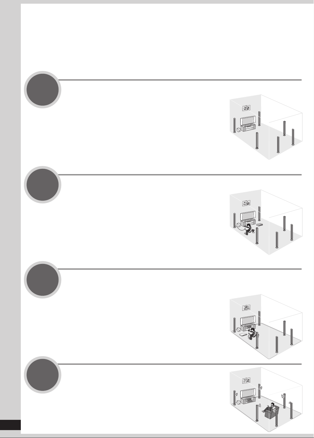
Step
1
Step
2
Placing speakers
You can enjoy the best sound quality by
setting speakers properly.
(➔ pa
Connecting speakers
You can install and connect speakers in
7.1ch setting.
ge 9)
(➔ pa
ges 10 and 11)
Step
3
Step
4
Connecting a TV and a Blu-ray Disc/DVD player
(➔ pa
You can easily enjoy high-quality pictures
and sounds.
Watching TV or DVD
You can enjoy TV and DVD with surround
sound.
ges 12 and 13)
(➔ pa
ges 14 and 15)
Quick guide
9
RQT9223
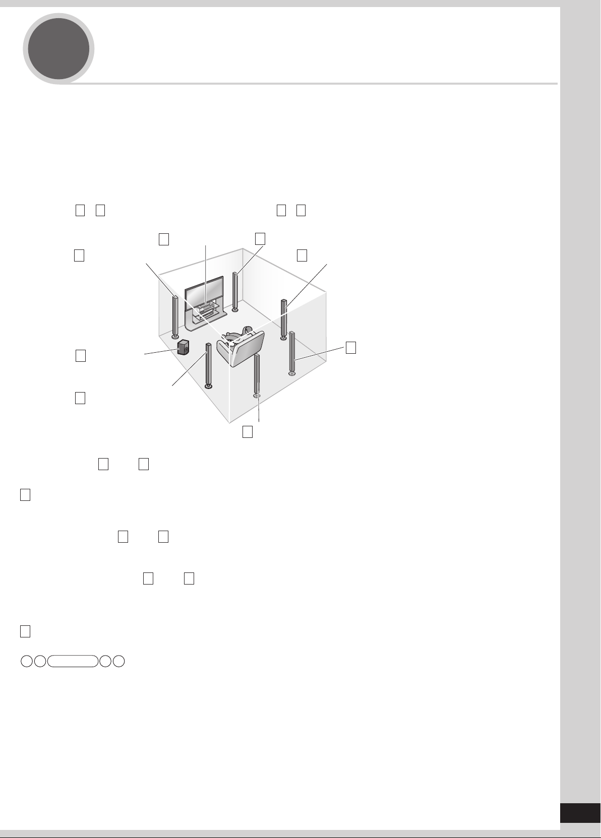
Step
1
5.1, 6.1, 7.1 etc. channel playback is possible on this unit. This page introduces speaker settings for 7.1 channel
playback.
The ideal placement is to set each speaker (excluding the subwoofer) the same distance away from the listening-viewing
position.
Measure the actual distance from each of the connected speakers to the listening-viewing position and perform steps
instructed in “Setting distances” (➔ page 37) or perform steps instructed in “Auto speaker setup using the setup
microphone” (➔ pages 24 and 25) when you cannot install speakers the same distance away.
Example: Front speakers (2), center speaker (1), surround speakers (2), surround back speakers (2) and
Placing speakers
subwoofer (1)
A
– H in the illustration below correspond to A – H in “Connecting speakers” (➔ pages 10 and 11).
Front speaker (right)
A
Surround speaker (right)
D
F
Surround back speaker
(right)
Front speaker (left)
B
Active
H
subwoofer
Center speaker
C
Placing speakers
Surround speaker (left)
E
Surround back speaker (left)
G
Front speakers (A
Place on the left and right of the TV at seated ear height so that there is good coherency between the picture and sound.
C Center speaker
Place underneath or above the center of the TV.
When you do not install the center speaker, sound assigned to it is distributed to front speakers and output from them.
Surround speakers (D right, E left)
Place on the side of or slightly behind the listening-viewing position.
When you do not install surround speakers, sound assigned to them is distributed to front speakers and output from them.
Surround back speakers ( F right, G left)
Place behind the listening-viewing position, about 1 meter (3 feet) higher than ear level.
When you do not install any surround back speaker, sound assigned to them is distributed to surround speakers or front speakers
and output from them.
H Active Subwoofer
The subwoofer can be placed in any position as long as it is at a reasonable distance from the TV.
Note
• Aim front faces of all speakers at the listening-viewing position for setting.
right, B left)

10
RQT9223
Step
BI-WIRE
LF HF
L
FRONT A
FRONT B
CENTER
SURROUND SURROUND BACK
OUT
IN IN
CD
BD/DVD PLAYER / ANALOG 8CH IN DVD RECORDER
VCR
CABLE/SAT
GAME
TV
AUDIO
SURROUND BACK
SURROUND
FRONT
SUBWOOFER
OUT
IN IN
IN
(DVD RECORDER)
(BD/DVD PLAYER)
(CABLE/SAT)
HDMI 1
HDMI
2 HDMI 3
FRONT A CENTER
SURROUND
SURROUND BACK
S VIDEO
COMPONENT VIDEO
L
R
IN IN IN
IN
OUT
IN IN
OUT
OUT
IN IN IN
IN
TV MONITOR
TV MONITOR
DVD RECORDER
VCR
CABLE/SAT
GAME
DVD PLAYER
BD/(BD/
DVD PLAYER)
(DVD RECORDER)
(CABLE/SAT)
1 2
3
DIGITAL IN
(DVD RECORDER) (BD/DVD PLAYER)
OPTICAL 1
OPTICAL 2 OPTICAL 3 COAXIAL
SUBWOOFER
Y
P
B
P
R
IN
OUT OUT
IN IN IN IN
TV MONITOR
DVD RECORDER
VCR
CABLE/SAT
GAME
DVD PLAYER
BD/
OUT
CENTER
IN
IN
R
L
R
R R
L L
LOOP ANT
GND
VIDEO
AC IN~
OPTION V.1
DC OUT/SORTIE C.C.
5V 500mA MAX
SPEAKERS
HAUT-PARLEURS
Class2 wiring
A OR B/BI-WIRE : 4-8 Ω / EAC H SPEA KER ( CHAQUE)
A AND B : 6-8 Ω / EAC H SPEA KER ( CHAQUE)
6-8 Ω / EACH SPEAKER (CHAQUE)
FRONT B
CENTER
CENTER
LF
L
R
FRONT A
FRONT A
BI-WIRE
( )
( )
2
1
Remove the vinyl
covering the tips of
speaker cables by
twisting it off.
Front speaker (right)
A
Connecting speakers
How to connect speaker cables
2
Speaker terminals
Front speaker (left)
B
• Connect speaker cables properly to
terminals after making sure left and right,
and ( and ).
cause the unit to develop problems.
• Do not short-circuit speaker cables. The
action may damage circuits.
Note
Improper connections may
Center speaker
C
If using 4-mm plug
Turn speaker terminals
clockwise and tighten them
before inserting plugs into their
holes.
Rear panel
Speaker impedance
Front A: 4 to 8
Center:
Surr
Surr
• Do not forget to take steps instructed in “Auto speaker setup using the setup microphone” (➔ pages 24 and 25) after connecting a
6 to 8
ound: 6 to 8
ound back: 6 to 8
Note
Ω
Ω
Ω
Ω
new speaker.
• When connecting speakers with the impedance of 4 Ω, mak
e sure to set “4 OHMS ” in “Setting the speaker impedance” on page 38.
Quick guide
11
RQT9223
OUT
IN IN
BD/DVD PLAYER / ANALOG 8CH IN DVD RECORDER
VCR
CABLE/SAT
GAME
TV
AUDIO
SURROUND BACK
SURROUND
FRONT
IN IN
IN
(DVD RECORDER)
(BD/DVD PLAYER)
(CABLE/SAT)
HDMI 1
HDMI
2 HDMI 3
S VIDEO
IN IN IN
OUT
OUT
IN IN IN
IN
TV MONITOR
DVD RECORDER
VCR
CABLE/SAT
GAME
DVD PLAYER
BD/(BD/
(CABLE/SAT)
3
DIGITAL IN
(DVD RECORDER) (BD/DVD PLAYER)
(TV)
(CD)
OPTICAL 1
OPTICAL 2 OPTICAL 3 COAXIAL
SUBWOOFER
IN
OUT OUT
IN IN IN IN
TV MONITOR
DVD RECORDER
VCR
CABLE/SAT
GAME
DVD PLAYER
BD/
OUT
IN
IN
FM ANT
AM ANT
LOOP
EXT
75
Ω
LOOP ANT
GND
VIDEO
OPTION V.1
DC OUT/SORTIE C.C.
5V 500mA MAX
SUBWOOFER
OUT
SURROUND BACK
SURROUND BACK
R
L
SURROUND
R
L
SURROUND
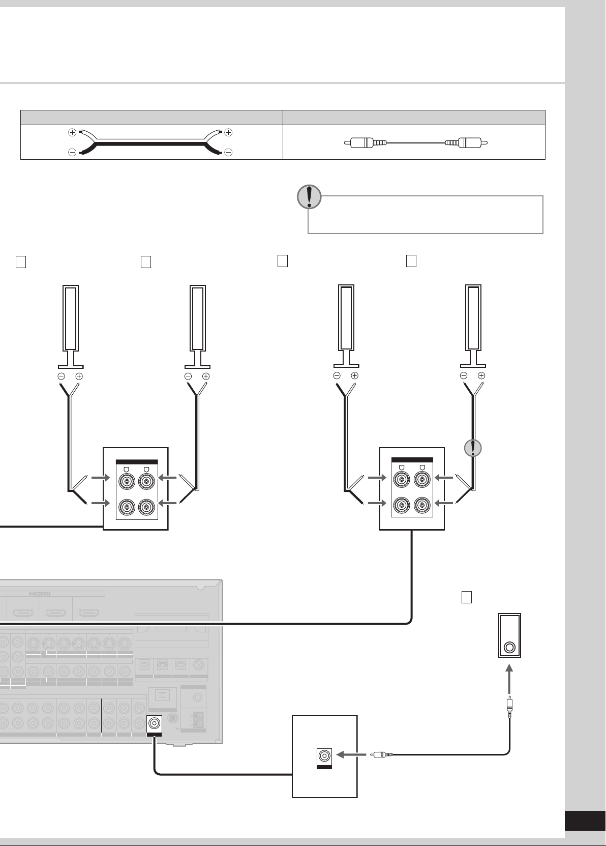
Connection cable
Speaker cable (not included) Monaural connection cable (not included)
Use the terminal for the left surround back
speaker when you place the speakers for 6.1
channel playback.
D
Surround speaker
(right)
E
Surround speaker
(left)
F
Surround back speaker
(right)
G
Surround back speaker
(left)
Connecting speakers
Active subwoofer
H
12
RQT9223
Step
BI-WIRE
LF HF
L
R
FRONT A
FRONT B
CENTER
SURROUND SURROUND BACK
OUT
IN IN
CD
BD/DVD PLAYER / ANALOG 8CH IN DVD RECORDER
VCR
CABLE/SAT
GAME
AUDIO
SURROUND BACK
SURROUND
FRONT
SUBWOOFER
OUT
IN IN
IN
(DVD RECORDER)
(BD/DVD PLAYER)
(CABLE/SAT)
HDMI 1
HDMI 2 HDMI 3
FRONT A FRONT B CENTER
SURROUND
SURROUND BACK
S VIDEO
COMPONENT VIDEO
L
R
IN IN IN
IN
A
C IN~
OUT
IN
IN
OUT
OUT
IN IN IN
IN
TV MONITOR
TV MONITOR
DVD RECORDER
VCR
CABLE/SAT
GAME
DVD PLAYER
BD/(BD/
DVD PLAYER)
(DVD RECORDER)
(CABLE/SAT)
1 2
3
(DVD RECORDER) (BD/DVD PLAYER)
(CD)
OPTICAL 1
OPTICAL 2 COAXIAL
SUBWOOFER
Y
P
B
P
R
IN
OUT OUT
IN IN IN IN
TV MONITOR
DVD RECORDER
VCR
CABLE/SAT
GAME
DVD PLAYER
BD/
OUT
CENTER
IN
IN
FM ANT
AM ANT
OPTION V.1
LOOP
EXT
75
Ω
R
L
RR
L L
LOOP ANT
GND
VIDEO
TV
DC OUT/SORTIE C.C.
5V 500mA MAX
Class2 wiring
SPEAKERS
HAUT-PARLEURS
A OR B/BI-WIRE : 4-8 Ω / EAC H SPEA KER ( CHAQUE )
A AND B : 6-8 Ω / EAC H SPEA KER ( CHAQUE)
6-8 Ω / EACH SPEAKER (CHAQUE)
(TV)
OPTICAL 3
DIGITAL IN
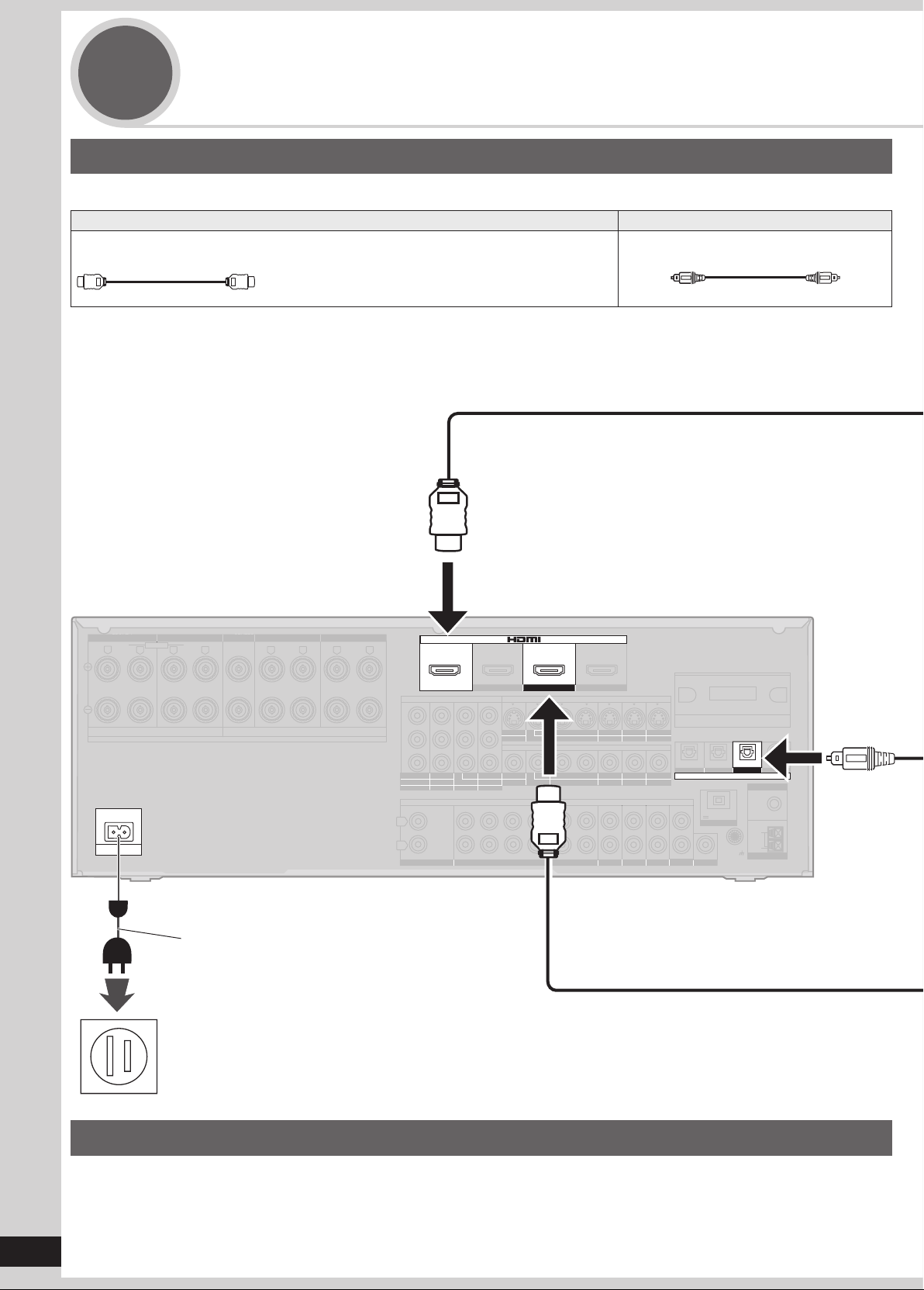
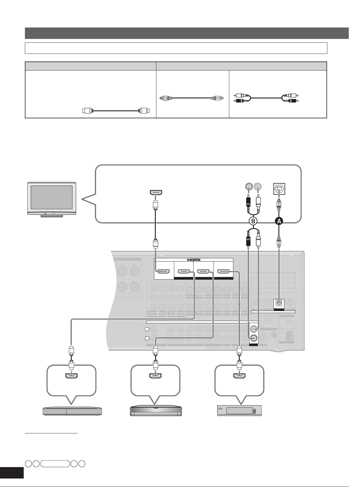
Connecting a TV and a Blu-ray Disc/
3
DVD player
Connecting equipment with HDMI terminal
Connection cable
Video and Audio cable Audio cable
HDMI Cable (not included) (It is recommended that you use Panasonic’s HDMI cable.)
Recommended part number:
RP-CDHG10 (1.0 m/3.3 ft.), RP-CDHG15 (1.5 m/4.9 ft.),
RP-CDHG20 (2.0 m/6.6 ft.), RP-CDHG30 (3.0 m/9.8 ft.),
RP-CDHG50 (5.0 m/16.4 ft.), etc.
Optical fiber cable (not included)
Rear panel
AC power supply cord (included)
Household AC outlet
(AC 120 V, 60 Hz)
Notes on AC power supply cord
• Connect AC power supply cord after all other cables and cords are connected.
• The included AC power supply cord is for use with this unit only. Do not use it with other equipment.
• Do not use an AC power supply cord from any other type of equipment with this unit.
• The unit’s settings remain effective after the AC power supply cord is removed from the household AC outlet.
Quick guide
13
RQT9223
WIRELESS READY
SURROUND M.ROOM
INPUT SELECTOR
VOLUME
+
_
MULTI CH
PROCESSING
T
rueHD
D+
DTS-HD
MULTI CH
LPCM
BI-AMP
SETUP MIC
AUX
TUNE
RETURN
AUTO SPEAKER SETUP
-
SETUP
OK
SURROUND
SPEAKERS A
SPEAKERS B
S VIDEO
VIDEO
L
- AUDIO - R
SURROUND
“
SURROUND
”
POWER
POWER
SURROUND
POWER
Note
• This unit incorporates HDMI™ (V.1.3 with Deep Color) technology that can reproduce greater color gradation (4096 steps)
when connected to a compatible TV. A lower color gradation (256 steps), without deep color, will be reproduced if connected to a
TV which does not support deep color.
• Please use High Speed HDMI Cables that have the HDMI logo (as shown on the cover).
• When outputting 1080p signal, please use the HDMI cables 5.0 meters (16.4 feet) or less.
• The audio signal transmitted through HDMI takes priority when you use both HDMI and digital terminals for connection
(
pages 16 to 20).
➔
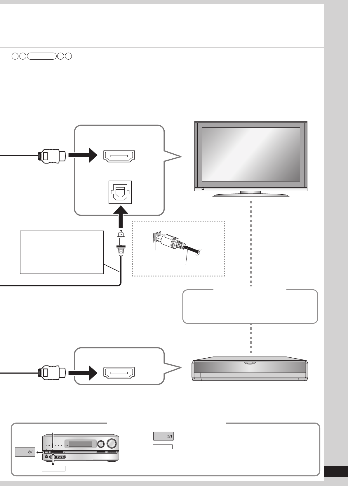
TV
HDMI input
Digital audio out (optical)
Connecting the optical fiber cable
You need an optical fiber cable for
enjoying TV with a digital sound
output.
To enjoy TV with analog surround
sound mak
instr
e connection
ucted on page 16.
as
Video/A
HDMI
udio out
Note the
shape and fit it
correctl
y into
the terminal.
Do not bend!
Standby through function
You can hear DVD sounds, etc. from TV speakers
when you turn off the unit connected as shown on
this page. This convenient function enables you to
enjoy DVD etc. without using the unit late at night.
Blu-ray Disc/DVD player
Connecting a TV and a Blu-ray Disc/DVD player
When connection is complete
1. Press to turn the unit on.
2. Press
• The “SURROUND” indicator lights on after the setting.
• You can enjoy 2-channel sources with surround playback.
to set surround playback.
14
RQT9223
Step
ENTER
SUB MENU
S
TV/VIDEO
WIRELESS READY
SURROUND M.ROOM
INPUT SELECTOR
VOLUME
+
_
MULTI CH
PROCESSING
TrueHD
D+
DTS-HD
MULTI CH
LPCM
BI-AMP
SETUP MIC
AUX
TUNE
RETURN
AUTO SPEAKER SETUP
-
SETUP
OK
SURROUND
SPEAKERS A
SPEAKERS B
S VIDEO
VIDEO
L - AUDIO - R
“ ”
SURROUND
“
SURROUND
”
SPEAKERS A
POWER
TEST
AUTO
TEST
AUTO
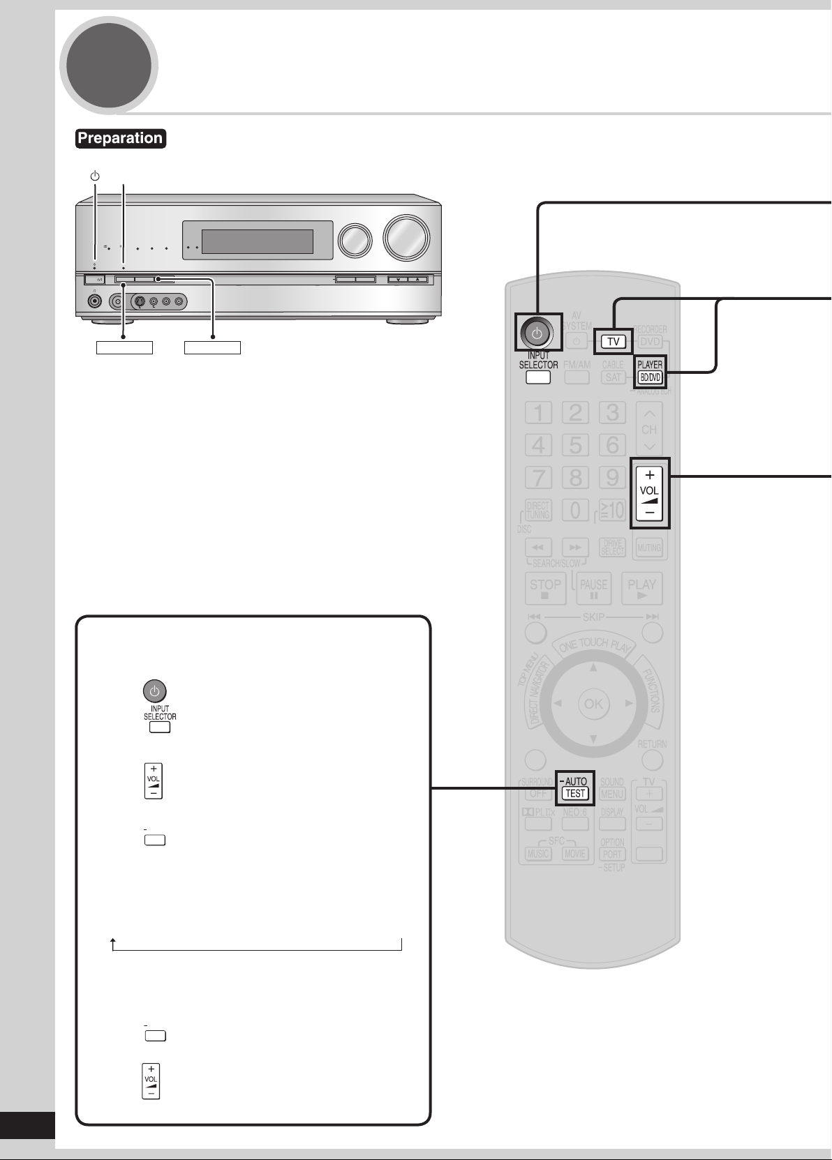
4
Watching TV or DVD
Turn the TV on and switch the TV’s input mode (to “HDMI” and others)
You can confirm audio output using the test signal.
1. Press to turn the unit on.
2. Press to select an input source other than
“TV ” or “BD/DVD P. ”.
3.
Press
–30dB and –35dB.
4. Press
connected speakers.
When you feel the volume of each speaker is not
balanced with the volume of the front speakers, see
page 31 to adjust the volume balance of speakers.
5. Press to stop the test signal.
6. Lower the volume to the normal listening level
using .
Testing speaker output
to adjust the v
to test audio output fr
• Speakers are displayed in the following order.
(The test signal is output only when the
connected speaker is displayed.)
→
L
C → R → RS → SBR → SBL → LS → SUBW
olume range between
om all
Quick guide
15
RQT9223
POWER
INPUT SELECTOR
VOLUME
+
_
WIRELESS READY
SURROUND M.ROOM
INPUT SELECTOR
VOLUME
+
_
MULTI CH
PROCESSING
TrueHD
D
+
DTS-HD
MULTI CH
LPCM
B
I-AMP
SETUP MIC
AUX
TUNE
RETURN
AUTO SPEAKER SETUP
-
SETUP
OK
SURROUND
SPEAKERS A
SPEAKERS B
S VIDEO
VIDEO
L - AUDIO - R
POWER
1
A
A
To turn the unit on
Press
To select “TV ” or “BD/DVD P. ”.
• The standby indicator “^”
• Confirm if “
If “ ” is not displayed, press [SPEAKERS A].
• Check the “SURROUND” indicator is lighting up. If not, press
[SURROUND] on the unit to set surround playback
(➔ pages 13 and 29).
” appears on the display on the unit.
goes off when you turn the unit on.
2
3
4
Press or
Watch TV or DVD
To adjust the volume
Press
To finish watching
Be sure to reduce the volume and press [^] to tur
Operations on the unit
• You can enjoy a variety of surround effects (➔ pages 28 to 30).
Volume range:
– – dB (minimum), – 79dB to 0dB (maximum)
n the unit to standby.
To turn the unit on
1
Press
Watching TV or DVD
To select “TV ” or “BD/DVD P. ”
2
Turn
Watch TV or DVD
3
To adjust the volume
4
Turn
Connections
SURROUND SURROUND BACK
OUT
IN IN
CD
BD/DVD PLAYER / ANALOG 8CH IN DVD RECORDER
VCR
CABLE/SAT
GAME
AUDIO
SURROUND BACK
SURROUND
FRONT
SUBWOOFER
OUT
IN IN
IN
(DVD RECORDER)
(BD/DVD PLAYER)
(CABLE/SAT)
HDMI 1
HDMI
2 HDMI 3
SURROUND
SURROUND BACK
S VIDEO
COMPONENT VIDEO
L
R
IN IN IN
IN
OUT
IN
IN
OUT
OUT
IN IN IN
IN
TV MONITOR
TV MONITOR
DVD RECORDER
VCR
CABLE/SAT
GAME
DVD PLAYER
BD/
(BD/
DVD PLAYER)
(DVD RECORDER)
(CABLE/SAT)
1 2
3
(DVD RECORDER) (BD/DVD PLAYER)
(CD)
OPTICAL 1
OPTICAL 2 COAXIAL
SUBWOOFER
Y
P
B
P
R
IN
OUT OUT
IN IN IN IN
TV MONITOR
DVD RECORDER
VCR
CABLE/SAT
GAME
DVD PLAYER
BD/
OUT
CENTER
IN
IN
FM ANT
AM ANT
LOOP
EXT
75
Ω
R
L
L
LOOP ANT
GND
VIDEO
Class2 wiring
CHAQUE)
OPTION V.1
DC OUT/SORTIE C.C.
5V 500mA MAX
(TV)
OPTICAL 3
DIGITAL IN
TV
Basic connections
Connecting equipment with HDMI terminal
Connection cable
Video and Audio cable Audio cable
HDMI cable
Recommended part number:
RP-CDHG10 (1.0 m/3.3 ft.), RP-CDHG15 (1.5 m/4.9 ft.),
RP-CDHG20 (2.0 m/6.6 ft.), RP-CDHG30 (3.0 m/9.8 ft.),
RP-CDHG50 (5.0 m/16.4 ft), etc.
HDMI cable notes
• It is recommended that you use Panasonic’s HDMI cable.
• This unit incorporates HDMI™ (V.1.3 with Deep Color) technology.
• Please use High Speed HDMI Cables that have the HDMI logo (as shown on the cover).
• When outputting 1080p signal, please use the HDMI cables 5.0 meters (16.4 feet) or less.
(not included)
Optical fiber cable
(not included)
Stereo connection cable
(not included)
White (L)
Red (R)
To enjoy TV with surround sound, make connection or sho
TV
HDMI input
Rear panel
wn below according to your equipment.
Audio out
(R) (L)
Digital audio
out (optical)
HDMI connection
The HDMI input terminal on the unit’s rear is made to specifications that presume connection of a DVD recorder / Blu-ray Disc/
DVD player etc. When other equipment is connected, sounds may not come out of the unit, or pictures shown on the equipment (TV)
connected to the HDMI output terminal may be disrupted.
In such cases, see pages 17, 18 and 19 and make connections other than HDMI.
• The audio signal transmitted through HDMI takes priority when you use both HDMI and digital terminals for connection (➔ pages 16 to 20).
16
• You can change the settings on HDMI 3 terminal according to the equipment to connect (➔ page 39).
RQT9223
HDMI
Video/Audio out
Note
DVD recorder
HDMI
Video/Audio out
HDMI
Video/Audio out
Blu-ray Disc/DVD player Cable box, satellite receiver, etc.
• Turn off all equipment before making any connections.
SURROUND SURROUND BACK
OUT
IN IN
CD
BD/DVD PLAYER / ANALOG 8CH IN DVD RECORDER
VCR
CABLE/SAT
GAME
TV
AUDIO
SURROUND BACK
SURROUND
FRONT
SUBWOOFER
OUT
IN IN
IN
(DVD RECORDER)
(BD/DVD PLAYER)
(CABLE/SAT)
HDMI 1
HDMI
2 HDMI 3
SURROUND
SURROUND BACK
S VIDEO
COMPONENT VIDEO
L
R
IN IN IN
IN
OUT
IN
IN
OUT
IN IN IN
IN
TV MONITOR
TV MONITOR
DVD RECORDER
VCR
CABLE/SAT
GAME
DVD PLAYER
BD/(BD/
DVD PLAYER)
(DVD RECORDER)
(CABLE/SAT)
1 2
3
(DVD RECORDER) (BD/DVD PLAYER)
(TV)
(CD)
OPTICAL 1
OPTICAL 2 OPTICAL 3 COAXIAL
SUBWOOFER
Y
P
B
P
R
IN
OUT OUT
IN IN IN IN
TV MONITOR
DVD RECORDER
VCR
CABLE/SAT
GAME
DVD PLAYER
BD/
OUT
CENTER
IN
IN
FM ANT
AM ANT
LOOP
EXT
75
Ω
RR
L L
LOOP ANT
GND
VIDEO
OUT
DIGITAL IN
OPTION V.1
DC OUT/SORTIE C.C.
5V 500mA MAX
Class2 wiring
CHAQUE)
1 2
• Peripheral equipment sold separately unless otherwise indicated.
• To connect equipment, refer to the appropriate operating instructions.
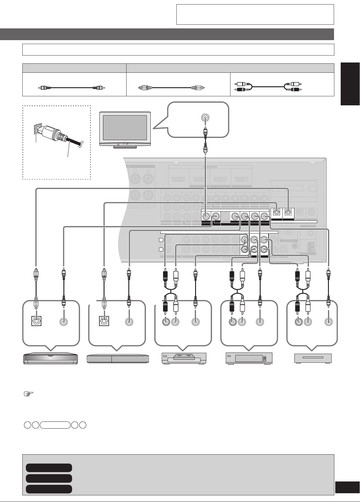
Connecting cables to video and audio terminals (Connecting equipment without HDMI terminal)
Connection cable
Video cable Audio cable
Video connection cable (not included)
Optical fiber cable (not included)
Stereo connection cable
(not included)
White (L)
Red (R)
Connecting the optical
fiber cable
Note the
shape and fit
it correctl
into the
y
Do not
bend!
terminal.
TV
VIDEO IN
To enjoy TV with surround
sound, make connection
or instructed on pa
ge 16
according to your equipment.
Rear panel
Preparations
Connections
Digital audio
out (optical)
DVD player
To connect a DVD recorder with built-in VCR
(When the DVD recorder has DVD/VHS terminals, make the following connections.)
Connect the D
Connect the DVD/VHS output terminal as
• When you make HDMI connections (➔ pages 12, 13 and 16), this connection is not necessar
• The input video signal can be sent out through an output terminal of the same type only.
• You can change the digital input terminal setting according to the equipment to connect (➔ page 39).
Playback is available with the basic connections (➔ pa
In addition To make high-picture-quality connections
In addition To enjoy analog sounds
In addition To connect other equipment, etc.
VIDEO
OUT
Digital audio
out (optical)
DVD recorderBlu-ray Disc/
VD output terminal as sho
Note
VIDEO
OUT
wn above.
sho
(➔ page 20)
(R) (L)
Audio out
VCR
wn above.
(➔ pages 18 and 19)
(➔ pages 20 to 23)
VIDEO
OUT
ge 26).
(R) (L)
Audio out
VIDEO
OUT
Cable box or
(R) (L)
Audio out
VIDEO
OUT
Game
satellite receiver
y.
17
RQT9223
Connections
SURROUND SURROUND BACK
OUT
IN IN
CD
BD/DVD PLAYER / ANALOG 8CH IN DVD RECORDER
VCR
CABLE/SAT
GAME
TV
AUDIO
SURROUND BACK
SURROUND
FRONT
SUBWOOFER
OUT
IN IN
IN
(DVD RECORDER)
(BD/DVD PLAYER)
(CABLE/SAT)
HDMI 1
HDMI
2 HDMI 3
SURROUND
SURROUND BACK
S VIDEO
COMPONENT VIDEO
L
R
IN IN IN
IN
OUT
IN
IN
OUT
OUT
IN IN IN
IN
TV MONITOR
TV MONITOR
DVD RECORDER
VCR
CABLE/SAT
GAME
DVD PLAYER
BD/(BD/
DVD PLAYER)
(DVD RECORDER)
(CABLE/SAT)
1 2
3
(DVD RECORDER) (BD/DVD PLAYER)
(TV)
(CD)
OPTICAL 1
OPTICAL 2 OPTICAL 3 COAXIAL
SUBWOOFER
Y
P
B
P
R
IN
OUT OUT
IN IN IN IN
TV MONITOR
DVD RECORDER
VCR
CABLE/SAT
GAME
DVD PLAYER
BD/
OUT
CENTER
IN
IN
FM ANT
AM ANT
LOOP
EXT
75
Ω
RR
L L
LOOP ANT
GND
VIDEO
DIGITAL IN
Class2 wiring
OPTION V.1
DC OUT/SORTIE C.C.
5V 500mA MAX
CHAQUE)
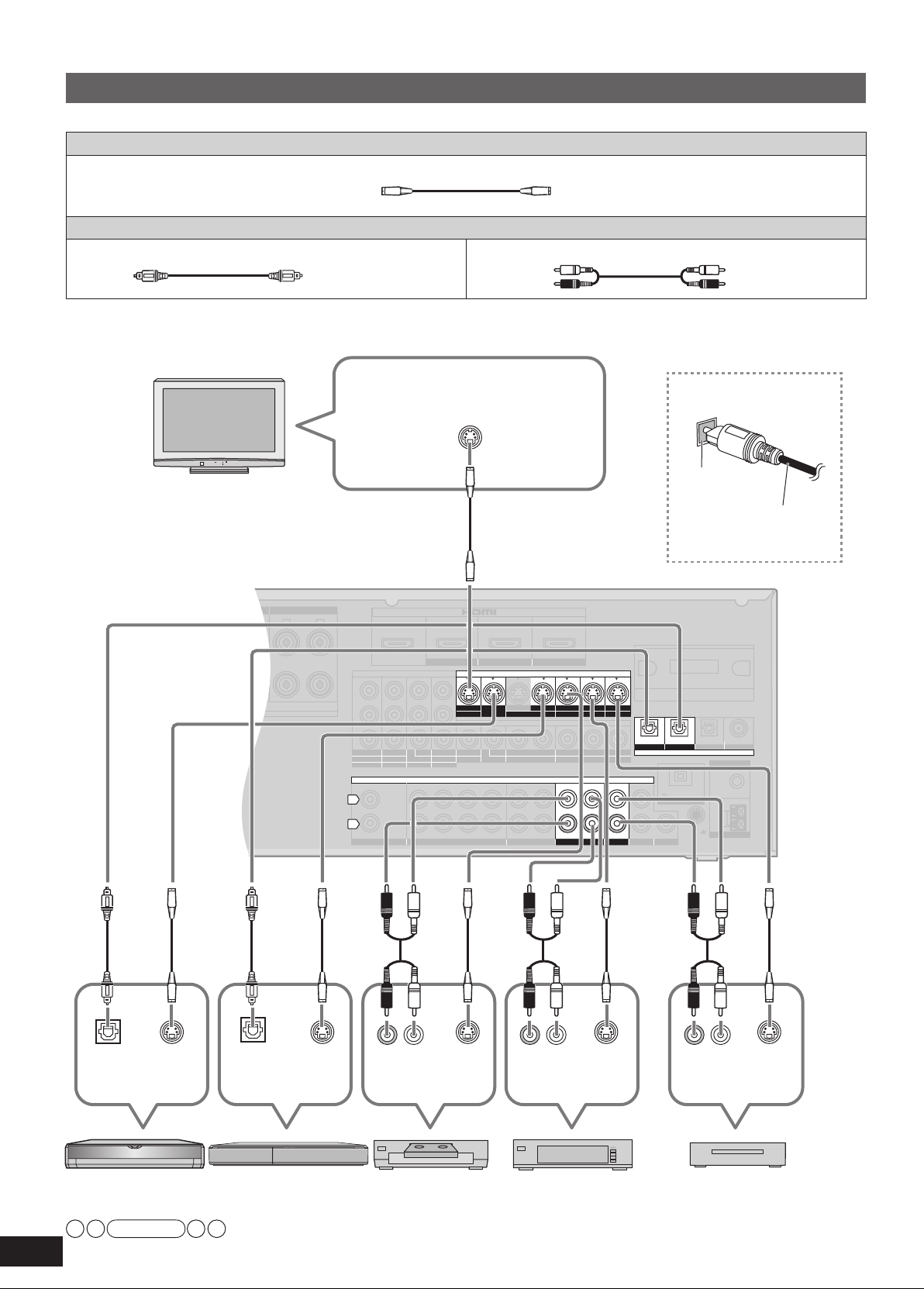
Connecting cables to S video and audio terminals
Connection cable
Video cable
S VIDEO connection cable (not included)
Audio cable
Optical fiber cable (not included) Stereo connection cable
To enjoy TV with surround sound, make connection or
TV
instructed on pa
S VIDEO IN
ge 16 according to your equipment.
(not included)
White (L)
Red (R)
Connecting the optical
fiber cable
Note the
shape and fit
it correctl
y
into the
terminal.
Do not
bend!
Rear panel
Digital audio
out (optical)
DVD player
• The input video signal can be sent out through an output terminal of the same type only.
18
• You can change the digital input terminal setting according to the equipment to connect (➔ page 39).
RQT9223
S VIDEO
Note
OUT
Digital audio
out (optical)
DVD recorderBlu-ray Disc/
S VIDEO
OUT
(R) (L)
Audio out
VCR
S VIDEO
OUT
(R) (L)
Audio out
Cable box or
satellite receiver
S VIDEO
OUT
(R) (L)
Audio out
Game
S VIDEO
OUT

• Turn off all equipment before making any connections.
SURROUND SURROUND BACK
OUT
IN IN
CD
BD/DVD PLAYER / ANALOG 8CH IN DVD RECORDER
VCR
CABLE/SAT
GAME
TV
AUDIO
SURROUND BACK
SURROUND
FRONT
SUBWOOFER
OUT
IN IN
IN
(DVD RECORDER)
(BD/DVD PLAYER)
(CABLE/SAT)
HDMI 1
HDMI
2 HDMI 3
SURROUND
SURROUND BACK
S VIDEO
COMPONENT VIDEO
L
R
IN IN IN
IN
OUT
IN
IN
OUT
OUT
IN IN IN
IN
TV MONITOR
TV MONITOR
DVD RECORDER
VCR
CABLE/SAT
GAME
DVD PLAYER
BD/(BD/
DVD PLAYER)
(DVD RECORDER)
(CABLE/SAT)
1 2
3
(DVD RECORDER) (BD/DVD PLAYER)
(TV)
(CD)
OPTICAL 1
OPTICAL 2 OPTICAL 3 COAXIAL
SUBWOOFER
Y
P
B
P
R
IN
OUT OUT
IN IN IN IN
TV MONITOR
DVD RECORDER
VCR
CABLE/SAT
GAME
DVD PLAYER
BD/
OUT
CENTER
IN
IN
FM ANT
AM ANT
LOOP
EXT
75
Ω
RR
L L
LOOP ANT
GND
VIDEO
DIGITAL IN
Class2 wiring
OPTION V.1
DC OUT/SORTIE C.C.
5V 500mA MAX
CHAQUE)
Y PBP
R
Y PB PR Y PB PRY PB PR
• Peripheral equipment sold separately unless otherwise indicated.
• To connect equipment, refer to the appropriate operating instructions.
Connecting cables to component and audio terminals
The component video terminals can produce more accurate colors than the S video terminals (➔ page 18).
Connection cable
Video cable Audio cable
Video connection cable (not included)
Optical fiber cable (not included)
Stereo connection cable
(not included)
White (L)
Red (R)
TV
To enjoy TV with surround sound, make connection or
instructed on pa
COMPONENT
VIDEO IN
ge 16 according to your equipment.
Connecting the optical
fiber cable
Note the
shape and fit
it correctl
into the
terminal.
Rear panel
Preparations
Connections
y
Do not
bend!
Digital audio
out (optical)
Component video terminals
The component video terminals (color-difference video terminals) output red (PR), blue (PB), and luminance (Y) signals
separately. The terminals reproduce colors with greater accuracy for this reason.
• The input video signal can be sent out through an output terminal of the same type only.
• You can change the settings for the digital input terminal and Component Video 3 terminal according to the equipment to connect (➔ page 39).
(R) (L)
udio out
A
Cable box or
satellite receiver
COMPONENT
VIDEO OUT
Digital audio
out (optical)
DVD player
COMPONENT
VIDEO OUT
COMPONENT
VIDEO OUT
DVD recorder Blu-ray Disc/
Note
19
RQT9223

Connections
ACK
OUT
IN IN
CD
BD/DVD PLAYER / ANALOG 8CH IN DVD RECORDER
VCR
CABLE/SAT
GAME
TV
AUDIO
SURROUND BACK
SURROUND
FRONT
SUBWOOFER
OUT
IN IN
IN
(DVD RECORDER)
(BD/DVD PLAYER)
(CABLE/SAT)
HDMI 1
HDMI 2 HDMI 3
S VIDEO
COMPONENT VIDEO
IN IN IN
IN
OUT
IN
IN
OUT
OUT
IN IN IN
IN
TV MONITOR
TV MONITOR
DVD RECORDER
VCR
CABLE/SAT
GAME
DVD PLAYER
BD/(BD/
DVD PLAYER)
(DVD RECORDER)
(CABLE/SAT)
1 2
3
(DVD RECORDER) (BD/DVD PLAYER)
(TV)
OPTICAL 1
OPTICAL 2 OPTICAL 3
SUBWOOFER
Y
P
B
P
R
IN
OUT O
UT
IN IN IN IN
TV MONITOR
DVD RECORDER
VCR
CABLE/SAT
GAME
DVD PLAYER
BD/
OUT
CENTER
IN
IN
FM ANT
AM ANT
LOOP
EXT
75
Ω
L
LOOP ANT
GND
VIDEO
L
R
DIGITAL IN
(CD)
COAXIAL
OPTION V.1
DC OUT/SORTIE C.C.
5V 500mA MAX
CK
OUT
IN IN
CD
BD/DVD PLAYER / ANALOG 8CH IN DVD RECORDER
VCR
CABLE/SAT
GAME
TV
AUDIO
SURROUND BACK
SURROUND
FRONT
SUBWOOFER
OUT
IN IN
IN
(DVD RECORDER)
(BD/DVD PLAYER)
(CABLE/SAT)
HDMI 1
HDMI 2 HDMI 3
S VIDEO
COMPONENT VIDEO
L
R
IN IN IN
IN
OUT IN
IN
OUT
OUT
IN IN IN
IN
TV MONITOR
TV MONITOR
DVD RECORDER
VCR
CABLE/SAT
GAME
DVD PLAYER
BD/(BD/
DVD PLAYER)
(DVD RECORDER)
(CABLE/SAT)
1 2
3
DIGITAL IN
(DVD RECORDER) (BD/DVD PLAYER)
(TV)
(CD)
OPTICAL 1
OPTICAL 2 OPTICAL 3 COAXIAL
SUBWOOFER
Y
P
B
P
R
IN
OUT O
UT
IN IN IN IN
TV MONITOR
DVD RECORDER
VCR
CABLE/SAT
GAME
DVD PLAYER
BD/
OUT
CENTER
IN
IN
FM ANT
AM ANT
LOOP
EXT
75
Ω
LOOP ANT
GND
VIDEO
OPTION V.1
DC OUT/SORTIE C.C.
5V 500mA MAX
CK
OUT
IN IN
CD
BD/DVD PLAYER / ANALOG 8CH IN DVD RECORDER
VCR
CABLE/SAT
GAME
TV
AUDIO
SURROUND BACK
SURROUND
FRONT
SUBWOOFER
OUT
IN IN
IN
(DVD RECORDER)
(BD/DVD PLAYER)
(CABLE/SAT)
HDMI 1
HDMI 2 HDMI 3
S VIDEO
COMPONENT VIDEO
L
R
IN IN IN
IN
OUT
IN
IN
OUT
OUT
IN IN IN
IN
TV MONITOR
TV MONITOR
DVD RECORDER
VCR
CABLE/SAT
GAME
DVD PLAYER
BD/(BD/
DVD PLAYER)
(DVD RECORDER)
(CABLE/SAT)
1 2
3
DIGITAL IN
(DVD RECORDER) (BD/DVD PLAYER)
(TV)
(CD)
OPTICAL 1
OPTICAL 2 OPTICAL 3 COAXIAL
SUBWOOFER
Y
P
B
P
R
IN
OUT O
UT
IN IN IN IN
TV MONITOR
DVD RECORDER
VCR
CABLE/SAT
GAME
DVD PLAYER
BD/
OUT
CENTER
IN
IN
FM ANT
AM ANT
LOOP
EXT
75
Ω
LOOP ANT
GND
VIDEO
OPTION V.1
DC OUT/SORTIE C.C.
5V 500mA MAX
Other connections
Connection cable
Video cable
Video connection cable (not included) S VIDEO connection cable (not included)
Audio cable
Coaxial cable
(not included)
Stereo connection cable
To enjoy analog sounds
Make analog connections according to your equipment and preference. See pages 17, 18 and 19 for video connections.
Rear panel
(not included)
White (L)
Red (R)
(L) AUDIO
(R) OUT
Blu-ray Disc/
DVD player
(L) AUDIO
(R) OUT
To enjoy high-quality analog sounds (Analog 8-channel connections)
See pages 17, 18 and 19 for video connections.
Rear panel
CENTER
SUBWOOFER
(L) SURROUND
(R) BACK
(L)
SURROUND
(R)
(L)
(R)
Note
• See page 27 for playback instructions.
• When you make HDMI connections (➔ pages 12, 13 and 16), this connection is not necessar
FR
y.
DVD recorder
Blu-ray Disc/DVD
player etc.
ONT
To connect the unit to a CD player
Make either digital audio (COAXIAL) output connections () or analog audio output connections () according to y
and preference.
Rear panel
RQT9223
20
• You can change the digital input terminal setting according to the equipment to connect (➔ page 39).
Note
DIGITAL
AUDIO OUT
(COAXIAL)
(L) AUDIO
(R) OUT
our equipment
CD player

• Turn off all equipment before making any connections.
OUT
IN IN
CD
BD/DVD PLAYER / ANALOG 8CH IN DVD RECORDER
VCR
CABLE/SAT
GAME
TV
AUDIO
SURROUND BACK
SURROUND
FRONT
SUBWOOFER
OUT
IN IN
IN
(DVD RECORDER)
(BD/DVD PLAYER)
(CABLE/SAT)
HDMI 1
HDMI 2 HDMI 3
COMPONENT VIDEO
L
R
IN IN IN
IN
OUT IN
IN
OUT
OUT
IN IN IN
IN
TV MONITOR
TV MONITOR
DVD RECORDER
VCR
CABLE/SAT
GAME
DVD PLAYER
BD/(BD/
DVD PLAYER)
(DVD RECORDER)
(CABLE/SAT)
1 2
3
DIGITAL IN
(DVD RECORDER) (BD/DVD PLAYER)
(TV)
(CD)
OPTICAL 1
OPTICAL 2 OPTICAL 3 COAXIAL
SUBWOOFER
Y
P
B
P
R
IN
OUT
OUT
IN IN IN IN
TV MONITOR
DVD RECORDER
VCR
CABLE/SAT
GAME
DVD PLAYER
BD/
OUT
CENTER
IN
IN
FM ANT
AM ANT
LOOP
EXT
75
Ω
L
LOOP ANT
GND
VIDEO
S VIDEO
OPTION V.1
DC OUT/SORTIE C.C.
5V 500mA MAX
WIRELESS READY
SURROUND M.ROOM
INPUT SELECTOR
VOLUME
+
_
MULTI CH
PROCESSING
TrueHD
D+
DTS-HD
MULTI CH
LPCM
BI-AMP
SETUP MIC
AUX
TUNE
RETURN
AUTO SPEAKER SETUP
-
SETUP
OK
SURROUND
SPEAKERS A
SPEAKERS B
S VIDEO
VIDEO
L - AUDIO - R
POWER
• Peripheral equipment sold separately unless otherwise indicated.
• To connect equipment, refer to the appropriate operating instructions.
To connect the unit for audio or picture recording
You can record audio or pictures to the equipment connected to DVD recorder output terminal (AUDIO, VIDEO, S VIDEO).
See page 41 for more details.
Rear panel
Preparations
Note
• Connect the recording unit and source unit using the same cable.
To connect the unit to a video camera etc.
These terminals are convenient for equipment you want to connect only temporarily.
Note
• Use a cable, or that belongs to the same type as the video cab
To remove
Ho
w to attach or remove the front terminal cover
• Attaching the cover is recommended to protect terminals when not in use.
To attach
The dent
S VIDEO
IN
DVD recorder, etc.
VIDEO IN
AUDIO
(L)
(R) IN
le you used for connecting the unit to your TV.
S VIDEO
OUT
VIDEO
OUT
AUDIO
(L)
(R) OUT
Connections
Video
camera
etc.
erminal cover
T
Place the dent on the left to insert. Press the dent. Hold the protr
usion to remove.
21
RQT9223

Connections
BI-WIRE
LF HF
L
R
FRONT A
FRONT B
CENTER
SURROUND SURROUND BACK
CD
FRONT A FRONT B CENTER
SURROUND
SURROUND BACK
L
R
IN
A
C IN~
OUT
TV MONITOR
(DVD RECORDER)
Y
P
B
P
R
R
L
RR
L L
6-8 Ω / EACH SPEAKER (CHAQUE)
A OR B/BI-WIRE : 4-8 Ω / EACH SPEA KER (C HAQUE)
A AND B : 6-8 Ω / EACH SPEA KER (C HAQUE)
Class2 wiring
SPEAKERS
HAUT-PARLEURS
BI-WIRE
LF HF
L
R
FRONT A
FRONT B
CENTER
SURROUND SURROUND BACK
CD
FRONT A FRONT B CENTER
SURROUND
SURROUND BACK
L
R
IN
A
C IN~
OUT
TV MONITOR
(DVD RECORDER)
Y
P
B
P
R
R
L
RR
L L
6-8 Ω / EACH SPEAKER (CHAQUE)
A OR B/BI-WIRE : 4-8 Ω / EACH SPEA KER (C HAQUE)
A AND B : 6-8 Ω / EACH SPEA KER (C HAQUE)
HF
LF
HF
LF
Class2 wiring
SPEAKERS
HAUT-PARLEURS
( )
( )
Connecting other speakers
To connect bi-wire speakers
Make sure to select “YES ” in “Making bi-wire setting” (➔ page 38) when you connect the unit to bi-wire speakers. The speakers
do not produce adequate sounds unless you make this setting.
If using 4-mm plug
Turn speaker terminals
clockwise and tighten
them before inserting
plugs into their holes.
Rear panel
Front speaker (R)
Rear view
Front speaker (L)
Rear view
Speaker cable
(not included)
Speaker impedance
BI-WIRE: 4 to 8 Ω
Note
• Make sure to connect speakers’ HF terminals with the unit’s FRONT B terminals, and speakers’ LF terminals with the unit’s
FRONT A terminals.
• Different amps for high frequency and low frequency signals produce BI-AMP stereo sounds that are clearer and higher in audio
quality when you play on 2 channels sources containing analog audio and 2-channel PCM signals (➔ page 51).
•
When connecting speakers with the impedance of 4 Ω, mak
e sure to set “4 OHMS ” in “Setting the speaker impedance” on page 38.
• See “Notes on “To connect bi-wire speakers”” on page 50 for more details.
To connect a second pair of front speakers (SPEAKERS B)
Make the following connections when you wish to install a second pair of speakers in another room and enjoy music there.
Rear panel
Front speaker (R)
Speaker impedance
Front A or B: 4 to 8
Fr
•
When connecting speakers with the impedance of 4 Ω, mak
• See “Notes on “SPEAKERS B”” on page 51 for more details.
22
RQT9223
ont A and B: 6 to 8 Ω
Note
Ω
Front speaker (L)
Speaker cable
(not included)
e sure to set “4 OHMS ” in “Setting the speaker impedance” on page 38.

• Turn off all equipment before making any connections.
OUT
IN IN
CD
BD/DVD PLAYER / ANALOG 8CH IN DVD RECORDER
VCR
CABLE/SAT
GAME
TV
AUDIO
SURROUND BACK
SURROUND
FRONT
SUBWOOFER
OUT
IN IN
IN
(DVD RECORDER)
(BD/DVD PLAYER)
(CABLE/SAT)
HDMI 1
HDMI
2 HDMI 3
ND BACK
S VIDEO
COMPONENT VIDEO
L
R
IN IN IN
IN
OUT
IN
IN
OUT
OUT
IN IN IN
IN
TV MONITOR
TV MONITOR
DVD RECORDER
VCR
CABLE/SAT
GAME
DVD PLAYER
BD/(BD/
DVD PLAYER)
(DVD RECORDER)
(CABLE/SAT)
1 2
3
DIGITAL IN
(DVD RECORDER) (BD/DVD PLAYER)
(TV)
(CD)
OPTICAL 1
OPTICAL 2 OPTICAL 3 COAXIAL
SUBWOOFER
Y
P
B
wiring
P
R
IN
OUT O
UT
IN IN IN IN
TV MONITOR
DVD RECORDER
VCR
CABLE/SAT
GAME
DVD PLAYER
BD/
OUT
CENTER
IN
IN
FM ANT
AM ANT
LOOP
EXT
75
Ω
L
LOOP ANT
GND
VIDEO
OPTION V.1
DC OUT/SORTIE C.C.
5V 500mA MAX
OUND BACK
OUT
IN IN
CD
BD/DVD PLAYER / ANALOG 8CH IN DVD RECORDER
VCR
CABLE/SAT
GAME
TV
AUDIO
SURROUND BACK
SURROUND
FRONT
SUBWOOFER
OUT
IN IN
IN
(DVD RECORDER)
(BD/DVD PLAYER)
(CABLE/SAT)
HDMI 1
HDMI
2 HDMI 3
ND BACK
S VIDEO
COMPONENT VIDEO
L
R
IN IN IN
IN
OUT
IN
IN
OUT
OUT
IN IN IN
IN
TV MONITOR
TV MONITOR
DVD RECORDER
VCR
CABLE/SAT
GAME
DVD PLAYER
BD/(BD/
DVD PLAYER)
(DVD RECORDER)
(CABLE/SAT)
1 2
3
DIGITAL IN
(DVD RECORDER) (BD/DVD PLAYER)
(TV)
(CD)
OPTICAL 1
OPTICAL 2 OPTICAL 3 COAXIAL
SUBWOOFER
Y
P
B
wiring
P
R
IN
OUT OUT
IN IN IN IN
TV MONITOR
DVD RECORDER
VCR
CABLE/SAT
GAME
DVD PLAYER
BD/
OUT
CENTER
IN
IN
FM ANT
AM ANT
LOOP
EXT
75
Ω
L
LOOP ANT
GND
VIDEO
OPTION V.1
DC OUT/SORTIE C.C.
5V 500mA MAX
1
2
1
3
2
FM ANT
75 Ω
• Peripheral equipment sold separately unless otherwise indicated.
• To connect equipment, refer to the appropriate operating instructions.
To enjoy wireless audio with SH-FX67
You can connect left and right surround speakers wirelessly by using Panasonic SH-FX67 (a set consisted of a digital transmitter
and a wireless system sold separately) with the unit (➔ page 27).
T
o use these options, insert the digital transmitter into the unit’s digital transmitter terminal and connect surround speakers to
SH-FX67’
s wireless system. See SH-FX67’s operating instructions for details.
Rear panel
How to insert the digital transmitter
Press the dents on both sides with force.
Dents
Use care because the
•
co
ver may pop out.
Remove the cover.
Insert firmly with the label side facing front.
Label
Preparations
Connections
Digital
ansmitter
tr
Note
• You can enjoy wireless speakers in another room (➔ page 27) (MUL
“MULTI ROOM ” in “Setting wireless speakers” (➔ page 39).
• When “MULTI ROOM ” is set, the surround speak
ers cannot be used wirelessly.
When the surround speakers are used wirelessly, you cannot set “MULTI ROOM ”.
•
By using 2 sets of SH-FX67, you can enjoy 7.1 channel playback, making the surround speakers and surround back speakers wireless.
In that case, make ID number setting (
Setting of the surround selector on SH-FX67 is necessary for 7.1 channel playback. See SH-FX67’s operating instructions for
•
page 27).
➔
more information.
TI ROOM). To use multi room function, make sure to select
Connecting antennas
When finished connecting antennas, tune the radio station once (➔ pages 48 and 49) and fix the antennas where reception is best.
Adhesive tape
AM loop antenna (included)
Rear panel
Keep the antenna cord away from DVD recorders,
Blu-ray Disc/DVD players, and other cords.
FM indoor antenna
(included)
Fix the other end of the
antenna where
reception is best.
FM outdoor antenna (not included)
• Disconnect the FM indoor antenna.
• The antenna should be installed by a competent
technician.
White
Red
k
Blac
FM outdoor
antenna
75 Ω coaxial cable
23
RQT9223

Auto speaker setup using the setup microphone
WIRELESS READY
SURROUND M.ROOM
INPUT SELECTOR
VOLUME
+
_
MULTI CH
PROCESSING
TrueHD
D
+
DTS-HD
MULTI CH
LPCM
B
I-AMP
SETUP MIC
AUX
TUNE
RETURN
AUTO SPEAKER SETUP
-
SETUP
OK
SURROUND
SPEAKERS A
SPEAKERS B
S VIDEO
VIDEO
L
- AUDIO - R
“ ”
“AUTO SPEAKER SETUP”
SPEAKERS A
POWER
POWER
TV/VIDEO
ENTER
SUB MENU
S
SETUP MIC
AUX
AUTO SPEAKER SETUP
SURROUND
SPEAKERS A
SPEAKERS B
S VIDEO
VIDEO
L - AUDIO - R
POWER
Using the supplied setup microphone, you can measure such items as distance from the seating area, polarity and size
and make adjustments for connected speakers.
Keep quiet during the auto speaker setup. Conversational voice, air-conditioning noise and small sounds made
by winds may cause an error or produce an incorrect setting. Speakers output loud test signals during the auto
speaker setup. Make sure to keep little children out of the room.
•
Mute the TV volume before starting the auto speaker setup.
•
When the subwoofer is connected, make sure it is turned on. (There are subwoofer models that turn off automatically.)
•
Set the subwoofer volume to the normal listening level.
•
Select “YES ”
in “Making bi-wire setting” (➔ page 38) when you connect the unit to bi-wire speakers.
To turn the unit on
Press [^].
1
The standby indicator “^”
goes off when you turn the unit on.
• You can also turn this unit on by pressing [POWER 8] on the unit.
24
RQT9223
Confirm “A” is displayed on the unit’s display.
2
• If “ A ” is not displayed, press [SPEAKERS A].
Connect the setup microphone (included).
3
Setup microphone
Place the setup microphone (included).
•
4
5
6
Place the setup microphone on a flat surface to
stabilize it.
Examples: A level bench sharing the height with
the seating area, a top section of a
sofa etc.
•
Set the microphone at seated ear height.
•
Use a tripod (for camera and other products) for
best results.
Tripod etc.
To start the setup
Press and hold [–AUTO, TEST] (on the remote control)
for 2 seconds.
•
The “AUTO SPEAKER SETUP” indicator flashes.
•
The unit cancels the auto speaker setup halfway through when you give a different
operational instruction before the setup finishes.
•
To cancel the setup halfway, press [–AUTO, TEST].
To finish the setup
•
When all auto settings are made, “COMPLETE ” appears and the “AUTO SPEAKER
SETUP” indicator lights on.
•
You can perform other operations after “COMPLETE ” is displayed. The unit keeps the
settings
Press [–AUTO, TEST] (on the remote control).
•
Unplug the setup microphone when the setup is finished.
even if you move straight on to another operation.

With the setup microphone, the unit automatically sets the following.
DISTANCE : The unit measures the distance between each speaker and the seating area and corrects the sound delay in the
seating area. The maximum speaker distance for correcting the delay is 15 meters (45 feet).
POLARITY :
SIZE / LEVEL / FREQUENCY : The unit measures acoustic characteristics of the room including speaker characteristics (size,
The unit checks the polarity of each speaker and, when the polarity is wrong, corrects it.
Select “CHECK NO ” in “Setting the unit against automatic polarity adjustment” (➔ page 38) before starting the auto
speak
er setup when you do not want the unit to adjust polarity automatically.
speaker connection status, output
level and lowpass filter settings) and adjusts them.
Note
•
The setup microphone is sensitive to heat. Keep it away from direct sunlight and avoid placing it on top of the unit.
•
These settings remain effective after the unit goes off.
•
The setup microphone jack is for use with the setup microphone only. Do not connect other microphones.
•
The volume may reach an extremely high level when you repeat the auto speaker setup.
When
•
the auto speaker setup is finished, check the volume before starting playback.
Setting the connection status and adjusting the level are the only available adjustment for the subwoofer through the auto speaker setup.
Such factors as speaker types, room conditions and speaker placement may cause the unit to set speaker size,
lowpass filter frequency and other items differently for the same type of speakers or produce settings that differ from
the actual characteristics of respective speakers.
When sound from speakers seems odd, check the following settings. When you find undesirable settings, correct them
manually.
See “Setting speakers and their sizes”, “Setting distances” and “Setting the lowpass filter” (➔ pages
37 and 38).•
Error messages
When one of the following error messages appears, press [–AUTO, TEST] to cancel and perform the auto speaker setup again.
Message Cause Countermeasure
CONNECT MIC
NO MIC
NOISY
MEASURING ERROR
CHECK CONNECTION
T
O SBL SPEAKER
NEED TO CONNECT
LS/RS SPEAKERS
CHECK CONNECTION
T
O LS SPEAKER
CHECK CONNECTION
T
O RS SPEAKER
CHECK CONNECTION
T
O L SPEAKER
CHECK CONNECTION
T
O R SPEAKER
LOW SIGNAL
The setup microphone is not connected.• Connect
•
The setup microphone comes off during the
speaker setup and correct measurement
auto
cannot be achieved.
Loud noise is preventing measurement.•
A speaker is too far.
•
An
error occurred from an unknown cause.
•
The right surround back speaker was
•
detected, but
was not detected.
Surround back speakers were detected, but
•
left and
detected.
The unit cannot detect the surround speaker
•
(left).
The unit cannot detect the surround speaker
•
(r
ight).
The unit cannot detect the front speaker (left).• Chec
The unit cannot detect the front speaker
•
(r
ight).
•
Test signals from the speakers are too weak
to allow accurate measurement with the
microphone.
the left surround back speaker
right surround speakers were not
Check to make sure the microphone is connected
•
properly.
P
erform the auto speaker setup again when the
•
room is quiet.
T
urn off an air-conditioner and other equipment
•
that are producing noise.
Chec
•
Perform the setup again.
•
•
Connect
terminal when you connect only one surround
back speaker.
Chec
•
connections.
•
Connect
connect surround back speakers.
Chec
Check connections.•
Check connections.•
• Change the microphone location (height,
direction etc.).
•
Check if there is any obstacle near a speaker
that is blocking the test signals.
• Set the subwoofer volume to the normal listening
level.
the setup microphone properly.•
k speaker locations.
to the left surround back speaker
k the left surround back speaker’s
surround speakers as well when you
k connections.•
k connections.•
Preparations
Auto speaker setup using the setup microphone
When the “AUTO SPEAKER SETUP” indicator is off after the auto speaker setup:
Auto speaker settings have been cancelled as a result of various setting changes.
25
RQT9223

Enjoying the Home Theater
ENTER
SUB MENU
S
TV/VIDEO
WIRELESS READY
SURROUND M.ROOM
INPUT SELECTOR
VOLUME
+
_
MULTI CH
PROCESSING
TrueHD
D
+
DTS-HD
MULTI CH
LPCM
B
I-AMP
SETUP MIC
AUX
TUNE
RETURN
A
UTO SPEAKER SETUP
-
SETUP
OK
SURROUND
SPEAKERS A
SPEAKERS B
S VIDEO
VIDEO
L
- AUDIO - R
“ ”
“SURROUND”
“MULTI CH PROCESSING”
SURROUND
SPEAKERS B
SPEAKERS A
“
WIRELESS READY SURROUND, M. ROOM
”
INPUT SELECTOR
VOLUME
+
_
TUNE
POWER
POWER
A
A
Basic playback
To turn the unit on
1
Press [^].
• The standby indicator “^”
• You can also turn this unit on by pressing [POWER 8] on the unit.
goes off when you turn the unit on.
2
3
4
5
Confirm “A” is displayed on the unit’s display.
• Check the “SURROUND” indicator is lighting up. If not, press [SURROUND] on
the unit to set surround playback (➔ pages 13 and 29).
To switch input sources
Press [INPUT SELECTOR] repeatedy.
FM AM CD TV CABLE/SA
GAME OPTION P. AUX VCR D
•
You can also switch input sources using [INPUT SELECTOR] on the unit.
To play a DVD recorder with built-in VCR
(If the equipment has the output terminal specifically for DVD/VHS.)
(➔ page 17)
• To play a DVD: select “DVD R. ”.
• To play a video cassette: select “VCR ”.
T BD/DVD P. (Blu-ray Disc/DVD player)
VD R. (DVD recorder)
Play the selected input source.
To adjust the volume
Press [VOL +, –
Volume range: – – dB (minimum), –79dB to 0dB (maximum)
• You can also adjust the volume using [VOLUME +, –] on the unit.
• You can change dB value display to numeric value display (
].
page 40).
➔
26
RQT9223
To finish the Home Theater
Be sure to reduce the volume and press [^] to tur
Note
n the unit to standby.
• See page 50 for digital signals that can be played on this unit.
• Images recorded with x.v.Color or Deep Color (➔ page 52) are also suppor
• If “
• Press [SPEAKERS A] or [SPEAKERS B] to switch “
” is not displayed in step 2, press [SPEAKERS A].
speakers are connected (➔ page 22).
” and “ B ” on when bi-wire
ted.

Using surround speakers wirelessly
B
A
with SH-FX67
Using SPEAKERS B
Sound is output from the speakers connected to the FRONT B
terminals on this unit.
• Insert the digital transmitter into the unit’s digital transmitter
terminal and connect surround speakers to SH-FX67’s
wireless system (➔ page 23).
By using 2 sets of SH-FX67, you can enjoy 7.1 channel playback,
making the surround speakers and surround back speakers wireless.
• See SH-FX67’s operating instructions for details.
• Make sure to turn the unit off before inserting or removing the
digital transmitter.
• See the note on page 50.
The “WIRELESS READY SURROUND” indicator stays on
while the digital transmitter is connected.
The indicator may stay off or flash in the following cases.
The indicator stays off:
• When the “MULTI CH PROCESSING” indicator is off
• When using “MULTI ROOM ” (➔ belo
The indicator flashes:
•
When radio waves are interrupted (when SH-FX67 is turned off)
w)
To enjoy 7.1 channel playback using 2 sets
of SH-FX67
You need to set ID number for the second SH-FX67.
• T
urn on either of the 2 sets.
• Insert the digital transmitter supplied with the one which is
OFF to this unit. (➔ page 23)
1. Turn the unit on.
• “WIRELESS READY SURROUND” indicator flashes.
2. Press [FM/AM] on the remote control.
3. Press [3] on the remote control while
pressing [TUNE 1] on the unit.
• ID set mode starts.
4. Press ID set button on the SH-FX67
which is ON while “P ” is displayed on the
displa
y panel.
5. Press [3] on the remote control while
pressing [TUNE 1] on the unit.
• “WIRELESS READY SURROUND” indicator lights up.
• The setting is completed.
Note
• The digital transmitter supplied with SH-FX67 which is ON is
not used.
•
We recommend you keep the unused digital transmitter in a
safe place.
When you use wireless speakers in another
room (MULTI ROOM)
• Be sure to set “MULTI ROOM ” in “Setting wireless speakers”
(➔ page 39).
•
The audio signals come out of front and center in 2CH MIX
(2-channel mix)
•
When the digital transmitter is inserted and “MULTI ROOM ” is set
the “WIRELESS READY M. ROOM” indicator lights on.
indicator may turn off in the following cases.
- When radio waves are interrupted (when SH-FX67 is turned
off)
- When the surround speakers are in use of wireless
(➔ abo
ve).
However, the
Press [SPEAKERS B] on the unit to switch
” on.
“
To turn off speakers connected to the FRONT A
terminals
S
witch “
• See the note on page 51.
” on the display off by pressing [SPEAKERS A].
Playback when making analog
8-channel connections
• Make analog 8-channel connections (➔ page 20).
• Select “SPEAKERS A” (➔ page 26).
• Switch the input source to
“BD/DVD P . ” (➔ page 26).
Press and hold [BD/DVD PLAYER,
–ANALOG 8CH] until “BD P. 8CH ” is
displa
• To cancel, press and hold until “BD/DVD P. ” is displayed.
• See the note on page 51.
yed.
Enjoying only with TV speaker
• When image equipment such as TV and recorder is
connected to this unit via HDMI (➔ pages 12, 13 and 16),
images/audio signals from the recorder go through this unit
a
nd are transmitted to TV even if this unit is turned off (Standby
through function). This is convenient to enjoy only with TV
speaker.
• Images recorded with x.v.Color or Deep Color (➔ page 52)
are also suppor
ted.
Enjoying 7.1-channel virtual surround
playback
Even if the surround back speakers are not connected, you can
enjoy 7.1-channel virtual surround playback when playing more
than 6-channel audio signals.
Note
• When you place the surround speakers at the back of the
listening-viewing position, set to “REAR SPK ” in “Setting the
placement positions f
,
or surround speakers” (➔ page 39).
Basic operations
Enjoying the Home Theater
27
RQT9223

Listening to surround sound
TV/VIDEO
SUB MENU
S
ENTER
You can add surround effects or create surround sound from 2-channel stereo sources.
Dolby Pro Logic
Dolby Pro Logic offers you surround playback of 2-channel stereo sources.
The technology enables you to play 5.1-channel Dolby Digital and DTS sources on
7.1 channels (when tw
6.1 channels (when only one surround bac
The technology makes surround back channels available for the playback of Dolby Digital
Surround EX sources.
Press [ PL ].
Press [ PL ], and then press [e] [r] to c
MOVIE MUSIC EX or GAME
To cancel: Press [SURROUND, OFF].
NEO:6
NEO:6 offers you surround playback of 2-channel stereo sources.
The technology enables you to play 5.1-channel Dolby Digital and DTS sources on 6.1
channels.
Press [NEO:6].
Press [NEO:6], and then press [e] [r] to c
CINEMA MUSIC
To cancel: Press [SURROUND, OFF].
o surround back speakers are connected to the unit) and on
k speaker is connected).
hange the mode.
hange the mode.
SFC (Sound Field Control)
You can add presence and spread to surround sound according to your preference.
MUSIC
Use this mode when pla
Press [SFC MUSIC].
Press [SFC MUSIC] again to change the mode.
LIVE POP/ROCK VOCAL JAZZ DANCE PARTY
You can also select each of the following modes by pressing [SFC MUSIC], and [e] [r]
in succession.
To cancel: Press [SURROUND, OFF].
MOVIE
Use this mode when playing movies.
Press [SFC MOVIE].
Press [SFC MOVIE] again to change the mode.
NEWS ACTION ST
You can also select each of the following modes by pressing [SFC MOVIE], and [e]
in succession.
To cancel: Press [SURROUND, OFF].
Note
• Surround effects may be unavailable depending on sources.
• These settings remain effective after the unit goes off.
• The unit makes output through speakers according to the number of channels recorded in
sources when y
Example:
The unit makes output through front speakers, the center speaker, surround
speakers, and the subwoofer when you play 5.1-channel sources. Surround
back speakers go silent.
ying music.
ADIUM MUSICAL GAME
ou switch Dolby Pro Logic
[r]
, NEO:6 or SFC off.
28
RQT9223

Operating on the unit
WIRELESS READY
SURROUND M.ROOM
INPUT SELECTOR
VOLUME
+
_
MULTI CH
PROCESSING
T
rueHD
D+
DTS-HD
MULTI CH
LPCM
BI-AMP
SETUP MIC
AUX
TUNE
RETURN
AUTO SPEAKER SETUP
-
SETUP
OK
SURROUND
SPEAKERS A
SPEAKERS B
S VIDEO
VIDEO
L
- AUDIO - R
POWER
SURROUND
“
SURROUND
”
A
Press [SURROUND].
• The “SURROUND” indicator lights on after the setting.
• Surround playback switches on/off each time you press the
utton.
b
• When surround playback is activated by pressing
OUND], the mode is set to the previously selected
[SURR
sound field setting. Use remote control to change the setting
(➔ page 28).
• The factory setting is “MOVIE ” of Dolby Pro Logic
Note
• The unit memorizes whether [SURROUND] has been pressed
on or off for each input source.
• Not available when “
” does not light on (➔ page 26).
Sound field
Dolby Pro Logic
• You can select the most suitable mode according to the input
signals.
• You can make more detailed settings in “MUSIC ” mode
(➔ page 30).
NEO:6
• You can select the most suitable mode according to the input
signals.
• The subwoofer goes silent when you use NEO:6 on 2-channel
stereo sources as long as all speakers have been set as
“LARGE ”
• You can make more detailed settings in “MUSIC ” mode
(➔ page 30).
in “Setting speakers and their sizes” (➔ page 37).
.
Dolby Pro Logic
“MOVIE ” This mode produces good effects
when y
ou play commercial film titles in
the Dolby Surround format.
Sounds assigned to surround back
channels become stereo in playback
when you connect two surround back
speakers to the unit.
“MUSIC ” Use
“EX ”
y Digital EX)
(Dolb
this mode when playing music.
This mode produces good effects
when you play commercial film titles
recorded in the Dolby Digital Surround
EX format.
This mode is effective on sources
containing surround channels only.
Sounds assigned to surround back
channels become monaural in playback
when you connect two surround back
speakers to the unit.
“
DIGITAL EX” or “ EX” replaces
“
PL ” on the display when you
connect one surround back speaker.
“GAME ” You can play games with dynamic
sounds in this mode
.
This mode is effective on 2-channel
stereo sources.
The effect of this mode becomes
same as “MOVIE ” when surround and
surround back speakers are
unconnected (➔ pages 10, 11, 24 and
25) or when y
ou set them as absent in
“Setting speakers and their sizes” (
page 37).
NEO:6
“CINEMA ” Use this mode when playing movies.
“MUSIC ” Use
this mode when playing music.
Operations
➔
SFC (Sound Field Control)
• SFC cannot be selected when you connect no surround
speaker to the unit or you set the surround speaker as
unconnected.
• Sound ma
SFC mode do not match.
In such cases
y be distorted when the selected input source and
, select another mode.
SFC (Sound Field Control)
“LIVE ” Imparts the reflection and spread of a
large concert hall.
“POP/ROCK ” Best suited for dynamic sound such as
pop and roc
“VOCAL ” Best suited to enhance vocals.
“JAZZ ” Enjoy sound reflections as if you were
in a small J
“DANCE ” Enjoy a dance hall like audio effect.
“PARTY ”
This mode gives you a stereo impression
wherever your listening position may be.
Music played in the mode sounds like
background music at parties.
“NEWS ” Best suited to emphasize the human
voice.
“ACTION ”
Best suited for action movies with impact.
“STADIUM ” Enjoy a feeling like being at a live
sporting event.
“MUSICAL ” Enjoy a feeling like being at a live
usical performance.
m
“GAME ” Enjoy games with greater audio impact.
k music.
azz club.
Listening to surround sound
29
RQT9223

Remote controlling sound effects
ENTER
SUB MENU
S
TV/VIDEO
See pages 28 and 29 for information about each mode.
Adjusting Dolby Pro Logic ’s “MUSIC ” mode
You can use the following modes when the input source is 2-channel stereo.
Dimension Control
■
You can make up for differences in the output level of the front and surround speakers.
1. Press [ PL ] to activate Dolby Pro Logic .
Press [ PL ], next press [e][r] to select “MUSIC ”,
2.
and press [OK] to confirm.
3. Press [e][r] to select
4. Press [e][r] for adjustment, and press [OK] to confirm.
Adjustment range: -3 (More surround sound) to +3 (More front sound)
Factory setting: 0
Center Width Control
■
In this mode, you can play music more naturally by adjusting sounds assigned to front and
center speakers as a whole.
1. Press [ PL ] to activate Dolby Pro Logic .
Press [ PL ], next press [e][r] to select “MUSIC ”,
2.
and press [OK] to confirm.
3. Press [e][r] to select “C-WIDTH ”, and press [OK] to
confirm.
4. Press [e][r] for adjustment, and press [OK] to confirm.
Adjustment range: 0 (Center becomes clearer) to 7 (Center becomes wider)
Factory setting: 3
“DIMEN ”, and press [OK] to confirm.
Adjusting NEO:6’s “MUSIC ” mode
You can use the following mode when the input source is 2-channel stereo.
Center Image Control
■
In this mode, you can play music more naturally by adjusting sounds assigned to front and
center speakers as a whole.
1. Press [NEO:6] to activate NEO:6.
2. Press [NEO:6], next press [e][r] to select
press [OK] to confirm.
Press [e]
3.
4. Press [e][r] f
Adjustment range: 0 (Center becomes clearer) to 5 (Center becomes wider)
Factory setting: 2
[r] to select “C-IMAGE ”, and press [OK] to confirm.
or adjustment, and press [OK] to confirm.
“MUSIC ”, and
30
RQT9223

Convenient functions
A B
SB LS SUB
W
RSCL R
SBR SBL LS SUBWRSCL R
TV/VIDEO
ENTER
SUB MENU
S
Adjusting speaker volumes
Adjust speaker output to balance front speaker sounds with those from each of the other
speakers in the seating area.
• Press [SPEAKERS A] on the unit to switch “A” on.
• Press [SPEAKERS A] or [SPEAKERS B] to switch “
are connected.
(If you select “SPEAKERS B” only, the test signal will not be output.)
1. Press [INPUT SELECTOR] to select an input source which is
not connected.
• Or stop the playback of connected equipment.
2. Press [VOL +, –] to adjust the volume range
between –30dB and –35dB.
Press [–AUTO, TEST].
3.
• Speakers are displayed in the following order.
• Connected speakers output the test signal.
” on when bi-wire speakers
or
(If you connect one surround back
speaker)
Operations
How speakers are displayed
L : Front left, C : Center, R : Front right , RS : Surround right, SBR : Surround back
r
ight, SBL : Surround back left, SB : Surround back (If you connect one surround
bac
k speaker), LS : Surround left, SUBW : Subwoofer
4. Press [e] [r] to adjust the speaker v
olume when the test
signal is being output from the speaker to adjust.
• To shift the test signal output to next speaker, press [q].
Adjustment range: –20 dB to +10 dB
F
actory setting: 0 dB
SUBW only:
MIN (minimum), 1 to 29, MAX (maximum)
Factory setting: 20
5. Press [–AUTO, TEST] to finish.
6. Lower the volume to the normal listening level using
OL
[V
• The front speakers cannot be adjusted with this operation. To adjust the front speaker
volumes, press [VOL
• T
o adjust the volume balance of left and right front speakers, see “Balancing front speaker
volume” (➔ page 35).
+, –].
Note
+, –].
Silencing speakers temporarily
Press [MUTING].
• “MUTING ” flashes while muting is activated.
• Press the button again to cancel the operation.
• Muting is cancelled when y
ou turn the unit off or adjust the volume.
Displaying the current status
1. Press [INPUT SELECTOR].
2. Press [DISPLAY].
•
The sound volume, SFC setting and Digital input (terminal name/format) scroll in turn across
the display
•
When the unit is receiving a dual audio signal, the reception status is displayed
•
Preset channel number is also displayed when the preset channel is tuned
•
When you press [DISPLAY] halfway in this process, the next item to the current display appears
.
(➔ page 35).
(➔ page 48).
Remote controlling sound effects / Convenient functions
31
.
RQT9223

TM
BI-WIRE
LF HF
L
R
FRONT A
FRONT B
CENTER
SURROUND S
URROUND BACK
OUT
IN IN
CD
BD/DVD PLAYER / ANALOG 8CH IN DVD RECORDER
VCR
CABLE/SAT
GAME
TV
AUDIO
SURROUND BACK
SURROUND
FRONT
SUBWOOFER
OUT
IN IN
IN
(DVD RECORDER)
(BD/DVD PLAYER)
(CABLE/SAT)
H
DMI 1
H
DMI 2 HDMI 3
FRONT A FRONT B CENTER
SURROUND
S
URROUND BACK
S VIDEO
COMPONENT VIDEO
L
R
IN IN IN
IN
OUT
IN
IN
OUT
OUT
IN IN IN
IN
TV MONITOR
TV MONITOR
DVD RECORDER
VCR
CABLE/SAT
GAME
DVD PLAYER
BD/(BD/
DVD PLAYER)
(DVD RECORDER)
(CABLE/SAT)
1 2
3
DIGITAL IN
(DVD RECORDER) (BD/DVD PLAYER)
(TV)
(CD)
OPTICAL 1
OPTICAL 2 OPTICAL 3 COAXIAL
SUBWOOFER
Y
P
B
P
R
IN
OUT OUT
IN IN IN IN
TV MONITOR
DVD RECORDER
VCR
CABLE/SAT
GAME
DVD PLAYER
BD/
OUT
CENTER
IN
IN
IN
FM ANT
AM ANT
LOOP
EXT
75
Ω
R
L
RR
L L
LOOP ANT
GND
VIDEO
OPTION V.1
DC OUT/SORTIE C.C.
5V 500mA MAX
Class2 wiring
SPEAKERS
HAUT-PARLEURS
A OR B/BI-WIRE : 4-8 Ω / EACH SPEAK ER (CH AQUE)
A AND B : 6-8 Ω / EACH SPEAK ER (CH AQUE)
6-8 Ω / EACH SPEAKER (CHAQUE)
AC IN~
Using the VIERA Link “HDAVI Control
”
What is VIERA Link “HDAVI Control” ?
VIERA Link
TM
is a new name for EZ SyncTM.
VIERA Link “HDAVI Control” is a convenient function that offers linked operations of this unit, and
a Panasonic TV (VIERA) or DVD recorder (DIGA) under “HDAVI Control”. You can use this function
by connecting the equipment with the HDMI cable. See the operating instructions for connected
equipment for operational details.
VIERA Link “HDAVI Control”, based on the control functions provided by HDMI which is an industry standard known as HDMI
•
CEC (Consumer Electronics Control), is a unique function that we have developed and added. As such, its operation with other
manufacturers’ equipment that supports HDMI CEC cannot be guaranteed.
This unit supports “HDAVI Control 3” function.
•
“HDAVI Control 3” is the newest standard (current as of December, 2007) for Panasonic’s HDAVI Control compatible equipment.
This standard is compatible with Panasonic’s conventional HDAVI equipment.
Please refer to individual manuals for other manufacturers’ equipment suppor
•
You can enjoy the followings by using the remote control of TV (VIERA)
You can select “Speaker Selection” (“Home Cinema” or “TV”).
1
Home Cinema: This unit will be automatically turned on if it is in standby mode and the sound is from the speakers
connected to this unit. You can also adjust the volume level by using the volume control buttons.
TV: TV speakers are active.
When you switch off the TV (VIERA), this unit automatically turns off.
2
(This operation is unavailable when you set the input source as “FM ”, “AM ”, “CD ” or “OPTION P. ” on this unit.)
When VIERA Link “HDAVI Control” compatib
le recorder (DIGA) is connected with HDMI cable, the recorder (DIGA)
also turns off.
Note
• When you operate the TV (VIERA) such as selecting a channel this unit’s input selector will automatically switch to “TV ”.
• When you operate DVD recorder (DIGA), this unit’s input selector will automatically switch to “DVD R.”.
•
To operate other functions, use this unit’s remote control.
ting VIERA Link function.
Connection
Connect your home theater equipment (VIERA Link “HDAVI Control” compatible VIERA television and DIGA DVD
recorder) with an HDMI cable.
•
It is recommended that you use Panasonic’s HDMI cable.
Recommended part number: RP-CDHG10 (1.0 m/3.3 ft.), RP-CDHG15 (1.5 m/4.9 ft.), RP-CDHG20 (2.0 m/6.6 ft.),
RP-CDHG30 (3.0 m/9.8 ft.), RP-CDHG50 (5.0 m/16.4 ft.), etc.
•
This unit incor
•
Non-HDMI-compliant cables cannot be utilized.
•
Please use High Speed HDMI Cables that have the HDMI logo (as shown on the cover).
•
When outputting 1080p signal, please use the HDMI cables 5.0 meters (16.4 feet) or less.
•
You cannot enjoy TV sounds on this unit with only an HDMI cable. Connect TV to this unit with the optical fiber cable to
porates HDMI™ (V.1.3 with Deep Color) technology.
enjoy TV sound.
Rear panel
Digital audio
out (optical)
HDMI
OUT
HDMI IN
TV (VIERA)
DVD recorder
(DIGA)
32
RQT9223

Setup
SUB MENU
S
ENTER
TV/VIDEO
Switch on all your equipment.
1
Switch on your television (VIERA).
2
Switch television (VIERA) input to HDMI terminal that this unit is connected to.
3
Ensure that this unit’s input is set to “DVD R.” in order to view pictures from DVD recorder (DIGA)
4
correctly.
Note
This setup should be done each time when the following conditions occur:
• for the first time
• when adding or reconnecting equipment
• when changing setup
Enjoying the Home Theater through one-touch operations
Aim the remote control at the DVD recorder (DIGA) and press
[ONE TOUCH PLAY].
The following operations are automatically performed when you just press [ONE TOUCH
PLAY].
1. The DVD recorder goes on and starts playing back the recorded media in the selected
drive (e.g. HDD, DVD).
2.
The TV goes on and the TV input changes.
3.
The speakers produce sounds after the unit is turned on and the input source for the unit
switches to “DVD R. ”.
To adjust the volume: Press [VOL +, –].
You can also adjust the volume on your TV (VIERA)’s remote control.
(A message informing the action appears on your TV while you adjust the volume.)
Operations
”
TM
Using the VIERA Link “HDAVI Control
When not using this function
Set VIERA Link “HDAVI Control” to “OFF ” (➔ page 40).
33
RQT9223

Using the sound menu
“CH LEVEL”
“DUAL” “DRCOMP” “W. S.” “EXIT”
“BASS” “TREBLE” “BALANCE”
TV/VIDEO
SUB MENU
S
ENTER
Sound menu items
The display shown below indicates the sound menu items. Refer to each section for details.
(➔ belo
w) (➔ below) (➔ below) (➔ page 35)
(➔ page 35) (➔ page 35) (➔ page 35)
Adjusting the speaker level
You can adjust the speaker levels of the center speaker, surround speakers, surround back
speakers and the subwoofer respectively.
1. Press [SOUND MENU] to enter the sound menu.
Press [e][r] to select “CH LEVEL ”, and press [OK] to confirm.
2.
3. Press [e][r] to select a speaker to adjust,
confirm.
How speakers are displayed
C : Center, LS : Surround left, RS : Surround right,
SBL : Surround back left, SBR : Surround back right,
SB : Surround back (If you connect one surround back speaker), SUBW : Subwoofer
4. Press [e][r] to adjust the le
Adjustment range:
C, LS, RS, SBL, SBR, SB (If you connect one surround back speaker);
–20 dB to +10 dB
---
, MIN, 1 to 29, MAX
Note
---
” to stop output from the subwoofer.
“BASS ”, and press [OK] to confirm.
or adjustment, and press [OK] to confirm.
Note
• If you press buttons other
than [e][r][w][q], [OK] and
[RETURN] while setting the
sound men
operation will stop. To continue
the operation, see pages 34
and 35.
u, the sound menu
SUBW;
Factory setting:
C, LS, RS, SBL, SBR, SB (If you connect one surround back speaker); 0 dB
SUBW; 20
5. Press [SOUND MENU] to select “EXIT ”, and press [OK] to
finish the setting.
Press [RETURN] to return to the previous display or to cancel the setup in the halfway.
• Select “
• Sound can be distorted if you raise the volume while the subwoofer level is high. Reduce
the subwoofer level if this occurs.
• When “MULTI CH PROCESSING” indicator is off, you cannot adjust speakers other than
the subwoofer.
Adjusting the bass
You can adjust the bass through this operation.
1. Press [SOUND MENU] to enter the sound menu.
2. Press [e][r] to select
3. Press [e][r] f
Adjustment range: -10 dB to +10 dB
Factory setting: 0 dB
4. Press [SOUND MENU] to select “EXIT ”, and press [OK] to
finish the setting.
Press [RETURN] to return to the previous display or to cancel the setup in the halfway.
and press [OK] to
vel, and press [OK] to confirm.
Adjusting the treble
You can adjust the treble through this operation.
34
RQT9223
1. Press [SOUND MENU] to enter the sound menu.
2. Press [e][r] to select
Press [e][r] f
3.
Adjustment range: –10 dB to +10 dB
Factory setting: 0 dB
4. Press [SOUND MENU] to select “EXIT ”, and press [OK] to
finish the setting.
Press [RETURN] to return to the previous display or to cancel the setup in the halfway.
“TREBLE ”, and press [OK] to confirm.
or adjustment, and press [OK] to confirm.

Balancing front speaker volume
You can adjust the balance of the front speakers.
1. Press [SOUND MENU] to enter the sound
menu.
2. Press [e][r] to select
“BALANCE ”, and
press [OK] to confirm.
3. Press [w][q] f
or adjustment, and press
[OK] to confirm.
How speakers are displayed
L : Front left, R : Front right
Y
ou can adjust the balance by moving the bar on the
screen left and right.
• As the bar on the screen approaches “L ”, the audio
output from speak
• As the bar on the screen approaches “R ”, the audio
output from speak
ers balances front left.
ers balances front right.
4. Press [SOUND MENU] to select “EXIT ”,
and press [OK] to finish the setting.
Press [RETURN] to return to the previous display or
to cancel the setup in the halfway.
Note
•
The bar shows the current balance of the front speakers.
• You cannot use this function when both “A” and “B” are off.
Changing the audio output
(Dual program)
You can select audio output mode when playing back dual
audio sources.
• You can check the dual audio status on the display
(
page 31).
➔
1. Press [SOUND MENU] to enter the sound
menu.
2. Press [e][r] to select
[OK] to confirm.
3. Press [e][r] to select an audio mode
and press [OK] to confirm.
MAIN : Main audio output
SAP :
Sub channel audio output
M+S :
Main and sub channel audio output
Factory setting: MAIN
4. Press [SOUND MENU] to select “EXIT ”,
and press [OK] to finish the setting.
Press [RETURN] to return to the previous display or
to cancel the setup in the halfway.
“DUAL ”, and press
,
Listening clearly at low volume
This function compresses the dynamic range of Dolby Digital
contents.
Without affecting the sound field, the function makes spoken
lines easier to catch at low volume by reducing the difference
between the maximum and minimum sounds created by
audio signals. This convenient function allows you to enjoy
commercial sources late at night when you cannot produce big
sounds.
1. Press [SOUND MENU] to enter the sound
menu.
2. Press [e][r] to select
“DRCOMP ”, and
press [OK] to confirm.
Press [e][r] to select a mode and press
3.
[OK].
OFF :
The software is played with the original dynamic range.
STANDARD :
The le
vel recommended for household viewing
MAX :
The maxim
night viewing)
Factory setting: OFF
um allowable compression (recommended for
4. Press [SOUND MENU] to select “EXIT ”,
and press [OK] to finish the setting.
Press [RETURN] to return to the previous display or
to cancel the setup in the halfway.
Note
• This function does not work when transmitted signal
information does not support it.
Using whisper mode surround
This function is effective only during surround playback.
This function enables the surround playback to be effective
even when the volume is very low.
1. Press [SOUND MENU] to enter the sound
menu.
2. Press [e][r] to select
[OK] to confirm.
3. Press [e][r] to select
[OK] to confirm.
OFF : For not using whisper mode surround
ON : For using whisper mode surround
F
actory setting: OFF
4. Press [SOUND MENU] to select “EXIT ”,
and press [OK] to finish the setting.
“W. S. ”, and press
“ON ”, and press
Operations
Using the sound menu
Press [RETURN] to return to the previous display or
to cancel the setup in the halfway.
Note
• This function is effective when Dolby Pro Logic , NEO:6 or
SFC is activated with 2-channel source input.
• This function cannot be used when SPEAKERS A is turned
off.
35
RQT9223

Using the setup menu
∗2
∗1
“DIMMER” “TUNER” “SLEEP” “SPK SIZE” “DISTANCE”
“FILTER FRQ”
“AUTO SETUP”
“LR BI-WIRE”
“SPKR IMP” “IN ASSIGN
”
“7.1CH VS” “WIRELESS”
“INPUT MODE”
“AUX LEVEL”
“HDMI”
“ATTENUATOR”
“REMOTE”
“SOUND DLY” “VOL MODE”
“RESET”
“EXIT”
ENTER
SUB MENU
S
TV/VIDEO
WIRELESS READY
SURROUND M.ROOM
INPUT SELECTOR
VOLUME
+
_
MULTI CH
PROCESSING
TrueHD
D
+
DTS-HD
MULTI CH
LPCM
B
I-AMP
SETUP MIC
AUX
TUNE
RETURN
AUTO SPEAKER SETUP
-
SETUP
OK
SURROUND
SPEAKERS A
SPEAKERS B
S VIDEO
VIDEO
L - AUDIO - R
POWER
INPUT SELECTOR
RETURN
-
SETUP OK
Basic operation
Common operation for setup menu
g
To enter the
SETUP
Using the remote control
Press and hold
[OPTION POR
T,
–SETUP] for about
Using the unit
Press and hold
[RETURN,
–SETUP]
for about 2 seconds.
2 seconds.
To select items/
settings
(See below for menu
items.)
Press [e][r] to
select desired items
or settings and press
[OK] to confirm.
urn [INPUT
T
SELECTOR] to select
desired items or
settings and press
[OK] to confirm.
To finish the
setting
To return to the
previous display or
Press [RETURN]
several times to select
XIT ” and press [OK]
“E
to finish the setting.
• The display returns to the
previous screen.
• You can also select “EXIT ”
b
y pressing [e][r] while
selecting the SETUP items
Press [RETURN,
–SETUP] several
imes to select “E
t
and press [OK] to
finish the setting.
• The display returns to the
previous screen.
•
You can also select “EXIT ” by
.
turning [INPUT SELECTOR]
XIT ”
while selecting the SETUP items.
Press [RETURN]. Press [RETURN,
–SETUP].
to cancel the setup
in the halfwa
Setup menu items
g
The display shown below indicates the setup menu items. Refer to each section for details.
y
(➔ page 37)
(➔ pages 48 and 49)
(➔ page 37) (➔ page 37)
Note
• If you press buttons other than
RQT9223
[e][r], [OK] and [RETURN]
while setting, the setup men
operation will stop. To continue
the operation, see pages 37 to
40.
36
u
(➔ page 38) (➔ page 38) (➔ page 38) (➔ page 38)
(➔ page 39) (➔ page 39) (➔ page 39) (➔ page 39)
(➔ page 40) (➔ page 42) (➔ page 40) (➔ page 40)
“TUNER ” appears only when the selector is set to “FM ” or “AM ” (➔ pages 48 and 49).
1
∗
2
“WIRELESS ” appears only when the digital transmitter is inserted (➔ page 23).
∗
(➔ page 37)
(➔ page 39)
(➔ page 40)
(➔ page 40)

Adjusting the brightness of the display
Dim the display for better viewing in a darkened room.
1. To enter the SETUP (➔ pa
2. Press [e][r] to select
ge 36)
“DIMMER ”, and
press [OK] to confirm.
Press [e][r] to select the setting,
3.
and
press [OK] to confirm.
Adjustment range: DIMMER 1 (bright) to DIMMER 3 (dim)
Factory setting: DIMMER OFF
4. To finish the setting (➔ pa
Note
• Select “DIMMER OFF ” to cancel.
• The br
ightness changes at the point of changing the setting.
To confirm the setting, press [OK].
ge 36)
Using sleep timer
The unit automatically turns off when set time passes. This is a
convenient function when going to bed, etc.
LARGE ; For speakers that can sufficiently reproduce the
bass
range down to 20 Hz.
SB :
NONE ;
For speakers you haven’t connected.
1-SPK ;
If you connect one surround back speaker.
2-SPK ;
If you connect two surround back speakers.
Factory settings: SUBW ; YES
LR, C, S ; SMALL
SB
5. To finish the setting (➔ pa
Note
• Set the lowpass filter frequency according to frequencies
available for playback when speakers are set as “SMALL ”.
The f
actory setting is 80 Hz (➔ page 38).
• See the note on page 51.
; 2-SPK
ge 36)
Setting distances
By adjusting the distance from each speaker (except the
subwoofer) to the seating area, the sound delay time is
automatically adjusted so that sound reaches the listener at
the same time
.
1. To enter the SETUP (➔ pa
2. Press [e][r] to select
ge 36)
“SLEEP ” and
press [OK] to confirm.
Press [e][r] to select the setting,
3.
and
press [OK] to confirm.
Setting range: OFF, 30, 60, 90, 120 (minutes)
Factory setting : OFF
4. To finish the setting (➔ pa
Note
• To cancel, select “OFF ”.
• “SLEEP” is displayed when the setting is complete.
• Once the sleep timer is set, the remaining time is displayed in
step 2.
• To change the setting, set time again in step 3.
ge 36)
Setting speakers and their sizes
You can set connected speakers and their sizes manually.
Different ranges are played by different speakers. Size setting
is necessary for reproducing sources, particularly their bass
section, completely.
1. To enter the SETUP (➔ pa
2. Press [e][r] to select
press [OK] to confirm.
Press [e][r] to select a speaker to set,
3.
and press [OK] to confirm.
SUBW : Subwoofer, LR : Front speakers,
C : Center speaker, S : Surround speakers,
SB : Surround back speakers
ge 36)
“SPK SIZE ”, and
1. To enter the SETUP (➔ pa
2. Press [e][r] to select
ge 36)
“DISTANCE ”, and
press [OK] to confirm.
3. Press [e][r] to select a speaker to set,
and press [OK] to confirm.
L : Front left, R : Front right, C : Center,
LS : Surround left, RS : Surround right,
SBL : Surround back left,
SBR : Surround back right
4. Press [e][r] to select the distance and
press [OK] to confirm.
Adjustment range: 1.0 to 45.0 ft (feet)
This unit is adjusted at 0.5 f
Factory settings: L, R ; 10.0 ft
C ; 10.0 ft
LS, RS ; 5.0 ft
SBL, SBR ; 5.0 ft
5. To finish the setting (➔ pa
Note
• Speakers whose polarity was automatically adjusted through
the auto speaker setup (➔ pages 24 and 25) are displa
with “– ” such as “L 3.0 – ”.
•
When the speaker distance measured through the auto
speaker setup (➔ pages 24 and 25) e
(45 feet), the distance is displayed as “OVER ”.
eet intervals.
(feet)
(feet)
(feet)
(feet)
ge 36)
yed
xceeds 15 meters
Operations
Using the setup menu
4. Press [e][r] to c
hange the setting, and
press [OK] to confirm.
SUBW : NO ; unconnected YES ; connected
LR, C, S :
NONE ; For speakers you haven’t connected (center or
surround
SMALL ; For speakers that cannot adequately reproduce
the
speakers if you are using a subwoofer.
only).
bass range. This setting is sufficient for most
37
RQT9223

Using the setup menu
Setting the lowpass filter
If the speaker sizes (➔ page 37) are set to “SMALL ”, make
this setting.
The unit cannot reproduce the entire bass r
speakers are set as “SMALL ”. You can arrange the unit to
pro
vide missing bass sounds through the subwoofer by setting
the lowpass filter frequency according to frequencies available
for playback.
1. To enter the SETUP (➔ pa
2. Press [e][r] to select
“FILTER FRQ ”,
ange when
ge 36)
and press [OK] to confirm.
3. Press [e][r] to select the lo
wpass filter
frequency, and press [OK] to confirm.
Lowpass filter frequency for sending the bass range to the
subwoofer: 40, 60, 80, 100, 120, 150, 200 (Hz)
F
actory setting: 80 (Hz)
4. To finish the setting (➔ pa
Note
• The setting made through these steps applies to all speakers
set as “SMALL ”.
ge 36)
Changing auto speaker settings
To return speakers to factory settings
You can return settings made with the setup microphone to
factory settings. (The “AUTO SPEAKER SETUP” indicator goes
off when you perform this operation.)
1. To enter the SETUP (➔ pa
2. Press [e][r] to select
and press [OK] to confirm.
3. Press [e][r] to select
press [OK] to confirm.
4. Press [e][r] to select
[OK] to confirm.
YES : For returning to factory settings
NO : For keeping auto settings
F
actory setting: NO
•
To cancel, select “NO ”.
5. To finish the setting (➔ pa
Setting the unit against automatic polarity
adjustment
The unit judges polarity of certain properly connected speakers
as opposite. When this happens, set the unit against automatic
polarity adjustment and prevent polarity reversal.
1. To enter the SETUP (➔ pa
2. Press [e][r] to select
and press [OK] to confirm.
3. Press [e][r] to select
press [OK] to confirm.
Press [e][r] to select
4.
press [OK] to confirm.
CHECK YES : Normal auto speaker setup
CHECK NO : No automatic polarity adjustment
F
actory setting: CHECK YES
5. To finish the setting (➔ pa
ge 36)
“AUTO SETUP ”,
“DEFAULT ”, and
“YES ”, and press
ge 36)
ge 36)
“AUTO SETUP ”,
“POLARITY ”, and
“CHECK NO ”, and
ge 36)
Adjusting the high-frequency sound quality of
the set frequency response
You can adjust the high-frequency sound quality set for your
preference.
1. To enter the SETUP (➔ pa
2. Press [e][r] to select
ge 36)
“AUTO SETUP ”,
and press [OK] to confirm.
3. Press [e][r] to select
“EQ ADJUST ”,
and press [OK] to confirm.
Press [e][r] to select the setting,
4.
and
press [OK] to confirm.
OFF : For not using a set frequency response.
SOFT : High-frequency adjustment is rather small.
NORMAL : High-frequency adjustment is medium.
HARD : High-frequency adjustment is rather big.
F
actory setting: NORMAL
5. To finish the setting (➔ pa
ge 36)
Making bi-wire setting
Make sure to select “YES ” when you connect the unit to biwire speakers. The speakers do not produce adequate sounds
unless you make this setting.
1. To enter the SETUP (➔ pa
2. Press [e][r] to select
ge 36)
“LR BI-WIRE ”, and
press [OK] to confirm.
Press [e][r] to select
3.
“YES ”, and press
[OK] to confirm.
YES : When bi-wire speakers are connected
NO : When bi-wire speakers are not connected
F
actory setting: NO
4. To finish the setting (➔ pa
ge 36)
Setting the speaker impedance
Make this setting when the speaker impedance is low (4 Ω).
1. To enter the SETUP (➔ pa
2. Press
[e][r]
to select “SPKR IMP ”, and
press [OK] to confirm.
3. Press
[e][r]
to select “4 OHMS ”, and
press [OK] to confirm.
6 OHMS : When the speaker impedance is normal
4 OHMS : When the speak
Factory setting: 6 OHMS
er impedance is low (4 Ω)
4. To finish the setting (➔ pa
Note
• If at least one speaker among connected speakers has the
impedance of 4 Ω, set
“4 OHMS ”.
ge 36)
ge 36)
38
RQT9223

Changing the input settings
You cannot assign one selector to the same type of two or more
terminals. In this case, the selector set last becomes effective.
1. To enter the SETUP (➔ page 36)
2. Press [e][r] to select
“IN ASSIGN ”, and
press [OK] to confirm.
3. Press [e][r] to select the type of input
terminal,
HDMI3 (HDMI input 3), OPT1 (Optical input 1),
OPT2 (Optical input 2), OPT3 (Optical input 3),
CO
AX (Coaxial input), CMPV3 (Component Video input 3)
HDMI1, HDMI2, CMPV1 and CMPV2 are fix
equipment beforehand and you cannot change the setting.
and press [OK] to confirm.
ed to
4. Press [e][r] to select the selector to assign,
and press [OK] to confirm.
Allocatable selector:
HDMI3 : CBL (Cable box/Satellite receiver), GAME
OPT1,
OPT2, OPT3, COAX : D
CMPV3 : CBL, GAME, VCR
Factory setting:
HDMI3 : CBL, OPT1 : DVR, OPT2 : BD P, OPT3 : TV,
COAX : CD, CMPV3 : CBL
Repeat steps 3 and 4 to change setting.
VR (DVD recorder), BD P
(Blu-ray Disc/DVD player),
CBL, GAME, CD,
TV
5. To finish the setting (➔ page 36)
Setting the placement positions for
surround speakers
Set the positions for surround speakers during 7.1-channel
virtual surround playback.
1. To enter the SETUP (➔ page 36)
2. Press [e][r] to select “7.1CH VS ”, and press
[OK] to confirm.
3. Press [e][r] to select setting, and press [OK]
to confirm.
OFF : When 7.1-channel surround playback
SIDE SPK :
REAR SPK : When the surround speakers are placed at
Factory setting : SIDE SPK
effect is not used
When the surround speakers are placed
almost next to the listening-viewing position
the back of the listening-viewing position
4. To finish the setting (➔ page 36)
Setting wireless speakers
Selecting the use of wireless speakers as surround speakers or
multi room speakers when connecting SH-FX67 (not included).
1. To enter the SETUP (➔ pa
2. Press [e][r] to select “WIRELESS ”, and
press [OK] to confirm.
3. Press [e][r] to select the setting, and press
[OK] to confirm.
MULTI ROOM : When enjoying music in another room
using the wireless speakers
SURR SPKR : When using the wireless speakers as
surround left and r
Factory setting: SURR SPKR
4. To finish the setting (➔ pa
ge 36)
ight speakers
ge 36)
Setting input signals
Most sources can be played with “AUTO ” (factory setting).
However, in the following cases, change the input signal
detection setting.
•
When the beginning of the song is cut during playback of CD,
set to “PCM ” (PCM FIX).
•
You can fix the signal type (digital, analog or PCM) supplied
by such equipment as the DVD recorder and the Blu-ray Disc/
DVD player or make the unit identify the input signal type.
1. To enter the SETUP (➔ pa
2. Press [e][r] to select
ge 36)
“INPUT MODE ”,
and press [OK] to confirm.
Press [e][r] to select a desired digital
3.
input terminal,
TV, CBL (Cable box/Satellite receiver), DVR (DVD
recorder), BD P (Blu-ray Disc/DVD player), CD, GAME
4. Press [e][r] to select the method f
and press [OK] to confirm.
or
identifying input signals, and press [OK]
to confirm.
AUTO : Automatic detection (Taking priority in order of
ANLG :
DIG : Fixes the input signal to digital
PCM : PCM (from CDs) digital input fixed
Factory setting: AUTO
Repeat steps 3 and 4 to change setting.
5. To finish the setting (➔ pa
• When “CBL ”, “GAME ”, “TV ” and “CD ” are not assigned to
the digital terminal such as HDMI, OPTICAL and COAXIAL
(➔ left), only
• “DIGITAL INPUT” stays on the display when you fix the input
signal as digital.
•
“PCM” always appears on the display when PCM FIX is set.
• “PCM FIX ” flashes on the display when the unit is in the PCM
FIX mode and a non-PCM source is input through digital
connections (optical, coaxial).
HDMI, OPTICAL, COAXIAL)
Fixes the input signal to analog
ge 36)
“AUTO ” and “ANLG ” can be selected.
Adjusting input levels for external
terminals
Make this setting when you feel the volume of the equipment
connected to external terminals is low.
1. To enter the SETUP (➔ pa
2. Press [e][r] to select
press [OK] to confirm.
3. Press [e][r] to select the input le
press [OK] to confirm.
LEVEL LOW : Normal volume setting
LEVEL HIGH : Setting when you want to raise the volume
Factory setting: LEVEL LOW
• Make this setting when you feel the volume of the
equipment connected to e
xternal terminals is low.
4. To finish the setting (➔ pa
ge 36)
“AUX LEVEL ”, and
vel, and
ge 36)
Operations
Using the setup menu
Note
• See page 27 for more details.
39
RQT9223

Using the setup menu
Reducing standby power
consumption (power save mode)
1. To enter the SETUP (➔ pa
2. Press [e][r] to select
[OK] to confirm.
Press [e][r] to select
3.
press [OK] to confirm.
Press [e][r] to select
4.
[OK] to confirm.
OFF : When you wish to reduce standby power
consumption
ON :
When you activate the standby through function
(➔ page 13)
W in this setting)
Note
When you select “OFF ”, the followings become applicable.
• Standby power consumption becomes 0.4 W.
– Standby through with HDMI connections does not work.
• VIERA Link (➔ pages 32 and 33) is cancelled when the
unit is off
Factory setting: ON
.
(standby power consumption becomes 0.8
5. To finish the setting (➔ pa
ge 36)
“HDMI ”, and press
“STNBY ”, and
“OFF ”, and press
ge 36)
Setting VIERA Link to “OFF”
1. To enter the SETUP (➔ pa
2. Press [e][r] to select
[OK] to confirm.
Press [e][r] to select
3.
[OK] to confirm.
Press [e][r] to select
4.
[OK] to confirm.
OFF : When you do not use VIERA Link function
ON : When you use VIERA Link function
Factory setting: ON
5. To finish the setting (➔ pa
ge 36)
“HDMI ”, and press
“CTRL ”, and press
“OFF ”, and press
ge 36)
Switching the attenuator
Switch the attenuator “ON ” when sounds become distorted
while playing an analog input source.
1. To enter the SETUP (➔ pa
2. Press [e][r] to select
and press [OK] to confirm.
3. Press [e][r] to select
[OK] to confirm.
OFF : For switching the attenuator off
ON : For switching the attenuator on
F
actory setting: OFF
4. To finish the setting (➔ pa
ge 36)
“ATTENUATOR ”,
“ON ”, and press
ge 36)
Adjusting the time lag by delaying
audio output when pictures on TV
arrives after sounds
1. To enter the SETUP (➔ pa
2. Press [e]
[r] to select “SOUND DLY ”, and
press [OK] to confirm.
3. Press [e][r] to select the setting,
press [OK] to confirm.
AUTO , OFF, 10, 20, 30, 40, 60, 80, 100, 120, 140, 160, 180,
200 (msec)
Factory setting: AUTO
Note
• “AUTO ” can only be effective when connecting the unit
to an HDAVI Control 3 compatible Panasonic TV (VIERA)
(➔ page 32).
•
When connecting the unit to a Panasonic TV (VIERA), which
does not incorporate HDAVI Control 3, or other company’s
TV, “AUTO ” setting automatically becomes “40 ” (msec).
4. To finish the setting (➔ pa
ge 36)
and
ge 36)
Changing the volume display
You can change the volume display from dB value to numeric
value.
1. To enter the SETUP (➔ pa
2. Press [e][r] to select
ge 36)
“VOL MODE ”, and
press [OK] to confirm.
3. Press [e][r] to select the displa
y, and
press [OK] to confirm.
Numeric value display: This mode displays the sound
volume value in number from 0 to
50. (Factory setting: 16 )
dB value display: This mode displays the sound volume
value in dB value. (Factory setting: –
Factory setting: dB value display
4. To finish the setting (➔ pa
Note
• When you change the volume display, the sound volume
returns to the factory setting.
ge 36)
48dB )
Reset (factory settings)
The operation settings for the unit will be initialised to the
settings made at the time of shipment.
1. To enter the SETUP (➔ pa
2. Press [e][r] to select
press [OK] to confirm.
Press [e][r] to select
3.
[OK] to confirm.
YES : Choice for resetting
NO : Choice against resetting
• To cancel, select “NO ”.
Factory setting: NO
Note
• When you select “YES ”, the input is switched to “FM ”.
4. To finish the setting (➔ pa
ge 36)
“RESET ”, and
“YES ”, and press
ge 36)
40
RQT9223

Using headphones
WIRELESS READY
SURROUND M.ROOM
INPUT SELECTOR
VOLUME
+
_
MULTI CH
PROCESSING
TrueHD
D
+
DTS-HD
MULTI CH
LPCM
B
I-AMP
SETUP MIC
AUX
TUNE
RETURN
AUTO SPEAKER SETUP
POWER
-
SETUP
OK
SURROUND
SPEAKERS A
SPEAKERS B
S VIDEO
VIDEO
L - AUDIO - R
ENTER
(Headphone jack)
SPEAKERS B
SPEAKERS A
VOLUME
+
_
WIRELESS READY
SURROUND M.ROOM
INPUT SELECTOR
VOLUME
+
_
MULTI CH
PROCESSING
TrueHD
D
+
DTS-HD
MULTI CH
LPCM
B
I-AMP
SETUP MIC
AUX
TUNE
RETURN
AUTO SPEAKER SETUP
-
SETUP
OK
SURROUND
SPEAKERS A
SPEAKERS B
S VIDEO
VIDEO
L - AUDIO - R
POWER
INPUT SELECTOR
1.
2.
Plug type: ø 6.3 mm stereo standard plug
3.
• Avoid listening for prolonged periods of time to prevent
hearing damage.
• Playback channels become two when you switch all
speakers off. The 2-channel mix (2CH MIX) function activates
automatically when you play a surround source. (Excluding
DVD-Audio sources that do not allow down-mixing)
• The ANALOG 8CH (➔ page 27) goes off and front tw
channels make audio output when you play sources through
analog 8-channel connections (➔ page 20).
• Excessiv
can cause hearing loss.
Press [SPEAKERS A] and [SPEAKERS B] to
switch all speakers off.
Lower the volume by pressing [VOL +, –]
and connect headphones to the unit.
Adjust the volume by pressing [VOL +, –].
Note
o
e sound pressure from earphones and headphones
Recording
Operations
You can record to a DVD recorder connected to DVD
RECORDER OUT terminal (AUDIO, VIDEO, S VIDEO)
(➔ page 21).
See the recording unit’
s operating instructions for details on
how to prepare it for recording.
1. Press [INPUT SELECTOR] to select the
source to be recorded.
• You can also switch input sources using [INPUT
SELECTOR] on this unit.
2. Start recording sounds and images for
the recording destination (equipment).
3. Start playing back the recording
source (sound source) of the recording
destination (equipment).
Note
• Sounds coming into the input terminal of DVD recorder are
not produced from the output terminal of DVD recorder.
• When recording from a Blu-ray Disc/DVD player, DVD
recorder, VCR, Cable box, Satellite receiver, CD player, Video
game or TV ensure the source is connected through the
analog input terminals and “ANLG ” input is selected
(➔ page 39).
•
When you select ANALOG 8CH mode, only sound from the
front left and right channels is recorded.
• Do not turn the unit off during operation.
Using the setup menu / Using headphones / Recording
41
RQT9223

Remote controlling a TV or DVD recorder etc.
ENTER
SUB MENU
S
TV/VIDEO
TV/VIDEO
ENTE R
WIRELESS READY
SURROUND M.ROOM
INPUT SELECTOR
VOLUME
+
_
MULTI CH
PROCESSING
TrueHD
D+
DTS-HD
MULTI CH
LPCM
BI-AMP
SETUP MIC
AUX
TUNE
RETURN
A
UTO SPEAKER SETUP
-
SETUP
OK
SURROUND
SPEAKERS A
SPEAKERS B
S VIDEO
VIDEO
L - AUDIO - R
INPUT SELECTOR
OK
POWER
Besides this unit, you can operate a Panasonic TV, cable box and satellite receiver, DVD recorder and Blu-ray Disc/DVD player, (excluding
certain models) using the supplied remote control. See respective equipment’s operating instructions for detailed operations.
Remote controlling a TV, cable box and satellite receiver
Aim the remote control at the
equipment you wish to operate.
Do not forget to press this
before operating a TV.
Do not forget to press this
before operating cable box
or satellite receiver.
To switch the unit’s input to “TV ”
To switch the remote control to the TV
operation mode
To switch the unit’s input to “CABLE/SAT ”
To switch the remote control to the cable box
or satellite receiver operation mode
To turn the equipment on or off
(TV only)
To switch the TV’s input mode
(TV only)
To adjust the TV volume
To select a channel
• When you make a selection in rising or falling order.
To select a channel
• When you select a channel directly.
42
RQT9223
Using two or more Panasonic equipment (a mini component system, an AV amp etc.)
Two or more pieces of Panasonic audio equipment may start functioning when you operate the unit using the supplied remote control.
Switch the unit’s remote control mode to “REMOTE 2 ” in such cases.
Do the following to set the same number as the remote control mode.
(Operations on the unit)
1. To enter the SETUP (➔ pa
Turn [INPUT SELECTOR] to select “REMOTE ”, and press [OK]
2.
ge 36)
to confirm.
3.
Turn [INPUT SELECTOR] to select “1 ” or “2 ”, and press [OK]
to confirm.
“1 ”: (Factory setting): Set the unit’s remote control mode to 1.
“2 ”: Set the unit’s remote control mode to 2.
o finish the setting (➔ pa
4. T
ge 36)
ations on the remote control)
(Oper
5. Press [FM/AM].
6. Press [1] or [2] and [OK] simultaneously and hold them
in the position f
or about 2 seconds.
[1]: (Factory setting): Set the remote control mode on the
remote control to 1.
[2]: Set the remote control mode on the remote control to 2.
• Select the same number as the mode number you have
selected in step 3.
7. Press [OPTION POR
T, –SETUP].
8. Press [1] or [2] and [OK] simultaneously and hold them
in the position f
or about 2 seconds.
[1]: (Factory setting): Set the remote control mode on the
remote control to 1.
[2]: Set the remote control mode on the remote control to 2.
• Select the same number as the mode number you have
selected in steps 3 and 6.

ENTE R
SUB MENU
S
Remote controlling a DVD recorder
SUB MENU
S
ENTE R
Aim the remote control at the
equipment you wish to operate.
Do not forget to press this
before operating a DVD
recorder.
To switch the unit’s input to “DVD R. ”
To switch the remote control to the DVD
recorder operation mode
To turn the DVD recorder on or off
To start playback
To skip a track or chapter
To search through the disc
To play in slow-motion
To show the direct navigator (or the top
menu)
When operating a Panasonic DVD
recorder using the supplied remote
control
Change the control setting on the supplied
remote control to match the D
recorder’
Confir
mode in its operating instructions.
1. Press [DVD RECORDER].
2. Press and hold [OK] together with [1],
• [Mode 1], [Mode 2], or [Mode 3] is set
• The factory setting is [Mode 1].
The condition may mean the DVD recorder
does not recognize the signal this unit’s
remote control transmits.
Switch the drives again after changing the
signal in the following procedure.
1. Press [DVD RECORDER].
2. Press and hold [OK] together with [8]
• To return: In step 2 above, press and
s remote control mode.
m the DVD recorder’s remote control
[2] or [3] for 2 seconds or longer.
on the remote control according to the
pressed b
When DVD recorder drives do not
for 2 seconds or longer.
utton.
switch
hold [OK] together with [9] f
seconds or longer.
VD
or 2
Note
• When you operate a DVD recorder with
built-in VCR, press [DRIVE SELECT] to
select a choice other than VCR.
To show a sub menu
To show the FUNCTIONS window (while
stopped)
o return to the previous screen
T
To select an item
• Press to select after pressing [DIRECT NAVIGATOR,
TOP MENU], [SUB MENU], or [FUNCTIONS].
To confirm the selected item
To select a track or chapter directly
• Some of the models require you to press [OK] to
confirm after pressing numbered buttons.
To select a channel
• When you select a channel directly.
To pause
To move forward or backward frame by frame
To switch DVD recorder drives (HDD, DVD and
SD drive etc.)
T
o select a channel
• When you make a selection in rising or falling order.
To stop playback
Operations
Remote controlling a TV or DVD recorder etc.
43
RQT9223

Remote controlling a TV or DVD recorder etc.
TV/VIDEO
SUB MENU
S
ENTE R
SUB MENU
S
ENTER
Remote controlling a Blu-ray Disc/DVD player
Aim the remote control at the
equipment you wish to operate.
Do not forget to press this
before operating a Blu-ray
Disc/DVD player.
To switch the unit’s input to “BD/DVD P. ”
To switch the remote control to the Blu-ray
Disc/DVD player operation mode
To turn the Blu-ray Disc/DVD player on or off
To start playback
To skip a track or chapter
To search through the disc
To play in slow-motion
To show the direct navigator (or the top
menu)
Note
[FUNCTIONS] activates display functions
on some of the Panasonic Blu-ray Disc/
DVD players.
To show a sub menu
To show the FUNCTIONS window (while
stopped)
o return to the previous screen
T
To select an item
• Press to select after pressing [DIRECT NAVIGATOR,
TOP MENU], [SUB MENU], or [FUNCTIONS].
To confirm the selected item
To specify a disc (5-disc changer only)
To select a track or chapter directly
• Some of the models require you to press [OK] to
confirm after pressing numbered buttons.
44
RQT9223
To pause
To move forward or backward frame by frame
To stop playback

Entering a code to operate other equipment
This remote control can operate Panasonic and Technics audio-visual equipment that has remote control sensors. You may need to change the remote
control code. It can also operate some other brands of TVs, DVD recorders, and Blu-ray Disc/DVD players etc. Check the list for the brand and enter
the code as follows.
According to the compatible equipment,
press and hold [TV], [DVD RECORDER], [BD/DVD PLAYER]
or [CABLE SAT], and then input the code number using the
numbered buttons (➔ belo
.g. When controlling Epson TV
e
w).
Press and hold [TV] → Press [0]→[8]→[3]→[3] or [0]→[8]→[4]→[0].
Code List
Panasonic
ABC
Accurian – 1072/1416 –
Admiral 0093/0463 – –
Advent
Aiko 0092 – –
Aiwa – 0641 –
Akai
Albatron 0700/0843 – –
Alco – 0790 –
Allegro – 0869 –
Ambassador 0177 – –
America Action 0180 – –
Americast – – 0899
Amino – – 1602/1822
Amphion Media Works
Ampro
Anam
Anam National
AOC
Apex Digital
Arrgo – 1023 –
Aspire Digital
Audiovox
Axion 1937 1071/1072 –
Bell & Howell 0154 – 0014
Bell South – – 0899
BenQ 1032 – –
Blaupunkt – 0717 –
Blue Parade – 0571 –
Bradford 0180 – –
Broksonic
Candle 0030/0186 – –
Carnivale 0030 – –
Carver 0054 – –
Celebrity 0000 – –
Celera 0765 – –
Changhong 0765 – –
Cinea – 0831 –
CineVision – 0833/0869/0876 –
Citizen
Clairtone 0185 – –
Clarion 0180 – –
Clearmaster – – 0883
ClearMax – – 0883
Coby –
Commercial Solutions
Contec 0180/0185 – –
Coolmax – – 0883
Craig 0180 0831 –
Crosley 0054 – –
Crown 0180 – –
Curtis Mathes
CXC 0180 – –
CyberHome –
Cytron 1326 – –
Daewoo
Dell 1080/1178 – –
Denon 0145/0511 0490/0634 –
Denstar 0628 – –
Desay – 1407 –
Digeo – – 1187
Digi – – 0637
Director – – 0476
Disney – 0675/1270 –
Dual – 1068/1085 –
Dumont 0017 – 0637
Durabrand 0180/0171/0178/0463/1034 1127 –
DVD2000 – 0521 –
0051/0055/0250/0650/1291/
1410/1480/1919/1941/1946/
1947
– – 0003/0008/
0761/0783/0815/0817/0842/1933
0030/0672/0702/0812/1675/
1676/1903/1935
– 0872 –
0751 – –
0180 – –
0055 – –
0030/0185/1365 – –
0748/0765/0767/0879/0890/
1217/1943
– 1168/1407 –
0092/0171/0180/0451/0623/
0802/0875/1937/1951/1952
0236/0463/1911/1929/1935/1938
0030/0060/0092/0186/1928/1935
0047/1447 – –
0030/0047/0054/0060/0093/0145/0154/
0166/0451/0466/0702/1147/1347/1919
0092/0451/0623/0661/0672/
1661/1928
TV
DVD Recorder, BD/DVD Player
0040/0490/0703/1362/1462/
1490/1762
1016 –
0695/0770/0899/1089 –
0672/0717/0755/0794/0796/0797/
0830/1004/1020/1056/1061/1100
0790/1071/1072/1121/1122 –
0695/0868 –
0695/1277 –
0778/0852/1086/1107/1165/1177
1087 –
0816/0874/1023/1024/1117/1129/1502
0705/0784/0833/0869/1169/
1172/1234/1242/1441
CABLE / STB
0000/0001/
0107
0014/0017
–
–
–
–
The remote control outputs the on/off signal.
If the setting is correct, the equipment is turned ON or OFF.
Note
• Note that this remote control cannot operate some equipment and
that it may not be able to perform some operations.
• Re-enter the codes after you change the batteries.
Dwin 0720/0774 – –
Electroband 0000/0185 – –
Electrograph 1755 – –
Electrohome 0463 – –
Emerson
Enterprise – 0591 –
Envision 0030/0813/1365 – –
Epson 0833/0840 – –
ESA 0171/0812/1944 0821/1268 –
Fisher 0154/0159 0670 –
Fujitsu 0186/0683/0809/0853 – –
Funai 0171/0180/1271/1904 0675/1268/1334 –
Futuretech 0180 – –
Gateway 1755/1756 1073/1077/1158/1194 –
GE
General
Instrument
Gibralter 0017/0030 – –
Go Video
Go Vision – 1071/1072 –
GoldStar 0030/0178/1926 0741 0144
Greenhill – 0717 –
Grunpy 0180 – –
Haier 0768/1034 – –
Hallmark 0178 – –
Hamlin – – 0009/0273
Hannspree 1348 – –
Harley Davidson 1904 – –
Harman/Kardon 0054 0582/0702 –
Harvard 0180 – –
Havermy 0093 – –
Helios 0865 – –
Hello Kitty 0451 – –
Hewlett Packard 1088/1089/1494/1502 – –
Hisense 0748 – –
Hitachi
Hiteker – 0672 –
HP 1088/1089/1494/1502 – –
Humax – 1588 –
Hyundai 0849 – –
i3 Micro – – 1602
iLo – 1348 –
Infinity 0054 – –
Initial – 0717 –
Insignia 0171/1204/1326/1517 1268 –
Integra – 0627 –
Inteq 0017 – –
JBL 0054 0702 –
JCB 0000 – –
Jensen 0761/0815/0817/1933 1016 –
Jerrold
JSI – 1423 –
JVC 0053/0731/1253/1923 0558/0623/0867/1164 –
jWin – 1049 –
Kawasaki – 0790 –
KDS 1498 – –
KEC 0180 – –
Kenwood 0030 0490/0534 –
KLH 0765/0767 0717/0790/1020/1149 –
Konka 0628/0632/0638/0703/0707 0711/0719/0720 –
Koss – 0651/0896/1423 –
Kost 1262 – –
KTV 0030/0180/0185 – –
Landel – 0826 –
Lasonic – 0798/1173 –
Lenoxx – 1127 –
LG
LiteOn – 1058/1158/1416/1440 –
Lloyd’s 1904 – –
Loewe – 0511/0885 –
LXI 0047/0054/0154/0156/0178 – –
MAG 1498 – –
0154/0171/0177/0178/0180/
0185/0236/0282/0463/0623/
1394/1911/1928/1929/1944
0047/0055/0051/0135/0178/0282/
0451/1347/1447/1917/1919/1922
– – 0003/0276/
0886
0145/0151/0797/1145/1904/1960
– –
0178/0700/0829/0856/1178/1265/1758
TV
DVD Recorder, BD/DVD Player
0591/0675/0821/1268 –
0522/0815/0717 –
0715/0741/0744/0783/0833/0869/
1044/1075/1099/1158/1304/1730
0573/0664/1247 –
0591/0741/0801/0869 –
CABLE / STB
0476/0810
–
0003/0012/0014/
0276/0476/0810
Operations
Remote controlling a TV or DVD recorder etc.
45
RQT9223

Remote controlling a TV or DVD recorder etc.
Code List (continued)
Magnasonic 1928 – –
Magnavox
Malata – 0782/1159 –
Marantz
Matsushita 0250/0650 – –
Maxent 1755 – –
Megapower 0700 – –
Megatron 0145/0178 – –
MEI 0185 – –
Memorex
MGA
Microsoft – 0522/1708 –
Midland 0017/0047/0051/0135 – –
Mintek – 0717/0839 –
Mitsubishi
Momitsu – 1082 –
Monivision 0700/0843 – –
Motorola
MTC 0030/0060/0185 – –
Multitech 0180 – 0883
Myrio – – 1602/1822
NAD 0156/0178/0866/1156 0741 –
NEC 0030/0497/0882/1704 0785 –
Nesa – 0717 –
NetTV 1755 – –
Next Base – 0826 –
NexxTech – 1402 –
Nikko 0030/0092/0178 – –
Norcent 0748/0824/1089/1365 0872/1003/1107/1265 –
NTC 0092 – –
Olevia 1144/1240/1331/1610 – –
Onkyo – 0503/0627/0792 –
Onwa 0180 – –
Optimus 0154/0166/0250/0650 – –
Optoma 0887 – –
OptoMedia Electronics
Optonica 0093/0165 – –
Orion 0236/0463/1463/1911/1929 – –
Oritron – 0651 –
Pace – –
Panther – – 0637
Paragon – – 0000
Penney
Petters 1523 – –
Philco 0030/0054 – –
Philips
Pilot 0030 – –
Pioneer
Polaroid
Polk Audio – 0539 –
Portland 0092 0770 –
Presidian – 0675/1072 –
Prima 0761/0783/0815/0817/1933 1016 –
Princeton 0700/0717 – –
Prism 0051 – –
Porscan 0047/1347/1447/1922 0522 –
Proton 0178/0466 – –
Proview 1498 – –
ProVision – 0778 –
Pulsar 0017 – 0000
Quasar
Qwestar – 0651 –
RadioShack
RCA
Realistic 0030/0154/0165/0178/0180 – –
Regal – – 0273/0279
Rhapsody 0185 – –
Rio – 0869 –
Rotel – 0623 –
Rowa – 0823 –
Runco 0017/0030/0497/0603 – 0000
Sampo 0030/1755 0698/0752 –
Samsung
Sansui 0463/1904/1911/1929/1935 0695 –
46
RQT9223
0030/0054/0186/0706/0802/
1198/1254/1365/1454/1525/
1904/1931/1944
0030/0054/0704/0854/0855/1154
0150/0154/0178/0463/1911/1926
0030/0150/0178 – –
0093/0150/0178/0836/0868/
1250/1917
0055/0093 –
– 0896 –
0030/0047/0051/0060/0135/
0156/0178/1347/1919/1926
0054/0690/1154/1454/1961 0503/0539/0646/0675/0854/
0166/0679/0866/1260 0525/0571/0631 0144/0533/
0765/0865/1262/1276/1314/
1316/1326/1327/1328/1341/
1498/1523
0051/0055/0165/0250/0650/1919
0030/0047/0154/0165/0180/
0178/1904
0047/0090/0135/0679/1047/
1147/1247/1347/1547/1917/
1919/1922/1948/1953/1958
0030/0060/0178/0702/0766/0812
/0814/1060/1312/1903/1959
TV
DVD Recorder, BD/DVD Player
0503/0539/0646/0675/0821/
1268
0539 –
0695/0831/1270 0000
0521/1521 –
– –
1260/1267/1354
1020/1061/1086 –
– 0000
– 0883
0522/0571/0717/0790/0822/
1022/1132/1769
0199/0490/0573/0820/0899/
1044/1075
CABLE / STB
–
0276/0476/0810/
1106/1187/1254/
1376
0008/0237/1877
0317/1305
0877/1877
1256
0144
Sanyo
Sceptre 0878/1217 – –
Scientific Atlanta
Scotch 0178 – –
Scott 0178/0180/0236 – –
Sears
Sejin – – 1602
Sensory Science – 1158 –
Sharp
Sharper Image – 1117 –
Sheng Chia 0093 – –
Sherwood – 0633/0770/1043/1077 –
Shinsonic – 0533/0839 –
Signet 1262 – –
Simpson 0186 – –
Sonic Blue – 0869/1099 –
Sony
Soundesign 0178/0180/0186 – –
Sova 1952 1122 –
Spectroniq 1498 – –
Squareview 0171 – –
SSS 0180 – –
Starcom – – 0003
Starlite 0180 – –
Studio
Experience
Supercable – – 0276
Supermax – – 0883
Superscan 0093/0864 0821 –
Supreme 0000 – –
SVA
Sylvania
Symphonic 0171/0180/1904/1944 0675/0821 –
Syntax 1144/1240/1331 – –
Tandy 0093 – –
Tatung 0055/1756 – –
Teac – 0790 –
Technics 0051/0250 0490/0703 –
Technosonic – 0730 –
Techview 0847 – –
Techwood 0051 – –
Teknika
Telefunken 0702 – –
Theta Digital – 0571 –
Thomas 1904 – –
Thomson – – 1256
TMK 0177/0178 – –
TNCi 0017 – –
Tocom – – 0012
Torx – – 0003
Toshiba
Tosonic 0185 – –
Tredex – 0800 –
Tristar – – 0883
TVS 0463 – –
Urban Concepts – 0503 –
US Logic – 0839 –
V2 – – 0883
Vector Research 0030 – –
Venturer – 0790 –
Victor 0053 – –
Vidikron 0054 – –
Vidtech 0178 – –
Viewmaster – – 0883
Viewsonic
Vision – – 0883
Vizio 0864/0885/1499/1756/1758 1064/1226 –
Vortex View – – 0883
Wards
Waycon 0156 – –
Westinghouse 0885/0889/0890/1282/1577 – –
White
W
estinghouse
Wyse 1365 – –
Xbox – 0522/1708 –
Yamaha 0030/0769/0797/0833/0839 0490/0539/0545 –
Zenith
Zoece
0088/0154/0159/0799/0893/1142
– –
0047/0054/0154/0156/0178/
0171/0159/1904/1926
0093/0165/0491/0688/0689/
0818/0851/1393/1602/1917
0000/0080/0810/0834/1100/
1317/1685/1904/1925
0843 – –
0587/0748/0768/0865/0870/
0871/0872
0030/0054/0171/1271/1314/
1394/1931/1944
0054/0060/0092/0150/0180/0186
0060/0154/0156/0650/0832/0845/
1156/1256/1265/1343/1356/1524/
1656/1704/1918/1935/1936/1945
0797/0857/0864/0885/1330/
1578/1627/1755
0030/0054/0080/0165/0178/0866/1156
0463/0623 – –
0017/0092/0178/0463/1265/
1904/1911/1929
– 1265 –
TV
DVD Recorder, BD/DVD Player
0670/0695/0873 –
– –
0630/0675/0752/1256 –
0533/0864/1033/1070/1431/
1533
0860/1105 –
0675/0821/1268 –
– –
0503/0695/1045/1154/1588/
1769
– –
– –
0503/0591/0741/0869 0000/0525/
CABLE / STB
0008/0017/0477/
0877/1877
1006
0000
0899

Playing an iPod on this unit
ENTER
SUB MENU
S
TV/VIDEO
BI-WIRE
LF HF
L
R
FRONT A
FRONT B
CENTER
SURROUND SURROUND BACK
OUT
IN IN
C
D
BD/DVD PLAYER / ANALOG 8CH IN DVD RECORDER
VCR
CABLE/SAT
GAME
TV
AUDIO
SURROUND BACK
SURROUND
FRONT
SUBWOOFER
OUT
IN IN
IN
(DVD RECORDER)
(BD/DVD PLAYER)
(CABLE/SAT)
HDMI 1
HDMI
2 HDMI 3
FRONT A FRONT B
CENTER
SURROUND
SURROUND BACK
S VIDEO
COMPONENT VIDEO
L
R
IN IN IN
IN
A
C IN~
OUT
IN IN O
UT
O
UT
IN IN IN
IN
TV MONITOR
TV MONITOR
DVD RECORDER
VCR
CABLE/SAT
GAME
DVD PLAYER
BD/
(BD/
DVD PLAYER)
(DVD RECORDER)
(CABLE/SAT)
1 2
3
DIGITAL IN
(DVD RECORDER) (BD/DVD PLAYER)
(TV)
(CD)
OPTICAL 1
OPTICAL 2 OPTICAL 3 COAXIAL
SUBWOOFER
Y
P
B
P
R
OUT OUT IN IN IN IN
TV MONITOR
DVD RECORDER
VCR
CABLE/SAT
GAME
DVD PLAYER
BD/
OUT
CENTER
IN
IN
IN
FM ANT
AM ANT
LOOP
EXT
75
Ω
R
L
R
R
L
L
LOOP ANT
GND
VIDEO
Class2 wiring
SPEAKERS
HAUT-PARLEURS
A OR B/BI-WIRE : 4-8 Ω / EACH SPEAKER (CHAQU E)
A AND B : 6-8 Ω / EACH SPEAKER (CHAQU E)
6-8 Ω / EACH SPEAKER (CHAQUE)
OPTION V.1
DC OUT/SORTIE C.C.
5V 500mA MAX
OPTION V.1
DC OUT/SORTIE C.C.
5V 500mA MAX
You can play/recharge an iPod (not included) when you attach the separately sold universal dock (SH-PD10) for iPod
into the option port slot and connect a compatible iPod.
• Also read operating instructions for the universal dock for iPod (SH-PD10).
• On this unit, you cannot play still pictures or motion pictures contained in an iPod.
• The unit is not compatible with SH-FX570 Wireless Kit.
Connection
Turn off the iPod (not included) before connections.
Connect the universal dock for iPod (SH-PD10).
Rear panel
Do not connect SH-FX570 to the option port terminal.
Connect the iPod (not included) firmly.
Attach the adapter supplied with the iPod.
• When the adapter is not supplied, purchase it
from Apple Inc.
Attach the iPod.
iPod (not
included)
Adapter(not
inc
luded)
• Recharging starts when the iPod is inserted.
SH-PD10
Note
About recharging the battery
• iPod will start recharging regardless of whether this unit is on or off.
• “OPTION P.
*
part is rotating on the actual display.) is shown on the main unit’s display during iPod recharging in
” (
*
main unit standby mode.
• While recharging is in progress, the standby indicator “^”
goes off and all main unit’s operations except ON/OFF
operation are unavailable.
• Standby through function (➔ page 13) is available.
•
Check iPod to see if the battery is fully recharged.
• If you are not using iPod for an extended period of time after recharging has completed, disconnect it from main unit, as
the battery will be depleted naturally. (Once fully recharged, additional recharging will not occur.)
Playing music recorded on iPod
Press [OPTION PORT, –SETUP].
Press [PLAY q] to pla
• You can check the operation status on the iPod screen.
Basic controls
Operate with the remote control buttons.
Buttons Functions
yback the music contents.
Play
Operations
Pause
• Press [PLAY q] to restart play.
•
Playback start position may not
be stored in memory in certain
cases.
Skip
(Press
and hold)
Search
Remote controlling a TV or DVD recorder etc. / Playing an iPod on this unit
47
RQT9223
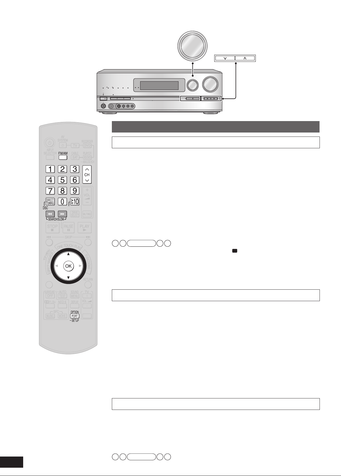
Listening to the Radio
WIRELESS READY
SURROUND M.ROOM
INPUT SELECTOR
VOLUME
+
_
MULTI CH
PROCESSING
TrueHD
D
+
DTS-HD
MULTI CH
LPCM
B
I-AMP
SETUP MIC
AUX
TUNE
RETURN
AUTO SPEAKER SETUP
-
SETUP
OK
SURROUND
SPEAKERS A
SPEAKERS B
S VIDEO
VIDEO
L - AUDIO - R
TUNE
INPUT SELECTOR
POWER
ENTER
SUB MENU
S
TV/VIDEO
Preset tuning
Auto presetting
1. Set the channel reception to FM 87.9 MHz (200 kHz steps) /
FM 87.5 MHz (100 kHz steps) or AM 520 kHz (➔ page 49).
• You can start with the frequency you like. In that case, stations with frequencies before
the starting point cannot be memorized.
• Up to 30 stations can be set in each band, FM and AM.
2. To enter the SETUP (➔ pa
3. Press [e][r] to select
Press [e][r] to select
4.
confirm.
5. Press [e][r] to select
• Select “CANCEL ” to cancel.
Note
• During automatic presetting, the memory indicator “M” lights up.
• “SET OK ” is displayed when automatic presetting is finished. Then, the previously tuned
station is displa
• Frequencies ma
weak. In such cases, carry out presetting manually.
• To cancel during automatic presetting, press [OK].
yed.
y not be preset correctly when broadcast waves are too strong or too
ge 36)
“TUNER ”, and press [OK] to confirm.
“AUTO MEMO ”, and press [OK] to
“START ”, and press [OK] to confirm.
48
RQT9223
Manual presetting
1. Tune to the station you want to preset (➔ pa
2. To enter the SETUP (➔ pa
3. Press [e][r] to select
Press [e][r] to select
4.
ge 36)
“TUNER ”, and press [OK] to confirm.
“MEMORY ”, and press [OK] to
confirm.
5. Press [e][r] to select a c
hannel to memorize, and press [OK]
to confirm.
• “STORED ” is displayed.
• To continue presetting, repeat the procedure from step 1.
6. To finish the setting (➔ pa
ge 36)
• FM stations can also be preset in the “MONO ” mode (➔ page 49).
Listening to preset stations (using the remote control)
1. Press [FM/AM] to select “FM ” or “AM ”.
Press [CH 1,
2.
Entering the channel number directly using the numbered buttons
■
To select a two digit channel number
e.g. 21: [≧10, ENTER] → [2] → [1]
Note
• You cannot operate this function on the unit.
2] to select a channel.
ge 49).

Manual tuning
“TUNED” is displayed when a station is tuned.
“ST” is displayed when a stereo FM broadcast is tuned.
Tuning directly using the numbered
buttons
Reducing excessive noise
During FM stereo reception
You can improve FM reception by switching reception to
monaural.
1. To enter the SETUP (➔ pa
ge 36)
1. Press [FM/AM] to activate the radio.
2. Press [FM/AM] to select “FM ” or “AM ”.
Press [DIRECT TUNING, DISC] to select
3.
Direct Tuning Mode.
4. Press the numbered buttons to enter the
frequency.
e.g. FM 107.9 MHz,
Press [DIRECT TUNING, DISC] → [1] → [0] → [7] → [9].
• If y
ou do not press a button while the cursor is flashing, the
display returns to the frequency being received.
• If the frequency has not been input correctly, “ERROR ” will be
displa
yed.
Using the unit
1. Turn [INPUT SELECTOR] to select “FM ”
or
“AM ”.
Press [TUNE 2 or 1] to tune in a station.
2.
Using the remote control
1. Press [FM/AM] to select “FM ” or “AM ”.
2.
Press [t] [y] to tune in a station.
2. Press [e][r] to select
“TUNER ”, and
press [OK] to confirm.
Press [e][r] to select
3.
“FM MODE ”, and
press [OK] to confirm.
Press [e][r] to select
4.
“MONO ”, and
press [OK] to confirm.
• When this is set, “MONO” appears on the display.
• Select “AUTO ” to cancel.
5. To finish the setting (➔ pa
During AM reception
When there is a lot of noise interference with an AM broadcast,
try switching to this mode.
1. To enter the SETUP (➔ pa
2. Press [e][r] to select
ge 36)
ge 36)
“TUNER ”, and
press [OK] to confirm.
Press [e][r] to select
3.
“BEAT PROOF ”,
and press [OK] to confirm.
4. Press [e][r] to select
“MODE 1 ” or
“MODE 2 ”, and press [OK] to confirm.
Factory setting: MODE 1
5. To finish the setting (➔ pa
ge 36)
Operations
Automatic tuning
g
Hold down [TUNE 2 or 1] on the unit or [t] [y] on the
remote control until the frequency begins to scroll.
• Tuning stops when a station is found.
• Tuning may stop if there is interference.
Note
• To cancel during auto tuning, press [TUNE 2 or 1] on the unit
or [t] [y] on the remote control.
Note
• Select “MODE 1 ” or “MODE 2 ” according to the improvement
of sound.
FM frequency step
If the correct FM frequency cannot be tuned in, change the
frequency step to suit your area.
1. To enter the SETUP (➔ pa
2. Press [e][r] to select
press [OK] to confirm.
Press [e][r] to select
3.
press [OK] to confirm.
Press [e][r] to select
4.
and press [OK] to confirm.
Factory setting: 200kHz
5. To finish the setting (➔ pa
Note
• When the frequency step is changed, the previously
memorized preset stations are initialised to the settings made
at the time of shipment.
ge 36)
“TUNER ”, and
“FM STEP ”, and
“100 ” or “200 ”,
ge 36)
Listening to the Radio
49
RQT9223

Other information
LEEP
PCM
DTS
96/24DTS
-ES
DIGITAL EX
EX
DIGITAL INPUT
kHz
MHz
ft
Notes on “To connect bi-wire
speakers”
Bi-wire speakers have separate connection terminals for high
frequency and low frequency signals (➔ page 22).
•
Bi-wiring prevents high frequency and low frequency signals
from interfering with each other. It offers playback in high
audio quality.
• HF and LF stand for high frequency and low frequency,
respectively.
Notes on “Using surround speakers
wirelessly with SH-FX67”
• Audio output changes as follows when you use surround
speakers wirelessly (➔ page 23).
- The maximum number of playback channels is 7.1. (2 sets
of SH-FX67 are necessary.)
- See SH-FX67’s operating instructions for setting surround
selector on SH-FX67 to enjoy 7.1ch playback.
To perform the auto speaker setup using the supplied
setup microphone
Insert digital transmitter before performing the setup.
Settings made with the setup microphone are cancelled
when y
ou insert or remove the transmitter after performing
the setup.
Digital signals that can be played on
this unit
• Depending on the connected equipment, the playback
condition differs. (Playback may be impossible if not
supported.)
See oper
information.
• See “Glossary” (➔ page 52) f
each signal.
Dolby Digital (including Dolby Digital
DTS (including DTS-ES, DTS 96/24 and
PCM (2-channel)
• This unit’s HDMI terminals and COAXIAL DIGITAL IN terminal
can pla
can pla
• Frequencies appear on the display when the unit receives
input signals tr
96 kHz, 176.4 kHz, and 192 kHz
.
Multi-channel LPCM (Linear PCM)
• When you make HDMI connections, the multi-channel LPCM
signal can be played back up to 192 kHz.
ating instructions of playback equipment for more
or more detailed information on
ound EX, Dolby Digital + and Dolby
Surr
TrueHD)
Blu-ray disc, DVD etc.
DTS-HD)
Blu-ray disc, DVD etc.
CD, DVD audio etc.
y up to 192 kHz and OPTICAL DIGITAL IN terminals
y up to 96 kHz.
ansmitted at the frequencies of 88.2 kHz,
Blu-ray disc, DVD audio etc.
Audio signal displays
DIGITAL
Dolby Digital decoder is being used.
DIGITAL EX
Dolby Digital EX decoder (Dolby Pro Logic
used when the input signal is Dolby Digital 5.1-channel or Dolby
Digital EX.
(Displayed only when you connect one surround back speaker.)
EX
Dolby Digital EX decoder (Dolby Pro Logic decoder) is being
used when the input signal is DTS 5.1-channel.
(Displayed only when you connect one surround back speaker.)
PL
Dolby Pro Logic decoder is being used.
PL
The display informs Dolby Pro Logic (the Dolby Pro Logic
decoder) is used on 2-channel stereo sources when surround
bac
k speakers are absent.
DTS
DTS decoder is being used.
DTS 96/24
DTS 96/24 decoder is being used.
DTS-ES
DTS-ES
NEO:6
DTS
SFC
SFC
decoder is being used.
NEO:6 decoder is being used.
matrix function is being used.
decoder) is being
Notes on “AUTO SPEAKER SETUP”
• Speaker placement, speaker directions and other conditions
may prevent correct setting.
• The unit sets the lowpass filter frequency at the value of the
speaker capable of reproducing the lowest frequency signal
among speakers judged as “SMALL ”.
•
When left and right speakers differ in size, they are set as
“SMALL ”.
•
When surround speakers and surround back speakers differ
in size, they are set as “SMALL ”.
•
Left and right front speakers are set as “LARGE ” even if their
siz
e is “SMALL ” when you perform the auto speaker setup
without connecting the subw
• The unit does not detect or correct polarity of left and right
front speakers when you select “YES ”
setting” (➔ page 38).
•
HDAVI Control (➔ page 32) does not work during the auto
speak
er setup.
• The auto speaker setup is unavailable while muting
(➔ page 31) is on.
•
The unit sets at 15 meters (45 feet) the distance of speakers
located more than 15 meters (45 feet) away from the seating
area. The set distance is displayed as “OVER ” (➔ page 37).
•
Speakers whose polarity was automatically adjusted are
displayed with “– ”
such as “L 3.0 – ” (➔ page 37).
oofer.
in “Making bi-wire
50
RQT9223

Notes on Speaker size
LARGE
Speakers that can sufficiently reproduce enough bass range.
SMALL
Speak
ers that do not satisfy the requirements for LARGE
speakers. Enough bass range can be produced, if you install
the subwoofer.
You can perform steps instructed in “Setting speakers and their
sizes” (➔ page 37) to change speak
er sizes set automatically.
Notes on Lowpass filter
• When the speaker size is “SMALL ”, the unit cannot
sufficiently reproduce the bass range.
• You can set the lowpass filter frequency according to the
playback frequency range and arrange the unit to output the
missing bass range from the subwoofer.
Note for speaker detection and size
setting
When you set the front speakers (“L ”, “R ”) as “LARGE ”
•
The subwoofer also makes audio output in the bass range when
you perform stereo playback of analog and PCM sources.
• The subwoofer sends out only the LFE (low frequency
effect channel) signal contained in 2-channel Dolby
Digital or DTS sources when you play them in stereo.
• The following are set automatically.
W
hen you set “LR ” to “SMALL”, “SUBW ” is set to “YES ”.
W
hen you set “SUBW ” to “NO ”, “LR ” is set to “LARGE ”.
• “SB ” does not appear when “S ” is set to “NONE ”.
• The “SB ” size becomes the “S ” size because the unit
does not off
• When you change the number of connected speakers,
settings made with the setup microphone are cancelled
(➔ pages 24 and 25).
• See “Notes on Speaker size” (➔ left) f
er “SB ” size setting.
or more details.
Notes on “SPEAKERS B”
• Playback is in 2-channel stereo when you select SPEAKERS
B only.
•
If a surround source is played back when only SPEAKERS B
is selected,
•
Selected speakers output sounds assigned to front 2
channels when you make ANALOG 8CH connections.
• If you select SPEAKERS B only, the following are set
automatically irrespectiv
speakers and their sizes” (➔ page 37).
Speaker size: “LARGE ”
Subwoofer: “NO ” (Bass is output from the front speakers.)
•
Settings made through the auto speaker setup (➔ pages 24
and 25) are cancelled.
“2CH MIX” is displayed on the display.
e of settings selected in “Setting
Notes on “BI-AMP”
This function activates automatically when you play analog
audio sources or 2-channel PCM signals through bi-wire
connections
• The unit takes advantage of the front speaker and the
surround back speaker amps, and drives the speakers’ highfrequency and low-frequency ranges separately when this
function is on.
• Press [SURROUND] off (➔ page 29).
• You cannot use BI-AMP with analog 8-channel connections.
•
The “BI-AMP” indicator stays on while BI-AMP is at work
(➔ page 6).
This unit
Front left (L)
Surround left (LS)
Surround bac
Front right (R)
Surround right (RS)
Surround back right (SBR)
Bi-wire speakers
.
Front left (L)
k left (SBL)
Front right (R)
Notes on “Playing an iPod on this
unit”
Compatible iPod for this unit
Name Memory size
iPod touch 8 GB, 16 GB
iPod nano 3rd generation (video) 4 GB, 8 GB
iPod classic 80 GB, 160 GB
iPod nano 2nd generation
(aluminum)
iPod 5th generation (video) 60 GB, 80 GB
iPod 5th generation (video) 30 GB
iPod nano 1st generation 1 GB, 2 GB, 4 GB
iPod 4th generation (color
display)
iPod 4th generation (color
display)
iPod 4th generation 40 GB
iPod 4th generation 20 GB
iPod mini 4 GB, 6 GB
* Compatible iPod correct as of May 2008.
Note
• Compatibility depends on the software version of your iPod.
• Audio/video cannot be recorded or transmitted to iPods or
vice versa via this unit.
• Panasonic makes no warranty over iPod data management.
• For more information, refer to the operating instructions for
iPod.
• The contents of the operating instructions and those displayed
on iPod may differ partially, but this will not fundamentally
affect use of music playback.
2 GB, 4 GB, 8 GB
40 GB, 60 GB
20 GB, 30 GB
Reference
Other information
Note for analog 8-channel
connections
Make the setting on equipment that matches the Blu-ray Disc/
DVD player.
51
RQT9223

Glossary
Analog
Audio signals produced from L/R audio output terminals of
general equipment is called analog audio.
CPPM (Content Protection for Prerecorded
Media)
This is the copyright protection technology which prevents file
copy of DVD audio.
Decoder, Decode
Decoder is the device to enable us to hear audio data that is
encoded on DVD, etc., as a normal audio signal. This process
is called Decode.
Deep Color
This unit incorporates HDMI™ (V.1.3 with Deep Color)
technology that can reproduce greater color gradation (4096
steps) when connected to a compatible TV.
You can enjoy exceptionally rich, natural-looking colors, with
smooth, detailed gradation and minimal color banding.
[A lower color gradation (256 steps), without deep color, will be
reproduced if connected to a TV which does not support deep
color.]
Digital
DVD recorders, Blu-ray Disc/DVD players, and CD players are
usually equipped with digital output terminals. Connect through
the digital terminal to enjoy digital surround systems such as
Dolby Digital and DTS.
Dolby Digital
Digital audio compression technology developed by Dolby
Laboratories, Inc. Compatible with surround sound as well as
2-channel stereo sound. With this technology, you can keep
massive amount of audio data efficiently.
Dolby Digital +
Improved version of Dolby Digital. It offers higher-audio
quality, support for multi-channel (5.1-channel and more) and
increased bitrates.
Dolby Digital Surround EX
Improved version of Dolby Digital. You can playback 6.1-channel
sound by adding surround center to 5.1-channel compatible
with Dolby Digital.
Dolby Pro Logic
This technology converts any 2-channel source recorded
including Dolby surround into 5.1/7.1 or 6.1-channel sound with
more realistic sound effects. You can enjoy old movies recorded
in conventional 2-channel sounds (excluding monaural sounds)
as they are converted to dynamic 5.1/7.1 or 6.1-channel sound.
/Dolby Pro Logic
x
Dolby TrueHD
Dolby TrueHD is an advanced version of MLP lossless method
used for DVD audio. This is a high-quality audio method which
enables complete playback of audio data made through a
mastering studio.
Dolby TrueHD can only be used for Blu-ray Disc, etc, but is not
applicable to DVD audio format.
DTS (Digital Theater Systems)
Surround system used in most movie theaters. Separation
works well between channels, resulting in realistic surround
effects.
DTS 96/24
This is higher-quality DTS with 96 kHz/24 bit and used for
DVD-Video. 48 kHz/24 bit playback is possible on systems
incompatible with DTS 96/24 due to backward compatibility.
DTS-ES
Improved version of DTS. You can playback 6.1-channel sound
by adding surround center to 5.1-channel.
DTS-HD
Audio technology enhanced in sound quality and functions
based on DTS (used at movie theaters). You can playback
DTS-HD sound as DTS on conventional AV amplifiers due to
backward compatibility.
Depending on the encoding methods and bitrates, DTS is
classified into three types: DTS-HD Master Audio, DTS-HD
High Resolution Audio and DTS Digital Surround.
The format itself supports up to 2048 channels, but the
maximum number of channels for next-generation DVD (Blu-ray
Disc, etc.) is 8ch (7.1ch).
Dynamic range
Dynamic range is the difference between the lowest level of
sound that can be heard above the noise of the equipment and
the highest level of sound before distortion occurs.
HDMI (High Definition Multimedia Interface)
HDMI enables you to transmit digital audio and video signals
using a single cable.
You can also transmit control signals using HDMI connections.
LPCM (Linear PCM)
This is one of the PCM methods and the uncompressed audio
signal encoded digitally. This method is used for music CD, etc.
Multi-channel LPCM signals used for Blu-ray Disc, DVD audio,
etc. enable playback with higher-sound quality.
Optical
Using optical fiber cable for digital signal input/output from
DVD, CD, etc., provides better sound quality for playback or
recording compared to analog.
PCM (Pulse Code Modulation)
This is one of the methods that enables analog sounds to be
converted to digital sounds.
Sampling frequency
Sampling is the process of converting the heights of sound
wave (analog signal) samples taken at set periods into digits
(digital encoding).
Sampling frequency is the n
second, so larger numbers mean faithful reproduction of the
original sound.
umber of samples taken per
Surround signal
Audio signal made up with front speakers, center speaker and
surround speakers.
x.v.Color
This is a name of products compliant with ISO Standard for
wider color space: “xvYCC”.
1080p
This is one of the digital hi-vision images.
1080 is the number of effective scanning lines that constitute
the actual screen. This enables every detail to be beautifully
expressed. Images are less flickered with progressive method
that scans in order from the top.
52
RQT9223

Error messages
Message Cause/countermeasure
U701
1
U703
2
U704
3
REMOTE 1
or
4
REMO
TE 2
CANCEL MUTING
5
FUNCTION
NO C AND LS/RS
6
SPEAKERS
NO LS/RS
7
SPEAKERS
The equipment connected by the HDMI cable is not compatible with the unit’s copyright
protection technology.
Should anything unusual happen using an HDMI connection:
Consult your dealer if the sign remains on the display after these steps.
• Turn the connected equipment off and on again.
• Pull out the HDMI cable then reinsert it.
• Reduce the number of equipment connected in series to the HDMI terminal if exceeding 2
units
.
The unit has received a signal for a picture format that is incompatible with the HDMI connection.
Check the settings of the connected equipment.
Match the modes on the main unit and the remote control.
Muting is on.
Press [MUTING] on the remote control to cancel the function (➔ page 31).
Center and surround speak
Surround speak
ers are set as absent. Change their setting to present (➔ page 37).
ers are set as absent. Change their setting to present (➔ page 37).
NO LS/RS AND SBL/
8
SBR SPEAKERS
NO SBL/SBR
9
SPEAKERS
NOT POSSIBLE FOR
10
ANALOG 8CH INPUT
NOT POSSIBLE FOR
11
THIS INPUT SOURCE
PCM FIX
12
(flashing)
SELECT SPEAKER A “SPEAKERS A” is off. Select “SPEAKERS A” (➔ page 26).
13
SPEAKERS ARE OFF
14
NOT SUPPORT FOR
THIS WIRELESS
15
SYSTEM
Surround and surround bac
(➔ page 37).
Surround bac
Y
ou are trying to use the effect unavailable for analog 8-channel playback.
Y
ou are trying to use the effect unavailable for the current input source.
The unit is in the “PCM FIX” mode
“SPEAKERS A” and “SPEAKERS B” are off. Select “SPEAKERS A” or “SPEAKERS B”
(➔ pages 26 and 27).
Not compatib
k speakers are set as absent. Change their setting to present (➔ page 37).
le with this wireless system (➔ page 23).
k speakers are set as absent. Change their setting to present
. Cancel this mode (➔ page 39).
Reference
Glossary / Error messages
53
RQT9223

Troubleshooting guide
Before requesting service, make the following checks. If you are in doubt about some of the check points, or if the remedies
indicated in the chart do not solve the problem, refer to “Customer Services Directory” on page 57 if you reside in the U.S.A., or
refer to “Product information” on page 59 if you reside in Canada.
Pages
No power. • Ensure the AC power supply cord is connected. 12
• Check that the volume is adequate.
•
Select either “SPEAKERS A ” or “SPEAKERS B ” if the speakers indicator is off.
• Select the correct input source.
• Cancel the “MUTING ” function.
No sound.
Sound is distor
Sound stops.
“F61 ” appears on the display
or about a second, and the unit
f
turns off.
“F76 ” appears on the display
and the unit turns off
“F70 ” appears on the display.
y is dim. • Cancel “DIMMER”. 37
Displa
Clic
king sound is heard during
play.
“MEASURING ERROR ” appears
on the displa
When speaker distances are set
(➔ pa
ge 37), “–” appears on the
y with the speaker name
displa
such as “L 3.0 – ”.
When speaker distances are set
(➔ pa
ge 37), “OVER ” appears
on the display.
Sound is not hear
center, surround or subwoofer
speakers.
Sound is not heard from the
surround back speaker.
Dolby Pro Logic
SFC are unavailable.
There is no DTS audio output.
There is audio output,
DTS decoder indicator is not lit.
The radio cannot be tuned in
or there is a lot of noise and
erence.
interf
ted.
.
y.
d from the
, NEO:6, and
but the
• Check that the signals can be decoded by this unit.
• Check connections to speakers and other equipment.
• Check that the input setting suits the type of connection you have made.
• Cancel the PCM FIX.
• Recording of some DVD-Audio may not be possible to be played due to
copyright protection.
• Check that ( and ) of speak
• Check that speaker impedance is lower than tolerance of the unit.
• Straining of the speakers through excessive volume or power.
• This may occur if you use the unit in an extremely hot environment.
• Curtains or other objects may be blocking the exhaust hole.
Determine and correct the cause, then turn the unit on.
(The protection circuit is reset.)
(Consult y
• Turn the unit off, disconnect the AC power supply cord, and consult your
dealer.
•
Turn the unit off, disconnect the AC power supply cord, and consult your
dealer.
• Depending on the input signal when playing DVD etc., the BI-AMP
function changes automatically. A clicking sound is heard when it changes.
This does not mean a problem with the unit.
• A speaker is too far. Check speaker locations.
• An error occurred from a cause that cannot be identified. Perform the auto
speaker setup again.
•
It appears when polarity of a speaker is automatically adjusted.
You can set speakers against automatic polarity adjustment.
➔
• It appears when the measured distance exceeds 15 meters (45 feet).
Check the speaker location.
• Ensure the speaker settings for your speakers are correct.
• Confirm Dolby Pro Logic
adequate mode.
• Press [SURROUND] on when you play 2-channel stereo sources.
• Ensure the speaker settings for your speakers are correct.
• Press [SURROUND] on.
• Check if the center speaker, surround speakers, and surround back
speakers are connected properly.
• Press [SPEAKERS A] on.
• Cancel ANALOG 8CH playback.
• You cannot use the effect when the input source contains dual audio
signals in Dolby Digital or DTS formats.
•
Set the DTS Digital Audio Output setting on the Blu-ray Disc/DVD player
or DVD recorder to “Bitstream”.
•
Connect the appropriate antenna. (You may need an outdoor antenna or one with more elements.)
• Adjust the position of the FM or AM antenna.
• Reduce the treble.
• Turn off nearby televisions, video decks, DVD recorders, Blu-ray Disc/DVD
players, and satellite receivers.
• Separate the antenna from other cables, cords, and appliances.
our dealer if the problem persists.)
er cable is interfering each other.
, NEO:6, or SFC settings, and select an
15, 26
24, 26, 27
15, 26
31
50
10 to 13, 16 to 23
39
39
–
10
10,
22
–
–
–
–
–
–
24, 25
–
38
–
24, 25, 37
28 to 30
13,
29
24, 25, 37
13, 29
10, 11
26
27
–
–
23
23
34
–
–
54
RQT9223

There is a lot of noise when
listening to AM.
The correct FM frequenc
cannot be tuned in.
When using an HDMI
connection,
seconds of sound is cut off.
The unit does not work properly.
VIERA Link does not function
pr
operly.
When more than one piece
of equipment are connected
to HDMI input terminal,
of them turn on and off
automaticall
The remote control doesn’t work.
Other products respond to the
remote control.
the first few
y.
y
some
Pages
•
Try changing the BEAT PROOF mode. 49
•
Change the frequency step to suit your area when FM is selected. 49
• Should you be playing a chapter on a DVD etc.:
– Change the audio output setting on the Blu-ray Disc/DVD player or
DVD recorder from “Bitstream” to “PCM”. (6.1-channel sources will
however be played as 5.1-channel
– Select “PCM ” as instructed in “Setting input signals” when you play
2-channel stereo sources.
• The unit does not work properly when wrong cords are in HDMI input and
output terminals. Turn the unit off, unplug the AC power supply cord, and
make connections again.
• Confirm “Setting VIERA Link to “OFF ””
change to “ON ”.
•
VIERA Link does not function in power saving standby mode when this
unit is turned off. See “Reducing standby power consumption (power save
mode)” and set to “ON ”
• Check VIERA Link settings of the connected equipment.
• VIERA Link may not function when you change the connections for HDMI
equipment, insert and remove the outlet, or during blackout. Do the
following operations in this case.
–
Turn the TV (VIERA) on again while all the equipment connected with
HDMI cables are on.
– Set “VIERA Link (HDMI equipment control)” of TV (VIERA) to “OFF” and
then set to “ON” again. (For details, refer to the operating instructions for
TV (VIERA).)
– Connect this unit to
(VIERA) on, unplug this unit’s AC power supply cord, and insert it into a
household A
• Some of the linked operations apply to the connected equipment that is
VIERA Link compatible. To prevent this, set the connected equipment (DVD
recorder (DIGA) and others) against VIERA Link.
• Replace the batteries if they are worn. 7
• Change this unit’s remote control mode to “REMOTE 2 ”. 42
C outlet again.
(normal power consumption).
TV (VIERA) using the HDMI cable, switch the TV
.)
is set to “ON ”. When it is “OFF ”,
39
12, 13, 16
40
40
–
–
–
Reference
–
Maintenance
Unplug the AC power supply cord from the household AC outlet and wipe the unit using a soft and dry cloth.
When the unit is very dirty, wring the cloth soaked in water thoroughly, wipe the dirt and wipe moisture off with a dry cloth.
•
Do not use solvents such as benzine, thinner, alcohol, etc. because they may cause casing to deform and coating to go off.
•
Before using chemically treated cloth, read the instructions that come with the cloth carefully.
•
Troubleshooting guide / Maintenance
55
RQT9223

Specifications
AMPLIFIER SECTION
g
Rated minimum sine wave RMS power output
20 Hz - 20 kHz both channels driven (with AES17 filter)
0.7 % total harmonic distortion 130 W per channel (6 Ω)
Total harmonic distortion
rated power at 20 Hz - 20 kHz 0.7 % (6 Ω)
Power output each channel driven at 20 Hz - 20 kHz
(with AES17 filter)
0.7 % total harmonic distortion
Front (L/R) 130 W (6 Ω)
Center 130 W (6 Ω)
Surround (L/R) 130 W (6 Ω)
Surround Back (L/R) 130 W (6 Ω)
Load impedance
Front (L/R)
A or B 4 to 8 Ω
A and B 6 to 8 Ω
BI-WIRE 4 to 8 Ω
Center 6 to 8 Ω
Surround (L/R) 6 to 8 Ω
Surround Back (L/R) 6 to 8 Ω
Frequency response
CD, AUX, TV, GAME, CABLE/SAT, VCR,
DVD RECORDER, BD/DVD PLAYER /
ANALOG 8CH IN, OPTION PORT 4 Hz to 40 kHz, ±2 dB
Input sensitivity and impedance
CD, AUX, TV, GAME, CABLE / SAT, VCR,
DVD RECORDER, BD/DVD PLAYER /
ANALOG 8CH IN, OPTION PORT 16 mV (200 mV, IHF'66) 22 kΩ
Subwoofer frequency response (-6 dB) 7 Hz to 200 Hz
S/N (IHF A)
CD, TV, BD/DVD PLAYER,
DVD RECORDER (Digital Input) 97 dB, IHF'66
Tone controls
BASS 50 Hz, +10 to -10 dB
TREBLE 20 kHz, +10 to -10 dB
Output voltage
DVD RECORDER 200 mV
Digital input (OPTICAL) 3
(COAXIAL) 1
GENERAL
g
Power supply AC 120 V, 60 Hz
Power consumption 150 W
Dimensions (W x H x D) 430 mm x 158.5 mm x 339 mm
(16-15/16" x 6-1/4" x 13-11/32")
Mass (Weight) Approx. 5 kg (11 lb.)
Operating temperature range 0°C to 40°C
(32°F to 104°F)
Operating humidity range 20% to 80% RH (no condensation)
Power consumption in standby mode: 0.7 W
Power consumption in HDMI off mode: 0.4 W
Notes:
1. Specifications are subject to change without notice.
2. Total harmonic distortion is measured by the digital spectrum
analyzer.
HDMI Input (Corresponding Deep Color) 3
Output (Corresponding Deep Color) 1
This unit supports “HDAVI Control 3” function.
FM TUNER SECTION
g
Frequency range 87.9 to 107.9 MHz (200 kHz steps)
87.5 to 108.0 MHz (100 kHz steps)
Sensitivity 11.2 dBf (2 µV, IHF'58)
Total harmonic distortion
MONO 0.5 %
STEREO 0.7 %
S/N
MONO 73 dB
STEREO 67 dB
Alternate channel selectivity 65 dB
Antenna terminal 75 Ω (unbalanced)
AM TUNER SECTION
g
Frequency range 520 to 1710 kHz
OPTION PORT SECTION
g
An exclusive terminal for SH-PD10 (option) 1
VIDEO SECTION
g
Output voltage at 1 V input (unbalanced) 1±0.1 Vp-p
Maximum input voltage 1.5 Vp-p
Input/output impedance 75 Ω
Composite Video Input BD/DVD PLAYER, DVD RECORDER,
VCR, CABLE/SAT, GAME, AUX
Output DVD RECORDER, TV MONITOR
S-Video Input BD/DVD PLAYER, DVD RECORDER,
VCR, CABLE/SAT, GAME, AUX
Output DVD RECORDER, TV MONITOR
Component Video Input BD/DVD PLAYER, DVD RECORDER,
CABLE/SAT
56
Output TV MONITOR
RQT9223

Limited Warranty (Only for the U.S.A.)
Panasonic Consumer Electronics Company,
Division of Panasonic Corporation of North America
One Panasonic Way Secaucus, New Jersey 07094
Panasonic Audio Products Limited Warranty
Limited Warranty Coverage
If your product does not work properly because of a defect in materials or
workmanship, Panasonic Consumer Electronics Company or Panasonic Puerto
Rico, Inc. (collectively referred to as “the warrantor”) will, for the length of
the period indicated on the chart below, which starts with the date of original
purchase (“warranty period”), at its option either (a) repair your product with new
or refurbished parts, or (b) replace it with a new or a refurbished product. The
decision to repair or replace will be made by the warrantor.
Product or Part Name Parts Labor
Audio Products (except items listed below)
USB Reader-Writer, Personal Computer
Card Adapters
(in exchange for defective item)
Accessories: Headphones, Cartridges,
Microphones, Adapters
Rechargeable Batteries, DVD-R/-RAM
Discs (in exchange for defective item)
SD Memory Cards, Rechargeable Battery
Packs (in exchange for defective item)
During the “Labor” warranty period there will be no charge for labor. During the
“Parts” warranty period, there will be no charge for parts. You must carry-in or
mail-in your product during the warranty period. If non-rechargeable batteries
are included, they are not warranted. This warranty only applies to products
purchased and serviced in the United States or Puerto Rico. This warranty is
extended only to the original purchaser of a new product which was not sold “as
is”. A purchase receipt or other proof of the original purchase date is required for
warranty service.
One (1) year One (1) year
One (1) year Not Applicable
Ninety (90) days Ninety (90) days
Ten (10) days Not Applicable
Ninety (90) days Not Applicable
Panasonic Puerto Rico, Inc.
Ave. 65 de Infantería, Km. 9.5
San Gabriel Industrial Park, Carolina, Puerto Rico 00985
Carry-In or Mail-In Service
For Carry-In or Mail-In Service in the United States call 1-800-211-PANA (1-800211-7262) or visit Panasonic web site: http://www.panasonic.com
For assistance in Puerto Rico call Panasonic Puerto Rico, Inc. (787)-750-4300 or
fax (787)-768-2910.
Limited Warranty Limits And Exclusions
This warranty ONLY COVERS failures due to defects in materials or
workmanship, and DOES NOT COVER normal wear and tear or cosmetic
damage. The warranty ALSO DOES NOT COVER damages which occurred in
shipment, or failures which are caused by products not supplied by the warrantor,
or failures which result from accidents, misuse, abuse, neglect, mishandling,
misapplication, alteration, faulty installation, set-up adjustments, misadjustment
of consumer controls, improper maintenance, power line surge, lightning
damage, modification, or commercial use (such as in a hotel, office, restaurant,
or other business), rental use of the product, service by anyone other than a
Factory Servicenter or other Authorized Servicer, or damage that is attributable
to acts of God.
THERE ARE NO EXPRESS WARRANTIES EXCEPT AS LISTED UNDER
“LIMITED WARRANTY COVERAGE”. THE WARRANTOR IS NOT LIABLE
FOR INCIDENTAL OR CONSEQUENTIAL DAMAGES RESULTING FROM
THE USE OF THIS PRODUCT, OR ARISING OUT OF ANY BREACH OF
THIS WARRANTY. (As examples, this excludes damages for lost time, travel
to and from the servicer, loss of media or images, data or other memory
content. The items listed are not exclusive, but are for illustration only.) ALL
EXPRESS AND IMPLIED WARRANTIES, INCLUDING THE WARRANTY
OF MERCHANTABILITY, ARE LIMITED TO THE PERIOD OF THE LIMITED
WARRANTY.
Some states do not allow the exclusion or limitation of incidental or consequential
damages, or limitations on how long an implied warranty lasts, so the exclusions
may not apply to you. This warranty gives you specific legal rights and you
may also have other rights which vary from state to state. If a problem with this
product develops during or after the warranty period, you may contact your
dealer or Servicenter. If the problem is not handled to your satisfaction, then write
to the warrantor’s Consumer Affairs Department at the addresses listed for the
warrantor.
PARTS AND SERVICE WHICH ARE NOT COVERED BY THIS LIMITED
WARRANTY ARE YOUR RESPONSIBILITY.
Reference
Customer Services Directory
Obtain Product Information and Operating Assistance; locate your nearest Dealer or Servicenter; purchase Parts and Accessories; or make
Customer Service and Literature requests by visiting our Web Site at:
http://www.panasonic.com/consumersupport
or, contact us via the web at:
http://www.panasonic.com/contactinfo
You may also contact us directly at: 1-800-211-PANA (7262),
Monday-Friday 9 am-9 pm; Saturday-Sunday 10 am-7 pm, EST.
For hearing or speech impaired TTY users, TTY: 1-877-833-8855
Accessory Purchases
Purchase Parts, Accessories and Instruction Books online for all Panasonic Products by visiting our Web Site at:
http://www.pstc.panasonic.com
or, send your request by E-mail to:
npcparts@us.panasonic.com
You may also contact us directly at: 1-800-332-5368 (Phone) 1-800-237-9080 (Fax Only)
(Monday - Friday 9 am to 9 pm, EST.) Panasonic Service and Technology Company
20421 84th Avenue South, Kent, WA 98032 (We Accept Visa, MasterCard, Discover Card, American Express, and Personal Checks)
For hearing or speech impaired TTY users, TTY: 1-866-605-1277
Service in Puerto Rico
Panasonic Puerto Rico, Inc.
Ave. 65 de Infantería, Km. 9.5, San Gabriel Industrial Park, Carolina, Puerto Rico 00985
Phone (787)750-4300, Fax (787)768-2910
Specifications / Limited Warranty (Only for the U.S.A.)
57
RQT9223

Limited Warranty (Only for Canada)
Panasonic Canada Inc.
PANASONIC PRODUCT – LIMITED WARRANTY
Panasonic Canada Inc. warrants this product to be free from defects in material and workmanship and agrees to remedy any such defect for a
period as stated below from the date of original purchase.
Technics Audio Product One (1) year, parts and labour
Panasonic Portable / Clock Radio (without Tape, CD, MD) One (1) year, parts and labour
Panasonic Audio / SD Audio Product One (1) year, parts and labour
Panasonic DVD Product One (1) year, parts and labour
Panasonic Combination DVD Player / VCR One (1) year, parts and labour
Panasonic Combination DVD Recorder / VCR One (1) year, parts and labour
Accessories including rechargeable batteries Ninety (90) days
LIMITATIONS AND EXCLUSIONS
This warranty does not apply to products purchased outside Canada or to any product which has been improperly installed, subjected to usage for
which the product was not designed, misused or abused, damaged during shipping, or which has been altered or repaired in any way that affects
the reliability or detracts from the performance, nor does it cover any product which is used commercially. Dry cell batteries are also excluded from
coverage under this warranty.
This warranty is extended to the original end user purchaser only. A purchase receipt or other proof of date of original purchase is required before
warranty service is performed.
THIS EXPRESS, LIMITED WARRANTY IS IN LIEU OF ALL OTHER WARRANTIES, EXPRESS OR IMPLIED, INCLUDING ANY IMPLIED
WARRANTIES OF MERCHANTABILITY AND FITNESS FOR A PARTICULAR PURPOSE.
IN NO EVENT WILL PANASONIC CANADA INC. BE LIABLE FOR ANY SPECIAL, INDIRECT OR CONSEQUENTIAL DAMAGES.
In certain instances, some jurisdictions do not allow the exclusion or limitation of incidental or consequential damages, or the exclusion of implied
warranties, so the above limitations and exclusions may not be applicable.
WARRANTY SERVICE
FOR PRODUCT OPERATION ASSISTANCE, please contact:
Our Customer Care Centre: Telephone #: (905) 624-5505
1-800 #: 1-800-561-5505
Fax #: (905) 238-2360
Email link: “Customer support” on www.panasonic.ca
FOR PRODUCT REPAIRS, please locate your nearest Authorized Servicentre at www.panasonic.ca :
Link : “ServicentresTM locator” under “Customer support”
IF YOU SHIP THE PRODUCT TO A SERVICENTRE
Carefully pack and send prepaid, adequately insured and preferably in the original carton.
Include details of the defect claimed, and proof of date of original purchase.
58
RQT9223

Product Service
1. Damage requiring service — The unit should be serviced by
qualified service personnel if:
(a) The AC power supply cord or the plug has been damaged; or
(b) Objects or liquids have gotten into the unit; or
(c) The unit has been exposed to rain; or
(d) The unit does not operate normally or exhibits a marked change
in performance; or
(e) The unit has been dropped or the cabinet damaged.
2. Servicing — Do not attempt to service the unit beyond that described
in these operating instructions. Refer all other servicing to authorized
servicing personnel.
3. Replacement parts — When parts need replacing ensure the
servicer uses parts specified by the manufacturer or parts that have
the same characteristics as the original parts. Unauthorized
substitutes may result in fire, electric shock, or other hazards.
4. Safety check — After repairs or service, ask the servicer to perform
safety checks to confirm that the unit is in proper working condition.
The servicer will require all components to service your system.
Therefore, should service ever be necessary, be sure to bring the entire
system.
Product information
For product information or assistance with product operation:
In the U.S.A., refer to “Customer Services Directory” on page 57.
In Canada, contact the Panasonic Canada Inc. Customer Care Centre
at 1-800-561-5505, or visit the website (www.panasonic.ca), or an
authorized Servicentre closest to you.
The model number and serial number of this product can be found on
either the back or the bottom of the unit.
Please note them in the space provided below and keep for future
reference.
MODEL NUMBER _______________________________________
SERIAL NUMBER _______________________________________
SA-BX500
User memo:
DATE OF PURCHASE __________________________________
DEALER NAME _______________________________________
DEALER ADDRESS ____________________________________
____________________________________________________________
TELEPHONE NUMBER _________________________________
Reference
59
RQT9223
Limited Warranty (Only for Canada) / Product Service

Panasonic Consumer Electronics
Company, Division of Panasonic
Corporation of North America
One Panasonic Way Secaucus,
New Jersey 07094
http://www.panasonic.com
Panasonic Puerto Rico, Inc.
Ave. 65 de Infantería, Km. 9.5
San Gabriel Industrial Park, Carolina,
Puerto Rico 00985
Panasonic Canada Inc.
5770 Ambler Drive
Mississauga, Ontario
L4W 2T3
www.panasonic.ca
60
RQT9223
© 2008 Matsushita Electric Industrial Co., Ltd.
Printed in Malaysia
 Loading...