

Thank you very much for using SUNX products.
SUNX
ON OFF
SUNX
ON OFF
SUNX
ON OFF
Please read this Instruction Manual carefully and
thoroughly for the correct and optimum use of this
INSTRUCTION MANUAL
High-Speed㨯High-Accuracy Eddy Current
Digital Displacement Sensor GP-X Series
BCD Output Unit
GP-XBCD
1
SPECIFICATIONS
Designation
Item
Power supply
Current consumption
Output
5-digit BCD output
Polarity indication output
VALID output
Input (Hold input)
Switch
Material
Weight
Accessory
Connection cable
(optional)
Note: When the controller communication unit (GP-XCOM) is used, and a different power supply is used for the 2, or more,
2
GP-XBCD GP-XCOM
No.
1
2
3
Notes1)2)To use the BCD output unit, make sure to configure
Model No.
controllers, be sure to connect either +V lines or 0V lines of the controllers each other.
PART DESCRIPTION
Description
Cable with connector on one end for
BCD output unit
(optional)
Connector for
BCD output
Connector for connecting the controller
the BCD output. For the setting method, refer to the
instruction manual enclosed with the GP-X series.
After the controller is configured for BCD output,
the analog voltage output becomes invalid.
Controller Communication Unit
GP-XCOM
BCD output unit
GP-XBCD
Supplied from controller (GP-XCغ) (Note)
20mA or less
N channel MOS FET open drain
Maximum sink current: 50mA
Applied voltage: 30V DC or less
Residual voltage: 1V or less (at 50mA sink current)
Non-voltage contact or NPN open-collector transistor
Low0 to 1V:
GP-XBCC3 (Exclusive cable3m)
2
1
Connect the BCD output unit.
Connect the cable with connector
on one end for BCD output unit.
Connect with the side panel of
the controller.
(between output and GND)
Valid, High (open): Invalid
㧙
30g approx.
Mounting bracket [stainless steel (SUS304)]㧦1 pc.
3
Function
product. Kindly keep this manual in a convenient
place for quick reference.
For the details of High-speed
㨯
high-accuracy
eddy current digital displacement sensor GP-X
series, refer to the instruction manual enclosed
with the GP-X series.
Controller communication unit
GP-XCOM
5mA or less
㧙
㧙
Terminator ON/OFF switch
Enclosure㧦ABS
20g approx.
SL-F150 (Cable length 150mm)
SL-F250 (Cable length 250mm)
SL-F1000 (Cable length 1,000mm)
21 35
4
No.
Description Function
Link cable
1
(optional)
Transmission
2
connector
Reception
3
connector
Terminator
4
switch
Connector for connec-
5
ting the controller
Connects between controller
communication units.
Connect a link cable to communicate
with another controller.
If only one link cable is
connected, turn this switch on.
(Lower side: ON)
Connect with the side panel of
the controller.
3
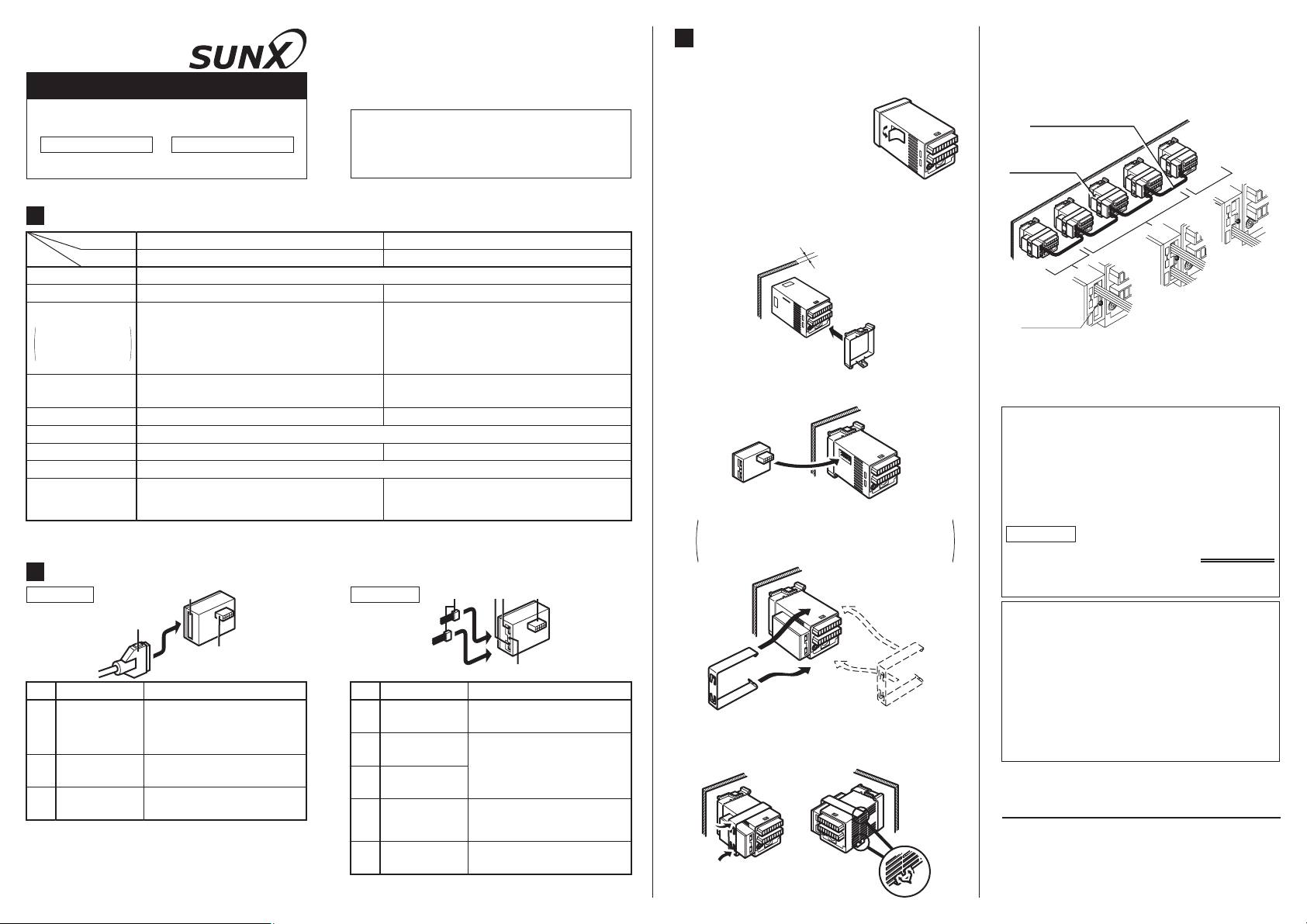
MOUNTING
٨
In order to mount the BCD output unit (GP-XBCD)
and
the controller communication unit (GP-XCOM) to
the controller, follow the procedures explained below.
Ԙ Peel off the side seal of the
controller.
ԙ Mount the controller and the mounting frame on
the panel in the orientation shown in the figure
below. For details, refer to the instruction
manual enclosed with the GP-X series.
1 to 2.5mm
Ԛ Mount GP-XBCD or GP-XCOM from the side.
ԛ Mount the mounting bracket from the side.
If the bracket interferes with another unit or
the like and it cannot be mounted sideways,
mount from the rear while opening its arms.
(Mounting from rear) (Mounting from side)
Press portions A of the mounting bracket to snap por-
Ԝ
tions B to fix the bracket, as shown in the figure below.
A
A
B
ԝ
Connect the GP-XCOM as shown in the figure
below. Turn the terminator switch on at the two
units located at the both ends of the network.
Turn the terminator switch off at the other units.
Link cable for controller
communication unit
SL-F150/F250/F1000
Controller
communication unit
(GP-XCOM)
Terminator
switch ON
Terminator
Terminator
switch ON
Ԟ
Turn the power ON.
ԟ
Carry out the BCD output setting or the address
switch OFF
setting. For details of the settings, refer to the
instruction manual enclosed with the GP-X series.
٨
Operating conditions for Compliance with CE
This is a CE conformity product complying
with EMC Directive. The harmonized standard
with regard to immunity that applies to this
product is EN 61000-6-2 and the following
condition must be met to conform to that
standard.
Condition
A ferrite clamp must be mounted within 10 mm
of the base of the cable with connector on one
end for BCD output unit (GP-XBCC3).
When GP-XCOM is used, controllers cannot
communicate if their software versions are not
compatible. Use a correct combination, as shown
below.
For conforming method of the software version,
refer to the instruction manual enclosed with the
GP-X series.
Ver. 1.06 or eariler version with Ver. 1.06 or earlier v ersion: P ossib le
Ver. 1.06 or eariler version with Ver. 1.10 or later version: Impossible
Ver. 1.10 or later version with Ver. 1.10 or later version: Possible
SUNX Limited
Head Office
2431-1 Ushiyama-cho, Kasugai-shi, Aichi, 486-0901, Japan
Phone: +81-(0)568-33-7211 FAX: +81-(0)568-33-2631
Overseas Sales Dept.
Phone: +81-(0)568-33-7861 FAX: +81-(0)568-33-8591
http://www.sunx.co.jp/
PRINTED IN JAPAN
 Loading...