

Page 1
Before attempting to connect or operate this product,
please read these instructions carefully and save this manual for future use.
No model number suffix is shown in these Operating Instructions.
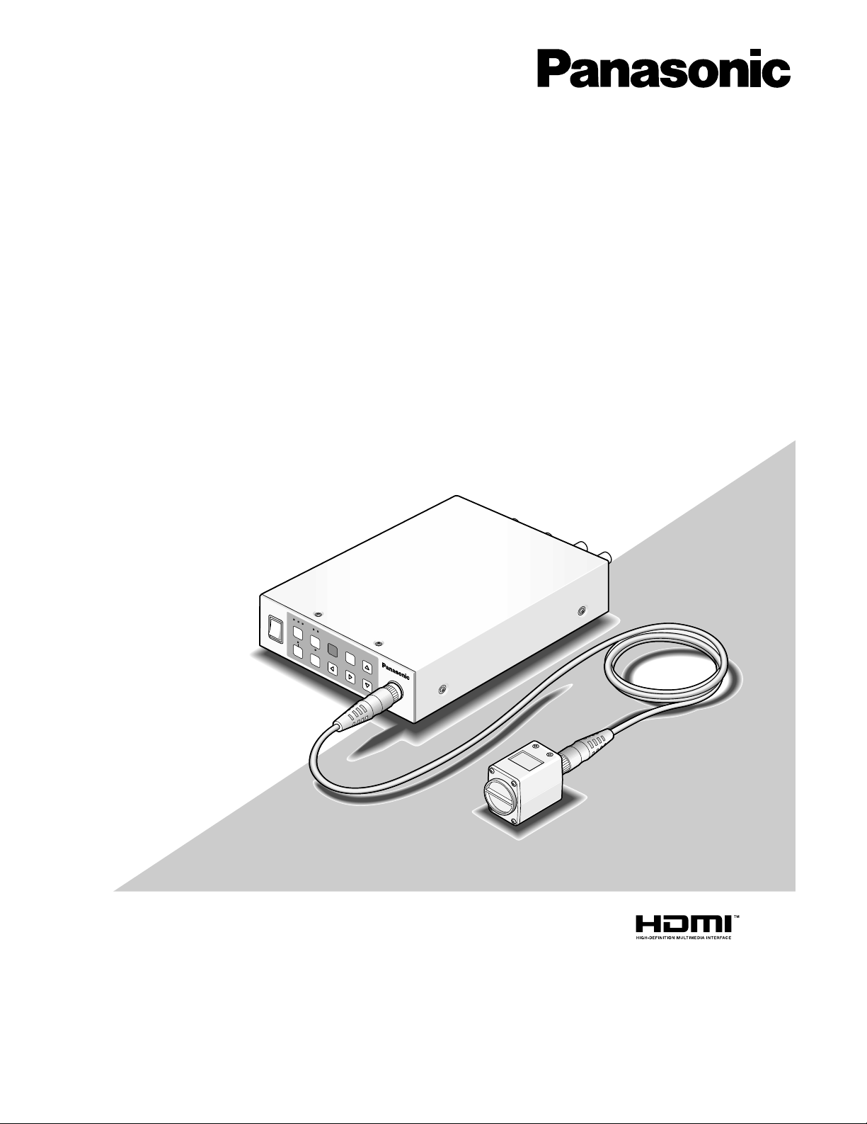
Operating Instructions
3CCD Color Camera CCU
Model Nos. GP-US932CU
GP-US932CUE
GP-US932CUS
GP-US932CUSE
Camera head: option
Camera cable: option
DC POWER
GP-US932
CAMERA
O
N
1
2
3
LO
W
S
C
E
N
E
B
A
R
A
W
C
G
A
IN
D
R
A
N
G
E
F
R
E
E
Z
E
M
E
N
U
S
E
L
H
IG
H
EXPA
ND
O
F
F
Page 2
2
NOTE: This equipment has been tested and found to comply with the limits for a Class A digital device, pursuant to
Part 15 of the FCC Rules. These limits are designed to provide reasonable protection against harmful interference
when the equipment is operated in a commercial environment. This equipment generates, uses, and can radiate
radio frequency energy and, if not installed and used in
accordance with the instruction manual, may cause harmful
interference to radio communications.
Operation of this equipment in a residential area is likely to
cause harmful interference in which case the user will be
required to correct the interference at his own expense.
FCC Caution: To assure continued compliance, (example use only shielded interface cables when connecting to computer or peripheral devices). Any changes or modifications
not expressly approved by the party responsible for compliance could void the user’s authority to operate this equipment.
For U.S.A
WARNING:
• To prevent fire or electric shock hazard, do not expose this
apparatus to rain or moisture.
• The apparatus should not be exposed to dripping or splashing
and that no objects filled with liquids, such as vases, should be
placed on the apparatus.
• All work related to the installation of this product should be made
by qualified service personnel or system installers.
• The connections should comply with local electrical code.
The lightning flash with arrowhead symbol,
within an equilateral triangle, is intended to
alert the user to the presence of uninsulated
"dangerous voltage" within the product's
enclosure that may be of sufficient magnitude to constitute a risk of electric shock to
persons.
CAUTION: TO REDUCE THE RISK OF ELECTRIC SHOCK,
DO NOT REMOVE COVER (OR BACK).
NO USER-SERVICEABLE PARTS INSIDE.
REFER SERVICING TO QUALIFIED SERVICE PERSONNEL.
CAUTION
RISK OF ELECTRIC SHOCK
DO NOT OPEN
CAUTION:
Before attempting to connect or operate this product, please
read the label on the bottom.
The exclamation point within an equilateral
triangle is intended to alert the user to the
presence of important operating and maintenance (servicing) instructions in the literature accompanying the appliance.
We declare under our sole responsibility that the product to which this
declaration relates is in conformity with the standards or other normative
documents following the provisions of Directives 2006/95/EC and
2004/108/EC.
Wir erklären in alleiniger Verantwortung, daß das Produkt, auf das sich
diese Erklärung bezieht, mit der folgenden Normen oder normativen
Dokumenten übereinstimmt. Gemäß den Bestimmungen der Richtlinie
2006/95/EC und 2004/108/EC.
Nosotros declaramos bajo nuestra única responsabilidad que el
producto a que hace referencia esta declaración está conforme con las
normas u otros documentos normativos siguiendo las estipulaciones de
las directivas 2006/95/CE y 2004/108/CE.
Noi dichiariamo sotto nostra esclusiva responsabilità che il prodotto a
cui si riferisce la presente dichiarazione risulta conforme ai seguenti
standard o altri documenti normativi conformi alle disposizioni delle
direttive 2006/95/CE e 2004/108/CE.
Nous déclarons sous note seule responsabilité que le produit auquel se
réfère la présente déclaration est conforme aux normes ou autres
documents normatifs conformément aux dispositions des directives
2006/95/CE et 2004/108/CE.
Wij verklaren als enige aansprakelijke, dat het product waarop deze
verklaring betrekking heeft, voldoet aan de volgende normen of andere
normatieve documenten, overeenkomstig de bepalingen van Richtlijnen
2006/95/EC en 2004/108/EC.
Vi erklærer os eneansvarlige for, at dette produkt, som denne
deklaration omhandler, er i overensstemmelse med standarder eller
andre normative dokumenter i følge bestemmelserne i direktivene
2006/95/EC og 2004/108/EC.
Vi deklarerar härmed värt fulla ansvar för att den produkt till vilken
denna deklaration hänvisar är i överensstämmelse med
standarddokument, eller andra normativa dokument som framställs i
direktiv nr. 2006/95/EC och 2004/108/EC.
Ilmoitamme yksinomaisella vastuullamme, että tuote, jota tämä ilmoitus
koskee, noudattaa seuraavia standardeja tai muita ohjeellisia asiakirjoja,
jotka noudattavat direktiivien 2006/95/EC ja 2004/108/EC säädöksiä.
Vi erklærer oss alene ansvarlige for at produktet som denne erklæringen
gjelder for, er i overensstemmelse med følgende normer eller andre
normgivende dokumenter som følger bestemmelsene i direktivene
2006/95/EC og 2004/108/EC.
The serial number of this product may be found on the surface of the unit.
You should note the model number and serial number of this
unit in the space provided and retain this book as a permanent record of your purchase to aid identification in the event
of theft.
Model No.
Serial No.
For U.S.A
Page 3

3
Important Safety Instructions
1) Read these instructions.
2) Keep these instructions.
3) Heed all warnings.
4) Follow all instructions.
5) Do not use this apparatus near water.
6) Clean only with dry cloth.
7) Do not block any ventilation openings. Install in accordance with the manufacturer's instructions.
8) Do not install near any heat sources such as radiators, heat registers, stoves, or other apparatus (including amplifiers) that
produce heat.
9) Do not defeat the safety purpose of the polarized or grounding-type plug. A polarized plug has two blades with one wider
than the other. A grounding type plug has two blades and a third grounding prong. The wide blade or the third prong are
provided for your safety. If the provided plug does not fit into your outlet, consult an electrician for replacement of the
obsolete outlet.
10) Protect the power cord from being walked on or pinched particularly at plugs, convenience receptacles, and the point
where they exit from the apparatus.
11) Only use attachments/accessories specified by the manufacturer.
12) Use only with the cart, stand, tripod, bracket, or table specified by the manufacturer, or sold with the apparatus. When a
cart is used, use caution when moving the cart/apparatus combination to avoid injury from tip-over.
13) Unplug this apparatus during lightning storms or when unused for long periods of time.
14) Refer all servicing to qualified service personnel. Servicing is required when the apparatus has been damaged in any way,
such as power-supply cord or plug is damaged, liquid has been spilled or objects have fallen into the apparatus, the
apparatus has been exposed to rain or moisture, does not operate normally, or has been dropped.
S3125A
Page 4

4
CONTENTS
Important Safety Instructions ............................................................................................................3
Limitation of Liability .........................................................................................................................5
Disclaimer of Warranty ......................................................................................................................5
Precautions .......................................................................................................................................6
Preface ..............................................................................................................................................8
Trademarks and Registered Trademarks .........................................................................................8
Major Operating Controls and Their Functions .................................................................................9
■ Camera head .............................................................................................................................9
■ Camera control unit (CCU) .........................................................................................................9
Installation/Connection ...................................................................................................................13
■ How to mount lens ....................................................................................................................14
Setting Procedures .........................................................................................................................15
■ SETUP menu ............................................................................................................................15
■ Basic operations ......................................................................................................................16
1. Camera title setting [CAMERA ID] .......................................................................................17
2. ELC setting [ELC] ................................................................................................................18
3. Electronic shutter setting [SHUTTER] ..................................................................................19
4. Gain adjustment [GAIN] ......................................................................................................19
5. Electronic sensitivity enhancement setting [SENS UP] .......................................................19
6. Output signal setting [OUTPUT SEL] ..................................................................................19
7. Scene file setting [SCENE FILE] ..........................................................................................20
8. White balance setting [WHITE BAL] ....................................................................................23
9. Black balance setting [BLACK BAL] ...................................................................................23
10. Synchronization setting [SYNC] ..........................................................................................24
11. Electronic zoom setting [ELECTRIC ZOOM] .......................................................................24
12. Image freezing [FREEZE] ....................................................................................................24
■ Default setting restoring ...........................................................................................................24
SEL Menu ........................................................................................................................................25
■ How to display or operate the SEL menu .................................................................................25
■ Button assignment ...................................................................................................................25
Troubleshooting ..............................................................................................................................26
Specifications .................................................................................................................................28
Standard Accessories ....................................................................................................................30
Optional Accessories ......................................................................................................................30
Page 5

5
Limitation of Liability
THIS PUBLICATION IS PROVIDED "AS IS" WITHOUT WARRANTY OF ANY KIND, EITHER EXPRESS OR IMPLIED,
INCLUDING BUT NOT LIMITED TO, THE IMPLIED WARRANTIES OF MERCHANTABILITY, FITNESS FOR ANY PARTICULAR PURPOSE, OR NON-INFRINGEMENT OF THE
THIRD PARTY'S RIGHT.
THIS PUBLICATION COULD INCLUDE TECHNICAL INACCURACIES OR TYPOGRAPHICAL ERRORS.
CHANGES ARE ADDED TO THE INFORMATION HEREIN,
AT ANY TIME, FOR THE IMPROVEMENTS OF THIS PUBLICATION AND/OR THE CORRESPONDING PRODUCT (S).
Disclaimer of W arranty
IN NO EVENT SHALL MATSUSHITA ELECTRIC INDUSTRIAL CO,. LTD. BE LIABLE TO ANY PARTY OR ANY PERSON, EXCEPT FOR REPLACEMENT OR REASONABLE
MAINTENANCE OF THE PRODUCT, FOR THE CASES,
INCLUDING BUT NOT LIMITED TO BELOW:
(1) ANY DAMAGE AND LOSS, INCLUDING WITHOUT LIM-
ITATION, DIRECT OR INDIRECT, SPECIAL, CONSEQUENTIAL OR EXEMPLARY, ARISING OUT OF OR
RELATING TO THE PRODUCT;
(2) PERSONAL INJURY OR ANY DAMAGE CAUSED BY
INAPPROPRIATE USE OR NEGLIGENT OPERATION
OF THE USER;
(3) UNAUTHORIZED DISASSEMBLE, REPAIR OR MODIFI-
CATION OF THE PRODUCT BY THE USER;
(4) INCONVENIENCE OR ANY LOSS ARISING WHEN
IMAGES ARE NOT DISPLAYED, DUE TO ANY REASON
OR CAUSE INCLUDING ANY FAILURE OR PROBLEM
OF THE PRODUCT;
(5) ANY PROBLEM, CONSEQUENTIAL INCONVENIENCE,
OR LOSS OR DAMAGE, ARISING OUT OF THE SYSTEM COMBINED BY THE DEVICES OF THIRD PARTY;
(6) ANY CLAIM OR ACTION FOR DAMAGES, BROUGHT
BY ANY PERSON OR ORGANIZATION BEING A PHOTOGENIC SUBJECT, DUE TO VIOLATION OF PRIVACY
WITH THE RESULT OF THAT SURVEILLANCE-CAMERA'S PICTURE, INCLUDING SAVED DATA, FOR SOME
REASON, BECOMES PUBLIC OR IS USED FOR THE
PURPOSE OTHER THAN SURVEILLANCE.
Page 6
6
Precautions
Do not attempt to disassemble this product.
To prevent electric shock, do not remove screws or covers.
There are no user-serviceable parts inside.
Ask a qualified service person for servicing.
Handle this product with care.
Do not abuse the product. Avoid striking, shaking, etc. The
product could be damaged by improper handling or storage.
Cleaning this product body
Turn the power off when cleaning the product. Use a dry
cloth to clean the product.
Do not use strong abrasive detergent when cleaning the
product. When the dirt is hard to remove, use a mild detergent and wipe gently. Then, wipe off the remaining detergent with a dry cloth.
Otherwise, it may cause discoloration. When using a chemical cloth for cleaning, read the caution provided with the
chemical cloth product.
Do not expose this product to rain or moisture, or try to
operate it in wet areas.
Turn the power off immediately and ask a qualified service
person for servicing. Moisture can damage the product,
and also create the danger of electric shock.
Use this product for indoor use only.
Do not expose the product to direct sunlight for hours and
do not install the product near a heater or an air conditioner. Otherwise, it may cause deformation, discoloration and
malfunction. Keep the product away from water.
Do not drop anything inside this product.
Dropping a metal part or other materials inside the product
could permanently damage the product.
Do not operate this product beyond the specified temperature, humidity, or power source ratings.
Use the product under conditions where temperature is
between 0°C and +40°C {32°F and 104°F}, and humidity is
below 90 %. The input power resource is 12 V DC.
Clean the faceplate with care.
Do not clean the faceplate with strong or abrasive detergents. Use lens tissue or a cotton tipped applicator and
ethanol.
Discoloration on the CCD color filter
When continuously shooting a bright light source such as a
spotlight, the color filter of the CCD may have deteriorated
and it may cause discoloration. Even when changing the
fixed shooting direction after continuously shooting a spotlight for a certain period, the discoloration may remain.
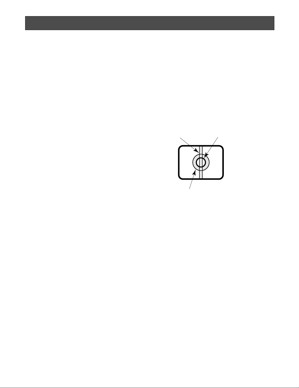
Do not aim the camera head at strong light sources.
A light source such as a spot light causes a blooming (light
bleeding) or a smear (vertical lines).
Installing place
Contact your dealer for assistance if you are unsure of an
appropriate place in your particular environment.
Make sure that the installation area is strong enough to hold
the product, such as a concrete ceiling. When the installation area is not strong enough, reinforce and strengthen it.
Avoid installing in the following locations.
• Locations where it may get wet from rain or water
splash
• Locations where a chemical agent is used such as a
swimming pool (not only outdoor)
• Locations subject to steam and oil smoke such as a
kitchen
• Locations near flammable gas or vapor
• Locations where radiation or x-ray emissions are produced
• Locations subject to strong magnetic field or radio
waves
• Locations where corrosive gas is produced
• Locations where it may be damaged by briny air such
as seashores
• Locations where the temperature is not between 0°C
and +40°C {32°F and 104°F}.
• Locations subject to vibrations (the product is not
designed for on-vehicle use.)
• Locations subject to condensation as the result of
severe changes in temperature
Smear
Blooming
Bright subject
Page 7

Be sure to remove this product if it is not in use.
Radio interference
When the product is used near TV/radio antenna, strong
electric field or magnetic field (near a motor or a transformer), images may be distorted and noise sound may be
produced.
Do not install this product in a humid or dust-laden
environment.
Otherwise, lifetime of the internal parts may be shortened.
7
Page 8

8
Preface
This system is a compact and light type HD camera control unit (hereafter called CCU) with high image quality and multiple
functions by introducing digital signal processing. The camera head is separately mounted.
• GP-US932CU, GP-US932CUE, CCU for 3CCD color camera (HDMI output connector equipped)
• GP-US932CUS, GP-US932CUSE, CCU for 3CCD color camera (SDI output connector equipped)
This unit is used in combination with the optional 3CCD HD camera head.
• GP-US932H, GP-US932HE, camera head for 3CCD color camera
• The multi-format output applicable to 1 080i, 720p, 480p (576p*) and 480i (576i*) is available.
* The value is for GP-US932CUE/GP-US932CUSE.
• Signal transmission without signal degradation has been achieved thanks to the HDMI or SDI output connectors.
• The dynamic range expansion function allows users to shoot even images with a wide range of brightness contrast and
facilitate their visibility.
These instructions explain the system that consists of this unit and the optional camera head.
T rademarks and Registered Trademarks
HDMI, the HDMI logo and High-Definition Multimedia Interface are trademarks or registered trademarks of HDMI Licensing
LLC.
Page 9
9
Major Operating Controls and Their Functions
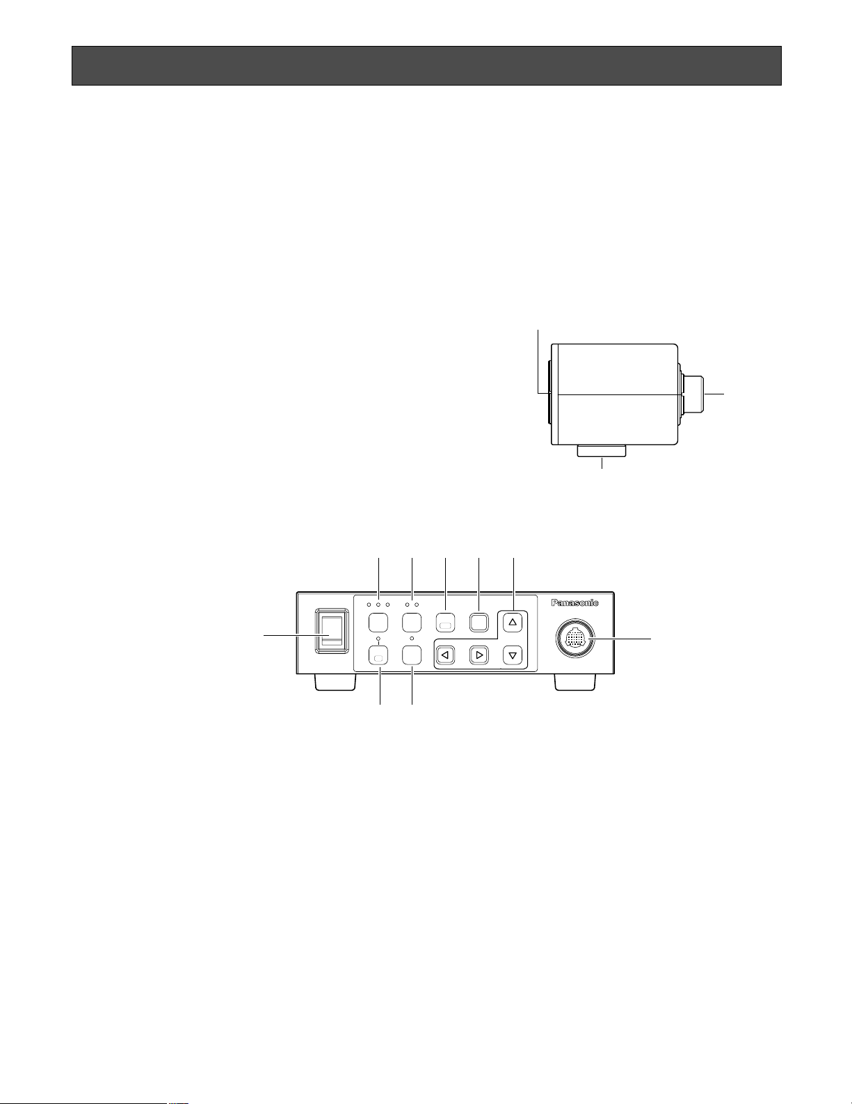
■ Camera head
q Lens mount section
C-mount lens is mounted on this section. (☞ page 14)
w Camera cable connector
This connector is used to connect the camera cable
(option).
<Camera cable> (option)
GP-CA932/4, GP-CA932/4E (4 m {13.1 ft.})
GP-CA932/6, GP-CA932/6E (6 m {19.7 ft.})
e Tripod socket
The tripod socket hole is used when the camera head is
secured to the tripod.
The tripod socket can be mounted on either top or bottom of the camera head.
Tripod socket hole: 1/4-20 UNC
Important:
• Be sure to turn off the power of the CCU before connecting or disconnecting the camera cable.
• Avoid bending excessively or breaking the camera
cable.
• Use the specific-camera head only.
w
q
e
GP–US932
CAMERA
SEL
FREEZE
LOW HIGH
DC POWER
213
SCENE
GAIN
EXPAND
D RANGE
MENU
BAR
AWC
ON
OFF
r
tyui
o
!0
!2
!1
r Power switch [DC POWER]
This switch toggles the power of the CCU and camera
head on and off. The switch lights green while the
power is turned on.
t Scene file selection button [SCENE]
The button selects a scene file from 1 to 3. Each scene
file should be set up beforehand using the SETUP
menu. (☞ page 20)
Selection of a scene file turns on the green LED of the
selected file number.
y Gain selection button [GAIN]
This button selects a gain from OFF, LOW, and HIGH.
Selection of a gain turns on the green LED of the selected gain. No LED is turned on when the gain is set to off.
Selectable gain varies depending on the setting in the
SETUP menu (☞ page 19).
When GAIN is set to "AUTO" and SENS UP is set to
"OFF": The gain is always set to "HIGH".
u Freeze/menu button [FREEZE (MENU)]
Pressing this button: Displays the current image as a
static image when "FREEZE" in the SETUP menu is
set to "ON".
■ Camera control unit (CCU)
<Front>
Page 10

10
Notes:
• Pressing a button other than the [g] and [h] buttons provides freeze cancellation.
• When the zoom in and out functions are assigned to
the [e] and [f] buttons respectively, the image
can be scaled up and down in the image freezing
state.
Refer to page 25 for function assignment to buttons.
Holding down this button (for more than 2 seconds):
Displays the SETUP menu.
i Selection button [SEL]
Pressing this button while the SETUP menu is displayed
determines the setting.
Pressing this button except while the SETUP menu is
displayed calls up the SEL menu. (☞ page 25)
o Up/down/left/right buttons
Up button [g]: This button moves the cursor upward to
change a setting item while the SETUP menu is displayed.
Down button [h]: This button moves the cursor down-
ward to change a setting item while the SETUP
menu is displayed.
Left button [e]: This button moves the cursor leftward
or selects a setting while the SETUP menu is displayed.
This button moves the cursor in the minus direction on the level adjustment scale or selects a setting item while the SEL menu is displayed.
When the zoom out function is assigned to the left
button, the image can be scaled down (☞ page
25).
Right button [f]: This button moves the cursor right-
ward or selects a setting while the SETUP menu is
displayed.
This button moves the cursor in the plus direction
on the level adjustment scale or selects a setting
item while the SEL menu is displayed.
When the zoom in function is assigned to the right
button, the image can be scaled up (up to 2.5-fold)
(☞ page 25).
!0 Color bar display/AWC button [BAR/AWC]
Pressing this button: Calls up the color bar on the
screen while an image is displayed. The color bar
becomes a blue back display while the SETUP
menu is displayed.
Holding down this button (for more than 2 seconds):
Starts up AWC while an image is displayed if
“WHITE BAL” in the SETUP menu is set to “AWC”.
Important:
• When the camera head is not connected, pressing
the [BAR/AWC] button does not activate any operation.
!1 Dynamic range button [D RANGE]
This button toggles the dynamic range between NORMAL and EXPAND. The button lights green when
"EXPAND" is selected.
“EXPAND” shall be selected when dark portions are
less viewable because too bright portions are present
in a screen. (☞ page 21)
Note: The dynamic range can also be set in the scene
file. (☞ page 20)
!2 Camera cable connector
This connector is used to connect the camera cable
(option).
Page 11

FRONT SW
(Button operation
via front face)
11
ON
HD
PROGRE.
NOT USE
FRONT SW
OFF
SD
INTER.
NOT USE
RS– 232C
DC 12V INRS– 232CS – VIDEORGB/YP b P r
1
2
3
4
OUT
VIDEO SYNC
IN
ON
1234
!4
!5
!7
@0
@1
!3
!6
!9
!8
ON
HD
PROGRE.
NOT USE
FRONT SW
ON
1234
OFF
SD
INTER.
NOT USE
RS– 232C
OUT
VIDEO SYNCSDI
IN
DC 12V INRS– 232CS – VIDEORGB/YPbPr
1
2
3
4
12
!5!4
@2
!7
!8!9
@0
@1
!6
● GP-US932CUS, GP-US932CUSE
● GP-US932CU, GP-US932CUE
<Rear>
!3 HDMI output connector [HDMI] (* only for GP-
US932CU, GP-US932CUE)
This connector is used when an HDMI-ready monitor is
connected.
!4 Video output connector [VIDEO]
This connector provides composite video signals (1.0
V[P-P], 75 ohms).
!5 Synchronizing signal output/input connector [SYNC]
When an external device is synchronized, set the synchronizing signal output/input selection switch !6 to "IN"
to provide the synchronizing signal input.
When the synchronizing signal output/input selection
switch !6 is set to "OUT", the connector provides the
synchronizing signal output conformable to the video
format of this system.
Important:
• The video format shall be the same among the synchronized devices.
!6 Synchronizing signal output/input selection switch
[OUT/IN]
This switch toggles synchronizing signals between output and input.
When the synchronizing signal output is selected, set
this switch to "OUT". When the synchronizing signal
input is selected, set this switch to "IN".
!7 Function setup switches
These switches select a video format for RGB/YPbPr
output connector, SDI output connector, and HDMI output connector.
Switch OFF ON
1
2
SD (SD signal output)
INTER.
(Interlace output)
HD (HD signal output)
PROGRE.
(Progressive output)
3
4
Video
format
Switch
21
RGB/YPb
Pr output
SDI
output
HDMI
output
OFFON1 080i
bbb
ONON720p
bbb
ONOFF480p (576p*)
b
X
b
OFFOFF480i (576i*)
bb
X
NOT USE (Not used)
RS-232C
(RS-232C control)
NOT USE (Not used)
X: No output is provided.
* The value is for GP-US932CUE/GP-US932CUSE.
Note:
• When the RS-232C port is used, set Switch 4 to
"OFF" after turning off the power.
When Switch 4 is set to "OFF", button operations on
the front face are disabled.
Page 12

@2 SDI output connector [SDI]
(* only for GP-US932CUS, GP-US932CUSE)
This connector provides HD-SDI or SD-SDI output signals.
Important:
• Please use a high quality cable compatible with
HD-SDI.
!8 12 V DC power connector [DC 12V IN]
This connector is used to connect an external DC
power supply of 12 volts (2 A or more).
Important:
• A class 2 power supply of 12 V DC (10.8 to 13.2
volts) shall be used.
Compatible connector
HR10A-7P-4S (73) manufactured by HIROSE ELECTRIC
CO., LTD. (as of October 2007)
!9 RS-232C port [RS-232C]
This port is used to perform external control. Please
contact your dealer for further information.
12
Pin number Output signal
1 GND
2 GND
3 R, Pr
4 G, Y
5 B, Pb
6 VIDEO
7 SYNC
8 GND
9 GND
@0 S-video output connector [S-VIDEO]
This connector provides the luminance signal (Y) output
and color signal (C) output with synchronizing signals.
@1 RGB/YPbPr connector [RGB/YPbPr]
This connector provides the RGB signal (red, green,
and blue) output or the YPbPr signal (luminance, color
difference B, and color difference R) output. The output
signal can be set up with use of "OUTPUT SEL" in the
SETUP menu. (☞ page 19)
Pin number Signal
1 GND
2 TXD
3 RXD
4 DSR
5 GND
6 DTR
7 CTS
8 RTS
9 GND
(D-sub 9-pin connector,
male)
(D-sub 9-pin connector,
female)
Pin arrangement of
applicable connector
1
2
(Cable side)
4
3
5 1
9 6
1 5
6 9
Page 13

The following shows how to mount the camera on the tripod (locally procured).
The tripod socket can be mounted on either top or bottom of the camera head.
<Sample of camera mounting on tripod> <Change of tripod socket position>
13
Installation/Connection
Caution:
ONLY CONNECT THIS TO 12 V DC CLASS 2 POWER SUPPLY.
Be sure to connect the grounding lead to the GND terminal.
Important:
• The tripod and CCU shall be horizontally placed.
• When the camera head is mounted on a ceiling, the camera cable (option) also plays a role of a safety wire for just in case.
Use a cable tie to attach the camera cable to the camera mounting base. The cable tie shall be made of a durable material.
• An installation area for the camera mounting base shall be strong enough to support the total weight.
<Sample of camera mounting on ceiling>
Tripod socket
Camera mounting base
(locally procured)
Attach the camera cable
to the camera mounting base.
Page 14

x Turn a C-mount lens clockwise to engage the lens with
the lens mount section.
■ How to mount lens
Important:
• Be sure to turn off the power of the CCU before mounting a lens.
• A lens whose projection length of the lens mount section is 4 mm or less shall
be used.
• The recommended lens aperture ranges from F2.2 to F16. Selection of less
than F2.2 of the lens aperture may result in image blurring.
• When a zoom lens is used, focus adjustment method varies with the lens. For
further information, refer to the operating instructions for the lens.
• When the lens is removed, be sure to put the cap on the lens mount section of
the camera head.
z Remove the lens cap from the lens mount section of the
camera head.
14
C-mount:
less than 4 mm {5/32"}
Important:
• Check to see whether the surface of the optical filter is
clean before mounting a lens. If the surface is dirty, use
a blower brush for general camera to remove dust.
Recommended lenses (as of October 2007)
Manufacturer Model Model number
FUJINON High Definition Fixed Lens HAF4.8DA-1
FUJINON High Definition Zoom Lens HA4x7.5DA-1
FUJINON 3CCD Camera Lens TF2.8DA-8
FUJINON 3CCD Camera Lens TF4DA-8
FUJINON 3CCD Camera Lens TF8DA-8
FUJINON 3CCD Camera Lens TF15DA-8
Page 15

Setup items Description Page
q CAMERA ID Specifies the camera title. Through this item, a camera title is created
with alphanumeric and symbol characters, and displayed on the
screen.
w ELC Specifies the ELC function.
e SHUTTER Specifies the electronic shutter speed.
r GAIN Adjusts the gain.
t SENS UP Specifies electronic sensitivity enhancement.
y OUTPUT SEL Specifies the output signal.
u SCENE FILE Registers the settings of details, gamma, hue, etc.
DTL MODE Specifies the details.
RED DTL Adjusts the enhancement of red edge.
GAMMA Performs gamma adjustment.
KNEE Adjusts the knee point.
BLACK STRETCH Toggles the black stretch function on and off.
D-RANGE Toggles the dynamic range between NORMAL and EXPAND.
WHITE CLIP Adjusts the white clip level.
FLARE COMP Performs flare compensation.
DNR Specifies the level of the digital noise reduction function.
MATRIX Adjusts the hue.
CHROMA GAIN Adjusts chroma gain.
TOTAL PED Adjusts the pedestal level.
i WHITE BAL Specifies white balance adjustment.
o BLACK BAL Adjusts the black balance.
!0 SYNC Specifies the synchronization type.
!1 ELECTRIC ZOOM Toggles the electronic zoom on and off.
!2 FREEZE Toggles the freeze function.
15
Setting Procedures
Performing each setting item on the SETUP menu should be completed in advance to use this unit. Perform the settings for
each item in accordance with the conditions of the camera shooting location.
Note:
• In addition to the SETUP menu, this system has a simplified menu (SEL menu) that is displayed using the [SEL] button on
the front of the CCU. Refer to page 25 for further information about the SEL menu.
■ SETUP menu
The following items can be set with use of the SETUP menu.
17
18
19
19
19
19
20
20
20
20
21
21
21
21
21
21
21
22
22
23
23
24
24
24
Page 16

v To return to the camera image screen after storing the
settings, move the cursor to "END" and press the [SEL]
button.
The settings can be stored even if the power of the
CCU is turned off.
■ Basic operations
The description below explains how to operate the SETUP
menu basically.
First of all, the explanation provides how to display the
SETUP menu on the connected monitor used for adjustment.
Important:
• The following functions are not available when the camera head is not connected.
• Startup of white balance AWC
• MATRIX
• ELECTRIC ZOOM
• FREEZE
z Hold down the [FREEZE (MENU)] button for approx. 2
seconds.
→ The top screen of the SETUP menu appears.
x The SETUP menu consists of 2 pages.
To change the page, move the cursor to "P1" or "P2"
and press the [e] or [f] button.
Note:
• The cursor is a blinking part.
c Perform the settings for each item.
• Selection of setting item:
Press the [g] button or the [h] button to move the
cursor.
• Change of settings:
Press the [e] button or the [f] button.
• Display of advanced setup screen:
Press the [SEL] button when "*" is attached to the
target setting item.
• Return to previous setup screen:
Move the cursor to "RET" and press the [SEL] button.
16
Top screen of SETUP menu
** SET UP ** P1
CAMERA ID *OFF
ELC *OFF
SHUTTER OFF
GAIN OFF
SENS UP OFF
OUTPUT SEL RGB(NOR)
END
** SET UP ** P2
SCENE FILE *FILE1
WHITE BAL AWC
BLACK BAL *MANU
SYNC INT
ELECTRIC ZOOM ON
FREEZE ON
END
Page 17

1. Camera title setting [CAMERA ID]
This item specifies the camera title. The camera title that
indicates the camera location and other information about
the camera is created with alphanumeric, symbol, and
katakana characters and displayed on the screen. The
camera title is named with up to 16 characters.
Follow the procedure below to specify the camera title.
z Set "CAMERA ID" to "ON" and press the [SEL] button.
→ The title creation screen appears.
Note:
• Even if "CAMERA ID" is set to "OFF", pressing the [SEL]
button calls up the title creation screen.
Important:
• When "CAMERA ID" is set to "OFF", the camera title
does not appear even if the title is specified.
x Move the cursor to the target item with use of the [g],
[h], [e], and [f] buttons and press the [SEL] button.
→ The entered characters are displayed in the entry
range.
17
Top screen of SETUP menu
Title creation screen
Display positioning screen
<Character entry>
• To revise the character, move the cursor to "←" or "→"
and press the [SEL] button.
Move the cursor to the character to be revised in the
entry range and enter a character newly.
• To enter a blank, move the cursor to "SPACE" and press
the [SEL] button.
• To delete all the entered characters, move the cursor to
"RESET" and press the [SEL] button.
c Move the cursor to "POSI" and press the [SEL] button
after title entry.
→ The display positioning screen appears to show the
entered camera title blinking.
v Position the title with use of the [g], [h], [e], and [f]
buttons and hold down the [MENU] button for more
than 2 seconds.
→ The title position is decided and the title creation
screen appears again.
** SET UP ** P1
CAMERA ID *OFF
ELC *OFF
SHUTTER OFF
GAIN OFF
SENS UP OFF
OUTPUT SEL RGB(NOR)
END
ABCDEFGHIJKLM
NOPQRSTUVWXYZ
0123456789
().,'":;&#!?=
+-*/%$ДЬЦЖСА
← →
*POSI RET END RESET
................
SPACE
Editing area
FLOOR 1
Page 18

MANU: The detection area can be manually specified.
(☞ page 18)
AUTO: The dark areas are automatically covered and
only the bright areas are automatically detected.
c Move the cursor to "PEAK/AVE" and use the [e] and
[f] buttons to adjust the detection level.
When the cursor is moved to "P", the peak value (maximum) is detected. When the cursor is moved to "A", the
average value is detected.
Manual setup of detection area
The detection area is manually specified.
z Select "MANU" for "AREA" on the "ELC CONT" screen
and press the [SEL] button.
→ The mask setting screen appears.
x Use the [g], [h], [e], and [f] buttons to select an
area to be masked and press the [SEL] button.
→ The selected area is displayed white.
Note:
• To cancel the specified area, move the cursor to the
target area and press the [SEL] button.
To cancel all the masks, hold down the [e] and [f]
buttons simultaneously for more than 2 seconds.
c Hold down the [MENU] button for more than 2 seconds
after area setting.
→ The "ELC CONT" screen appears again.
18
2. ELC setting [ELC]
Setting ELC (electronic light control) to ON provides automatic adjustment of the screen brightness. The convergence level of ELC can be specified at “BRIGHTNESS” in
the SEL menu (☞ page 25).
If a photographic subject has a bright light such as a spotlight in its backgroud, the subject may appear shadowy. To
eliminate this phenomenon, mask the bright area in the
background to perform correction.
z Set "ELC" to "ON" and press the [SEL] button.
→ The "ELC CONT" screen appears.
x Move the cursor to "AREA" and use the [e] and [f]
buttons to select an area.
The area is selectable from the types shown below.
→ The detection areas shown as follows are not dis-
played.
ALL (default): All of the areas on
the screen are the detection
area.
S CIRCLE: The small circle in the
center of the screen is the
detection area.
M CIRCLE: The medium circle in
the center of the screen is
the detection area.
L CIRCLE: The large circle in the
center of the screen is the
detection area.
Top screen of SETUP menu
"ELC CONT" screen
"ELC CONT" screen
Mask setting screen
** SET UP ** P1
CAMERA ID *OFF
ELC *OFF
SHUTTER OFF
GAIN OFF
SENS UP OFF
OUTPUT SEL RGB(NOR)
END
** ELC CONT **
AREA ALL
....A
....
PEAK/AVE P
|
** ELC CONT **
AREA ALL
PEAK/AVE P
RET END
....|....A
RET END
Page 19

19
3. Electronic shutter setting [SHUTTER]
The electronic shutter speed is specified. The speed is
selectable from the following.
OFF (default),1/100 (1/120*), 1/250, 1/500, 1/1000,
1/2000, 1/4000, 1/10000, and MANU
Select "MANU", and press [SEL] button. The "SHUTTER"
screen appears to adjust the shutter speed in detail.
Adjustable speed range: 3/562 (2/562*) – 552/562
* The value is for GP-US932CUE/GP-US932CUSE.
Note:
• When the shutter speed is specified, be sure to set both
"ELC" and "SENS UP" to "OFF". (☞ pages 18 and 19)
4. Gain adjustment [GAIN]
The gain adjustment is selectable from the following.
OFF (default): The gain is not adjusted.
AUTO (L), AUTO (H): The gain is automatically adjusted.
MANU (L), MANU (H): The gain is manually adjusted.
The gain level is adjusted in detail.
The gain can be finely adjusted in the "LOW" and "HIGH"
levels.
z Select an adjustment in "GAIN" and press the [SEL] but-
ton.
→ The "GAIN LEVEL" screen appears.
x Move the cursor to "HIGH" or "LOW" and adjust the level
with use of the [e] or [f] button.
"SHUTTER" screen
"GAIN LEVEL" screen
Important:
• The "LOW" level cannot be larger than the "HIGH" level.
• When "SENS UP" is set to "OFF" or "---", "AUTO (L)" is not
available.
5. Electronic sensitivity enhancement
setting [SENS UP]
The magnification of the electronic sensitivity is selectable
from the following.
OFF (default), AUTO (x2), AUTO (x4), AUTO (x8), MANU
(x2), MANU (x4), and MANU (x8)
Notes:
• When "MANU (x2)", "MANU (x4)", or "MANU (x8)" is
selected, be sure to set "ELC" to "OFF". (☞ page 18)
• When "GAIN" is set to "OFF" or to a low level, video may
become grainy and unstable. In such a case, adjust the
electronic sensitivity.
• When "SHUTTER" is set to other than "OFF", "---"
appears and electronic sensitivity enhancement function is not available.
• When the electronic sensitivity enhancement function is
used, time for CCD readout is elongated to enhance the
sensitivity. Therefore, the residual image of a moving
subject is increased in accordance with the magnification of the sensitivity.
6. Output signal setting [OUTPUT SEL]
The output signals of RGB/YPbPr output connector, HDMI
output connector are specified.
Output signals vary with models.
GP-US932CU, GP-US932CUE (HDMI output connector
equipped): RGB (NOR) (default), RGB (ENH), YPbPr
(422), YPbPr (444)*
* The output signal of the RGB/YPbPr output connector is
the same in both RGB (NOR) and RGB (ENH) and in
both YPbPr (422) and YPbPr (444), respectively.
GP-US932CUS, GP-US932CUSE (SDI output connector
equipped): RGB (default), YPbPr
** SHUTTER **
MANU SET 552/562
RET END
** GAIN LEVEL **
LOW –
HIGH –
RET END
...|.....
........
+
|+
Page 20

z Move the cursor to "DTL MODE" on the "SCENE FILE"
screen and press the [SEL] button.
→ The "DTL MODE" screen appears.
x Move the cursor to “PATTERN”, select a pattern from
among “1”, “2” and “3”, and press the [SEL] button.
→ The settings of “DTL BAND” and “DTL LEVEL” are
applied to “USER”.
The band and level can be manually adjusted in
“USER”. Perform adjustment on an as-needed basis.
Be sure to view the monitor when the adjustment is performed.
Note:
• The band and level can also be adjusted directly without applying any of the patterns, “1”, “2”, and “3” to
“USER”.
c Move the cursor to "DTL BAND" and adjust the band
with use of the [e] or [f] button.
When the level indicator moves in the "+" direction, the
edge becomes thinner (band becomes higher). When
the level indicator moves in the "–" direction, the edge
becomes thicker (band becomes lower).
v Move the cursor to "DTL LEVEL" and adjust the level
with use of the [e] or [f] button.
When the level indicator moves in the "+" direction, the
image becomes sharper. When the level indicator
moves in the "–" direction, the image becomes softer.
Note:
• Jaggies may appear on the edge of a photographic
subject, but this phenomenon is not abnormal. If this
phenomenon is not favorable, decrease “DTL BAND” or
“DTL LEVEL” to adjust the image quality.
[RED DTL] Adjusts the enhancement of red
edge.
The red edge enhancement level of images through the
camera is adjusted.
The enhancement level is selectable from the following.
OFF (default): No edge enhancement is performed on the
red portion.
LOW: The low level of edge enhancement is performed on
the red portion.
HIGH: The high level of edge enhancement is performed on
the red portion.
[GAMMA] Performs gamma adjustment.
Be sure to view a waveform monitor or a color video monitor
when the gamma adjustment is performed.
Move the cursor to "GAMMA" and adjust the gamma level
with use of the [e] or [f] button.
When the level indicator moves in the "+" direction, the correction level becomes larger. When the level indicator
moves in the "–" direction, the correction level becomes
smaller.
Moving the cursor to the far end of the “+” direction sets the
gamma correction to OFF.
20
7. Scene file setting [SCENE FILE]
Registration of details, gamma, hue, etc. as a scene file in
accordance with an installation location allows users to
employ the registered contents only by pressing the
[SCENE] button on the front face of the CCU.
Up to 3 scene files can be registered.
Scene file registration is performed on the "SCENE FILE"
screen. When a scene file to be registered on the top
screen, "SCENE FILE", in the SETU P menu is selected and
the [SEL] button is pressed, the "SCENE FILE" screen
appears. The "SCENE FILE" screen consists of 2 pages.
The selected scene file number appears beside the screen
title.
[DTL MODE] Specifies the details.
The band and level of the edge correction are specified.
"SCENE FILE" screen
"DTL MODE" screen
Scene file number
** SCENE FILE 1 ** P1
DTL MODE *MANU
RED DTL OFF
GAMMA –
KNEE *MANU
BLACK STRETCH OFF
D-RANGE NORMAL
WHITE CLIP –
RET END
....
....
|
|
....
....
+
+
** SCENE FILE 1 ** P2
FLARE COMP OFF
DNR LOW
MATRIX *USER
CHROMA GAIN –
TOTAL PED –
RET END
.....|...
....
....
|
+
+
** SCENE FILE 1 ** P1
DTL MODE *MANU
RED DTL OFF
GAMMA –
KNEE *MANU
BLACK STRETCH OFF
D-RANGE NORMAL
WHITE CLIP –
RET END
....
....
|
|
....
....
+
+
** DTL MODE **
PATTERN USER
DTL BAND —
DTL LEVEL —
RET END
. . . .
....
|
....
|
+
+
Page 21

21
Important:
• In the case of the following, "---" appears and gamma
adjustment is not available.
• When "BLACK STRETCH" is set to "ON"
• When "D-RANGE" is set to "EXPAND"
[KNEE] Adjusts the knee point.
Be sure to view a waveform monitor or a color video monitor
when the knee point adjustment is performed.
The knee point adjustment is selectable from the following.
MANU (default): The knee point is manually adjusted.
AUTO: The knee point is automatically adjusted.
When "MANU" is selected, follow the steps below to adjust
the knee point.
z Select "MANU" and press the [SEL] button.
→ The "KNEE MANU" screen appears.
x Adjust the knee point with use of the [e] or [f] button.
Important:
• When "D-RANGE" is set to "EXPAND", the knee point
adjustment is disabled.
[BLACK STRETCH] Toggles the black stretch
function on and off.
Selection "ON" or "OFF" (default) determines whether or not
to perform the black stretch function.
When "ON" is selected, black crushing is corrected at low
illuminance to make an image more viewable.
Important:
• When "D-RANGE" is set to "EXPAND", the black stretch
setting is disabled.
[D-RANGE] Toggles the dynamic range
between NORMAL and EXPAND.
The dynamic range is set to "NORMAL" (default) or
"EXPAND".
Selection of “EXPAND” makes high contrast images more
viewable.
[WHITE CLIP] Adjusts the white clip level.
Be sure to view a waveform monitor or a color video monitor
when the white clip level is adjusted with use of the [e] or
[f] button.
When the level indicator moves in the "+" direction, the level
becomes higher. When the level indicator moves in the "–"
direction, the level becomes lower.
Important:
• When "D-RANGE" is set to "EXPAND", the white clip
adjustment is disabled.
[FLARE COMP] Performs flare compensation.
Selection "ON" or "OFF" (default) determines whether or not
to perform the flare compensation.
When "ON" is selected, flare is reduced.
[DNR] Specifies the level of the digital noise
reduction function.
The digital noise reduction function reduces noise. The
effect level is selectable from the following.
LOW (default): The low level of digital noise reduction is
performed. (smaller residual image)
HIGH: The high level of digital noise reduction is per-
formed. (larger residual image)
OFF: The digital noise reduction function is disabled.
[MATRIX] Adjusts the hue.
Be sure to view a vector scope or a color video monitor
when the hue adjustment is performed.
z Display your target color in the screen center as large
as possible.
x Select the axis close to your target color using
"MATRIX" on the "SCENE FILE" screen. The axis is
selectable from the following.
"KNEE MANU" screen
"SCENE FILE" screen
"MATRIX" screen
** KNEE MANU **
KNEE POINT –
RET END
........
|
+
** SCENE FILE 1 ** P2
FLARE COMP OFF
DNR LOW
MATRIX *USER
CHROMA GAIN –
TOTAL PED –
RET END
.....|...
....
....
|
+
+
** MATRIX ** USER
....
....
....
|
....
|
+
+
B PHASE —
B GAIN —
USER AREA *
RET END
Page 22

Note:
• Every time the [SEL] button is pressed, the size of the
rectangle cursor changes in the order of large → medi-
um → small.
Select a size to meet the photographic subject size.
x Hold down the [MENU] button for more than 2 seconds.
→ The "MATRIX" screen appears again.
c To perform fine tuning, adjust "GAIN" (chroma) and
"PHASE" (hue).
For example, the adjustment of "PHASE" or "GAIN" of
"R/R-Ye" on the following screen provides the simultaneous adjustment of "PHASE" or "GAIN" of the adjacent
axes "R" and "R-Ye" in "Color matrix splitting chart".
Note:
• When the color on the axis in the color matrix splitting
chart is detected, the adjacent axes are not displayed.
[CHROMA GAIN] Adjusts chroma gain.
Be sure to view a vector scope or a color video monitor
when the chroma gain is adjusted with use of the [e] or
[f] button.
When the level indicator moves in the "+" direction, the
chroma level becomes higher. When the level indicator
moves in the "–" direction, the chroma level becomes lower.
[TOTAL PED] Adjusts the pedestal level.
Be sure to view a waveform monitor or a color video monitor
when the pedestal level is adjusted with use of the [e] or
[f] button.
When the level indicator moves in the "+" direction, the
image becomes brighter. When the level indicator moves in
the "–" direction, the image becomes darker.
22
USER (default),B-Mg, Mg, Mg-R, R, R-Ye, Ye, Ye-G, G,
G-Cy, Cy, Cy-B, and B
c Press the [SEL] button after axis selection.
→ The "MATRIX" screen appears.
v To perform fine tuning, use the [e] or [f] button to
adjust "GAIN" (chroma) and "PHASE" (hue).
When the color axis is unclear
When "USER AREA" is selected on the "MATRIX" screen,
the axis is automatically displayed by selecting a color on
the screen.
Color selection is performed on the color detection screen.
The white rectangle cursor is blinking to select a target
color on the color detection screen.
<Color matrix splitting chart>
* This chart is a guideline for displaying the closest axis
at adjustment.
z Point the camera at the center of the photographic sub-
ject with which the color is detected.
If the camera is immovable, move the rectangle cursor
to the area with a target color with use of the [g], [h],
[e], and [f] buttons.
Color detection screen
R-Ye
Cursor
(Blinking)
Mg-R
R
R-Ye
Ye
Ye-G
G
G-Cy
Mg
B-Mg
B
Cy-B
Cy
** MATRIX ** USER
....
....
R/R-Ye PHASE –
R PHASE –
R-Ye PHASE –
R/R-Ye GAIN –
R GAIN –
R-Ye GAIN –
USER AREA *
RET END
....
....
....
....
....
|
....
|
....
|
....
|
....
|
....
|
+
+
+
+
+
+
Page 23

23
8. White balance setting [WHITE BAL]
The white balance adjustment is selectable from the following.
AWC (default): The automatic white balance control mode
is activated. This adjustment is suitable for a location
where a light source is stable.
When "AWC" is selected, the operation to adjust the
white balance is required.
ATW: Activates the automatic white balance tracking mode.
The camera continuously measures the white balance
and automatically performs adjustment.
If the situation meets one of the following or other, color
may not be accurately reproduced. In such a case,
select "AWC" to adjust the white balance.
• The photographic subject is mostly highly-colored.
• The photographic atmosphere is under the bright
blue sky or at nightfall.
• The illumination of the light illuminating the photographic subject is low.
MANU: The white balance is manually adjusted.
When "AWC" is selected, follow the steps below to adjust
the white balance.
z Point the camera at a white photographic subject.
x Hold down the [BAR (AWC)] button for more than 2
seconds on the front face of the CCU.
→ AWC starts up and the LED located above the
[BAR (AWC)] button blinks. When “AWC OK”
appears and the LED goes out, the adjustment is
completed.
Note:
• “AWC NG” appears. Perform the steps 1 and 2 again if
“AWC NG” appears and the LED stays on.
When "MANU" is selected, follow the steps below to adjust
the white balance.
z Select "MANU" and press the [SEL] button.
→ The "WHITE BAL" screen appears.
x Move the cursor to "R-GAIN" or "B-GAIN" and adjust the
white balance with use of the [e] or [f] button.
9. Black balance setting [BLACK BAL]
The black balance adjustment is generally unnecessary,
but the adjustment is available also by hand.
z Move the cursor to "BLACK BAL" and press the [SEL]
button.
→ The "BLACK BAL" screen appears.
x Mount the lens cap on the camera lens.
c Move the cursor to "R-PED", be sure to view a vector
scope or a waveform monitor when "R-PED" is adjusted
with use of the [e] or [f] button. Adjustment shall be
performed so that the carrier is minimized.
v Move the cursor to "B-PED" and adjust "B-PED" with use
of the [e] or [f] button while viewing a vector scope or
a waveform monitor. Adjustment shall be performed so
that the carrier is minimized.
"WHITE BAL" screen
Top screen of SETUP menu
"BLACK BAL" screen
** SET UP ** P2
SCENE FILE *FILE1
WHITE BAL AWC
BLACK BAL *MANU
SYNC INT
ELECTRIC ZOOM ON
FREEZE ON
END
** BLACK BAL **
....
....
....
|
....
|
+
+
R-PED –
B-PED –
RET END
** WHITE BAL **
....
....
....
|
|
....
+
+
R-GAIN –
B-GAIN –
RET END
Page 24

24
10. Synchronization setting [SYNC]
The synchronization state is displayed. The horizontal
phase in the external synchronization can also be adjusted.
The internal synchronization is indicated as "INT", and the
external synchronization is indicated as "EXT".
The horizontal phase in the external synchronization is adjusted.
z Set the synchronizing signal input/output selection
switch on the rear face of the CCU to "IN".
x Connect the video synchronizing signal to the synchro-
nizing signal output/input connector.
c Perform the settings of the function setup switches 1
and 2 in accordance with the video format used by the
device to be synchronized. (☞ page 11)
v Move the cursor to "SYNC" on the top screen of the
SETUP menu.
b Press the [SEL] button after making sure that "EXT"
appears.
→ The "SYNC" screen appears.
n Connect the Y or G signal from the RGB/YPbPr output
connector and the video synchronizing input signal to
an oscilloscope, observe the horizontal synchronization
component.
m Adjust the horizontal phase with use of the [e] or [f]
button.
Top screen of SETUP menu
"SYNC" screen
1 1. Electronic zoom setting [ELECTRIC
ZOOM]
Selection "ON" (default) or "OFF" determines whether or not
to use the electronic zoom.
To prevent the electronic zoom from being active by mistake, select "OFF".
When "ON" is selected, assignment of the zoom function to
the [e] and [f] buttons in the SEL menu allows users to
scale up (up to 2.5 times) or scale down a photographic
subject with use of the [e] or [f] button.
Notes:
• Calling up the SETUP menu cancels scale up and
down.
• When "ELECTRIC ZOOM" is set to "OFF", "ZOOM OFF"
appears in the SEL menu, and the zoom function is not
adjustable.
12. Image freezing [FREEZE]
Selection "ON" (default) or "OFF" determines whether or not
to enable the freeze function.
When "ON" is selected, pressing the [FREEZE (MENU)] button on the front face of the CCU allows users to display the
video currently displayed as a static image. (☞ page 9)
■ Default setting restoring
• When the settings of the level indicators (–....I....+) in
the SETUP menu or SEL menu are reset to the default,
hold down both of the [e] and [f] buttons simultaneously for more than 2 seconds.
• When all the settings in the SETUP and SEL menu are
reset to the default, move the cursor to "END" on the
bottom line, and hold down both of the [FREEZE
(MENU)] and [h] buttons simultaneously for more than
2 seconds.
** SET UP ** P2
SCENE FILE *FILE1
WHITE BAL AWC
BLACK BAL *MANU
SYNC INT
ELECTRIC ZOOM OFF
FREEZE OFF
END
** SYNC **
....
....
H PHASE —
RET END
|
+
Page 25

The SEL menu is a simplified menu that can be called up
by pressing the [SEL] button while an image is displayed.
The following items can be set with use of the SEL menu.
• Image level [BRIGHTNESS]: Adjusts the brightness
(ELC, gain (AUTO), and the convergence level of electronic sensitivity enhancement (AUTO)).
• Red level [R-GAIN]: Adjusts the red level.
• Blue level [B-GAIN]: Adjusts the blue level.
• Edge enhancement level [DTL-LEVEL]: Adjusts the
edge enhancement level.
• Electronic zoom [ZOOM]: Adjusts the zoom factor.
• Detection area [AREA]: Specifies the detection areas of
ELC, gain (AUTO), and electronic sensitivity enhancement (AUTO).
■ How to display or operate the SEL
menu
z Press the [SEL] button.
→ The SEL menu appears.
x Press the [SEL] button to call up the screen of the item
to be changed.
c Use of the [e] or [f] button allows users to adjust the
setting.
Notes:
• Pressing the [SEL] button displays the last displayed
item while the power is supplied.
• No operation for more than 3 seconds also terminates
the SEL menu.
25
SEL Menu
■ Button assignment
Only pressing the [e] or [f] button allows users to assign
the settings in the SEL menu while an image is displayed.
How to assign settings
z Call up the screen of the setting to be assigned in the
SEL menu to a button.
x Hold down both of the [SEL] and [FREEZE (MENU)]
buttons simultaneously while the screen is displayed
until the displayed contents disappear.
c Use the [e] or [f] button to display and assign the
settings to be stored.
Note:
• If "ZOOM" is assigned to a button, zoom can be adjusted in the image freezing state (☞ page 24).
Page 26

Troubleshooting
Before asking for repairs, check the symptoms with the following table.
Contact your dealer if a problem cannot be solved even after checking and trying the solution in the table or a problem is not
described below.
Symptom Cause/solution
No image displayed
Camera with no response to
the button operation on the
front face of the CCU
The lighting LED of the
[SCENE] button unchanged
• Are the cables appropriately connected to the video output
connector, S-VIDEO output connector, RGB/YPbPr output
connector, HDMI output connector, or SDI output connector, respectively?
Check whether each cable is appropriately connected.
• Is the monitor luminance appropriately adjusted, or is the
contrast appropriately adjusted?
Check whether the monitor settings are appropriate.
• Is the function setup switch No. 4 set to "ON"?
Set the function setup switch No. 4 to "ON".
• Pressing once displays the state.
Press the [SCENE] button repeatedly until your target LED
lights.
Reference
pages
11, 12
—
11
9
26
The lighting LED of the [GAIN]
button unchanged
Only the color bar displayed
The hue [MATRIX] unadjustable in the menu
• Pressing once displays the state.
Press the [GAIN] button repeatedly until your target LED
lights.
• Is the camera cable appropriately connected at both the
connector of the CCU and the connector of the camera
head?
Check whether the connection is appropriately established.
• Is the camera cable appropriately connected at both the
connector of the CCU and the connector of the camera
head?
Connection between the camera head and camera cable is
required to adjust the image quality.
Check whether the connection is appropriately established.
9
9
9
Page 27

• Try to change the setting of "DTL MODE".
27
20
• Is the lens aperture appropriately adjusted?
Check whether the aperture is appropriately adjusted.
Use lenses with recommended F number or higher and
3CCD-specific lenses.
Symptom
Blurred screen
Plural edges visible
"AWC OK" not displayed
Black bars at right and left of
image
Vertically longer image
No sound from monitor
• When the screen is too bright, narrow the lens aperture or
set "ELC" to "ON".
• This phenomenon depends on the specifications of the
monitor.
Select the wide and full screen display at the monitor side.
• This unit provides outputs on the assumption that the screen
is 16:9.
Select the wide screen display at the monitor side.
• The monitor is not applicable to sound output.
—
Cause/solution
Reference
pages
14
• Try to change the monitor cable.
—
14, 18
—
—
Page 28

28
● GP-US932CU/GP-US932CUS
Power source: 12 V DC
Power consumption: 15 W (excluding camera head)
Pick-up system: Micro prism system
Image sensor: 1/3" 3CCD, interline transfer (IT) equipped (progressive scanning supported)
Synchronization: Internal or external synchronization
Video output: Video output: BNC Connector x1, 1.0 V[P-P]/75 Ω
S-video output: S-video connector x1
Y: 0.714 V[P-P]/75 Ω
C: 0.286 V[P-P]/75 Ω
RGB/YPbPr output: D-sub 9-pin connector x1
R, G, B: 0.7 V[P-P]/75 Ω
Y: 0.7 V[P-P]/75 Ω
Pb, Pr: 0.525 V[P-P]/75 Ω
SYNC: 0.6 V[P-P]/75 Ω (at output using 1 080i or 720p)
0.3 V[P-P]/75 Ω (at output using 480p or 480i)
VIDEO: 1.0 V[P-P]/75 Ω
HDMI output: HDMI connector x1 (GP-US932CU only)
SDI output: BNC connector x2 (GP-US932CUS only)
Video format: Video output: 480/59.94i
S-video output: 480/59.94i
RGB/YPbPr output: 1 080/59.94i, 720/59.94p, 480/59.94p, 480/59.94i
HDMI output: 1 080/59.94i, 720/59.94p, 480/59.94p (GP-US932CU only)
SDI output: 1 080/59.94i, 720/59.94p, 480/59.94i (GP-US932CUS only)
Required Illumination: 2 000 lx (3 200 K, F5.6)
Minimum illumination: 40 lx {0.4 footcandle} (F2.8, GAIN: HIGH, 30 % output, at center)
Signal-to-noise ratio: 54 dB (at output using 1 080i)
Horizontal resolution: 700 TV lines at center (when 1 080i output)
Color bar: SMPTE color bar with 0 % set-up
Functions: Camera title, ELC, electronic shutter, gain adjustment, electronic sensitivity enhancement,
output signal, scene file, white balance, black balance, synchronization, electronic zoom,
image freezing
External control: RS-232C D-sub 9-pin connector x1
Ambient operating temperature: 0 °C to 40 °C {32 °F to 104 °F}
Ambient operating humidity: 30 % to 90 %
Dimensions: GP-US932CU, GP-US932CUS: 170 (W) x 44 (H) x 229 (D) mm {6-11/16"(W) x 1-3/4"(H) x 9-
1/16"(D)} (excluding rubber feet and protruding portions)
GP-US932H: 37 (W) x 47 (H) x 60 (D) mm {1-7/16"(W) x 1-7/8"(H) x 2-3/8"(D)} (excluding tripod socket and protruding portions)
Weight: GP-US932CU: 1.3 kg {2.9 lbs}
GP-US932CUS: 1.45 kg {3.2 lbs}
GP-US932H: 150 g {0.3 lbs}
Finish: Ivory color coating
Dimensions and Weights indicated are approximate.
Specifications are subject to change without notice.
Specifications
Page 29

29
● GP-US932CUE/GP-US932CUSE
Power source: 12 V DC
Power consumption: 15 W (excluding camera head)
Pick-up system: Micro prism system
Image sensor: 1/3" 3CCD, interline transfer (IT) equipped (progressive scanning supported)
Synchronization: Internal or external synchronization
Video output: Video output: BNC Connector x1, 1.0 V[P-P]/75 Ω
S-video output: S-video connector x1
Y: 0.7 V[P-P]/75 Ω
C: 0.3 V[P-P]/75 Ω
RGB/YPbPr output: D-sub 9-pin connector x1
R, G, B: 0.7 V[P-P]/75 Ω
Y: 0.7 V[P-P]/75 Ω
Pb, Pr: 0.525 V[P-P]/75 Ω
SYNC: 0.6 V[P-P]/75 Ω (at output using 1 080i or 720p)
0.3 V[P-P]/75 Ω (at output using 576p or 576i)
VIDEO: 1.0 V[P-P]/75 Ω
HDMI output: HDMI connector x1 (GP-US932CUE only)
SDI output: BNC connector x2 (GP-US932CUSE only)
Video format: Video output: 576/50i
S-video output: 576/50i
RGB/YPbPr output: 1 080/50i, 720/50p, 576/50p, 576/50i
HDMI output: 1 080/50i, 720/50p, 576/50p (GP-US932CUE only)
SDI output: 1 080/50i, 720/50p, 576/50i (GP-US932CUSE only)
Required Illumination: 2 000 lx (3 200 K, F5.6)
Minimum illumination: 40 lx {0.4 footcandle} (F2.8, GAIN: HIGH, 30 % output, at center)
Signal-to-noise ratio: 54 dB (at output using 1 080i)
Horizontal resolution: 700 TV lines at center (when 1 080i output)
Color bar: EUB color bar with 0 % set-up
Functions: Camera title, ELC, electronic shutter, gain adjustment, electronic sensitivity enhancement,
output signal, scene file, white balance, black balance, synchronization, electronic zoom,
image freezing
External control: RS-232C D-sub 9-pin connector x1
Ambient operating temperature: 0 °C to 40 °C {32 °F to 104 °F}
Ambient operating humidity: 30 % to 90 %
Dimensions: GP-US932CUE, GP-US932CUSE: 170 (W) x 44 (H) x 229 (D) mm {6-11/16"(W) x 1-3/4"(H) x
9-1/16"(D)} (excluding rubber feet and protruding portions)
GP-US932HE: 37 (W) x 47 (H) x 60 (D) mm {1-7/16"(W) x 1-7/8"(H) x 2-3/8"(D)} (excluding
tripod socket and protruding portions)
Weight: GP-US932CUE: 1.3 kg {2.9 lbs}
GP-US932CUSE: 1.45 kg {3.2 lbs}
GP-US932HE: 150 g {0.3 lbs}
Finish: Ivory color coating
Dimensions and Weights indicated are approximate.
Specifications are subject to change without notice.
Page 30

30
● GP-US932CU/GP-US932CUS
Operating Instructions (This document) .............................................................. 1 pc.
Warranty Card for U.S. Field ................................................................................ 1 pc.
● GP-US932CUE/GP-US932CUSE
Operating Instructions (This document) .............................................................. 1 pc.
Standard Accessories
● GP-US932CU/GP-US932CUS
3CCD Color Camera Head GP-US932H
3CCD Color Camera Cable GP-CA932/4
3CCD Color Camera Cable GP-CA932/6
● GP-US932CUE/GP-US932CUSE
3CCD Color Camera Head GP-US932HE
3CCD Color Camera Cable GP-CA932/4E
3CCD Color Camera Cable GP-CA932/6E
Optional Accessories
Page 31

31
Page 32

For U.S., Canadian and Puerto Rican fields:
Panasonic System Solutions Company,
Unit Company of Panasonic Corporation of North America
www.panasonic.com/business/
For customer support, call 1.800.528.6747
Three Panasonic Way 2H-2, Secaucus, New Jersey 07094
Panasonic Canada Inc.
5770 Ambler Drive,Mississauga,
Ontario, L4W 2T3 Canada (905)624-5010
http://www.panasonic.ca
Panasonic Sales Company
Division of Panasonic Puerto Rico Inc.
San Gabriel Industrial Park 65th Infantry Ave. KM. 9.5 Carolina
P.R. 00985(809)750-4300
© 2007 Matsushita Electric Industrial Co., Ltd. All Rights Reserved. NM1107-1117 3TR005380BAA Printed in Japan
For European and other fields:
Matsushita Electric Industrial Co., Ltd.
Osaka, Japan
http://panasonic.net
Importer's name and address to follow EU rules:
Panasonic Testing Centre
Panasonic Services Europe GmbH
Winsbergring 15, 22525 Hamburg F.R.Germany
Information on Disposal for Users of Waste Electrical & Electronic Equipment (private households)
This symbol on the products and/or accompanying documents means that used electrical and electronic products should not be
mixed with general household waste.
For proper treatment, recovery and recycling, please take these products to designated collection points, where they will be
accepted on a free of charge basis. Alternatively, in some countries you may be able to return your products to your local retailer
upon the purchase of an equivalent new product.
Disposing of this product correctly will help to save valuable resources and prevent any potential negative effects on human
health and the environment which could otherwise arise from inappropriate waste handling. Please contact your local authority
for further details of your nearest designated collection point.
Penalties may be applicable for incorrect disposal of this waste, in accordance with national legislation.
For business users in the European Union
If you wish to discard electrical and electronic equipment, please contact your dealer or supplier for further information.
Information on Disposal in other Countries outside the European Union
This symbol is only valid in the European Union.
If you wish to discard this product, please contact your local authorities or dealer and ask for the correct method of disposal.
 Loading...