

Page 1
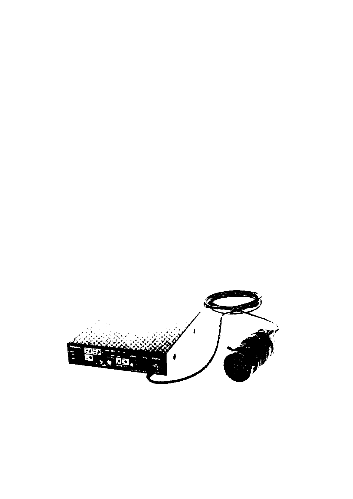
Operating
Instructions
3 CCD Coioi- Camera Head
GP-US522H
GP-US532H
3 CCD Color Camera CCU
GP-US522CU
i fto?.
Panasonic
ic r.or-r-ac.f or ope!a;w Ihii viyuti.’.. \i c-aco -cod theis compl«ieV
Page 2
CONTENTS
PREFACE .............................................................................................
FEATURES ...........................................................................................
PRECAUTIONS ....................................................................................
MAJOR OPERATING CONTROLS AND THEIR FUNCTIONS
Camera Head
Camera Control Unit
CONNECTIONS ..................................................
SETUP
1. CAMERA SETUP MENU
2. SETUP OPERATION
SETTING PROCEDURES
PREVENTION OF BLOOMING AND SMEAR .................................................................................................................................................................19
SPECIFICATIONS ............................................................................................................................................................................................................20
OPTIONAL ACCESSORIES ...........................................................................................................................................................................................21
...................................................
........................................
................................................................
............................
..................................
..................................
1
1
2
3
3
3
7
9
9
9
11
CAUTION:
Before attempting to connect or operate this product,
please read the label on the bottom.
CAUTION
RISK OF ELECTRIC SHOCK
A
CAUTION:
TO REDUCE THE RISK OF ELECTRIC SHOCK, DO
NOT REMOVE COVER (OR BACK). NO USER SER
VICEABLE PARTS INSIDE.
REFER SERVICING TO QUALIFIED SERVICE PER
SONNEL
DO NOT OPEN
The lightning flash with arrowhead sym
bol, within an equilateral triangle, is
intended to alert the user to the pres
ence of uninsulated "dangerous voltage"
within the product’s enclosure that may
SA 1965
be of sufficient magnitude to constitute a
risk of electric shock to persons.
The exclamation point within an equilat
eral triangle is intended to alert the user
to the presence of important operating
and maintenance (servicing) instructions
in the literature accompa-nying the appli
ance.
-----------------------------------------------------------------------------------------------ForU.S.A
Warning:
This equipment generates and uses radio frequency
energy and if not installed and used properly, i.e., in
strict accordance with the instruction manual, may
cause harmful interference to radio communications.
It has been tested and found to comply with the limits
for a Class A computing device pursuant to Subpart J of
Part 15 of FCC Rules, which are designed to provide
reasonable protection against such interference when
operated in a commercial environment.
The serial number of this product may be found on the
bottom of the unit.
You should note the serial number of this unit in the
space provided and retain this book as a permanent
record of your purchase to aid identification in the event
of theft.
Model No._______________________________
_
Serial No.
WARNING:
TO PREVENT FIRE OR ELECTRIC SHOCK HAZARD, DO NOT EXPOSE THIS APPLIANCE TO RAIN OR MOISTURE.
Page 3

PREFACE
Panasonic’s GP-US522/532 Industrial Digital Signal
Processing Color 3-CCD Cannera overcomes space
limitations that have complicated many video applica
tions.
The GP-US522/532 incorporates Three 380 000-pixels
(768 (H) X 494 (V)) Interline Transfer CCDs to give you
FEATURES
1. High-performance micro prism optical system with
three 1/2" IT CCDs
2. 800 lines of horizontal resolution for GP-US522 and
750 lines for GP-US532
3. 62 dB of signal to noise ratio
4. Minimum scene illumination with + 18 dB gain of 5
lux at F2.8 for GP-US522 and 9 lux at F2.2 for GPUS532
5. Auto Tracing White Balance (ATW), Auto White
Balance Control (AWC) or Manual White Balance
Control are selectable
a remarkable 800 lines (750 lines for GP-US532) of hori
zontal resolution and a S/N ratio is 62 dB. This means
you get a color picture with high visual information con
tent, for excellent image detail.
Because it features digital signal processing, the GPUS522/532 provides an exceptionally stable picture.
6. Automatic Setting of Black Balance (ABC) or
Manual Setting
7. Gen-Lock capability
8. SMPTE color bar generator
9. Automatic Gain Control (AGC) and Electronic Light
Control(ELC) are available
10. Automatic (AUTO), Step (STEP) and Manual
(MANU) setting of Electronic shutter modes are
selectable
11. 12V DC operation
12. RGB and S-Video Outputs
13. Character Generator Input
14. 2 SCENE files are selectable
-1-
Page 4

PRECAUTIONS
1. Do not attempt to disassemble the camera or
camera control unit.
To prevent electric shock, do not remove screws or
covers.
There are no user-serviceable parts inside.
Ask a qualified service person for servicing.
2. Handle the camera and the camera control unit
with care.
Do not abuse the camera and the camera control
unit. Avoid striking, shaking, etc. The camera could
be damaged by improper handling or storage.
3. Do not exposé the camera or camera control unit
to rain or moisture, or try to operate it in wet
areas.
Turn the power off immediately and ask a qualified
service person for servicing. Moisture can damage
the camera and the camera control unit, and also
create the danger of electric shock.
4. Do not drop anything inside the camera or
camera control unit.
Dropping a metal part for example inside the cam
era and camera control unit could permanently
damage the unit.
5. Do not crush or pinch the camera cable.
Do not bend the camera cable into a curve whose
radius is small.
6. Never face the camera toward the sun.
Do not aim the camera at bright objects. Whether
the camera is in use or not, never aim it at the sun
or other extremely bright objects. Otherwise, bloom
ing or smear may be caused.
8. Clean the faceplate with care.
Do not clean the faceplate with strong or abrasive
detergents. Use lens tissue or a cotton tipped appli
cator and ethanol.
9. Put the tens cap on the camera after using the
camera.
After using the camera, turn the power of the cam
era control unit off, and put the lens cap on the
camera head.
10. Connect together only the camera head and the
GP-US522CU camera control unit.
Otherwise it may cause a improper operation.
11. Do not operate the camera and the camera
control unit beyond the specified temperature,
humidity, or power source ratings.
Use the camera and the camera control unit under
conditions where temperature is between 0°C -
+45°C (32“F - 113®F), and humidity is below 90%.
The input power resource is 12 V DC.
12. Ask a qualified service person for instailation.
All necessary procedures, with regards to instaila
tion of this product, should be made by qualified
service person for servicing or system installer.
— Cautions:
1. Connecting or disconnecting camera cable
to/from the camera control unit or camera
head must be done after turning off the
power of the camera control unit.
2. Use GP-CA522/4 (4 m/13 ft) camera cable
only to connect it between the camera head
and camera control unit. Do not extend the
cable.
7. Do not use strong or abrasive detergents when
cleaning the camera or the camera control unit
body.
Use a dry cloth to clean the camera or the camera
control unit when dirty.
In case the dirt is hard to remove, use a mild deter
gent and wipe gently.
-2-
Page 5
MAJOR OPERATING CONTROLS AND THEIR FUNCTIONS
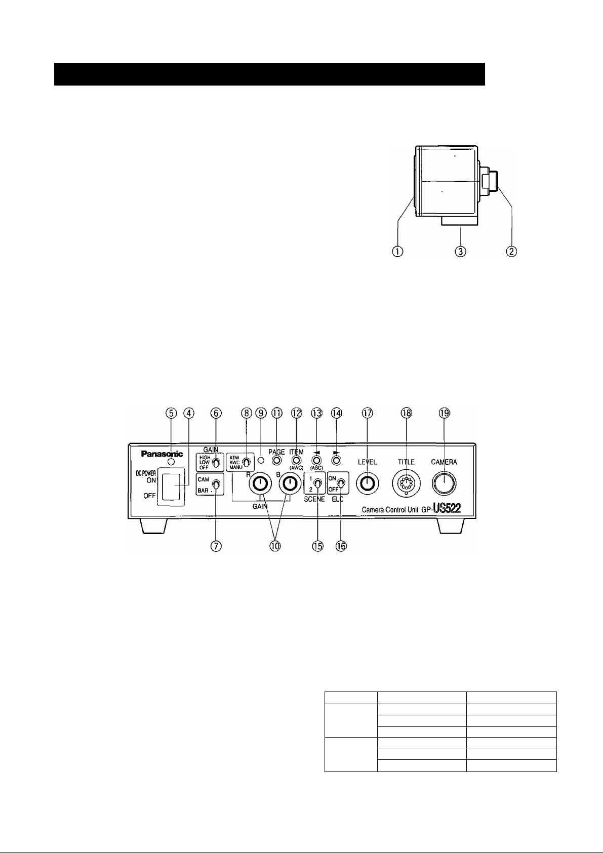
Camera Head
1. Lens Mount
This is used to attach the special C-mount lens for
GP-US522 and the C-mount lens for GP-US532.
2. Camera Cable Connector
This 24-pin connector is used to connect the
optional camera cable GP-CA522/4 to the camera
control unit.
3. Camera Mounting Screw Hole
This hole (1/4" - 20) is used to mount the camera
onto a mounting bracket.
Camera Control Unit
[Front Panel]
4. Power ON/OFF Switch (DC POWER ON/OFF)
This switch turns the power of this unit and power
supply for the camera head on or off.
5. Power Indicator (POWER)
This indicator lights up red when the power switch
is turned on.
6. Automatic/Manual Gain Selector Switch
(GAIN HIGH/LOW/OFF)
This selector is used to select the gain of video
amplifier as follows.
The mode can be selected in the SET UP menu.
Refer to page 14.
MODE
AUTO
MANU
-3-
POSITION OF SW
HIGH Maximum +18 dB
LOW
OFF
HIGH
LOW +9 dB (Fixed)
OFF
GAIN
Maximum + 9 dB
OdB
+ 18 dB (Fixed)
OdB
Page 6

7. Camera/Color Ваг Selector (CAM/BAR)
This selector is used to select either the video sig
nal or the SMPTE color bar signal which is output
from the video output connector (VIDEO), YC (SVIDEO) output connector or RGB (D-SUB, 9-pin)
output connector,
CAM :The video signal from the camera is output.
BAR : The SMPTE color bar signal is output.
Set this switch to BAR when making video monitor
adjustments and recording the color bar signal.
8. White Balance Selector (ATW/AWC/MANU)
This selector is used to select the white balance
mode from followings.
ATW ; In this mode, the color temperature is moni
tored continuously and thereby white balance
is set automatically.
AWC : In this mode, accurate white balance is
obtained.
The white balance settings are as follows:
1. Aim the camera at white chart.
2. Press the ITEM (AWC) button on the front
panel to set the white balance.
3. When the auto white balance is completed,
the auto warning indicator goes off after
blinking.
If the auto warning indicator is kept being lit,
follow the setting procedures above for auto
white balance setting again.
MANU : The white balance can be adjusted manu
ally by the red gain (R GAIN) and blue gain
controls (B GAIN).
9. Auto Warning Indicator
This indicator blinks while the white balance or
black balance is being automatically set. This indi
cator lights continuously when the white balance or
black balance is set improperly. In this case, follow
the auto white balance or black balance setting
procedure.
10. Red and Blue Gain Controls (R GAIN/B GAIN)
These controls are used to manually adjust the
white balance.
These controls only work when the white balance
selection switch (ATW/AWC/MANU) is set to
MANU.
Turn the controls clockwise to increase the red and
blue signal levels, and counterclockwise to
decrease.
12. Item Button (ITEM/AWC)
While the SET UP menu is displayed, this button is
used to move the cursor to the downward.
Normally, when the white balance selection switch
(ATW/AWC/MANU) is set to AWC, this button is
used to set the automatic white balance control
(AWC).
13. Left Button (-^/ABC)
While the SET UP menu is displayed, this button is
used to move the cursor to the left.
Normally, this button is used to set the automatic
black' balance control (ABC).
14. Right Button (►)
This button is used to move the cursor to the right
in the SET UP menu.
15. Scene Fite Selector (SCENE)
This selector is used to select the scene files.
16. Electronic Light Control ON/OFF Selector
(ELC ON/OFF)
This selector is used to select the electronic light
control from followings.
ON : In this position, the electronic light control
(ELC) mode is selected and the Electronic
Shutter Speed (SHUTTER) mode is interrupted.
OFF : In this position the shutter speed mode
(SHUTTER) is selected and electronic light
control (ELC) mode is interrupted.
Note :
• Confirm the setting of the ELC and SHUTTER
parameters on the SET UP menu.
17. Electronic Shutter Speed Control (LEVEL)
This control is used to set the target value of
Electronic Shutter Speed between 1/60 and
1/10 000 second together with ELC ON/OFF switch.
18. Title Input Connector (TITLE)
This connector is used to connect the optional
Character Generators WJ-KB30 or WJ-KB50.
Note:
The Black & White characters of the generator
are mixed with the video signal and are
obtained at VIDEO OUT, S-VIDEO (Y/C) OUT
and RGB/SYNC OUT connectors.
No colorization of the character is available.
11. Page Button (PAGE)
This button is used to display the SETUP MENU by
pressing for 2 seconds or more, and to change the
parameters in the SET UP MENU.
-4-
Page 7
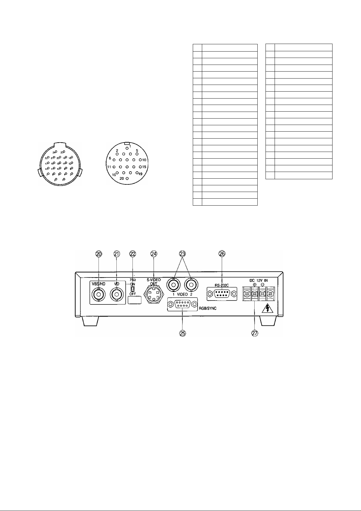
19. Camera Cable Connector (CAMERA)
This 20-pin connector is used for connection with
the cannera head via the optional camera cable
GP-CA522M.
Fasten the camera cable to this connector firmly.
If not, noise may be appeared.
— Caution:---------------------------------------------------
Connecting or disconnecting camera cable
to/from the camera control unit or camera
head must be done after turning off the
Power of the camera control unit.
For Camera
For ecu
Camera Head Side
-t-15V Input
1
Ground (GND)
2
Chip Select Input
3
4 +25 Input
-9V Input
5
B Signal Output
6
7 RGB Ground (GND)
8 Serial Data Input
Serial Clock Input
9
CCD Select Output
10
11 G Signal Output
12 R Signal Output
VD Input
13
14 CPOB Output
HD Input
15
+9V Input
16
17
+5V Input
PBLK Output
18
19 Not used
20 Not used
21 Not used
22 Not used
28MHz Input
23
24 Not used
Camera Control Unit Side
1 Ground (GND)
2 Not used
PBLK Input
3
4
+9V Output
-9V Output
5
6 28MHz Output
7
CPOB Input
RGB Ground (GND)
8
9 +5V Output
10 B Signal Input
11
Serial Clock Output
12 VD Output
Chip Select Output
13
14
+25 Output
15 R Signal Input
16 Serial Data Output
17 HD Output
18 G Signal Input
+ 15V Output
19
20 CCD Select Input
[Rear Panel]
20. Gen-tock Signal Input Connector (VBS/HD)
The color video signal of the camera is automatical
ly synchronized to the gen-lock signal (Composite
Signal, Black Burst Signal or Video Sync) when
either signal is supplied to this connector.
The gen-lock signal is used for system reference.
Caution :
If the gen-lock signal is jittery (as in the case of
a VCR playback picture), the camera can not
be synchronized properly.
(External HD and VD Mode)
The horizontal and vertical pulse of the color
video signal is synchronized to the external HD
fed to this connector and external VD fed to the
VD input connector.
21. Gen-Lock Signal Input Connector (VD)
Supply the external vertical drive (VD) pulse to this
connector,
22. Gen-Lock Video 75 ii Termination ON/OFF
Switch (75 a ON/OFF)
When looping through the gen-lock video signal
with BNC "T" adapter, set this switch to OFF. When
not looping through, set this switch to ON,
23. Video Output Connector (VIDEO 1,2)
A 1.0V[p-p]/75 composite video signal is provid
ed at this connector.
-5-
Page 8
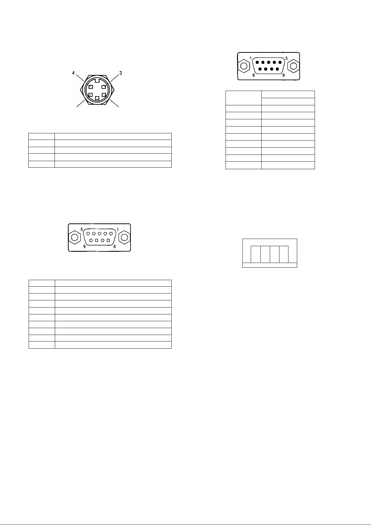
24. S-Video Output Connector (S-VIDEO OUT)
The luminance (Y) and chrominance (C) signals for
VCR or monitor are provided at this connector.
26. RS-232C Connector (RS-232C)
2 1
S-VIDEO OUT (Mini-DIN,4-pin)
Pin No.
1 Y Ground
2 C Ground
3
4 C Signal Output (0.286V[p-p](Burst Level)/75 £2)
Y Signal Output {0,714V[p-p](Y level)/75 ii)
Description
25. RGB/SYNC Output Connector (RGB/SYNC)
The red, green, blue, sync and composite video
signals are provided at this connector.
RGB/SYNC (D-SUB,9-pin)
Pin No
1
2 TXD
3 RXD
4
5 Ground
6 DTR
7
8
9 Ground
Signal
RS-232C
Ground
DSR
CIS
RTS
Note; Refer to the qualified system pasonnel or
system Installers for this connection.
27. 12V DC Input Terminals (12V DC IN)
These terminals accept an external DC po\wer
source supplying nominal power of 12V DC, 0.7A.
g]
Pin No. Description
1
2
3 Red (R) Output (0.7V[p-p]/75 ii)
4 Green (G) Output (0.7V[p-p]/75 £2)
5 Blue (B) Output (0.7V[p-p]/75 £2)
6 Composite Video Output (1,0V[p-p]/75 £i)
7
8 Ground (GND)
9
Ground( GND)
Ground (GND)
Sync (SYNC) Output (4,0V[p-p] or 0.3V[p-p]/75 £2)
Ground (GND)
Cautions :
1. Connect to 12V DC (11.5 V - 16 V) class 2
power supply only.
2. To prevent fire or electric shock hazard, use a
UL listed wire VW-1, Style 1007 cable for 12 V
DC input terminals.
-6-
Page 9

CONNECTIONS
Cautions :
1. Keep the DC POWER ON/OFF switch in the OFF
position until all connections have been properly
made.
2. Connect the camera head and camera control unit.
Internal Sync Operation
1. Connect the camera cable between the camera
head and the camera control unit,
2,. Connect the coaxial cable with BNC connectors
between the video output connector of the camera
control unit and the video monitor or VCR,
Coaxial
Cable
Video
Monitor
VIDEO
7St¡ 1 gHhZ
© ©
IN OUT
VTR or
Video Monitor
VIDEO
75tJ[B |hI-Z
© ©
IN OUT
ecu
X
VDfO
a
i
A
Gen-lock Operation
1. Connect the camera cable between the camera
head and the camera control unit.
2.
Connect the coaxial cable with BNC connectors
between the video output connector of the camera
control unit and the video input connector of
Special Effects Generator (SEG), and between the
VBS/HD input connector of the camera control unit.
ecu
3. Connect the power cable between the DC 12 V
input terminals and the 12 V DC power supply unit
(obtained locally),
• Calculation method of maximum cable length
between camera control unit and power supply unit
is as follows,
11.5 V DC < Va - (R X 0.42 X L) < 16 VDC
L : Cable length (meter)
R : Resistance of copper wire (ii/meter)
Va : DC output voltage of power supply unit
L standard = Va - 12 / 0.42 x R (meter)
L minimum ^ Va -16 / 0.42 x R (meter)
L maximum ^ Va - 11.5 / 0.42 x R (meter)
Cautions:
1. Connect to 12 V DC (11.5 V - 16 V) class 2
power supply only.
2. To prevent fire or electric shock hazard, use a
UL listed wire VW-1, Style 1007 cable for 12 V
DC input terminals.
Connect the power cable between the DC 12 V
input terminals and the 12V DC power supply unit
(obtained locally).
Cautions :
1. Connect to 12 V DC (11,5 V - 16 V) class 2
power supply only.
2. To prevent fire or electric shock hazard, use a
UL listed wire VW-1, Style 1007 cable for 12 V
DC input terminals.
-7-
Page 10

Mounting the Lens
Caution :
Keep the POWER ON/OFF switch of camera control
unit in the OFF position throughout the installation.
Lens Mount
1. Remove the front cap of the camera head and con
firm that the surface of the optical filter of the cam
era head is clean.
If the surface of the optical filter is dirty clean it up
with a blower brush which is for film camera lenses
(available at your local camera store).
2. Mount the C-mount lens by turning it clockwise
onto the lens mount of the camera head.
Caution :
• Do not use any lens which has more than 1/8"
(3.5mm) of protrusion for lens mounting. (GP-
US522)
• Do not open the lens iris wider than the F2.8
stops. (GP-US522)
• Do not open the lens iris wider than the F2.2
stops. (GP-US532)
special C-mount: Less than 1/8"
(Less than 3.5mm)
-8-
Page 11

SETUP
1. CAMERA SETUP MENU
This camera utilizes a user setup menu that is dis
played on-screen.
The setup menu contains various items that form a
tree-type structures as sho\wn belo\w.
It is described in the following section: “2. SETUP
OPERATION".
Note:
. The SET UP menu is output from the VIDEO 1,
2 connectors, the S-VIDEO OUT connector,
and the RGB/SYNC connector.
2. SETUP OPERATION
This camera utilizes a user setup menu (SET UP)
that is displayed on the monitor.
To set items on the SET UP menu, use the following
buttons on the front panel of the camera control
unit.
Page Button
GAIN
Page Button (PAGE):
This button used to display the SET UP menu.
Use this button to select an item.
Item Button (ITEM):
This button is used to move the cursor downwards.
Left Button {•<)
This button is used to move the cursor to the left.
Use this button to select or adjust the parameters
of the selected item. The parameter changes each
time this button is pressed.
Right Button(^)
This button is used to move the cursor to the right.
Use this button to select or adjust the parameters
of the selected item. The parameter changes each
time this button is pressed.
-9-
Page 12

the SET UP menu
PAGE button for a few seconds
** SET
CAMERA ID
FLD/FRH
ELC
SHUTTER
GAIN
SYNC
BLACK BAL
SCENE FILE
END
UP **
>OFF
♦OFF
♦SCENEl
FLD
OFF
AUTO
INT
ABC
j
• Editing the SET UP menu
To edit the SET UP menu (change settings), press
ifie ITEM button to move the cursor to an item, and
press ^ and ► to change its parameter. After
completing all the settings, move the cursor to END
at the bottom line, and press the PAGE button. The
new values are stored in the EEPROM (Electric
Erasable and Programmable Read Only memory).
These values remain valid until new values are
stored, even if the power of the camera control unit
is off.
All Reset Operation
All Reset allows you to reset all setup menu items
to the factory settings if you are unsure about the
correct settings. Proceed as follows:
1. Repeat the above procedures to display the
SET UP menu.
2. Move the cursor to END at the bottom line.
3. Press both < and ► for a few seconds. The
SET UP menu disappears on the monitor
screen and the auto warning indicator lights
red.
At this time, all adjustments and parameters are
reset to the factory default settings. The auto warn
ing indicator goes off if AWC or ABC is performed.
r
** SET UP **
CAMERA ID ♦OFF
FLD/FRM
ELC
SHUTTER
GAIN
SYNC
BLACK BAL
SCENE FILE
END
FLD
♦OFF
OFF
AXTTO
INT
ABC
♦SCENEl
\
>
-10-
Page 13

SEHING PROCEDURES
1. Camera Identification
(CAMERA ID)
You can use the camera identification (CAMERA ID) to
assign a name to the camera. The camera ID consists
of up to 16 alphanumeric characters. You can select
whether to have the camera ID displayed on the moni
tor screen or not.
** SET UP **
CAMERA ID
FLD/FRM
ELC
SHUTTER
GAIN
SYNC
BLACK BAL
SCENE FILE
END
To edit the CAMERA ID
1. Move the cursor to the CAMERA ID parameter.
2. Press the PAGE button. The CAMERA ID menu
appears. The cursor on the letter "A" starts blink
ing.
Character Cursor
ABCDEFGHIJKLM
NOPQRSTUVWXYZ
0123456789
O., =
+-*/%$
i
--
> SPACE
♦POSI RET END RESET 1
[♦OFF
FLD
*OFF
OFF
AUTO
INT
ABC
♦SCENEl
Area
— Command
To erase all characters in the editing area
Move the character cursor to RESET and press the
PAGE button. All characters in the editing area disap
pear.
To determine the display position of the CAMERA iD
1. Move the cursor to POSI, and press the PAGE but
ton. The display shown below appears and the
2. Move the CAMERA ID to the desired position by
pressing ► or the ITEM button,
3, Press the PAGE button to fix the position of the
CAMERA ID. The mode returns to the previous
CAMERA ID menu.
Notes:
• The CAMERA ID stops at the edges of the
monitor screen.
• The CAMERA ID moves faster if any of
•<,
► or
the ITEM button is kept pressed for a second
or longer.
To return to the SET UP menu
Move the cursor to RET and press the PAGE button.
The SET UP menu appears.
Editing Cursor -
----^3..........................
V
_____________________
D-
— Editing
y
Area
3. Move the character cursor to a character you want
by pressing ITEM, ^ or ►.
4. After selecting the character, press the PAGE but
ton. The selected character appears in the editing
area. (The editing cursor in the editing area moves
to the right automatically at this moment.)
5. Repeat the steps above until all characters are
edited.
To enter a blank space in the CAMERA ID
Move the character cursor to SPACE and press the
PAGE button.
To edit a specific character in the CAMERA ID
1. Move the character cursor to <- or -> then press
the PAGE button to move the editing cursor to the
character to be edited in the editing area.
2. Move the character cursor to the character area
and select a new character,
3. Press the PAGE button to determine the CAMERA
ID.
-11-
To display the CAMERA ID on the monitor screen
Move the cursor to CAMERA ID in the SET UP menu
and select ON.
2. Field/Frame Charging Mode Setting
(FLD/FRM)
You can select the charging mode from FIELD or
FRAME.
** SET UP **
CAMERA ID
FLD/FRM
ELC
SHUTTER
GAIN
SYNC
BLACK BAL
SCENE FILE
END
♦ OFF
[FLD
♦ OFF
OFF
AUTO
INT
ABC
«SCENE1
Page 14

1. Move the cursor to the FLM/FRM parameter.
2. Select FLM (field) or FRM (frame).
Note:
When FRM is selected, ELC is set to OFF auto
matically.
3. Electronic Light Control Setting
(ELC)
The electronic light control function eliminates inter
ference by strong background lighting which
makes the camera picture dark, such as a spot
light. In the ELC mode, more photometric weight is
given to the desired point of the screen (to where
the important object is located).
3. Move the cursor to the AREA parameter and select
the desired detection area. You can select the
desired detection area from followings.
ALL: All areas on the monitor screen are detected,
MANU: Detection areas are selectable manually.
See below for details,
CENTER: The photometric weight is given to the
center of the monitor screen.
S CIRCLE (Small Circle): The photometric weight
is given to the areas in the small circle of the
monitor screen.
M CIRCLE (Medium Circle): The photometric weight
is given to the areas in the medium circle of the
monitor screen.
L CIRCLE (Large Circle): The photometric weight
is given to the areas in the large circle of the
monitor screen.
** SET UP **
CAMERA ID
FLD/FRM
ELC
SHUTTER
GAIN
SYNC
BLACK BAL
SCENE FILE
EHD
3-1. ELC detection control area setting (ELC CONT)
1, Select ON for the ELC ON/OFF selector on the front
panel of the camera control unit. Then confirm the
ELC parameter is ON.
2. Move the cursor to the ELC parameter and press
the PAGE button.
The ELC CONT menu appears.
** ELC СОИТ **
AREA ;ALL
PEAK/AVE P--------1.
*OFP
FLD
t'ONl
OFF
AUTO
INT
ABC
♦SCENEl
Each time you press
changes as follows.
ALL—► MANU —► CENTER —* S CIRCLE (Small Circle)
u
M CIRCLE (Medium Circle) L CIRCLE (Large Circle)
ALL
or ►, the parameter
Detection Area
/
ПППППППП
ПППППППП
ШПППППП
□□□□□□□□
ПППППППП
.ПППППППП
CENTER
П
□
■■nnrirjg
/
\~
V
Detection Area
--
—
■■□ПППИ
□ □
S CIRCLE
i
□
Detection Area
/
!
□
— 50% Sensing
Area
—100% Sensing
Area
RET EHD
-12-
/
■
Ш
■
■ ■
Ш
■ ■
>
Page 15

M CIRCLE
n
□
□
■
Detection Area
/
n
■□□□□■I
innnnnni
L CIRCLE
{Large Circle)
Note: Detection areas are not displayed on the
monitor.
Detection Area
/
/
"Pi
A.
Press the PAGE button to mask that area. The-
mask turns white. (When the cursor is moved on an
area that has already been masked, the mask and
cursor start blinking.)
Masked Area
(WHITE)
/
7
)
Note: The area masked white will not be used in
the ELC detection.
5. Repeat the steps 3 and 4 to complete masking.
To cancel masking, move the cursor to that area
and press the PAGE button.
J
3-1-1. Manual setting of the ELC detection control
area (MANU)
You can mask areas on the monitor screen to block the
strong brightness manually. Follow the steps below:
Notes:
The manual mask setting field is only displayed on
VIDE01, 2 and S-VIDEO OUT.
It is not displayed on RGB/SYNC output.
1. Move the cursor to the AREA parameter on the ELC
CONT menu.
2, Select MANU and press the PAGE button. The
manual mask setting field appears.
3. Select the area where backlight is bright by
or the ITEM button.
6. After masking is completed, press the PAGE button
for a second or more. The ELC CONT menu
appears.
3-1-2. Peak and Average Weight Control
(PEAK/AVE)
1. Move the cursor to the PEAK/AVE parameter. The
"I” cursor starts blinking.
** ELC CONT **
AREA ALL
PEAK/AVE P... II.
RET END
2. Move the “I" cursor to set the detection value.
When the “I" cursor is moved to the P (peak) side,
the peak value is detected.
When the “I" cursor is moved to the A (average)
side, the average value is detected.
-13-
Page 16

3-2. AGC detection control area setting (AGC CONT)
1. Select OFF for the ELC ON/OFF selector on the
front panel of the camera control unit. Then confirm
the ELC parameter is OFF.
ELC
2. Move the cursor to the ELC parameter and press
the PAGE button.
The AGC CONT menu appears.
** AGC CONT **
AREA CALLI
PEAK/AVE P....I.
1. Move the cursor to the SFIUTTER parameter.
2. Select the shutter speed or MANU for manual set
ting from the following.
•MANU — OFF (1/60) —1/100 —1/250
l:
1/500 1/1000
•1/2000—1/4000
1/10000
□
D
3. When you select MANU, press the PAGE button.
The SHUTTER menu appears and the MANU SET
parameter starts blinking.
** SET UP **
CAMERA ID
FLD/FRH
ELC
SHUTTER
GAIN
SYNC
BLACK BAL
SCENE FILE
END
*OFF
FLD
*OFF
r*MANU
AUTO
INT
ABC
*SCENE1
Blinking
RET END
3.
Follow the same step 3 of “3-1. ELC detection con
trol area setting (ELC CONT)" to select the desired
detection area (AREA).
Follow the same steps 1 and 2 of “3-1-2. Peak and
Average Weight Control (PEAK/AVE)’’ to set the
detection value.
4. Electronic Shutter Speed Setting
(SHUTTER)
Note: When ON is selected for ELC on the SET UP
menu, this item is not available. To select the
electronic shutter speed, select OFF for ELC
on the SET UP menu.
You can select the electronic shutter speed of 1/100,
1/250, 1/500, 1/1 000, 1/2 000, 1/4 000 or 1/10 000 sec
onds. Also manual setting is available.
** SET UP **
CAMERA ZD
FLD/FRM
ELC
SHUTTER
GAIN
SYNC
BLACK BAL
SCENE FILE
END
•OFF
FLD
•OFF
[OFF
AUTO
INT
ABC
•SCENE1
Select the desired electronic shutter speed by
► . The adjustable range is 1/525-261/525 lines.
5. Gain Control Setting (GAIN)
You can set the gain (brightness level portion of an
image) to automatic level adjustment (AUTO) or
manual level adjustment (MANU).
** SET
CAMERA ID
FLD/FRM
ELC
SHUTTER
GAIN
SYNC
BLACK BAL
SCENE FILE •SCENEl
END
Move the cursor to the GAIN parameter.
Select AUTO or MANU. The gain of the video
amplifier is changed according to the position of
the automatic/manual gain selector
(HIGH/LOW/OFF) on the front panel of the camera
control unit.
UP **
•OFF
•OFF
fAUTO
FLD
OFF
INT
ABC
or
-14-
Page 17

When you select AUTO, the gain of the amplifier
changes as follows.
Position
HIGH
LOW
Maximum +18 dB
Maximum +9 dB
Gain
OFF OdB
When you select MANU, the gain of the amplifier
changes as follows.
Position Gain
HIGH
LOW
OFF
+ 18 dB (Fixed)
+9 dB (Fixed)
OdB
6. Synchronization Setting (SYNC)
This model accepts the VBS signal (color compos
ite video or blackburst signal) and VS signal (BA^
composite video or composite sync signal ) for the
gen-lock operation.
This camera also accepts the vertical drive pulse
(VD) with horizontal drive pulse (HD), and the verti
cal drive pulse (VD) only.
• The VS gen-lock mode has its own menu for hori
zontal and subcarrier phase adjustaments. When
the cable length of the video output or the gen-lock
input is changed, the horizontal phase must be re
adjusted.
• When the HD/VD or VD pulse is to be used, supply
them to the VBS/HD connector and the VD connec
tor on the rear panel of the camera control unit.
6-1. Internal Sync Mode (INT)
RGB Sync Output Level Adjustment (RGB SYNC)
1. Move the cursor to the SYNC parameter,
2. Press the PAGE button. The SYNC menu appears
on the monitor screen.
3. Move the cursor to the RGB SYNC parameter.
4. Select 4.0V or 0.3V according to the RGB monitor
input level.
** SET
CAMERA ID *OFF
FLD/FRM
ELC
SHUTTER
GAIN
SYNC ¿INTj
BLACK BAL
SCENE FILE *SCENE1
END
UP **
FLD
*OFF
OFF
AUTO 3,
ABC
J
Imporant Notices:
• The priority for the sync mode is as follows:
1. Color composite video signal (VBS)
2. BAA/composite video signal (VS)
3. HD/VD signal
4. VD signal
5. Internal sync (INT)
• When the internal sync (INT) mode is to be used,
no gen-lock input signal should be supplied to the
gen-lock input connector on the rear panel of the
camera contrrol unit.
• When the VBS or VS gen-lock mode is to be used,
supply the gen-lock input signal to the gen-lock
input connector on the rear panel of the camera
control unit.
• The VBS gen-lock mode has its own menu for hori
zontal and subcarrier phase adjustments. When the
cable length of the video output or the gen-lock
input is changed, horizontal and subcarrier phase
must be re-adjustable.
6-2. VBS Gen-lock Mode (EXT(VBS))
1.
Move the cursor to the SYNC parameter.
2.
Connect the coaxial cable for the blackburst or
composite color video signal to the gen-lock input
connector.
Confirm that the INT parameter changed to
EXT(VBS) on the menu.
Caution: The gen-lock input signal should meet the
EIA RS-170A specifications and should not
contain jitter, such as a VCR playback signal,
as it could disturb synchronization.
** SET UP **
CAMERA ID
FLD/FRM FLD
ELC
SHUTTER
GAIN
SYNC r*EXT(VBS)
BLACK BAL
SCENE FILE
END
•OFF
♦OFF
OFF
AUTO
ABC
♦SCENEl
>
-15-
Page 18

4. After confirming that the cursor is on EXT(VBS),
press the PAGE button. The SYNC menu appears
on the monitor screen.
5. Move the cursor to the RGB SYNC parameter.
6. Select 4.0V or 0,3V according to the RGB monitor
input level.
Horizontal Phase Adjustment (H PHASE)
1. Move the cursor to H PHASE. The cursor starts
blinking,
2. Supply the video output signal of the camera to be
adjusted and the reference gen-lock input signal to
a dual-trace oscilloscope.
3. Set the oscilloscope to the horizontal sync portion
on the oscilloscope.
4. Adjust the horizontal phase by pressing or ►.
The adjustable range is 0-1.5 [is.
Note: To reset H PHASE to the values preset at the
factory, press M and ► simultaneously. The H
PHASE is reset at the factory setting.
Subcarrier Coarse Phase Adjustment (SC COARSE)
1, Move the cursor to SC COARSE parameter on the
SYNC menu. The cursor starts blinking.
Press or ► to match the color (hue) of the cam
2,
era’s video signal, when observed at the output of
the Special Effect Generator (SEG) or Switcher, as
closely as possible the color of the original scene.
(The SC COARSE adjustment can be incremented
in steps of 90 degrees (4 steps) by pressing or
►.)
Note;
After the fourth step, the adjustment returns to
the first step.
Notes;
• When the T cursor reaches the ■+' end, it jumps
back to ■-*. At the same time, SC COARSE is incre
mented by one step to enable a continuous adjust
ment. The reverse takes place when the T cursor
reaches
theend.
For more accurate adjustment, supply both the
original camera video output signal and the effect
output video signal (program output video signal)
of the special effects generator (SEG) to a vectorscope and compare the chroma phase of both
signals.
• To reset SC FINE to the values preset at the facto
ry, press M and ► simultaneously. The SC FINE is
reset at the factory setting,
6-3. VS Gen-lock Mode (EXT(VS))
1. Move the cursor to the SYNC parameter.
2. Connect the coaxial cable for the composite sync
or composite B/W video signal to the gen-lock input
connector.
Confirm that the INT parameter changed to
3.
EXT(VS) on the menu.
Caution; The gen-lock input signal should meet the
EIA RS-170 specifications and should not con
tain jitter, such as a VCR playback signal, as it
could disturb synchronization.
** SET
CAMERA ID
FLD/FRH
ELC
SHUTTER
GAIN
SYNC
BLACK BAL
SCENE FILE
END
UP **
*OFF
FLD
*OFF
OFF
AUTO
r*EXT(VS)
ABC
*SCENE1
4. After confirming the cursor is on EXT (VS), press
the PAGE button. The phase adjustment menu
appears on the monitor screen.
1
1 (1 - - 4); 0 degrees
I
2(1-' 4): 90'degrees
I
3 (1 - - 4); 180 degrees
I
4 (1 - - 4): 270 degrees
Subcarrier Fine Phase Adjustment (SC FINE)
1. Move the cursor to SC FINE on the SYNC menu. The
cursor starts blinking.
2. Press or ► to match the color (hue) of the came
ra's video signal, when observed at the output of
the Special Effect Generator (SEG) or Switcher, as
closely as possible the color of the original scene.
The SC FINE adjustment has a range of 90 degrees
of color shift.
Move the cursor to the RGB SYNC parameter.
Select 4.0V or 0.3V according to the RGB monitor
input level.
Move the cursor to H PHASE. The cursor starts
blinking.
-16-
Page 19

8. Supply the video output signal of the camera to be
adjusted and the reference gen-lock input signal to
a dual-trace oscilloscope,
9. Set the oscilloscope to the horizontal rate and
expand the horizontal sync portion on the oscillo
scope.
10. Adjust the horizontal phase by pressing or ►.
The adjustable range is 0-1.5 ps.
6-4. External HD/VD Mode (HDA^D)
Move the cursor to the SYNC parameter.
Connect the coaxial cable for the external HD and
VD signal to the gen-lock input connector and the
VD input connector respectively.
Confirm that the INT parameter changed to EXT
(HA/) on the menu.
Move the cursor to the RGB SYNC parameter.
Select 4.0V or 0.3V according to the RGB monitor
input level.
7. Black Balance Setting (BLACK BAL)
In low light condition, correct setting of the black
balance is required for producing correct colors.
Once the black balance setting has set correctly,
the setting maintained in a memory.
This setting will not be lost even if the camera con
trol unit Is turned off. However, for best results, it is
recomended that the black balance adjustment be
carried out the camera has not been used for a
long period of time.
The black balance control mode can be selected
between auto black balance control (ABC) on the
front panel and manual control (MANU) on this
menu.
7-1. Auto Black Balance Setting (BLACK BAL)
1. Move the cursor to the BLACK BAL parameter and
select ABC.
** SET UP **
CAMERA ID *OFF
FLD/FRM FLO
ELC
SHUTTER OFF .
GAIN
SYNC
BLACK BAL
SCENE FILE •SCENEl
END
•OFF
AUTO
[^EXT(H/V)
ABC
>
6-5. External VD Mode (VD)
1, Move the cursor to the SYNC parameter and select
INT.
Connect the coaxial cable for the external VD sig
2.
nal to the VD input connector.
3. Confirm that the INT parameter changed to EXT
(VD) on the menu.
4. Move the cursor to the RGB SYNC parameter.
5. Select 4.0V or 0.3V according to the RGB monitor
input level.
r
** SET UP **
CAMERA ID •OFF
FLO/FRH
ELC
SHUTTER
GAIN AUTO
SYNC
BLACK BAL ABC
SCENE FILE
END
FLD
•OFF
OFF
r*EXtiVD)
*SCENE1
** SET UP **
CAMERA ID
FLD/FRM
EDC
SHUTTER
GAIN
SYNC
BLACK BAL
SCENE FILE
END
*OFF
FLD
*OFF
OFF
AUTO
INT
lABC
*SCENE1
2. Attach the lens cap on the camera lens.
3. Move the cursor to END and press the PAGE but
ton to close the SET UP menu.
4. Press the M (ABC) button on the front panel of the
camera control unit.
The auto black balance setting is performed.
5. When the auto black balance is completed, the
auto warning indicator goes off after blinking. If the
indicator is kept being lit, follow the setting proce
dures above for auto black balance setting (ABC)
again.
7-2. Manual Black Balance Control Setting(MANU)
1. Move the cursor to the BLACK BAL parameter and
select MANU.
•• SET UP **
CAMERA ID •OFF
FLD/FRM FLD
ELC •OFF
SHUTTER OFF
GAIN AUTO
SYNC
BLACK BAL
SCENE FILE
END
INT
[iMANU
•SCEN]
-17-
Page 20

2. Press the PAGE button. The BLACK BAL menu
(manual black balance setting menu) appears.
2. Press the PAGE button. The SCENE FILE menu
appears.
** SCENE FILE 1 ** PI
GAMMA ETTTTiTTTO
AUTO KNEE ON
TOTAL-PED CHROMA GAIN DTL BAND - .1.+
HDTL GAIN - ....I.... +
VDTL GAIN RED DTL OFF
NEXT RET END
_ _
I..-
_______I_
_______I_
+
+
3. Move the cursor to R-PED. The cursor starts blink
ing,
4. Attach the lens cap on the camera lens'.
5. While observing the vector scope or waveform
monitor, adjust the red pedestal level (R-PED) by
^ or ► for minimum carrier.
6. Move the cursor to B-PED. The cursor starts blink
ing.
7. While observing the vector scope or waveform
monitor, adjust the blue pedestal level (B-PED) by
or ► for minimum carrier.
Note: To reset the pedestal level to the factory set
ting, move the cursor to R-PED or B-PED and
press the M and ► button simultaneously for a
second or more. The R-PED or B-PED level
value reset to the factory setting.
8. Scene File Setting (SCENE FILE)
This menu allows for you to adjust and set 17 items
for the video signal of camera to meet your
requirment.
There are two scene files so that two settings are
memorizable.
Switch the SCENE FILE 1 and the SCENE FILE 2 by
the scene file selector on the front panel of the
camera control unit.
1. Move the cursor to the SCENE FILE parameter and
select SCENE!
** SET
CAMERA ID ♦OFF
FLD/FRM FLD
ELC
SHUTTER OFF
GAIN
SYNC INT
BLACK BAL
SCENE FILE
END
UP **
♦OFF
AUTO
ABC
[♦SCENEl
>
** SCENE FILE 1 ** P2
CLEAN DNR
2D LPF OFF
MATRIX R-G
MATRIX R-B MATRIX G-R
MATRIX G-B
MATRIX B-R MATRIX
HUE NEXT RET END
B-G - . . . .1
[OFF
__ _I____
-
__ _
I, . . .
-
__ _I____
__ _
I. . . .
__ _I____
-
There are 2 pages for SCENE FILE (PI and P2),
On page 1 (PI), you can set the following items:
• Gamma Correction (GAMMA)
• Auto Knee ON/OFF (AUTO KNEE)
• Total Pedestal Level Control (TOTAL-PED)
• Chrominance Level Control (CHROMA GAIN)
• Detail Band Control (DTL BAND)
• Horizontal Detail Gain Control (HDTL GAIN)
• Vertical Detail Gain Control (VDTL GAIN)
On page 2 (P2), you can set the following items:
• Red Detail ON/OFF (RED DTL)
• Clear Digital Noise Reduction Control (CLEAN
DNR)
• 2 Dimention Low Pass Filter (2D LPF)
• 6 Chroma Matrix Controls
(MATRIX R-G)
(MATRIX R-B)
(MATRIX G-R)
(MATRIX G-B)
(MATRIX B-R)
(MATRIX B-G)
• Chroma Phase Control (HUE)
To turn the page
Move the cursor to NEXT and press the PAGE button.
To return to the SET UP menu
Move the cursor to RET and press the PAGE button.
-18-
Page 21

8-1. Gamma Correction (GAMMA)
1. Move the cursor to GAMMA parameter. The “I” cur
sor starts blinking.
2. While observing the waveform monitor or the color
video monitor, adjust the gamma level.
If the "I" cursor is on the end of the side, the
gamma correction is set to OFF.
If the “I" cursor is on the end of the side, the
black strech (BLACK STRET) is set.
8-2. Auto Knee ON/OFF (AUTO KNEE)
1. Move the cursor to the AUTO KNEE parameter,
2. Select ON or OFF for the auto knee mode.
8-3. Total Pedestal Level Control (TOTAL-PED)
1. Move the cursor to the TOTAL-PED parameter. The
"I" cursor starts blinking.
2. While observing the waveform monitor or the color
video monitor, adjust the total pedestal level (black
level).
Move the "I" cursor to the
“+"
side to obtain the
brightness.
Move the “I" cursor to the side to obtain the
darkness.
8-4. Chrominance Level Control (CHROMA GAIN)
1, Move the cursor to CHROMA GAIN parameter. The
“I” cursor starts blinking.
2. While observing the waveform monitor or the color
video monitor, adjust the chroma level.
8-5. Detail Band Control (DTL BAND)
1. Move the cursor to the DTL BAND parameter. The
“I" cursor starts blinking.
2. While observing the color video monitor, adjust the
aperture level.
Move the “I" cursor to the side to obtain the
higher frequency.
Move the "I" cursor to the side to obtain the
lower fequency.
8-6. Horizontal Detail Gain Control (HDTL GAIN)
1. Move the cursor to the HDTL GAIN parameter. The
‘T’ cursor starts blinking,
2. While observing the color video monitor, adjust the
aperture level.
Move the "I" cursor to the “4" side to obtain the
sharpness.
Move the “I" cursor to the side to obtain the
softness.
If the "I” cursor is on the end of the side, the
horizontal detail level is set to OFF.
8-7. Vertical Detail Gain Control (VDTL GAIN)
1. Move the cursor to the VDTL GAIN parameter. The
“I" cursor starts blinking.
2. While observing the color video monitor, adjust the
aperture level.
Move the "I” cursor to the “4" side to obtain the
sharpness.
Move the “I" cursor to the side to obtain the
softness.
If the "I" cursor is on the end of the side, the
vertical detail level is set to OFF.
8-8. Red Detail ON/OFF (RED DTL)
1. Move the cursor to the RED DTL parameter.
2. Select ON or OFF for the RED DTL mode.
When ON is selected, the red detail is enhanced.
8-9. Clear Digital Noise Reduction Control
(CLEAN DNR)
1. Move the cursor to the CLEAN DNR parameter.
2. Select OFF, LOW or HI for the CLEAN DNR mode.
8-10. 2 Dimentlon Low Pass Filter (2D LPF)
1. Move the cursor to the 2D LPF parameter.
2. Select ON or OFF for the 2D LPF mode,
8-11.6 Chroma Matrix Controls
(MATRIX R-G)
(MATRIX R-B)
(MATRIX G-R)
(MATRIX G-B)
(MATRIX B-R)
(MATRIX B-G)
1. Move the cursor to the desired matrix item. The 'T'
cursor starts blinking.
2. While observing the vectorscope or the color video
monitor, adjust the matrix level.
8-12. Chroma Phase Control (HUE)
1. Move the cursor to the HUE parameter. The "I" cur
sor starts blinking,
2. While observing the vectorscope or the color video
monitor, adjust the chroma phase (hue).
To reset to the factory setting
Any of the above settings except AUTO KNEE, RED
DTL, CLEAN DNR and 2D LPF, can be reset to the fac
tory settings.
Move the cursor to the desired item and press ^ and
► simultaneously for a second and more.
-19-
Page 22

PREVENTION OF BLOOMING AND SMEAR
When the camera is aimed towards spotlights or other
bright lights or light reflecting objects, smear or bloom
ing may appear.
Therefore the camera should be operated carefully in
the vicinity of extremely bright objects to avoid smear or
blooming.
If the camera is aimed at the sun or very bright light,
such as laser beam, for a long period of time, the CCD
image sensor may be burned in and blemishes(white or
black dots) appears on the monitor screen
Ring type flare
-20-
Page 23

SPECIFICATIONS
Pick-up System:
Image Sensor:
Pixels:
Scanning Standard:
Synchronizing System:
Video Outputs:
Required Illumination:
Minimum Illumination:
Signal-to-Noise Ratio:
Horizontal Resolution:
White Balance:
Black Balance:
Color Bar:
Electronic Shutter:
Gain Selection:
Switches:
Controls:
Computer Interface
Lens Mount:
Power Source:
Power Consumption:
Ambient Operating Temperature:
Ambient Operating Humidity:
Dimensions
Camera Head:
(Excluding Mounting Adaptor)
CCU:
(Excluding Rubber Foot and Connector) [8-1/8" (W) x 1-11/16" (H) x 9-1/2" (D)]
Weights
Camera Head: 110 g (0.24 lbs)
CCU: 1.7 kg (3.74 lbs)
Micro prism system
Three 1/2" interline transfer (IT) super high sensitivity CCDs (GP-US522)
Three 1/3" interline transfer (IT) super high sensitivity CCDs (GP-US532)
768 (Horizontal) x 494 (Vertical)
525 lines, 60 fields, 30 frames
Internal or External (Gen-Lock), automatically switchable
Internal: EIA standard
External (Gen-Lock) Input: VBS/VS/HD/VD is selectable
SC Phase for Gen-Lock (VBS): Free adjustable over 360°
H Phase for Gen-Lock (VS): Adjustable
Video Output: BNC Connector x 2
1.0V[p-p] NTSC composite/75
Y/C (S-VIDEO) Output: S-VIDEO Connector x 1
0,714V[p-p] Luminance level (Y)/75 Q (S-VIDEO connector)
0.286V[p-p] Burst Level (C)/75 Q (S-VIDEO connector)
RGB/SYNC Output: D-SUB 9-pin Connector x 1
R/G/B; 0.7V[p-p] each/75
SYNC: 4V[p-p]/75 П or 0.3V[p-p]/75 П selectable
VIDEO: NTSC composite/75
2000 lx at F11.0, 3200 К (GP-US522)
2000 lx at F8.0, 3200 К (GP-US532)
5 lx (0.5 foot candle) at F2.8 with -t-18 dB gain, 30 IRE level (GP-US522)
9 lx (0.9 foot candle) at F2.2 with -i-18 dB gain, 30 IRE level (GP-US532)
62 dB (Typical, Luminance) without aperture and gamma
800 lines at center (Y signal) (GP-US522)
750 lines at center (Y signal) (GP-US532)
ATW (Automatic Tracing White Balance Control), AWC (Automatic White
Balance Control) and Manual
ABC (Automatic Black Balance) and Manual
SMPTE color bar with 7.5% set-up
AUTO: Adjustable between 1/60 - 1/10 000s
STEP: Selectable 1/60(OFF),1/100, 1/250, 1/500, 1/1 000, 1/2 000,
1/4 000 and 1/10 000s
SYNCHRO SCAN: Selectable from 1/525 to 254/525 line
AGC and Gain Up (Selectable)
Power On/Off (POWER), Camera/Color Bar Selection (CAM/BAR),
Gain Up Selection (OFF/LOW/HIGH (0/+9/-i-18 dB)), White Balance Selection
(ATW/AWC/MANU), ELC (Electronic Light Control) On/Off, PAGE, ITEM (AWC),
(ABC) and ►
R Gain, В Gain and ELC LEVEL
RS-232C : D-SUB 9-pin Connector x 1
Special C Mount (GP-US522)
C Mount (GP-US532)
12 V DC
8.4 W
32°F- 113°F (0°C - -ь45°С)
30 % - 90 %
34 (W) X 44 (H)x 52(D) mm
[1-5/16- (W) X 1-11/16- (H) X 2- (D)]
(206,5 (W) X 44 (H) X 250 (D) mm)
Q
Q
Dimensions and Weights indicated are approximate
Specifications are subject to change without notice
-21-
Page 24

OPTIONAL ACCESSORIES
CamGra Cable
..............................................................
GP-CA522/4
Character Generators .......................................WJ-KB15, WJ-KB50
Panasonic
Medical & Industrial Video Company
A Division of Panasonic Broadcast & Teievision Systems Company
A Unit of Matsushita Electric Corporation of America
Executive Office: One Panasonic Way 3E-7, Secaucus, New Jersey 07094
Regional Offices:
Northeast: 43 Hartz Way, Secaucus, NJ 07094 (201) 348-7303
Southeast: 1225 Northbrook Parkway, Suite 1-160, Suwanee, GA 30174 (770) 338-6835
Midwest: 1707 North Randall Road, Elgin, tL 60123 (847) 468-5200
Southwest: 8105 Beltsline Road, Suite 100, Irving TX 75063 (214) 915-1333
Western: 6550 Katetia Ave., Cypress, CA 90630 (714) 373-7265
PANASONIC CANADA INC.
5770 Ambler Drive, Mississauga, Ontario, L4W 2T3 Canada (905)624-5010
PANASONIC SALES COMPANY
DIVISION OF MATSUSHITA ELECTRIC OF PUERTO RICO, INC.
San Gabriel Industrial Park, 65th Infantry Ave. KM, 9.5 Carolina. P.R. 00630 (809)750-4300
N0897-1107 YWV8QA4737BN
Printed in Japan
® 30
 Loading...