

Page 1
Technical Guide
Technical Guide
Troubleshooting Handbook
Troubleshooting Handbook
Model : TH-42PZ80U
TH-46PZ80U
TH-50PZ80U
TH-42PZ85U
TH-46PZ85U
TH-50PZ85U
TH-42PZ800U
Plasma
Plasma
(GPH11DU Chassis)
(GPH11DU Chassis)
HD Models
HD Models
TH-46PZ800U
TH-50PZ800U
TH-46PZ850U
TH-50PZ850U
Panasonic Technology and Service Company
National Training
Page 2

This page is purposely left blank.
2
Page 3
Table of Contents
Subject Page
Connector’s Location (TH-42PX80U)
Power LED’s Response to Shutdown Operation
LED blinks 1 time
LED blinks 2 times
LED blinks 3 times
LED blinks 4 times
LED blinks 5 times (Quick Troubleshooting)
LED blinks 5 times
LED blinks 6 times
SU/SD Board Isolation Procedure
LED blinks 7 times
LED blinks 8 times
LED blinks 9 times
LED blinks 10 times before pressing the power button
LED blinks 10 times after pressing the power button
LED blinks 11 times
LED blinks 12 times
5
7
8
9-11
12
13
14
15 - 18
19
20
21
23
24
25 - 27
28 - 29
30
31
Subject
No Sound
Troubleshooting for Picture Problems
Diagnostic Method for Troubleshooting PDP
Television
Troubleshooting for Picture Trouble
Diagnosis for Picture Problem (All Over the Screen)
Diagnosis of Vertical Line Problem
Picture Trouble at Upper or Lower half
Picture Trouble at Right or Left half (50 Inch)
Picture Trouble at Right or Left half (42/37 Inch)
Picture Trouble in 50 Inch Models
Picture Trouble all Over the Screen
Examples of Symptoms and Remedies
Self-check Procedure
Reset
Driver Setup Adjustment
Page
35
38
39
40
42
43
44
45
46
47
48
50
56
56
57
LED blinks 13 times
No Power / Dead
32
33 - 34
3
Page 4
Introduction
<Introduction>
1. Basic concept of how to determine the defective board
1) Verification of voltages
Normally, when there is a power problem, shutdown occurs immediately.
So, to resolve a power problem, voltage checks are necessary before shutdown.
2) Check if the power comes up after disconnecting the board under suspicion.
If power comes up (*) after disconnecting a board, the board is defective.
(*) “Power comes up” equals “no shutdown”.
2. Troubleshooting Video and Audio problems
3. Examples of video problems
4. Adjustment after PCB exchange
1) After exchanging the following boards, voltage adjustment is required.
P board, SC board, SS board => Please refer to the “Service Manual”.
4
Page 5
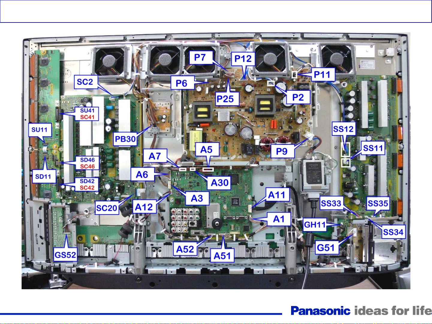
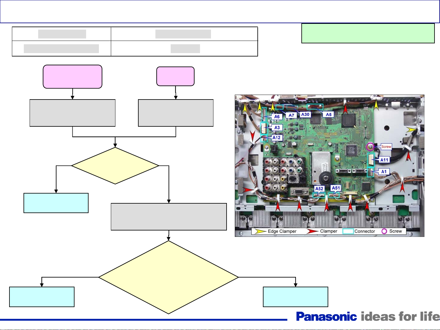
Connector’s Location (TH-42PZ85U)
Figure 1
5
Page 6
1. Troubleshooting Shutdown Problems
CAUTION: Some steps requires removal of connectors and
sometimes PC boards removal. Do not let the TV run for more
than 30 seconds while connectors or boards are disconnected.
6
Page 7
Power LED’s Response to Shutdown Operation
<LED Blinking timing>
Number of blinks Contents Check point
Communication Error with
1
2 15V SOS D
3 3.3V SOS D
4 Power Supply SOS P
5 5V SOS D
Microcomputer
D, A
6
7
8
9
10
11 Fan SOS PB, A
12 Sound SOS A
13
SC Energy recovery SOS
SC floating voltage SOS
SS Energy recovery SOS
Panel Configuration SOS
Sub 5V SOS, Main 3.3V SOS, DTV9V
SOS, Tuner SOS
Communication Error with Peaks
Lite-2
SC, D, P
SC, SU, SD, D, P
SS, D, P
D
A
A
7
Page 8
LED blinks 1 time
Trouble Mode
Communication Error
TH-42PZ80/85/800U
TH-46PZ80/85/800U
TH-50PZ80/85/800U
Disconnect A52 on the A
Board (See Figure 1). Plug
in the TV and turn it on
No Yes
Replace the GS
board
Defective Board
D, GS, A
TH-46PZ850U
TH-50PZ850U
Disconnect A9 on the A
Board. Plug in the TV
and turn it on
Is the power
LED still
blinking?
Unplug the TV and disconnect
connectors P6 and P7 on the P Board
(See Figure 1). Plug in the TV.
Warning: Disconnect AC Power prior t o
making any disconnection or connection
A board Connectors Location
Replace the D
board
No
Is the TV turning on by
itself with the following
conditions?
Power LED = Off
SC LED= On
SS LED = ON
Figure 2
Yes
Replace the A
board
8
Page 9
LED blinks 2 times
Trouble Mode
15V down SOS
Defective Board (Possibility)
P, A, SC, SS Board (P > A, SC, SS)
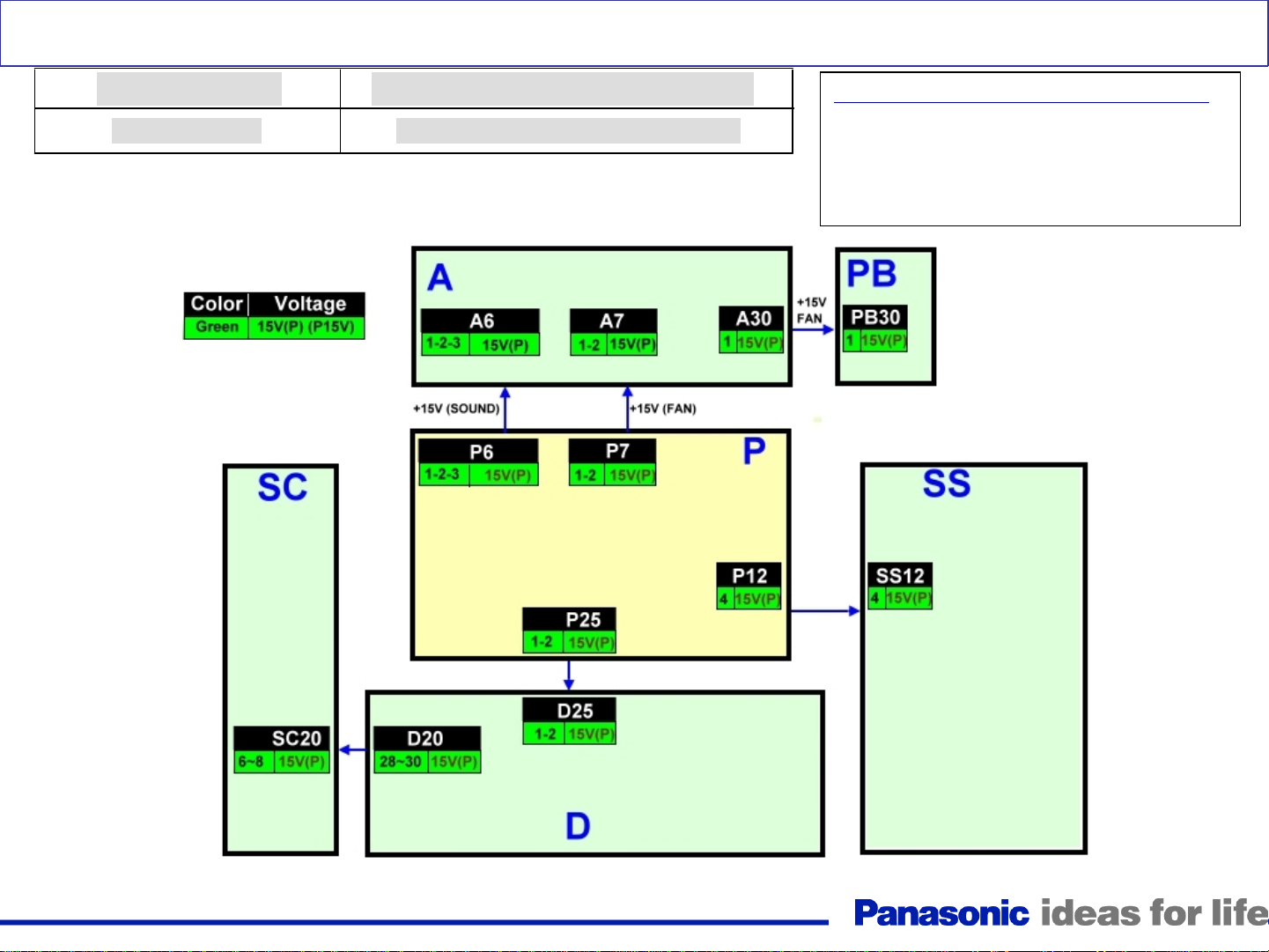
P15V Distribution
2 Blinks Condition can be caused by:
• Missing P15V
• A short of the P15V
• Wrong diagnostic by the D board
Figure 3
9
Page 10
LED blinks 2 times
Trouble Mode
15V down SOS
Plug in the TV and turn it on. Measure
the voltage at pin 1 of connector P7
No
Replace
The P board
Is there
15V
present?
Defective Board (Possibility)
P, A, D, SC, SS, PB Board (P > A, SC, SS, PB)
Unplug the TV and check the resistance between
pin 1 of connector P7 and ground (Chassis)
Yes
Replace
The D board
Is there a
short
circuit?
Reconnect P12 and measure the
resistance between pin 1 of
connector P7 and ground (Chassis)
YesNo
Warning: Disconnect AC Power prior t o
making any disconnection or connection
Unplug connectors P6, P7, P12, and P25 on the P
board. Measure the resistance between pin 1 of
connector P7 and ground (Chassis)
No
Is there a
short
circuit?
Yes
Replace
The P board
Reconnect P25 and measure the
resistance between pin 1 of
connector P7 and ground (Chassis)
No
Go to the
Next slide (A)
Is there a
short
circuit?
Yes
No
Disconnect SC20 on the SC board
and measure the resistance between
pin 1 of connector P7 and ground
(Chassis
10
Is there a
short
circuit?
Yes
Replace
The SS board
Go to the
Next slide (B)
Page 11
Continue from the
previous slide (A)
Reconnect P6 and measure the
resistance between pin 1 of
connector P7 and ground (Chassis
Continue from the
previous slide (B)
No
Is there a
short
circuit?
Yes
No
Is there a
short
circuit?
Is there a
short
circuit?
No
Reconnect P7 and measure the
resistance between pin 1 of
connector P7 and ground (Chassis)
Replace
The D board
Yes
Yes
Replace
The A board
Disconnect PB30 on the PB board
and measure the resistance between
pin 1 of connector P7 and ground
(Chassis)
No
The SC board
Is there a
short
circuit?
Replace
Yes
Replace
The D board
Replace
The PB board
Replace
The A board
11
Page 12
LED blinks 3 times
Trouble Mode
3.3V down SOS
Defective Board
D Board
Replace the D board
Warning: Disconnect AC Power prior t o
making any disconnection or connection
12
Page 13
LED blinks 4 times
Trouble Mode
Power Supply SOS
Primarily P board followed by D board
Defective Board
4 blinks condition can be caused by:
An abnormal increase in any of the voltages generated
by the power supply (Vsus, Vda, P15V, P5V, STB5V)
Warning: Disconnect AC Power prior t o
making any disconnection or connection
Turn the TV on.
Is pin
Yes No
12 of CN P25
on the P
board high
before the TV
shuts down?
13
D BoardP Board
Page 14
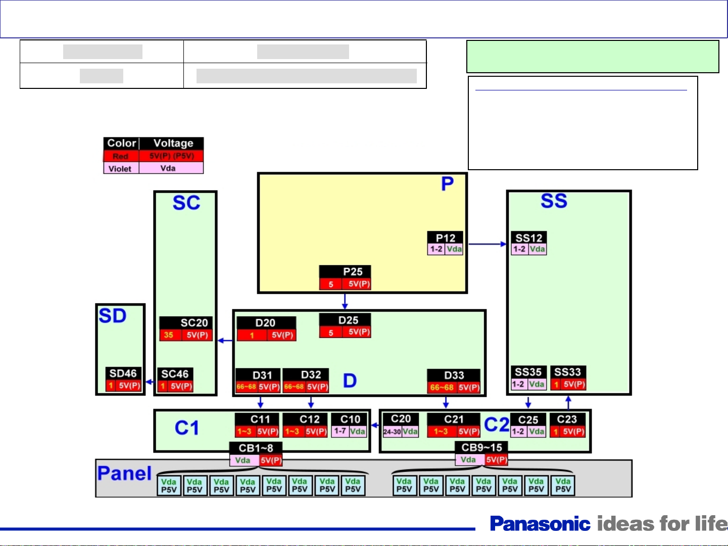
LED blinks 5 times
Trouble Mode
5V SOS
Defective Board
P, D, Cs, SC, SD, SS, D board or Panel
P5V and Vda Distribution
Warning: Disconnect AC Power prior to making any
disconnection or connection
5 blinks condition can be caused by:
• Missing P5V
• A short of the P5V
• A short of the Vda line (Note: missing
Vda from the P board does not cause 5
blinks)
• Wrong diagnostic by the D board
Figure 4
14
Page 15
LED blinks 5 times (Quick Troubleshooting)
Trouble Mode
5V SOS
Defective Board
P, D, Cs, SC, SS, D board or Panel
Disconnect the TV. Measure the resistance
between pin 1 of connector P12 on the P
board and ground (Chassis).
Yes
Panel
Is there a
short to
ground?
No
Warning: Disconnect AC Power prior to making any
disconnection or connection
Proceed to more extensive troubleshooting
of the slides that follow.
Note: Even though it
does not happen often,
the 5 blinks shutdown
can also be caused by
one of the C boards
15
Page 16
LED blinks 5 times
Trouble Mode
5V SOS
Replace
the P board
Yes
Defective Board
Warning: Disconnect AC Power prior to making any
disconnection or connection
P, C, SC, SS,SD, D board or Panel
Use a volt-meter and place the positive probe on pin 5 of connector P25 on the P board
while the negative probe is grounded. Plug in the TV and turn it on
Yes No
Replace
the D board
Is
there
5V?
Disconnect the TV and measure the
resistance between pin 5 of connector P25 on
the P board and ground (Chassis).
Yes
Disconnect P25 on the P board. Measure the
resistance between pin 5 of connector P25 on
the P board and ground (Chassis).
Reconnect P25 and disconnect SC20 on
Is there a
short to
ground?
No
the SC board. Measure the resistance
between pin 5 of connector P25 on the P
board and ground (Chassis).
Yes No
Is there a
short to
ground?
No
Is there a
short to
ground?
Replace
the P board
Reconnect SC20 and disconnect SS33 on the SS board.
Measure the resistance between pin 5 of connector P25 on
the P board and ground (Chassis).
Go to the
next slide (A)
Yes
Is there a
short to
ground?
No
Replace
the SS board
Replace
the SC board
16
Yes
Is there a
short to
ground?
Disconnect SC46 and reconnect
SC20 on the SC board. Measure
the resistance between pin 5 of
connector P25 on the P board and
ground Chassis).
No
Replace
the SD board
Page 17
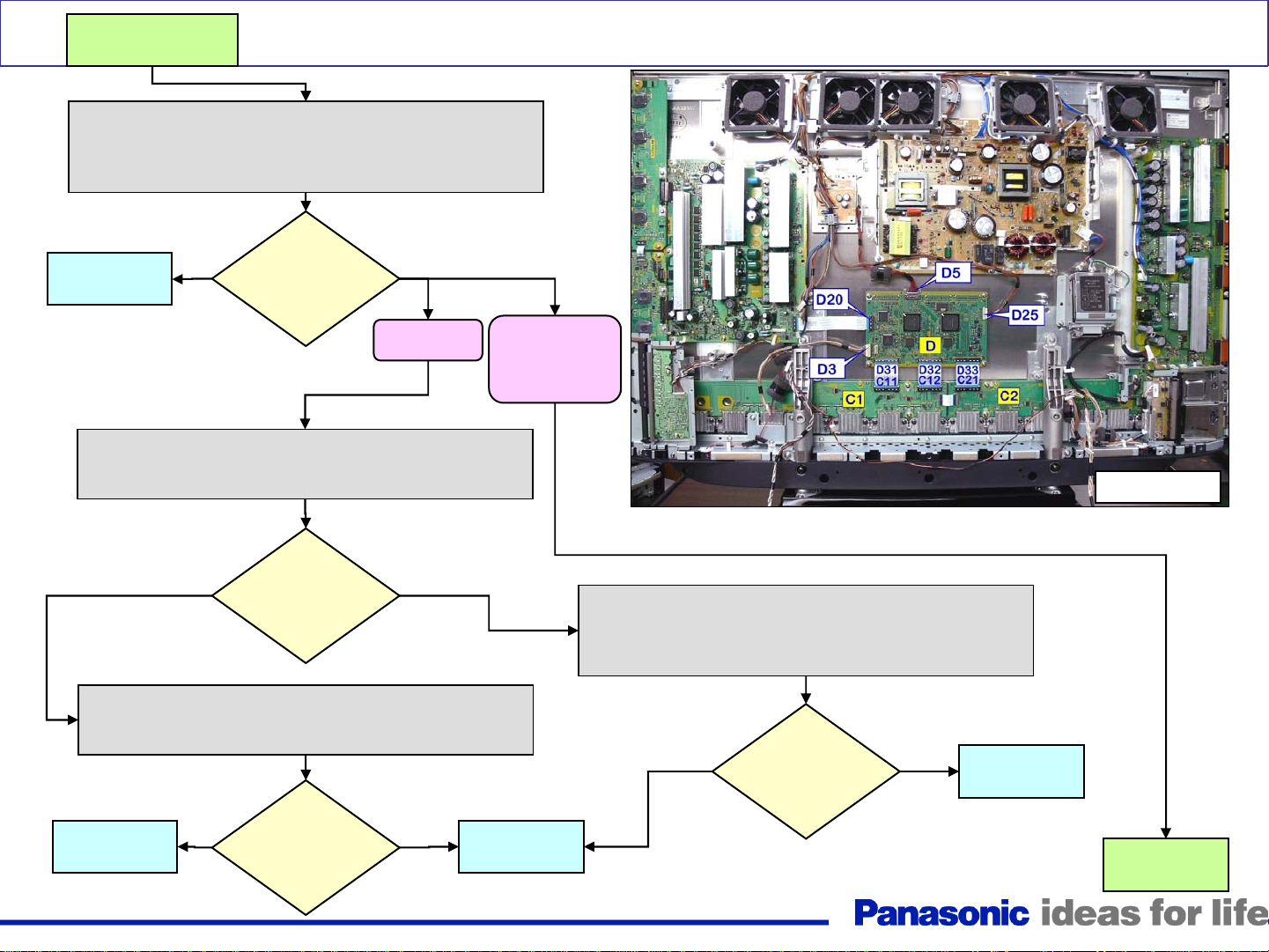
Continue from the
previous slide (A)
Reconnect SS33 and disconnect D31, D32, and D33 on the
D board (To get to this connectors, remove the A Board
Block Assembly). Measure the resistance between pin 5 of
connector P25 on the P board and ground (Chassis).
LED blinks 5 times
Yes No
Replace
the D board
Reconnect D31 and D32 only. Measure the resistance
between pin 5 of connector P25 on the P board and
Yes
Disconnect the Flex cables between the panel and the C1
board (CB1~CB8). Measure the resistance between pin 5
of connector P25 on the P board and ground (Chassis).
Yes
Replace
the C1 board
Is there a
short to
ground?
ground (Chassis).
Is there a
short to
ground?
Is there a
short to
ground?
TH-42PZ80/85U
No
No
TH-46PZ80/85U
TH-50PZ80/85U
TH-46PZ800/850U
TH-50PZ800/850U
Replace
the Panel
Figure 5
Reconnect D33 and disconnect the Flex cables between
the panel and the C2 board (CB9~CB15). Measure the
resistance between pin 5 of connector P25 on the P
board and ground (Chassis).
No
Is there a
short to
ground?
Yes
Replace
the C2 board
TH-42PZ85U
Go to the
next slide (B)
17
Page 18
Reconnect D31 only. Measure the resistance between pin
Disconnect the Flex
cables between the
panel and the C1 board
(CB1~CB6). Measure
the resistance between
pin 5 of connector P25
on the P board and
ground (Chassis).
LED blinks 5 times
5 of connector P25 on the P board and ground (Chassis).
Yes
Is there a
short to
ground?
No
Continue from the
previous slide (B)
Reconnect D32 and D33 and disconnect C26 on the C2
board. Also disconnect the Flex cables between the panel
and the C2 board (CB7~CB11). Measure the resistance
between pin 5 of connector P25 on the P board and
ground (Chassis).
Replace
the C1 board
Yes
Is there a
short to
ground?
No
Replace
the Panel
Replace
the C3 board
Yes
Is there a
short to
ground?
18
Yes No
Replace
the C2 board
Reconnect C26 and the Flex-cables between the panel
and the C2 board. Disconnect the Flex cables between
the panel and the C3 board (CB12~CB15). Measure the
resistance between pin 5 of connector P25 on the P
board and ground (Chassis).
Is there a
short to
ground?
No
Replace
the Panel
Page 19

LED blinks 6 times
Trouble Mode
SC Energy Recovery SOS
Replace
the SC board
Defective Board (Possibility)
SC, P Board (SC >D> P )
Disconnect
connectors SC2, and SC20
from the SC board. Plug in
the TV and turn it on.
Yes No
Does the
TV power
up and
stay on?
Warning: Disconnect AC Power prior to making any
disconnection or connection
(*2) CAUTION: Before connecting P2/SC2 or
P11/SS11, discharg e is ne ce ssary to prev e nt
potential shock caused by VSUS.
Connect SC2 (*2) and
SC20. Plug in the TV
and turn it on.
Clean and reseat the ribbon
cables between the D and the C
boards. Also reseat the cables
between the C boards. If
problem persists, replace the D
board
Yes
Does the P
board output
15V at pin 1 of
P7 and Vsus at
pin 1 of CN P2
before the TV
shuts down?
19
No
Replace
the P board
Page 20

SU/SD Board Isolation Procedure
Unlike previous models of Panasonic Plasma TVs, the 2008 models are designed not to turn-on if either of the SU and
SD boards is disconnected. Disconnecting either causes the unit to shutdown and the power LED to bli nk 7 times.
Procedure to isolate the SU/SD board
For SU board: Disconnect connectors SC41/SU41, SU11/SD11.
For SD board:
SU11/SD11.
Isolating the SU/SD board does not require the removal of its mounting
screws.
Place a jumper between “VF Ground” (labeled H.V. DANGER) on the SU
board or SD board and coil L801 on the SC board, see figure 6 and 7.
The jumper can be connected to the floating grou nd screws on the SU
board, which are located above and below connector SU41, see figure 2.
Caution: Before turning the unit on, confirm that the jumper is not
connected to a chassis ground screw, as this will cause s evere damage
to the unit. Confirm proper connection by measuring continuity
between floating ground and chassis ground. The resistance should be
in the kilo-ohms range.
Disconnect connectors SC42/SD42, SC46/SD46, and
Figure 6
Figure 7
20
Page 21

LED blinks 7 times
Trouble Mode
SC Floating voltage SOS
Make sure connectors P2/SC2, SC20/D20 are
not loose and are seated properly.
Reconnect the SD board only.
(See instructions on previous slide).
Plug in the TV and turn it on.
Does the
TV shut down
and the power
LED
blink 7 times?
Replace the SU
board.
Note: The panel can
possibly cause the SU
board to become
damaged
Defective Board (possibility)
SC, SU, SD, D, P board (SC,SU,SD>P)
YesNo
Disconnect the SD board and
reconnect the SU board. (See
instructions on previous slide).
Plug in the TV and turn it on.
No
Does the
TV shut down
and the power
LED
blink 7 times?
Physically disconnect the SU board and the
SD board. (See instructions on previous
slide). Plug in the TV a nd turn it on.
Yes
Replace the SC board.
With the SU board and the SD board
still disconnected, remove connectors
SC2 and SC20 from the SC board.
Plug in the TV and turn it on.
No
Does the
TV shut down
and the power
LED
blink 7 times?
Replace the D board.
Yes
Replace the SD board.
Note: The panel can
possibly cause the SD
board to become damaged
Does the
TV shut down
and the power
LED
blink 7 times?
YesNo
Replace the SD, and SU
board.
Note: The panel can possibly
cause the SD and SU boards
to become damaged
21
Page 22

D16280 (D280) Location
N 2.7V SOS
To pin 66
IC9003
PANEL
Note: The location for this component may not be the same for all models
TH-42PZ85U
Figure 8
Anode
D16280
(D280)
Figure 9
Figure 10
22
Page 23

LED blinks 8 times
Trouble Mode
SS Energy recovery SOS/Panel
Disconnect the TV. Use a volt-meter and place the positive
probe on the anode of D280 on the SS board (See previous
slide for location), while the negative probe is grounded. Plug
in the TV and turn it on
Defective Board (possibility)
SS, D board (SS>,D)/PDP
Disconnect
connector SS33 from the
SS board. Plug in the TV
and turn it on
Yes
Does the
TV power
up and
stay on?
Warning: Disconnect AC Power prior to making any
disconnection or connection
No
Replace
the D board
Replace
the panel
Yes
Is there
approx. 2.7V
at the anode
of D280 on
the SS
board?
23
No
Replace
the SS board
Page 24

LED blinks 9 times
Trouble Mode
Panel Status
Defective Board
D Board
Replace the D board.
Warning: Disconnect AC Power prior to making any
disconnection or connection
24
Page 25

The power LED blinks 10 times at plug-in
Trouble Mode
Dead/No power
Defective Board (Possibility)
P, A, GS, K, GH
Sub-Voltages Distribution Diagram
10 blinks condition can be caused by:
• Missing/Shorted F_STB_15V
• Missing/Shorted SUB9V, SUB5V, and SUB3.3V
• Wrong diagnostic by the A board
A board Connectors Location
Figure 11 Figure 12
25
Page 26

The power LED blinks 10 times at plug-in
Trouble Mode
Dead/No power
Warning: Disconnect AC Power prior to making any
disconnection or connection
Unplug the TV. Using a voltmeter, place the positive
probe at pin 6 of connector P7 while the negative probe is
Defective Board (Possibility)
P, A, GS, K, GH
grounded. Plug in the TV
Unplug the TV and
disconnect connector A1 on
the A board. Plug in the TV
NOTE: When taking voltage reading, place your meter’s probe on the test point or pin
indicated before connecting the TV to the AC line. The voltage you intent to measure
may only appear for a brief moment.
NO
NO
seconds when the TV is plugged
Is there 3.2V
present for a couple of
into the AC
line?
Do the AC relays
click after the TV is plugged
into the AC line?
Yes
Replace
The P board
Yes
Replace
The A board
NO
Do the AC relays
click after the TV is plugged
into the AC line?
Yes
If cable between connectors K1
and A1 is OK, Replace the K board.
26
Go to the
Next slide
Page 27

The power LED blinks 10 times at plug-in
NOTE: When taking voltage reading, place your meter’s probe
on the test point or pin indicated before connecting the TV to the
AC line. The voltage you intent to measure may only appear for
a brief moment.
Warning: Disconnect AC Power prior to making any
disconnection or connection
Unplug the TV and disconnect
connector P6 on the P board. Using a voltmeter,
place the positive probe at pin 7 of connector P6
while the negative probe is grounded. Plug in the TV
No
Replace
The P board
Is there 15V
present when the TV
is plugged into the
AC line?
Yes
Replace
The A board
No
pin 7 of connector P6/A6 when
the TV is plugged into
Is
there 15V at
the AC line?
Unplug the TV. Reconnect
connector A1 only.
Plug in the TV
No
Does the
power LED
blink 10 times?
Yes
Yes
Continue from the
previous slide
Unplug the TV. Disconnect
connectors A1, GS52, and
GH11 on the A board.
Plug in the TV
No
Does the
power LED
still blink
10 times?
Yes
Replace
The A board
Replace the
GH board.
No
Does the
power LED
blink 10 times?
Unplug the TV.
Reconnect
connector A52 and
leave connector GH11
disconnected.
Plug in the TV
Yes
Replace the
GS board.
27
Replace
the K board.
Page 28

LED blinks 10 times after pressing the power button
Trouble Mode
SUB 5V SOS, Main 3.3V SOS
DTV 9V SOS, Tuner Power SOS
Disconnect connectors SC2 and SC20 on the
Scan (SC) board. Plug in the TV and turn it on.
No Yes
Replace
The SC board
Does the unit shut
down and the
power LED blinks
10 times?
Unplug the TV and re-connect CN SS11 (*2),
SS33 and CN SS34 on the SS board and CN
P12 on the P board. Measure Vsus (*3) at pin
1 of CN P11 and Vda (Approx. 75V) at pin 1 of
CN P12. Plug in the TV and turn it on.
Defective Board
P, A, SC,SS, GS, G Board
Unplug the TV and re-connect CN SC2(*2), and SC20
on the SC board. Disconnect CN SS11(*2), SS33, and
SS34 (*4) on the SS board and CN P12 of the P board.
Install the jumper from SS34 between pin 8 and 10 of
CN P12. Plug in the TV and turn it on.
No
Warning: Disconnect AC Power prior to making any
disconnection or connection
(*2) CAUTION: Before connecting P2/SC2 or
P11/SS11, discharg e is ne ce ssary to prev e nt
potential shock caused by VSUS.
(*3) VSUS about 180V (Accurate voltage is provided
on the Panel Label)
(*4) Place a jumper across pin 8 and 10 of connector
P12. The unit will not enter the standby mode without
the jumper.
Does the power
LED stay on
when the TV is
turned on?
Yes
Replace
The SS board
Note: CN = Connector
Replace
The A board
Are
any of these
voltages
missing?
28
YesNo
Replace
The P board
Page 29

LED blinks 11 times
Trouble Mode
Fan SOS
Defective Board (Possibility)
Fans, PB, A Board
Fan SOS Circuit
Warning: Disconnect AC Power prior to making any
disconnection or connection
11 blinks condition happens:
1. If one of the fans opens or
increases resistance.
2. If the PB board becomes
defective triggering
shutdown.
3. If the CPU in the A board
gives a wrong diagnostic
triggering shutdown
Figure 13
29
Page 30

LED blinks 11 times
Trouble Mode
Fan SOS
Unplug the TV and disconnect
connector PB30 on the PB board.
Plug in the TV and turn it on.
Defective Board (Possibility)
Fans, PB, A Board
Unplug the TV and disconnect the
fans, one at a time. (See caution
(*5)). Plug in the TV and turn it on.
No
Does the power
LED stay on
when the TV is
turned on?
Warning: Disconnect AC Power prior to
making any disconnection or connection
Caution (*5) When a fans is disconnected,
place a jumper between pins 2 and 3 of the
connector that the fan was removed from.
Yes
Replace
the Fan.
Replace
The A board
No
Does the TV
stay on for
more than 30
seconds
when the TV
is turned on?
30
Yes
Replace
The PB board
Page 31

LED blinks 12 times
Trouble Mode
Sound SOS
Unplug the TV and disconnect
connectors P6 and P7 on the P
board. Plug in the TV
Defective Board (Possibility)
Speakers, A Board
Unplug the TV and disconnect the
Left and Right speakers connectors.
Plug in the TV and turn it on
No
Does the power
LED stay on
when the TV is
turned on?
Warning: Disconnect AC Power prior to making any
disconnection or connection
Yes
Check the speakers and
the speaker’s wires.
Check P15V (Pin 1 of P6) and
follow 2 blinks instructions
No Yes
Is the TV turning on by
itself at plug in with:
Power LED = Off.
LED on SS board = On.
LED on SC board = On
31
Replace
The A board
Page 32

LED blinks 13 times
Trouble Mode
Communication error with IC8001
TH-42PZ80/85/800U
TH-46PZ80/85/800U
TH-50PZ80/85/800U
Disconnect A52 on the A
Board (See Figure 1). Plug
in the TV and turn it on
No Yes
Replace the GS
board
Is the power
LED still
blinking?
Unplug the TV and disconnect
connectors P6 and P7 on the P Board
(See Figure 1). Plug in the TV.
Defective Board
A Board
TH-46PZ850U
TH-50PZ850U
Disconnect A9 on the A
Board. Plug in the TV
and turn it on
Warning: Disconnect AC Power prior to making any
disconnection or connection
A board Connectors Location
Replace the D
board
No
Is the TV turning on by
itself with the following
conditions?
Power LED = Off
SC LED= On
SS LED = ON
Figure 14
Yes
Replace the A
board
32
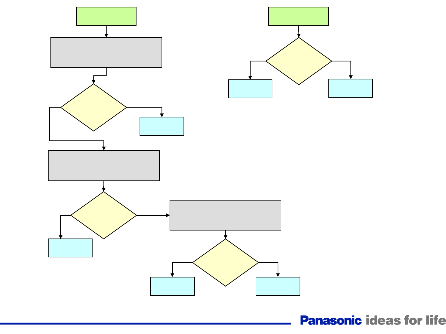
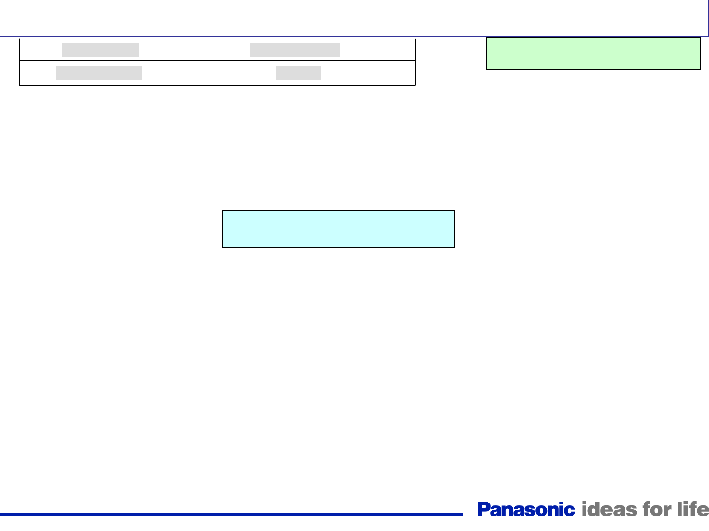
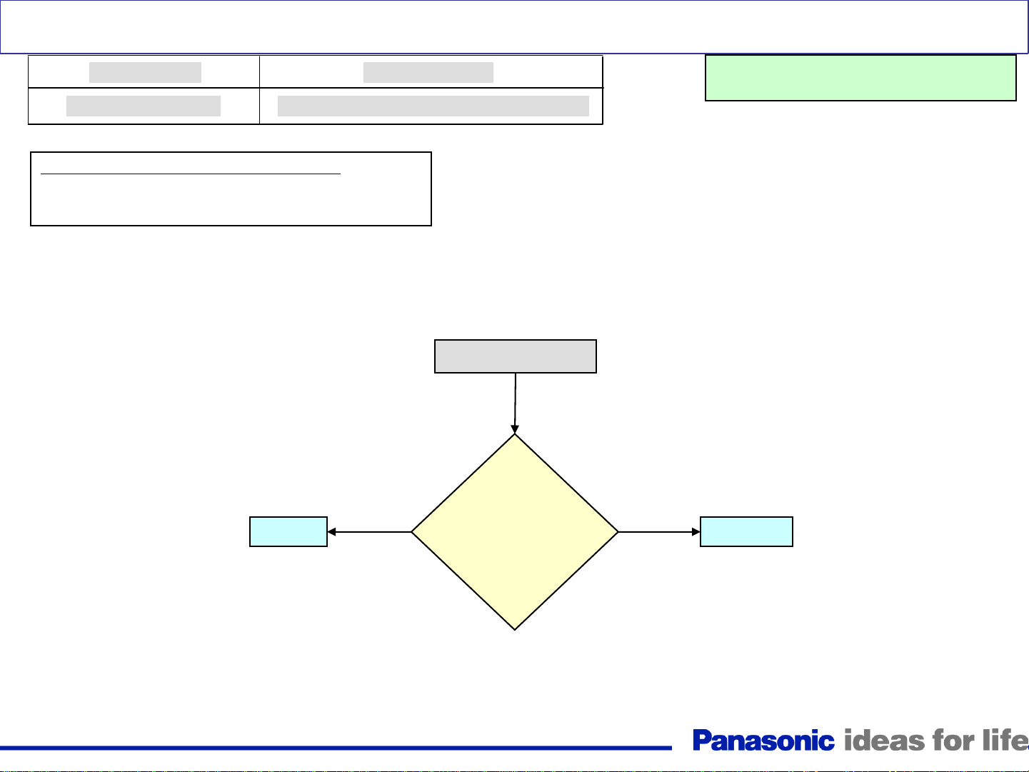
Page 33

Trouble Mode
Dead/No power
No Power/Dead Unit
Defective Board (Possibility)
P, A, GS, K
Warning: Disconnect AC
Power prior to maki ng any
disconnection or connection
Yes
Is there 5V present
when the TV is plugged into
the AC line?
Yes
Disconnect connector A7. Place your
volt-meter on pin 5 of connector P7.
Is there continuity
between pins 8 and
10 of connector
P12 of the P
board?
Plug in the TV and turn it on.
Yes
NO
Unplug the TV and place your
volt-meter on pin 5 of
connector P7. Plug in the TV.
NO
Unplug the TV
NO
Is there 5V when the
TV is plugged in?
NO
Check connection
between P12 and
SS12. Also check for
missing jumper on
SS34 on the SS board.
If jumper on connector
SS34 is present,
replace the SS board.
NO
Yes
Do the AC relays
click after the TV is plugged
into the AC line?
Place your volt-meter on
pin 9 of connector A1.
Press the power switch
Does
pin 9 of connector
A1 go from 4.5V to 0V while the
power button on the TV is
pressed?
Yes
Unplug the TV and place your volt-meter
on pin 11 of connector P25 or A25. Plug
in the TV and press the power switch
NO
Is there 3.2V
present when
the power
button is
pressed?
Yes
Yes
Go to the
Next slide
Replace
The P board
Replace
The A board
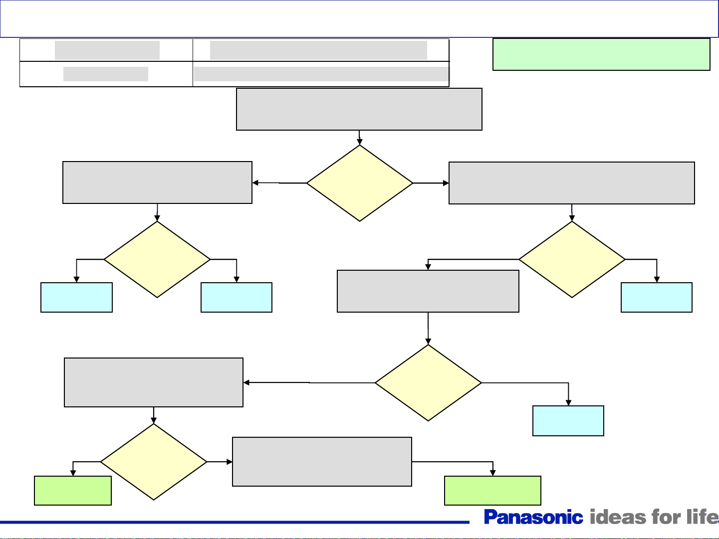
If wiring connections
are ok, check
the S & K boards.
33
Replace
The A board
Replace
The P board
Page 34

Continue from
Previous slide
No Power/Dead Unit (Continue)
Unplug the TV and place your
volt-meter on pin 6 of
connector P7. Plug in the TV.
NO
TH-42PZ80/85U
TH-46PZ80/85U
TH-50PZ80/85U
TH-42PZ800U
TH-46PZ800U
TH-50PZ800U
TH-46PZ850U
TH-50PZ850U
NO Yes
Replace
The A board
Do the AC
relays click after
the TV is plugged into
the AC line?
Reconnect A1 and
disconnect connector
A52. Plug in the TV.
Reconnect A1 and
disconnect connector
A9. Plug in the TV.
Do the AC
relays click after
the TV is plugged into
the AC line?
Unplug the TV and
disconnect
connector A1. Plug in
the TV.
Yes
Replace
The G board
Is
NO Yes
there 3.2Vor 2.7V at
pin 6 of connector P7 when the
TV is plugged into
the AC line?
If the cable between connectors K1
and A1 is OK, Replace the K board.
If the cable between connectors GS09
and A9 is OK, Replace the GS board.
Replace
The A board
Reconnect A52 and
disconnect connector
A51. Plug in the TV.
Reconnect A9 and
disconnect connector
TH-42PZ80/85U
TH-46PZ80/85U
TH-50PZ80/85U
TH-42PZ800U
TH-46PZ800U
TH-50PZ800U
TH-46PZ850U
TH-50PZ850U
A51. Plug in the TV.
Replace
The P board
Do the AC
NO
relays click after
the TV is plugged into
the AC line?
If the cable between connectors GS52
and A52 is OK, Replace the GS board.
TH-42PZ800U
TH-46PZ800/850U
TH-50PZ800/850U
Yes
TH-42PZ80/85U
TH-46PZ80/85U
TH-50PZ80/85U
34
Page 35

No Sound
Warning: Disconnect AC Power prior to making any
disconnection or connection
Check the cable
between connector
A7 on the A board
and P6 on the P
board.
No
Is there 15V at
pin 1 of CN A6
on the A
board?
Yes
Yes
Is there a sound
waveform at pin 1
and 3 of CN A12
on the A board?
No
Check the speakers.
(Make sure A12 is
properly seated).
35
Replace
The A board
Page 36

This page is purposely left blank.
36
Page 37

Troubleshooting for Picture Problems
37
Page 38

Diagnostic Method for Troubleshooting PDP Television
<Introduction>
1. There are two kinds of picture problem
1) Abnormal picture
2) No picture
2. Basic concept of determining the defective board
1) Which area is the symptom displayed on the screen?
A. Part of the screen
B. All over the screen
3. Adjustment after PCB exchange
1) After exchanging the following boards, voltage adjustment is required.
P board, SC board, SS board => Please refer to “Service Manual”.
38
Page 39

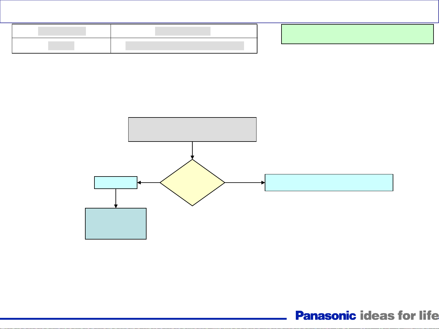
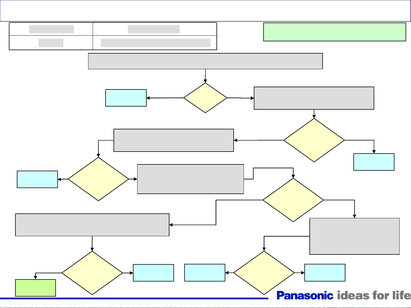
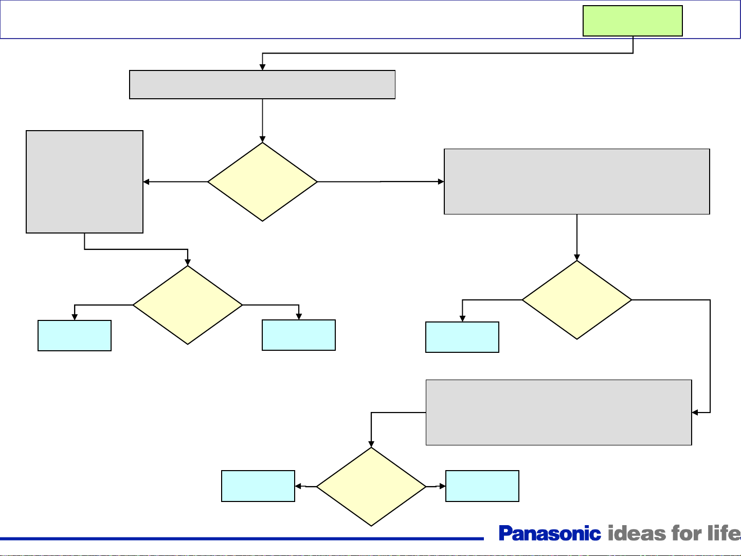
Troubleshooting for Picture Trouble
<How to determine the defective board>
Start
Some part of the screen
Where is
the symptom
displayed?
Upper or Lower half
(from front view)
Left or Right half
(from front view)
Upper half
Lower half
Both area
Right half
Left half
SU Board (or D, or SC)
SD Board (or D, or SC)
SC Board (or D)
D Board (or C1, or Panel)
D Board (or C2, or Panel)
*Note :Panel gas leakage
Because of a very small crack in the
panel, gas leakage will start.
In this picture, gas leakage started at
the left top corner.
Finally, gas leakage will lead to the
symptom “No picture with buzz
noise”.
39
Page 40

Diagnosis for Picture Problem (All Over the Screen)
<Symptom>
Abnormal Color, Vertical Line, Sync Error, Noise Picture
<Sample Picture>
<Possible Cause>
D Board, SC Board, SU Board, SD Board
<Block Diagram>
e.g. TH-42PZ80U
IC1100
PROCESSOR
IC4510
MICRO
A
IC9500
PICTURE
OUTPUT
IC9900
PLASMA AI
<Model>
All Models
SC SS
SU
SD
<Back side view>
Buffer IC Buffer IC
HDMI I/F
Peaks
Lite
IC8001
LVDS
LVDS
RECEIVER
DISCHARGE
CONTROL
S.F. PROCESSOR
Scan Control Pulse
Sustain Control Pulse
40
DATA
DRIVER
Video DATA (R)
Video DATA (L)
Page 41

Diagnosis for Picture Problem (All Over the Screen)
<Diagnosis (2)>
Confirm the waveform at “TPSC1” of the SC board
<Result>
Waveform OK
Correct Waveform
<Cause>
D Board defect
D
Video/Panel
Control
PLASMA AI
IC9300
IC9400
IC9500
DISCHARGE
CONTROL
<Result>
Waveform NG
<Cause>
TPSC1
SC SS
Sample of NG Waveform
Here
SC,SU,SD Board defect
Refer to “Diagnosis (3)”
on next page
SU
<Back side view>
SD
Buffer IC Buffer IC
DATA
DRIVER
Scan Control Pulse
Sustain Control Pulse
41
Video DATA (R)
Panel Drive Circuit
Video DATA (L)
Page 42

Diagnosis for Picture Problem (All Over the Screen)
<Diagnosis (3)>
Confirm the waveform at “TPSC1” after removing the SU or SD Board from the SC Board
<Result>
Situation
Disconnect SU Board
(Connect SD)
Disconnect SD Board
(Connect SU)
Disconnect the SU
and SD Boards
Correct Waveform
Condition
Condition 2
Bottom half of
Waveform OK?
Picture OK?
Upper half of
Waveform OK? SD Board
Picture OK?
Screen should
Waveform OK? SC Board
be black
SC SS
TPSC1
SU
<Back side view>
SD
Cause
SU Board
42
Buffer IC Buffer IC
Page 43

Diagnosis of Vertical Line Problem
NG Area (Front view)
Panel
case1
IC IC IC IC
Buffer IC Buffer IC
C2
C1
C1
Buffer
case2
Drive
IC(2)
inside
case1 case2
Thin vertical line
or 1 block not lighting
PDP panel (Driver IC) NG
D board (or C board) NG
( or D board, or C board )
1 Line
Buffer
1 Block 2 Blocks
PDP PanelPDP Panel
D-board ( or C-board)
Driver IC
C Board
Driver IC Driver IC Driver IC
FPC
A number of blocks
not lighting
FPC
C Board
Buffer
43
Buffer
or
D boardD Board
Page 44

Picture Trouble at Upper or Lower half
<Symptom>
No Picture, Picture noise, Full Horizontal line, etc.
<Models>
42 inch (HD Panel)
<NG Area>
(Front view)
1
SS
2
SU
SC
SD
D
<Actual Symptom>
Symptom
Result
Symptom
Result
: Horizontal line (Lower side)
: SD board
: Horizontal line (Upper side)
: D board
C1C2
<Defective board>
Trouble at Upper half : SU-board (SC or D) defect
1
Trouble at Lower half : SD-board (SC or D) defect
2
Full Horizontal line at both area : SS-board (D) defect
(*)
44
Symptom
Result
: Horizontal line (Both area)
: SS board
Page 45

Picture Trouble at Right or Left half (50 Inch)
<Symptom>
<Symptom>
<Actual Symptom>
No Picture, Picture noise, etc.
<Models>
50inch (HD Panel)
<NG Area>
(Front view)
SS2
SS
SS3
2
1
SU
SD
SC
D
Symptom
Result
: Cyan noise (Right side)
: D board
C3
C2
C1
<Defective board>
Trouble at Right half : D-board defect
1
Trouble at Left half : D-board defect
2
45
Page 46

Picture Trouble at Right or Left half (42 Inch)
<Symptom>
<Symptom>
<Actual Symptom>
No Picture, Picture noise, Full Vertical line, etc.
42 inch (HD Panel)
<NG Area>
(Front view)
SU
SS
12
SD
SC
C1C2
D
Symptom
Result
: Vertical line
: Panel
<Defective board>
Trouble at Right half : D or C1 board (Panel) defect
1
Trouble at Left half : D or C2 board (Panel) defect
2
46
Page 47

Picture Trouble in 50 Inch Models
<Symptom>
<Symptom>
No Picture, Picture noise, Half Vertical line, etc.
<Models>
50inch (HD Panel)
<NG Area>
(Front view)
SS2
SU
SS
3
12
SC
D
<Defective board>
Trouble at Upper right :
1
C1 board or Panel defect
Trouble at Upper middle :
2
C2 board or Panel defect
SS3
C3
C2
C1
SD
47
Trouble at Upper left :
3
C3 board or Panel defect
Page 48

<Symptom>
<Symptom>
Picture Trouble all Over the Screen
<Actual Symptom>
Picture noise, Full Vertical line, etc.
<Models>
42inch (HD Panel)
<NG Area
(e.g. 42 inch Panel)>
(Front view)
SS
1
C1C2
SU
SD
SC
D
Symptom
Result
Symptom
Result
Symptom
Result
: Vertical line (All over screen)
: D board
: White balance NG
: D board
: Abnormal Picture
: SC board
<Defective board>
Trouble at All area : D or SC board
1
(SU,SD) defect
48
Page 49

Examples of Symptoms and Remedies
49
Page 50

Picture Problem (All over the screen)
<Symptom> Noise Picture
<Photo of Symptom>
Model : 42 inch Result : A Board Model : 42 inch
Result : D Board
Model : 42 inch
Result : D Board
Model : 42 inch
Result : A Board
Model : 42 inch
Result : SC Board
Model : 42 inch
Result : SC Board
Model : 42 inch
Result : SC Board
50
Model : 42 inch
Result : SC Board
Model : 42 inch
Result : SC Board
Page 51

Picture Problem (All over the screen)
<Symptom> Vertical Line
<Photo of Symptom>
Model : 42 inch
Result : D Board
Model : 42 inch
Result :D Board
Model : 42 inch Result : D Board
Model : 42 inch
Result : D Board
Model : 42 inch
Result : SC Board
Model : 42 inch
Result : D Board
Model : 42 inch
Result : SD Board
51
Model : 42 inch
Result : D Board
Model : 42 inch
Result : SD Board
Page 52

Picture Problem (All over the screen)
<Symptom> Abnormal Color, White Balance NG
<Photo of Symptom>
Model : 42 inch
Result : D Board
Model : 42 inch
Result : D Board
Model : 42 inch
Result : D Board
MagentaMagentaYellow
Model : 42 inch
Result : D Board
Model : 42 inch
Result : D Board
Model : 42inch
Result : D Board
Model : 42 inch
Result : D Board
Blue Abnormal ColorGreen
Model : 42 inch
Result : D Board
CyanRedRed
Model : 42 inch
Result : D Board
52
Page 53

Picture Problem (All over the screen)
<Symptom> Sync Error
<Photo of Symptom>
Model : 42 inch
Result : D Board
Model : 42 inch
Result : D Board
Model : 42 inch
Result : D Board
Model : 42 inch
Result : D Board
Model : 42 inch
Result : D Board
Model : 42 inch
Result : D Board
Model : 42 inch
Result : D Board
Model : 42 inch
Result : D Board
53
Page 54

Picture Problem (Right half or Left half)
<Symptom> Vertical Line
<Photo of Symptom>
Model : 50 inch
Result : D Board
Model : 42 inch
Result : D Board
Model : 42 inch
Result : D Board
Model : 42 inch
Result : D Board
Model : 42 inch
Result : D Board
Model : 42 inch
Result : D Board
Model : 42 inch
Result : D Board
Model : 42 inch
Result : D Board
54
Page 55

Picture Problem (Upper or Bottom)
<Symptom> Vertical Line
<Photo of Symptom>
Model : 42 inch
Result : D Board
Model : 42 inch
Result : D Board
Model : 42 inch Result : D Board
Model : 42 inch
Result : SU Board
Model : 42 inch
Result : SS Board
Model : 42 inch
Result : D Board
Model : 42 inch
Result : SU Board
55
Model : 42 inch
Result : SC Board
Page 56

Self-check Procedure
CHASSIS: GPH11D
All models
How to access the self-check
screen to reset the unit.
Select a television channel, and while
pressing the [VOLUME ( - )] button on
the main unit, press the [OK] button on
the remote control for more than 3
seconds.
How to Exit the self-check
screen
Press and hold the Power button on
the TV for 5 seconds or disconnect the
AC cord from the wall outlet.
NOTE: This procedure does
not reset the TV
Self-check Screen
TV volume down & OK on remote only does a basic IC self check. It does NOT Reset the TV.
It does not clear channel programmed settings, picture settings, channel labels, LOCK mode settings, or password.
Using this method, it shows the unit firmware version (Peaks 1.050 and GenX 1.00) and it checks IC communications ONLY.
This is more useful to identify the firmware version without having to decode the info in the setup menu About/Version screen.
56
Page 57

Reset Procedure
CHASSIS: GPH11D
All models
To Reset the Unit, turn the TV on and while pressing the “VOLUME ( - )” button on
the main unit, press the “Menu” button on the remote control for more than 3 seconds.
The Self-Check menu appears on screen. Then, disconnect the AC cord from the wall
outlet.
Note: All customer programmed parameters will be erased.
57
 Loading...