

Page 1

Technical Guide
Technical Guide
Model : TH--
Model : TH
TH--
TH
(GPF9D and
(GPF9D and
Troubleshooting Handbook
Troubleshooting Handbook
103PF9UK
103PF9UK
103PF10UK
103PF10UK
103””
103
GPF10D
GPF10D
Plasma
Plasma
Chassis)
Chassis)
Panasonic Services Company
National Training
Page 2
This page is purposely left blank.
2
Page 3
Table of Contents
Subject Page
Introduction 4
AC Power Requirement 5
Rear Cover Removal 6
Chassis Structure 7
Chassis Layout 8
Board Description 9
Troubleshooting Display (Distortion) Problem 10-18
Relation of Board and Display Area 11
Troubleshooting for No Power 19-21
Shutdown (SOS) Troubleshooting 22-46
List of LED Blink Codes 23
Power LED blinks 1 time 24
Power LED blinks 2 times (SS Side) 25
Power LED blinks 2 times (SC Side) 26
Power LED blinks 3 times 27
Subject Page
Power LED blinks 8 times 42
Power LED blinks 9 times 43
Power LED blinks 10 times 44
Power LED blinks 11 times 45
Power LED blinks 13 times 46
Alignment (Adjustment) Procedure
Self-check Procedure
How to reset the unit
How to enter the CAT (Computer Aided Test) Mode
How to enter the IIC mode
How to access the pattern generator
How to enter the CD Mode
How to enter the MS Mode
47-53
54
55
56
57
58
59
60
Power LED blinks 4 times 28
Power LED blinks 5 times 29-34
Power LED blinks 6 times 35-36
Power LED blinks 7 times 37– 41
3
Page 4
Introduction
<Introduction>
1. Basic concept of how to determine the defective board
1) Verification of voltages
Normally, when there is a power problem, shutdown occurs immediately.
So, to resolve a power problem, voltage checks are necessary before shutdown.
2) Check if the power comes up after disconnecting the board under suspicion.
If power comes up (*) after disconnecting a board, the board is defective.
(*) “Power comes up” equals “no shutdown”.
2. Troubleshooting Video and Audio problems
3. Examples of video problems
4. Troubleshooting shutdown problems
5. Adjustment after PCB exchange
1) After exchanging the following boards, voltage adjustment is required.
P board, SC board, SS board => Please refer to the “Service Manual”.
4
Page 5
AC Power Requirement
Note
1)
Caution!
1)
Caution!
This PDP uses a 240V source and consumes 1,500W of power .
This PDP uses a 240V source and consumes 1,500W of power .
Check the customer’’
Check the customer
2)Maintenance space!
2)Maintenance space!
A minimum space of 700mm is needed at the rear of the unit
A minimum space of 700mm is needed at the rear of the unit
for installation.
for installation.
3)Please check
3)Please check
maintenance contract.
maintenance contract.
with the Sales company
with the Sales company
s AC power source.
s AC power source.
for the service and
for the service and
5
Page 6
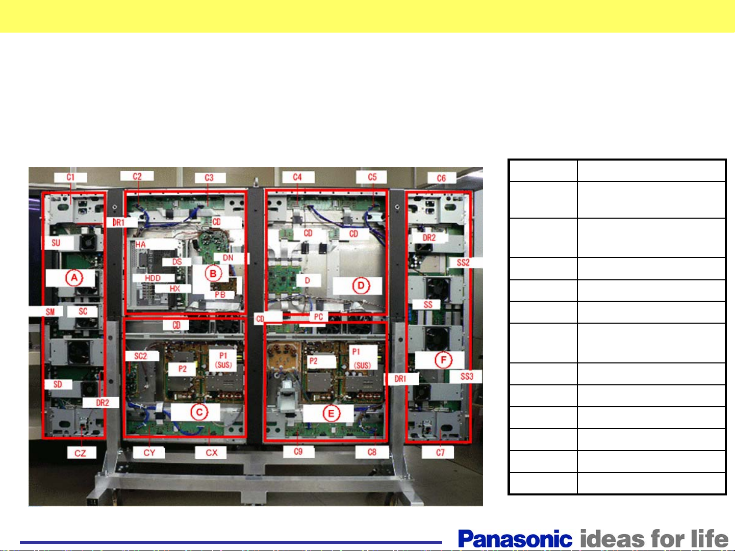
Back Covers
The unit contains 6 back covers that provide access to
different areas of the board assembly.
Zone Board
A
B PB, DS, HX, HA, DN,
D D, CD×2, C4
C P, CX
E P, F, C9
F SS, SS2, SS3, DR1/2
B+C FAN, CD
D+E FAN, CD, PC
A+B C2
D+F C5
A+C CY, SC2
E+F C8
SC, DR1/2,,SU, SM, SD
C1, CZ, FAN
HDD, CD, C3
C6, C7, FAN
6
Page 7
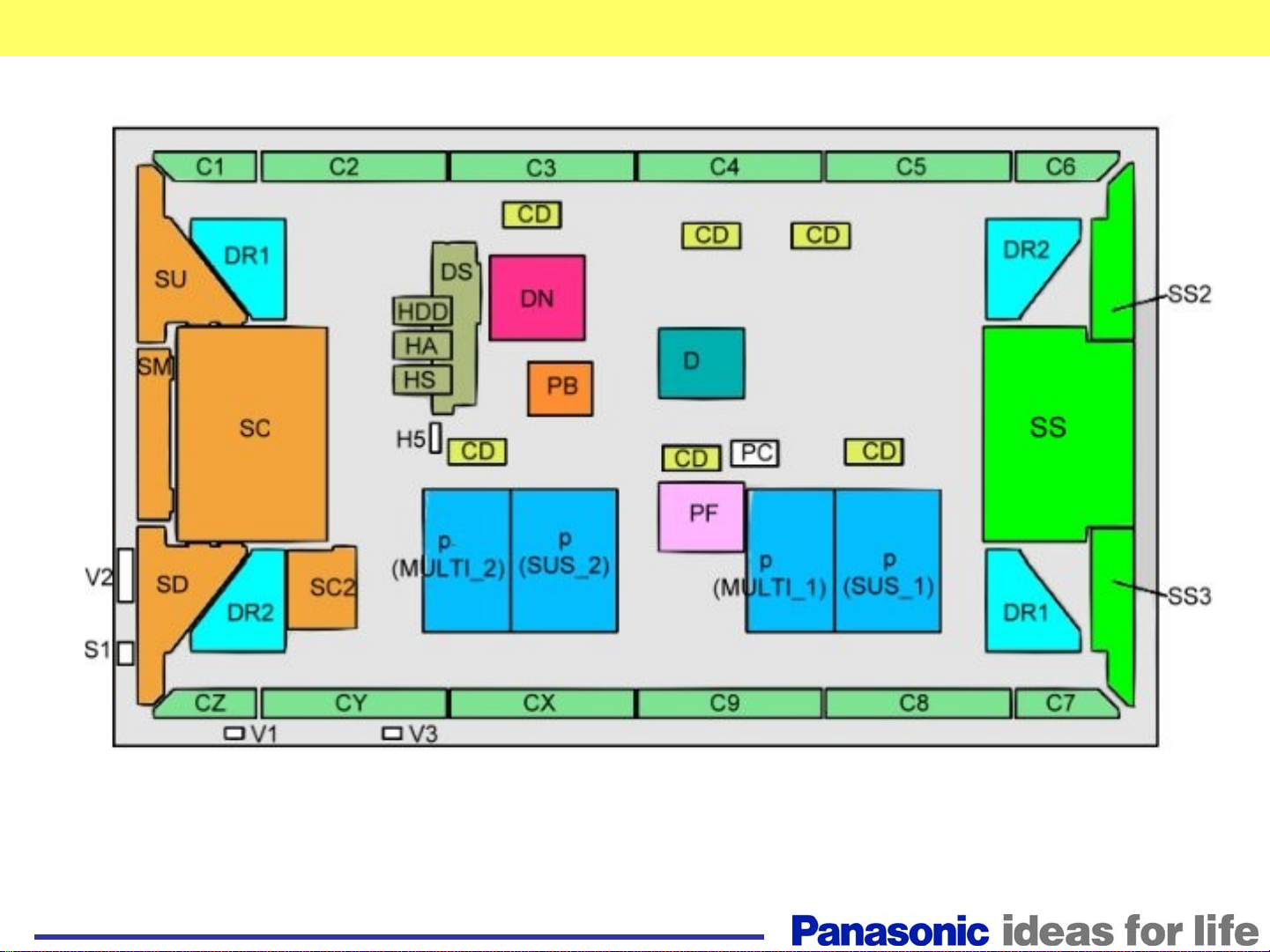
Chassis structure
C1 C2 C3
DR1 DR2
SU
HA
HX
HDD
SM
SC
SD
DR2
C4
CD CD CD
DS
P1・P2 P1・P2
DN D
CDCDCD
C5
DR1
C6
SS2
SS
SS3
CZ
C9CXCY
C8
C7
The 103” plasma display television contains many more boards than the smaller size
plasma display models that are on the market today. It contains:
1. Two P boards (power supply)
2. Twelve C boards (data drive)
3. The SM board is added to complement the SU and SD of current model.
4. There are four DR boards added to the unit, one at each corner
5. There is the DS board that connects the HX, HA, and HDD to the DN board.
7
Page 8
Chassis Layout
8
Page 9
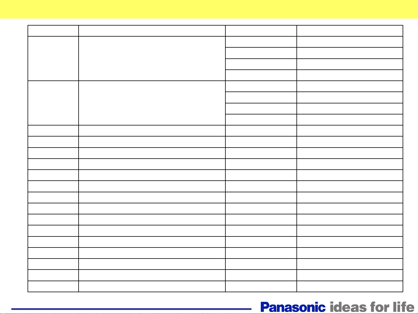
Board Description
Board Name Function Board Name Function
D Digital Signal Processor, Format Converter, Plasma
AI Processor Sub-Field Processor
DS Slot Interface (Audio / Video / Sync Input Switch),
SYNC Processor, Audio Processor, Speaker Out
Amplifier, DC-DC Converter
SS Sustain Drive V2 Key Scan
SC Scan Drive V3 Remote control Receiver
SC2 DC-DC Converter For Scan Drive PB Fan Control
SU Scan Out (Upper) P(SUS_1/2) Power Supply
SM Scan Out (Middl e) P(MULTI_1/2) Power Supply
SD Scan Out (Lower) F Line Filter
C1 Data Drive (1) PC Power Control
C2 Data Drive (2) HX PC / RS-232C
CX Data Drive (X)
CY Data Drive (Y)
CZ Data Drive (Z)
H5 Audio Out
S1 Power Switch
SS2 Sustain Out (Uppe r)
SS3 Sustain Out (Lower)
V1 LED_G, R
C3 Data Drive (3) HA BNC Component Video
C4 Data Drive (4) DN Digit al Signal Processor, Micon
C5 Data Drive (5) HDD DVI-D Terminal
C6 Data Drive (6) CD C Board / D Board Connection
C7 Data Drive (7) DR1 Energy Data Recovery
C8 Data Drive (8) DR2 Energy Data Recovery
C9 Data Drive (9)
9
Page 10
Troubleshooting Display Problem
Troubleshooting
Display Problem
10
Page 11
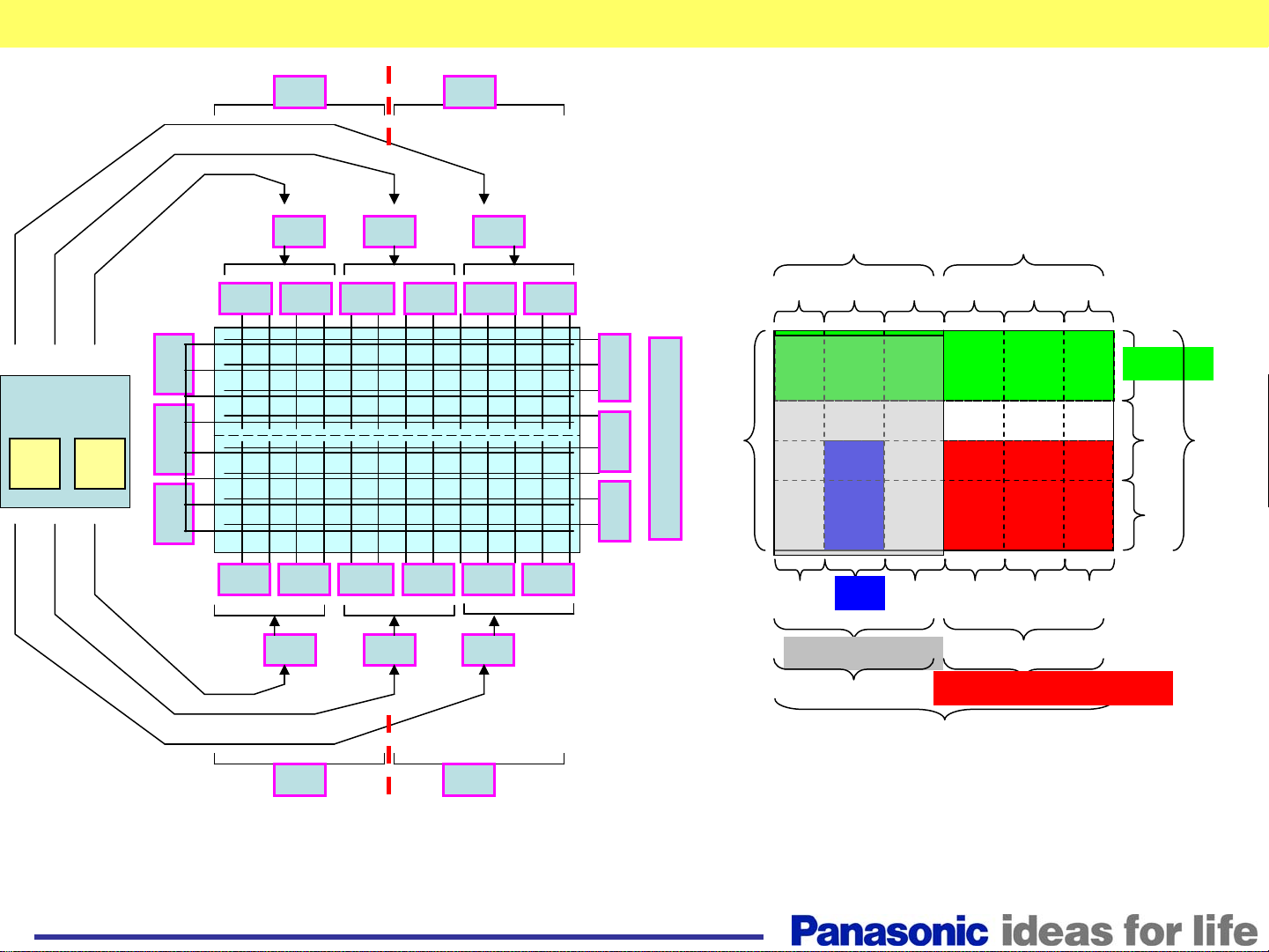
Relation of board and display area
DR2 DR1
Example of picture problems due to a defective board
D board
R L
SS2
SS
SS3
C6 C1C4
C7 CZC9 CYCXC8
CDCDCD
C2C3C5
SU
SM
SC
SS
(all)
SD
CDCDCD
DR1(1/4 of lower left) DR2(1/4 of lower right)
D( Left half)
D,DN, slot all
DR1(1/4 of upper Right)DR2(1/4 of upper Left)
C1C2C3C4C5C6
SU
SC
SM
(all)
SD
CZCYCXC9C8C7
D( Right Half )
DR1 DR2
11
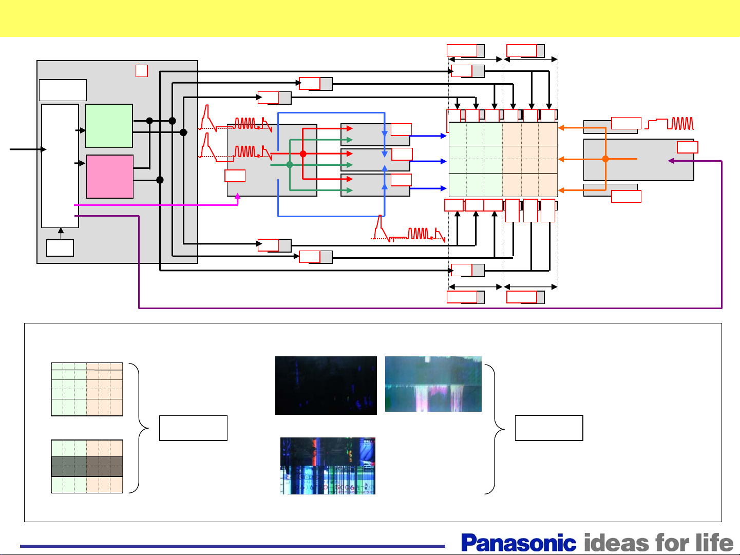
Page 12
Picture Trouble(1)
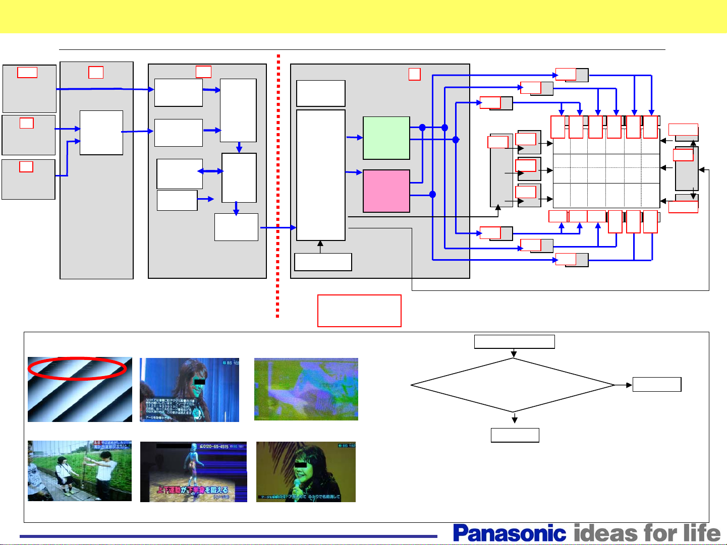
■Picture trouble(Vertical line all area, horizontal line, Color problem, Others)
HDD
DVI Input
HA
Video Input
HX
PC Input
■Sample
DS
Video
Signal
SW
LVDS
Convert
A/D
Convert
Picture
Signal
Processing
Micro
Computer
DN
OSD
I-P
Convert
Resize
OSD
TEST
LVDS
Convert
Micro
Computer
Convert
LVDS
・
Discharge
Control
EEPROM
Panel block
D
Picture data
Sub Field
Data
(Left half)
Test Pattern
Sub Field
Data
(Right half)
Test Pattern
Discharge control(SCAN)
Discharge control(SUS)
Picture data
■Flowchart for vertical line problem
Picture data
Picture data
CD
SC
Picture data
CD
Picture data
Picture Trouble
CD
SU
SM
SD
CD
CD
C
1
CD
C
C
C
C
C
C
SS2
6
SS
SS3
7
2
3
4
5
C
C
CXCYCZ
8
9
Thin horizontal line
Thin vertical line
at all screen
Discolor picture (No green)
Horizontal line noise
at half side (right)
Noise picture
Discolor picture (No blue)
Enter the service
mode to display the test pattern. Are there
vertical or horizontal lines?
Yes
D board
Note: The white test pattern, that contains numbers, is generated by the DN board.
Press the OK button of the remote control to display subsequent patterns
generated by the D board.
If you cannot enter the test pattern, unplug the connector D5 of
the D board to obtain a white raster.
No
DN board
12
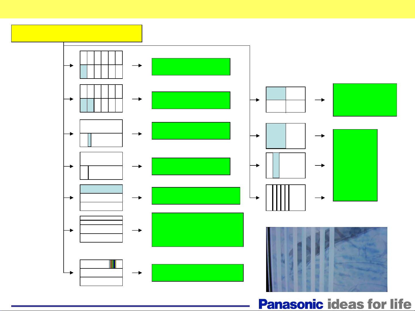
Page 13
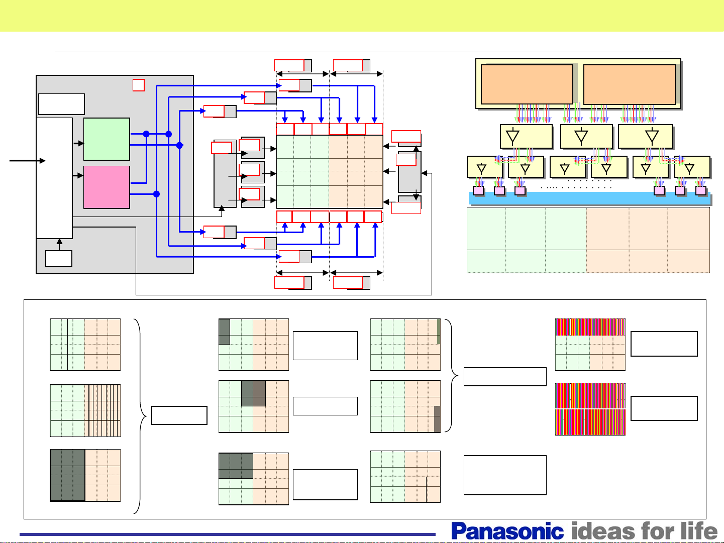
Picture Trouble(2)
■Picture trouble(Vertical line at part of screen, abnormal picture) Normal sound
Micro
Computer
Convert
Picture
LVDS
signal
Control
discharge
RROM
■Trouble sample
D
Picture data
Sub Field
Data
(Left half)
Test Pattern
Sub Field
Data
(Right half)
Test Pattern
Discharge control(SCAN)
Discharge control
(SUS)
Picture data
Picture data
Picture data
Picture data
CD
SC
Picture data
CD
CD
SU
SM
SD
CD
DR1 DR2
CD
C2
C3
C1
C4 C5
CD
DR2 DR1
C1-CZ
Module
C6
C7C8C9CXCYCZ
SS2
SS
SS3
Convert sub field
Convert sub field
Convert parallel serial
Convert parallel serial
Test pattern
Test pattern
CD CD CD
Buffer Buffer Buffer
C1 C2 C3 C4
180
Lines
Convert sub field
Convert sub field
Convert parallel serial
Convert parallel serial
Test pattern
Test pattern
C5
・・・・・・・・・・・・・
PANEL
PANEL
・・・・・・・・・・・・・・・・・・・
SU,SM,SD
Module
C6
DriverDriver
Driver
Through vertical thin line
D module
Interval vertical thin line at half of panel
Abnormal picture at half
1/4 abnormal
CD Module
DR1,2
Module
Vertical bar for 180 lines
Vertical bar for 360 lines
Thin vertical line
13
Plasma panel
D,SC
Module
Plasma panel
or
D module
Page 14
Picture Trouble(3)
Picture Data
Picture Data
Picture Data
V
F
VF0
SC
Scan control
Picture Data
Picture Data
Picture Data
Picture
signal
Micro
Computer
Convert
LVDS
Control
discharge
PROM
D
Sub Field
Data
(Left half)
Test Pattern
Sub Field
Data
(Right half)
Test Pattern
Discharge control
(SUS)
CD
CD
CD
SIU
SID
CD
VF
VF0
SU
SM
SD
San Drive
DR1 DR2
CD
C
C
C
C
C
1
2
3
4
C
C
CXCYCZ
9
CD
DR2 DR1
C
5
6
SS2
SUS DRV
SUS
DRV
SS
SS3
C
7
8
■Trouble sample
●Horizontal line at part of screen
Thin horizontal line
Horizontal bar same as board width.
SU,SM,SD
Module
●Abnormal Discharge
SC,D
Module
14
Page 15
Summary of Picture Trouble and Defective Board
Diagnosis of board defect
C1-CZ board
DR1 Or
CD board
DR2 board
C/CD/D board
C/CD/D board
SU/SM/SD board
SU/SM/SD board
Or Panel
Colored vertical
bar
SU/SM/SD board
15
D board
Page 16
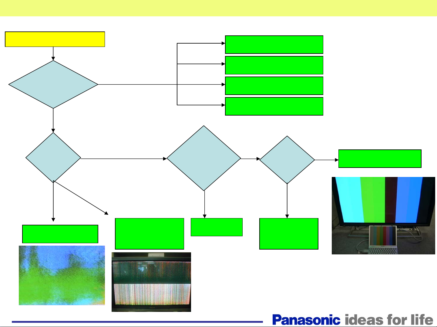
Picture Trouble all Area
Picture trouble
Do all the video
Inputs provide
the symptom?
All input
sources
What is the
symptom?
Abnormal
discharge
all area
all area
No
Group of vertical line
Video or PC
DVI
Video
PC
Do the
Internal Test
Patterns
provide the
same
symptom?
NG
DN or DS board
HDD board
HA board
HX board
OK
Is the OSD
visible on
screen?
NG
OK
DN board
SC/SS board
SU/SM/SD
board
D board
16
D or DN
board
Ex.RGB input(No red)
Page 17
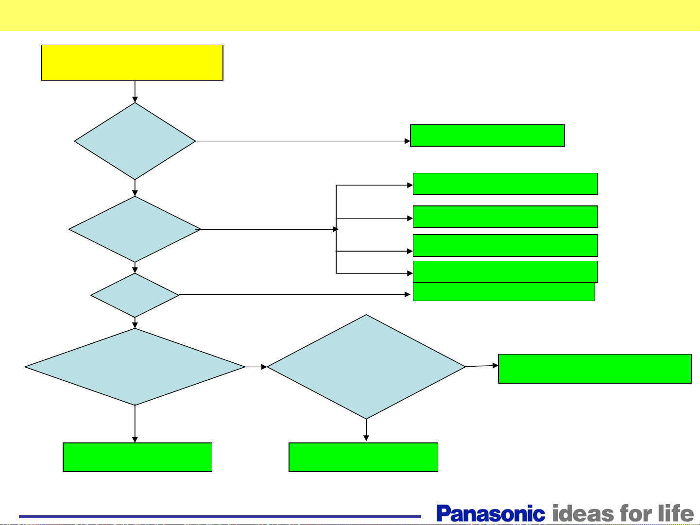
Picture Trouble (3)
No picture, green power LED
is lit.
Did the power
relay click on?
No
Yes
Is there video
from any of
the inputs?
If there is no video from
No
Is there
O.S.D?
Yes
NG
Disconnect CN D5 and turn the
unit ON. Does a white pattern
appear on screen?
No picture
Replace the P or D board
Video or PC
Replace the DN or DS board
DVI
Replace the HDD board
Video
Replace the HA board
PC
Replace the HX board
Replace the DN board
Disconnect the SU,SM, and
SD boards one at a time from
the SC board. Does 2/3 of a
picture appear?
Yes
SU or SM or SD board
Yes
DN board
No
SC or SS or SD
17
Page 18
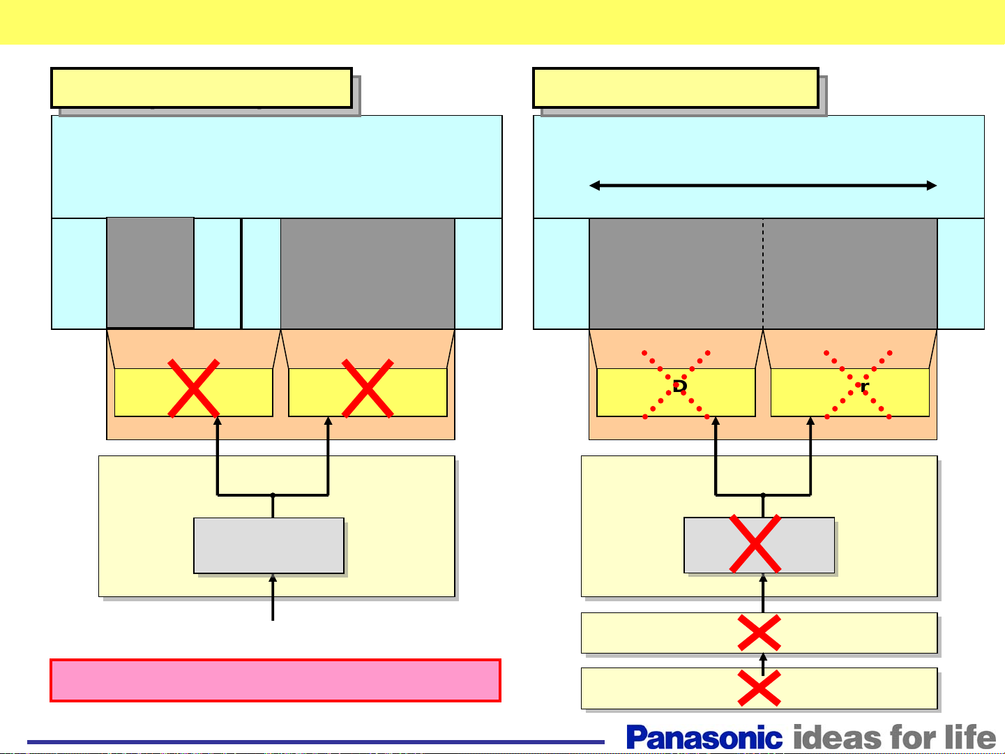
Picture Trouble (Vertical line) (1)
Panel (IC driver) defect
Panel (IC driver) defect
PDP panel
Thin line
Abnormal
Data Driver
IC
Data Driver
Abnormal
IC
C or CD circuit defect
C or CD circuit defect
PDP panel
15cm approx.
Abnormal
Data Driver
IC
Data Driver
IC
Buffer IC
Buffer IC
(RGB)
(RGB)
Data driver IC defect = PDP panel defect
18
C boardC board
CD board
D board
Buffer IC
Buffer IC
(RGB)
(RGB)
Page 19

Troubleshooting for No Power
Troubleshooting for No
Power
19
Page 20

Dead - Power LED does not Light (1/2)
Power LED Status
OFF
AC Power Cord or P Board
Defective Block
How to find the defective board
D1603
D1604
D1703
D501
D1603
D1604
D1703
D501
AC
P(SS)
F
1
1
3
F
F904
F901
F903
F900
P
F
8
1
4
F
9
1
4
9
1
3
P
9
1
3
FUSE FUSE
P(SC)
Are fuses F900 and F901
on the F Board open?
S
Tr
MPU
Power
SW
No
STB5V
STB5V
Power Supply / Protect Circuit
PC
P
PC
25
202
10
10
P
PC
25
203
10
10
PC
201
10
D
D
25
IC9011
STB3.3V
Are fuses F903 and F904
D
DN
3
1210 12
DN
2
IC4308
STB3.3V
DN3DS
18 18
30 30
MPUMPU
No
on the F Board open?
DS
3
20
Yes (P(SC) NG)
Are diodes D1603 or
D1604 on the P(SC) Board
ok?
Yes
Are diodes D1703 or
D501 on the P(SC) Board
ok?
Yes
Fuses in P(SC) Board
No
P(SUS)
Board
No
P(MULTI)
Board
Continued on page 2/2
Yes (P(SS) NG)
Are diodes D1603
or D1604 on the P(SS) Board
ok?
Yes
Are diodes D1703
or D501 on the P(SS) Board
ok?
Yes
Fuses in P(SS) Board
No
No
P(SUS)
Board
P(MULTI)
Board
Page 21

Dead - Power LED does not Light (2/2)
Power LED Status
OFF
F904
F901
Yes
Yes
Is there
SW on?
F
F903
F900
F
1
AC
1
3
Continued from page 1/2
Is there STB 5V
output at pin 10 of CN P25 on the
P(SS) Board after turning the
power SW on?
Is there
STB 5V output
at pin 10 of PC201
after turning the
power SW
on?
STB 5V output at pin 12 of
CN D3 after turning the power
Defective Block
AC Power Cord or P Board
D1603
D1604
D1703
FUSE FUSE
D1603
D1604
D1703
No
and GND.
No
D501
D501
S
P(SS) Board
Yes
D Board
No
F
8
1
4
F
9
1
4
Yes
P(SS)
P
9
1
3
P(SC)
P
9
1
3
Remove AC power.
Disconnect CN P25.
Is there a short
at pin 10 of socket P25
P(SS) Board
DN Board
Tr
MPU
Power
SW
No
STB5V
STB5V
How to find the defective board
Power Supply / Protect Circuit
PC
P
PC
25
202
10
10
P
PC
25
203
10
10
Disconnect
CN PC201.
Is there a
Short at pin 10 of
Socket PC201 and
GND?
Yes
PC Board
short at pin 18 of
21
D
PC
25
201
10
No
Is there a
socket DS3 and
GND?
Yes
DS Board
D
IC9011
STB3.3V
Disconnect
CN D3.
Is there a
short at pin 12 of
socket D3 and
GND?
Yes
D Board
No
DN
D
DN
3
2
1210 12
No
Disconnect
CN DS3.
P(SC) Board
DN3DS
18 18
IC4308
STB3.3V
30 30
MPUMPU
Disconnect
CN DN3.
Is there
a short at pin 18 of
socket DN3 and
GND?
Yes (DN short)
DN Board
DS
3
No
Page 22

Power LED’s Response to Shutdown Operation
Shutdown (SOS)
Troubleshooting
22
Page 23

Protection Circuit23LED blinks 1 time
LED blinking
LED
Blinking time
2
3
4
5
6
7
8
9
10
11
13
15
SOS item
Micro computer error1
15V SOS
3.3V SOS
P board SOS
(Vsus, Vda )
5V SOS
SC board Power SOS
SC board floating output SOS
Data signal power collect SOS
SS board power collect SOS
ROM access error
DS board, Slot power SOS
FAN SOS
DN board power SOS
(3.3V, 2.5V, 1.8V, 1.5V)
Model code error
D board CPU
IC9003’s Pin No.
No.5 L:SOS
No.71 L:SOS
No.70 L:SOS
No.74 H:SOS
No.69 L:SOS
No.72 H:SOS
No.76 H:SOS
No.73 H:SOS
EEPROM data
DN board CPU
IC4701’s Pin No.
No.165 L:SOS
No.134 L:SOS
No.132 L:SOS
IC3004 contact
No.130 H:SOS
No.139 L:SOS
EEPROM data
Defective board mainly
D, DN
P(Multi/SS), D, DN,SS,PB,DR1/2
D
P(SUS/SC),P(Multi/SC),
P(SUS/SS),P(Multi/SS)
P(Multi/SC),P(Multi/SS),
D, DN,C1-CZ, SC, SS, DR1/2
SC, SC2, SU, SM, SD D,
P(SUS/SC),P(Multi/SC)
DR1/2,D, P(SUS/SC),P(Multi/SC),
P(SUS/SS),P(Multi/SS), C1-CZ
SS, D, P(SUS/SC),P(Multi/SS)
D
SLOT1, SLOT2, SLOT3, DS
FAN ,PB
DN ,P(SUS/Multi)
DN
RED LED
Blinking
Blinking
No light
Blinking times
1.0s
3.0s
Page 24

Trouble Mode
Defective Board
Warning: Disconnect AC Power prior t o
making any disconnection or connection
Communication Error
Replace the D
board
No
DN, D
Unplug the TV and disconnect
connector DN2 on the DN Board or D3
of the D board . Plug in the TV.
Did the TV turn on by
itself with the following
conditions?
Power LED = Off
SC LED= On
SS LED = ON
Yes
Replace the DN
board
24
Page 25

Panel SOS – Power LED Blinks 2 Times (SS Side)
Trouble Mode Defective Board
15V line SOS P(Multi/SS), D, DN,SS,PB,DR1/2 Board
Power Supply / Protect Circuit
PC
202
1
2
PB31
1
PC
DR
11
SS
35
SS
12
SS
42
DR
PC
201
1
1
2
15V
D
D25
1
2
PB
DR2
SS
DR1
15V
DC
CONV.
Q9051
Q9050
DN
IC4701
P(Multi/SS)
15V
15V
15V
P25
1
2
P5
1
P12
4
D3
DN
71
2
166
IC9003
15V SOS
67
PANEL_SOS
8
15
8
15
15V
DC
CONV.
Disconnect the unit
from AC Power
Disconnect CN P25.
Is pin 1 of
Socket P25 shorted
to GND?
Disconnect CN P12
Is pin 4 of
socket P12 shorted
to GND?
Yes
Disconnect CN P5
Yes
SS Side Troubleshooting
How to find the defective board
Disconnect CN D25. Disconnect CN DN2.
Yes
GND?
No
Yes
Is pin 15 of
socket DN2 shorted
to GND?
Yes
DN Board
No
D Board
No
DR2 Board
No
No)
Is pin 1 of
socket D25 shorted
to GND?
Yes
Disconnect CN DN2
Is pin 15 of
socket DN2 shorted
to GND?
DN Board
Disconnect CN SS35
Is Test Point TP15V
on the SS board shorted to
Disconnect CN SS42
No
P(SS)
Board
Note: The check position is the connector on the board ,
not cable's connector.
25
Is pin 1 of
socket P5 shorted to
GND?
Yes
P(SS) Board
No
PB
Board
Is Test Point TP15V
on the SS board shorted
to GND?
Yes
SS Board
No
DR1 Board
Page 26

Panel SOS – Power LED Blinks 2 Times (SC Side)
Trouble Mode Defective Board
15V line SOS P(Multi/SS), D, DN,SS,PB,DR1/2 Board
Power Supply / Protect Circuit
How to find the defective board
Disconnect the unit
from AC Power.
Disconnect CN P23,
P5, and P12.
Is pin 1 of
socket P23 shorted to
GND?
No
Disconnect CN SC23 and SC80.
Is pin 1 of
socket SC23 shorted to
GND?
No
Disconnect CN DS4
Yes
Yes
P(SC)
Board
SC Board
SC Side Troubleshooting
Disconnect
CN DR11. Is pin 6 of
socket DR11
shorted to
GND?
No
SC2 Board
Yes
DR2 Board
Note: The check point is the socket on the board ,
not the cable's connector.
Is pin 1 of
socket DS4 shorted
to GND?
No
Disconnect CN DR1
Is pin 6 of
socket DR1 shorted
to GND?
No
26
Yes
DS Board
Yes
DR1 Board
Yes
Page 27

Panel SOS – Power LED Blinks 3 Times
Trouble Mode Defective Board
3.3V line SOS D Board
How to find the defective board
The defective board is D ONLY.
Power Supply / Protect Circuit
P(Multi/SS)
+15V
P25
1
2
PC
202
1
2
PC
PC
201
1
2
D25
1
2
D
IC9807, Q9803
15V->3.3V
DN
+3.3V
IC4701
IC9003
70
3.3V SOS
D3
DN2
67
PANEL_SOS
8
8
166
27
Page 28

Panel SOS - Power LED Blinks 4 Times
Trouble Mode
Power Supply SOS
P(SUS/SC),P(Multi/SC) ,P(SUS/SS),P(Multi/SS) Board
Power Supply / Protect Circuit
SC82
1
SC
VSUS
SC2
Power
SW
S
P(SUS/SC)
P(Multi/SC)
Vsus
Vda
PS SOS
Vda SOS
PS SOS
Vda SOS
P(SUS/SS)
P(Multi/SS)
Vda
Vsus
S
34
P2
1
P11
1
P12
1 2
P25
16
20
P25
16
20
P12
1 2
P2
1
1
SC
12
SC34
PC
203
16
20
PC
202
16
20
VSUS
Vda
PC
Vda
SC2
PC
201
16
20
PC
201
16
20
SS2
SS
12
Defective Board
Is the green
SC
13
SC
14
PC
25
16
20
DR1 & DR2
boards
Left Side
D
DN
D3
DN2
74
PS SOS
68
67
PANEL_SOS
8
8
166
IC4701
IC9003
VDA_DET
Disconnect CN P12 of P(SC)
board and SC34 of the SC2
board. Insert the SC34 connector
into pins 8, 9, and 10 of socket P12.
LED on the SC
Board lit?
Yes
Is the green
LED on the SS
Board lit?
Yes
Turn the Power SW ON.
Yes (Vda NG)
Is there Vda
Voltage at pin 1 of CN P12 of
Vda
SS
1
Vda
VSUS
SS
35
SS
42
DR1 & DR2
boards
Right Side
the P(SC) Board before
shutdown?
Yes
P(Multi/SS) Board
No
P(SUS/SC)
P(Multi/SC)
Board
No
P(SUS/SS)
P(Multi/SS)
Board
No
P(Multi/SC)
Board
28
Page 29

Panel SOS – Power LED Blinks 5 Times (1/6)
Trouble Mode
5.0V line SOS
P(SS)
+5V
P(SC)
+5V
Defective Board
P(Multi/SC),P(Multi/SS),D, DN,C1-CZ,
SC, SS, DR1/2 Board, Panel(IC)
C
21
CY
1
PC
205
PC
201
7
9
C2
C
22
CY
1
2
C
23
CY
3
2
D25
SC
20
5V
DR2
DR1
DR2
DR12
P25
P25
SC
C1
C
11
CA1 CA2 CA3 CA4 CA5 CA6 CA7 CA8 CA9
5V
CB1 CB2 CB3 CB4 CB5 CB6 CB7 CB8 CB9 C 10BC 11BC 12BC 13BC 1
CZ
1
PC
204
1
2
PC
202
7
9
7
9
7
9
PC
203
7
9
PC
How to find the defective board
Power Supply / Protect Circuit
41
91
C4
C
C
40
43
C
C
C
C
92
C
42
10
A
C 11AC 12AC 13AC 14AC 15AC 16
C
93
C
90
P5V
Q9053
IC4701
C3
C
32
CX
2
CXCYCZ
D
7
9
DN
C
31
Panel
CX
1
C9
C
53
C
83
C
80
D35D32 D34D20
C5
C
52
C82C
C8
Q9054
D3
DN
C
51
B
C
81
88
2
C
61
4
C 15BC 16
71
69
67
8
8
166
C6
C
C7
IC9003
P5V SOS
5V
30
30
A
B
PANEL_SOS
5V
DR12
DR2
SS
DR1
SS
44
DR2
5V
29
Page 30

Panel SOS – Power LED Blinks 5 Times (2/6)
Trouble Mode
5.0V line SOS
Power Supply / Protect Circuit
Turn on the power SW. Turn on the power SW.
output at pin 7 of CN PC203
before shutdown ?
Defective Board
P(Multi/SC),P(Multi/SS),D, DN,C1-CZ,
SC, SS, DR1/2 Board, Panel(IC)
5 times
blink
Is there 5V
7 times
blink
7 times
Diag.
Yes
Is there 5V
output at pin 7 of CN PC202
before shutdown?
■D,P,DN,SC,SS Diag.
Disconnect CN D20 and C88.
Turn on the power SW.
Yes
(SC, SS NG)
Does the unit
power up?
No
(D or P or C, or Panel NG)
Disconnect CN D20, D31~D36.
Disconnect PC204 and PC205.
Turn on the power SW.
Yes
(C, or DR, or Panel NG)
Does the unit
power up?
No
Disconnect AC from the unit.
Disconnect CN D3 or CN DN2.
Yes
Is pin 30 of CN DN2
shorted to GND
How to find the defective board
Connect CN D20. Turn on
the power SW.
No
SC Board
Power SW
OFF
Yes
Does the unit
power up?
Yes
SS Board
Perform C, DR, Panel
Diagnostic as shown on page 3/6.
DN Board
No
Turn on the power SW.
Is there 5V
output at pin 7 of CN PC202
before shutdown?
No
D (or PC)
Board
Yes
P(SC)
Board
No
P(SS) Board
No
D Board
30
Page 31

Panel SOS – Power LED Blinks 5 Times (3/6)
■C, CR, Panel Diag.
Disconnect
CN C43.
Is pin 1 of
socket C43 Shorted to
GND?
Yes (C1~C6,DR,Panel NG)
Disconnect
CN C52.
Is pin 1 of
socket C43 shorted to
GND?
Yes (C1~C6,DR,Panel NG)
Disconnect
CN C42 or C53.
Is pin 1 of
socket C43 shorted to
GND?
Yes (C1~C6, Panel NG)
Disconnect
CN C22.
No (C7~CZ, DR, Panel NG)
No
No
DR2(SS side)
Board
DR1(SC side)
Board
Disconnect
CN C51 or C61.
Is pin 1 of
socket C52 shorted to
GND?
Yes
No
How to find the defective board
Connect CN C51 and C61.
Disconnect CN CA15 and CA16.
Is pin 1 of
CN C52 shorted to
GND?
Yes
C6 Board
Disconnect
CN CA12~CA14. Is pin 1 of
socket C52 shorted to
GND?
No
Panel
No
Panel
Is pin 1 of
socket C43 shorted to
GND?
Yes
(C1~C4, Panel NG)
Continued on page 4/6
(C5~ C6,
No
Panel, NG)
Yes
C5 Board
Continued on
page 5/6
31
Page 32

Panel SOS – Power LED Blinks 5 Times (4/6)
■C, CR, Panel Diag.
From page 3/6
Disconnect
CN C23 or C32.
Is pin 1 of
socket C43 shorted to
GND?
Disconnect
CN C31 or C41.
Is pin 1 of
socket C43 shorted to
GND?
Disconnect
CN CA9~CA11.
Yes
(C3~C4,
Panel NG)
Yes
No
Disconnect
CN C11 or C21.
Is pin 1 of
socket C22 shorted to
GND?
Yes
Connect CN C31 and C41.
Disconnect CN CA6~CA8.
Is pin 1 of
socket C43 shorted to
GND?
Yes
C3 Board
No
No
How to find the defective board
Connect CN C11 and C21.
Disconnect CN CA1 and CA2.
Is pin 1 of
socket C22 shorted to
GND?
Yes
C1 Board
Disconnect
CN CA3~CA5.
Is pin 1
of socket C22 shorted
to GND?
Yes
C2 Board
Panel
No
Panel
No
Panel
Is pin 1 of
socket C43 shorted to
GND?
Yes
C4 Board
No
Panel
32
Page 33

Panel SOS – Power LED Blinks 5 Times (5/6)
■C,CR,Panel Diag.
How to find the defective board
From page 3/6
Disconnect CN C92.
Is pin 1 of
socket C92 shorted to
GND?
Yes (C7~CZ,DR,Panel NG)
Disconnect CN C82.
Is pin 1 of
socket C92 shorted to
GND?
Yes (C7~CZ,DR,Panel NG)
Disconnect CN CY2.
Is pin 1 of
socket C92 shorted to
GND?
Yes (C1~C6, Panel NG)
Disconnect CN C93 or 83.
Is pin 1 of
socket C92 shorted to
GND?
Yes
(C9~CZ,
Panel NG)
No
No
No
No
(C7~C8,
Panel NG)
Check Connection
PC204- CN C43,
PC205- CN C92.
DR1(SS side)
Board
DR2(SC side)
Board
Disconnect CN C81 or 71.
Is pin 1 of
socket C82 shorted to
GND?
Yes
No
Connect CN C81 and C71.
Disconnect CN CB15 and CB16.
Is pin 1 of
socket C82 shorted to
GND?
Yes
C7 Board
Disconnect
CN CB12~CB14.
Is pin 1 of
socket C82 shorted to
GND?
Yes
C8 Board
No
No
Panel
Panel
Go to page 6/6
33
Page 34

Panel SOS – Power LED Blinks 5 Times (6/6)
■C,CR,Panel Diag.
How to find the defective board
From page 5/6
Disconnect CN CY3 or CX2.
Is pin 1 of
socket C92 shorted to
GND?
Yes
(C9~CX,Panel NG)
Disconnect CN C91 or CX1.
Is pin 1 of
socket C92 shorted to
GND?
Yes
Disconnect CN CB9~CX1.
No
(CY~CZ, Panel NG)
No
Disconnect CN CY1 or CZ1.
Is pin 1 of
socket CY2 shorted to
GND?
Yes
Connect CN C91 or CX1.
Disconnect CB6~CB8.
Is pin 1 of
socket C92 shorted to
GND?
Yes
CX Board
No
No
Panel
Connect CN CY1 and CZ1.
Disconnect CN CB1 and CB2.
Is pin 1 of
socket CY2 shorted to
GND?
Yes
CZ Board
Disconnect
CN CB3~CB5. Is pin 1 of
socket CY2 shorted to
GND?
Yes
CY Board
No
Panel
No
Panel
Is pin 1 of
socket C92 shorted to
GND?
Yes
C9 Board
No
Panel
34
Page 35

Panel SOS – Power LED Blinks 6 Times (1/2)
Trouble Mode
SCAN Driver SOS
Power Supply / Protect Circuit
P(SC)
Vsus
15V
Vsus
15V
+5V
P(SS)
+5V
1
P25
P25
P2
1
P23
P11
1
P12
4
7
16
9
7
9
2
SC34
S34
Power
SW
SC2
REG.
REG.
REG.
REG.
REG.
REG.
PC
201
7
9
D25
PC
203
PC
202
SC82
1
SC12
4
S
PC
7
9
7
9
Defective Board
SC, SC2, SU, SM, SD D,
P(SUS/SC),P(Multi/SC) Board
2
2
2
6
12
4
9
SC
TPVSUS
VBK
P5V
PULSE
SC
SOS
D
15V
VSET
15V
16V_F2
16V_F
VSCN
VAD
BUFFER
72
D3
DN2
11
13
17
21
7
9
SC84
1
4 8
SC83
1
5
D20
12
14
18
22
2
2
6
P5V
SC23
1
SC81
1
4 8
SC80
1
5
11
13
17
21
SC20
2
6
12
17
SC2
1
14
18
22
1
13
20
11
SC
PULSE
DN
IC4701
Energy Recovery
Circuit
D6583
LED(G)
SC SOS
SC SOS
67
8
8
166
5V(SC3)
REG.
5V(SC1)
REG.
IC9003
MPU
PANEL_SOS
FET
FET
DRIVER
IC6581
1/2Vo SOS
IC6353
VBK SOS
IC6861
VSCN SOS
IC6871
VAD/16V SOS
Q6824
VSET SOS
5V(SC1) SOS
5V(SC3) SOS
Vfo
Vf
SC49SU
SC41SU
SC42SU
SC50SM
SC43SM
SC46SM
SC51SM
SC52SD
SC47SD
SC48SD
49
41
42
50
43
46
51
52
47
48
5V
SC PULSE(SU)
5V
Vf
VSCN
Vf, Vfo
5V
SC PULSE(SM)
VSCN
Vf, Vfo
VSCN
Vf, Vfo
5V
SC PULSE(SM)
5V
SC PULSE(SD)
5V
Vf
VSCN
Vf, Vfo
Energy Recovery DET condition
・
NO VSUS
・
NO SCAN PULSE(SC20 17-20pin)
・
NO P5V(SC20 1pin)
Floating Voltage DET condition
・
NO 15V
・
NO SCAN PULSE(SC20 4-6pin)
・
NO P5V(SC20 1pin)
SU
SM
SD
35
Page 36

Panel SOS - Power LED Blinks 6 Times (2/2)
Trouble Mode
SCAN Driver SOS
SC, SC2, SU, SM, SD D,
P(SUS/SC),P(Multi/SC) Board
Power Supply / Protect Circuit
Disconnect CN SC2, SC23, SC81, and
SC80 of the SC Board. Turn the unit on.
Does it
power up?
Connect CN SC2, SC23, SC81,
and SC80. Turn the unit on.
Does the SC board LED
light before shutdown ?
Disconnect the SM, SU, and SD boards
from the SC board. Turn the unit on.
Connect the SU board to the SC board. Disconnect the
SD and SM boards from the SC board. Turn the unit on.
Does it power up?
Connect the SD board to the SC board. Disconnect the
SU and SM boards from the SC board. Turn the unit on.
Does it power up?
No
Yes
No
Yes (SC Floating Volt NG)
Does it power up?
Yes (SU,SM,SD NG)
Yes (SM,SD NG)
Yes (SM NG)
Defective Board
4 times blink
7 or 8 times blink
SC (or D) Board
=SC, SU, SM, SD, SC2, D
No
No
SU Board
SD Board
No
D Board
How to find the
defective board
Disconnect CN P11, P12. Place a
jumper across pins 8 and 10 of CN P12.
Turn the unit on.
Is there VSUS
voltage at pin 1 of CN P2
and 15V at pin 1 of CN P23
before shutdown?
Yes
SC2 Board
No
(VBK,VSCN,VAD,16V,
VSET,SC PULSE NG)
Disconnect CN SC84 and SC83.
Turn the unit on.
Are the following
voltages present before shutdown?
TPVSCN, TPVAD, TPVSET,
TPF16V, TPF16V2, and TPVBK
on the SC2 Board (*)
Yes (SC PULSE NG)
SC (or D) Board
No
P(SC) Board
=SC, SC2, D
No
SC2 Board
* SC Floating Volt. SOS
SM Board
36
Page 37

Panel SOS – Power LED Blinks 7 Times (1/5)
Trouble Mode
DATA Driver SOS
DR2
DATA
PULSE
5V, SOS
DR1
SC
12
DR2
DATA
PULSE
5V, SOS
DR12
SC2
Vda
15V
Vda
15V
Vda
15V
DR13
DR3
Vda
Vda
Defective Board
DR1/2,D, P(SUS/SC),P(Multi/SC),
P(SUS/SS),P(Multi/SS), C1-CZ Board
Power Supply / Protect Circuit
C
24
C
21
CY
CY4
C2
C22C
20
C
23
CY2
CY
3
CY0
1
DR
DR
DR
SC
13
SC
14
DR
11
DR
15
DR
14
C1
C14
CZ4
11
CZ
C
1
4
5
1
CA1 CA2 CA3 CA4 CA5 CA6 CA7 CA8 CA9 C 10AC 11AC 12AC 13AC 14AC 15AC 16
CB1 CA2 CB3 CB4 CB5 CB6 CB7 CB8 CB9 C 10BC 11BC 12BC 13BC 14
C
32
CX
How to find the defective board
■DR1/2 P(SC/SS),D Diag.
5V
SOS
41
91
5V
C4
C44
C40
C
C
C90
C94
C9
42
C
93
C
C5 C6
C52C
C
50
C
53
C
83
C82
C84
C8
54
51
C
B
C
81
C64
C
61
A
C 15BC 1
C
71
C74
C7
DR13 DR12
DR
14
Vda
DR
15
DR
Vda
11
15V
SS
35
SS
42
DR
Vda
1
B
6
DR
5
DR
4
15V
Vda
DR3
DATA
PULSE
5V,SOS
SS
Vda
15V
DATA
PULSE
5V, SOS
DR2
DR1
DR2
SS
12
C3
SOS
C34
C
31
Panel
CX4
CX
1
2
CXCYCZ
P(SC)
Vda
15V
+5V
P(SS)
+5V
Vda
15V
1
1
P12
4
P25
P25
P12
4
PC
2
PC203
7
9
7
9
2
7
9
PC202
7
9
PC201
7
9
D25
7
9
D31D32 D33
DATA ENERGY
RECOVERY PULSE
P5V
D
DN
D36
D3
DN2
IC4701
D35
8
8
166
PANEL_SOS
DATA
76
ENERGY
RECOVERY
67
SOS
PANEL_SOS
IC9003
Data Energy Recovery DET condition
・
NO VDA, 15V
・
NO DATA回収PULSE(DR2/12 3~6pin)
・
NO P5V(DR2/12 1,2pin)
37
Page 38

Panel SOS – Power LED Blinks 7 Times (2/5)
Trouble Mode
DATA Driver SOS
SOS
C3
5V
C40
C
41
CA9 C 10AC 11AC 12AC 13AC 14AC 15AC 16
Defective Board
DR1/2,D, P(SUS/SC),P(Multi/SC),
P(SUS/SS),P(Multi/SS), C1-CZ Board
C4
C44
C
42
C5
C50 C52 C54
C
53
Panel
Upper Right Quadrant
Rear View
C
51
61
How to find the defective board
Power Supply / Protect Circuit
C6
C64
C
A
DR
DR
DR
SS
35
SS
42
DR
DR13 DR12
14
15
11
1
Vda
15V
Vda
DATA
PULSE
5V,SOS
Vda
15V
DR2
SS
DR2
SS
12
Large view
of VDA
distribution to
the Upper
Right quadrant
of the panel
P(SC)
Vda
15V
+5V
P(SS)
+5V
Vda
15V
1
P12
4
P25
7
9
P25
P12
1
D31D32 D33
DATA ENERGY
2
7
9
2
4
PC203
7
9
PC202
7
9
PC
PC201
7
9
D25
7
9
RECOVERY PULSE
P5V
DN
D36
PANEL_SOS
D
D3
DN2
IC4701
D35
8
8
166
PANEL_SOS
76
67
IC9003
DATA
ENERGY
RECOVERY
SOS
38
Page 39

Panel SOS – Power LED Blinks 7 Times (3/5)
Trouble Mode
DATA Driver SOS
■DR1/2 P(SC/SS),D Diag.
Disconnect CN DR12 of the DR2
Board (SS side). Turn the unit on.
Does it power up?
No
Disconnect CN DR2 of the DR1
Board (SS side). Turn the unit on.
Does it power up?
No
Disconnect CN DR2 of the DR1
Board (SC side). Turn the unit on.
Does it power up?
No
Disconnect CN DR12 of the DR2
Board (SC side). Turn the unit on.
Does it Power up?
No
D Board (*)
P(SUS/SS),P(Multi/SS), C1-CZ Board
Yes
Yes Are there Vda
Defective Board
DR1/2,D, P(SUS/SC),P(Multi/SC),
Connect CN DR12. Disconnect
CN DR13~DR15 of the DR2 Board.
Turn the unit on.
Does it power up?
No
Disconnect CN SS35 and SS42.
Turn the unit on.
output at pin 1 of CN P12 and
15V output at pin 4 of CN P12
before shutdown ?
No
Yes
Yes
P(SS) Board
Connect CN DR2. Disconnect CN DR3~DR5
of the DR1 Board. Turn the unit on.
Connect CN DR2. Disconnect CN DR13~DR15
of the DR2 Board. Turn the unit on.
How to find the defective board
DR2 Board
Yes
Does it power up?
No
Does it power up?
DR2 Board
Yes
(C4~C6,Panel)
Connect CN DR2. Disconnect
CN DR3~DR5 of the DR1 Board.
Turn the unit on.
Does it power up?
No
DR1 Board
Yes
(CX~CZ, Panel)
No
DR1 Board
Yes
(C1~C3,Panel)
Power SW
OFF
Yes
(C7~C9,Panel)
Power SW
OFF
Power SW
OFF
Power SW
OFF
C4~C6,
Panel Diag.
C7~C9,
Panel Diag.
C1~C3,
Panel Diag.
CX~CZ,
Panel Diag.
39
Page 40

Panel SOS – Power LED Blinks 7 Times (4/5)
Trouble Mode
DATA Driver SOS
■C1~C3 Panel Diag.
Disconnect CN C34 and C32.
Are pins 1~4 and 6~11 of CN C34
shorted to GND?
Disconnect CN C11 or C21.
Are pins 1~4 and 6~11 of
CN C24 shorted to GND?
■C4~C6 Panel Diag.
Disconnect CN C44 and C42.
Are pins 1~4 and 6~11 of CN C44
shorted to GND?
Disconnect CN C51or C61.
Defective Board
DR1/2,D, P(SUS/SC),P(Multi/SC),
P(SUS/SS),P(Multi/SS), C1-CZ Board
Disconnect CN CA3~CA5.
Yes
and 6~11 of CN C24 shorted
No
Yes
No
Yes
No
Are pins 1~4
to GND?
How to find the defective board
Disconnect CN CA6~CA8.
Are pins 1~4
and 6~11 of CN C34 shorted
to GND?
No
C2 Board
No
Panel
Disconnect CN CA9~CA11.
Are pins 1~4
and 6~11 of CN C44 shorted
to GND?
No
Disconnect CN CA1~CA2.
Are pins 1~4
and 6~11 of CN C14 shorted
to GND?
No
Yes
Panel
Panel
Panel
C4 Board
Yes
Yes
C3 Board
C1 Board
Are pins 1~4 and 6~11 of CN C54
shorted to GND?
No
Disconnect CN CA15~CA16.
Are pins 1~4
and 6~11 of CN C64 shorted to GND?
No
Panel
Yes
Yes
C6 Board
40
Disconnect CN CA12~CA14.
Are pins 1~4
and 6~11 of CN C54 shorted
to GND?
No
Panel
Yes
C5 Board
Page 41

Panel SOS – Power LED Blinks 7 Times (5/5)
Trouble Mode
DATA Driver SOS
■C7~C9 Panel Diag.
Disconnect CN C94, C93, and C32.
Are pins 1~4 and 6~11 of CN C94
shorted to GND?
Disconnect CN C71 or C81.
Are pins 1~4 and 6~11 of CN C84
shorted to GND?
■CX~CZ Panel Diag.
Disconnect CN CX4 and CX2.
Are pins 1~4 and 6~11 of CN CX4
shorted to GND?
Disconnect CN CZ1or CY1.
Are pins 1~4 and 6~11 of CN CY4
shorted to GND?
Defective Board
DR1/2,D, P(SUS/SC),P(Multi/SC),
P(SUS/SS),P(Multi/SS), C1-CZ Board
Yes
No
Yes
No
Yes
Disconnect CN CB12~CB14.
and 6~11 of CN C84 shorted
No
Disconnect CN CB6~CB8.
and 6~11 of CN CX4 shorted
Disconnect CN CB3~CB5.
How to find the defective board
Disconnect CN CB9~CB11.
Are pins 1~4
and 6~11 of CN C94 shorted
to GND?
No
Are pins 1~4
to GND?
No
Are pins 1~4
to GND?
No
Panel
Panel
Yes
Yes
C8 Board
Disconnect CN CB15~CB16.
Are pins 1~4
and 6~11 of CN C74 shorted
to GND?
No
CX Board
Panel
Panel
Yes
C9 Board
Yes
C7 Board
No
Disconnect CN CB1~CB2.
Are pins 1~4 and 6~11 of CN Z54
shorted to GND?
No
Panel
Yes
CZ Board
Are pins 1~4
and 6~11 of CN CY4 shorted
to GND?
No
Panel
41
Yes
CY Board
Page 42

Panel SOS – Power LED Blinks 8 Times
P(SS)
Vsus
15V
+5V
Trouble Mode
SUS Driver SOS
SS, D, P(SUS/SC),P(Multi/SS) Board
Power Supply / Protect Circuit
P2
1
P12
P25
16
C8
C80
CD IC6152
D25
7997
D34
P5V
SS PULSE
PC
PC
202
7
7
9
9
PC
201
SS12
C88
1
3
898
D
SS2
1
SS44
1
3
9
SS
TPVSUS
P5V
SS
PULSE
SOS
IC9003
73
SS SOS
15V
BUFFER
Defective Board
Energy Recovery
Circuit
D6253
LED(G)
VE2 REG.
VE REG.
SS’2 FFC CABLE DET
FET
FET
FET
DRIVE
R
IC6261
Ve SOS
1/2Vo SOS
FET
SS OUT
How to find the defective board
Turn the power switch on.
Does the SS board LED light
before Shutdown?
Yes
Are the
FFC cables that
connect the SS, SS2 and
SS3 boards properly
seated?
Yes
SS Board
No
Reseat the
FFC Cables of the
SS, SS2, SS3 Boards
No
P(SC)
+5V
P25
7
9
PC
203
7
9
DN
IC4701
D3
DN2
67
PANEL_SOS
8
8
166
Energy Recovery DET condition
・
NO VSUS
・
NO SS PULSE(S44 3~8in)
・
NO P5V(SS44 1pin)
42
Disconnect the CN SS2.
Turn the unit on.
Does VSUS
appear at pin 1 of
CN P2 before
shutdown?
Yes
( SS or D(SS_PULSE) NG)
SS ( or D) Board
No
P Board
Page 43

Panel SOS – Power LED Blinks 9 Times
Trouble Mode
ROM access error
Defective Board
D
Replace the D board.
43
Page 44

DS SOS – Power LED Blinks 10 Times
Power Supply / Protect Circuit
SOS
(From SLOT1)
SOS
(From SLOT2)
SOS
(From SLOT3)
Trouble Mode
DS Board SOS
DS
11
B31
DS
SOS
12
B31
DS
13
B31
Q8200Q8202
IC3004
10 SOS
Defective Board
SLOT1, SLOT2, SLOT3, DS Board
DS DN
DS
IC4701
IIC
DN
3
3
27
LED R
SLOT1. Connect
the unit to the wall
outlet and turn it on.
Remove
Does it
power up?
Yes
How to find the defective board
No
Remove
SLOT2. Connect
the unit to the wall
outlet and turn it on.
Does it
power up?
Yes
No
Remove
SLOT2. Connect
the unit to the wall
outlet and turn it on.
Does it
power up?
No
Yes
SLOT1 Board
44
SLOT2 Board
SLOT3 Board
DS
Board
Page 45

FAN SOS – Power LED Blinks 11 Times
Trouble Mode
Fan SOS
Power Supply / Protect Circuit
FAN_A
FAN_B
FAN_C
FAN_F
FAN_A
FAN_B
FAN_C
FAN_F
FAN_A
FAN_B
FAN_C
PB
1
3
1
3
1
3
1
3
1
3
1
3
1
3
1
3
1
3
1
3
1
3
51
PB
53
PB
54
PB
56
PB
59
PB
61
PB
62
PB
64
PB
66
PB
69
PB
71
1
3
1
3
1
3
1
3
1
3
1
3
1
3
1
3
1
3
1
3
1
3
FAN_A SOS
FAN_B SOS
FAN_B SOS
FAN_F SOS
FAN_A SOS
FAN_B SOS
FAN_C SOS
FAN_F SOS
FAN_A SOS
FAN_B SOS
FAN_C SOS
D874
D876
D877
D878
D882
D884
D885
D887
D864
D867
D869
PB
PB
30
Defective Board
PB Board, FAN
How to find the defective board
Are all
the fans spinning
before shutdown?
Yes
DS DN
DS
30
3
3
DS
DN
3
3
1
1
130
27
IC4701
FAN SOS
LED R
PB Board
45
No
Replace the FAN
that does not spin
Page 46

DN SOS – Power LED Blinks 13 Times
Trouble Mode
DN board SOS (3.3V, 2.5V, 1.8V, 1.5V down)
Power Supply / Protect Circuit
D DN
D
3
15V
Defective Board
DN Board
21
DN
2
1515
15V
21
21
21
IC4304
IC4303
IC4307
IC4306
How to find the defective board
The Defective Board is the DN Board ONLY.
2.5V
23
Q4702
3.3V
23
Q4704
1.5V
23
Q4703
1.8V
23
Q4719
D4710
D4713
D4712
D4708
Q4705
139
IC4701
DN_SOS
(L : SOS)
P(SS)
15V
P(SC)
15V
P
25
1,2
P
25
1,2
PC
202
1,2
PC
203
1,2
PC
PC
201
1,2 1,2
25
Q4718
Q4717
D
15V
P_ON/OFF
34
27
LED R
46
Page 47

Alignment Procedure
Alignment Procedure
47
Page 48

Driver Set-up
Item / Preparation:
1. Access the IIC mode and set the Aging Pattern to 1(white pattern)
(Vset adjustment pattern).
2. Set the picture adjustment items as follows:
· Picture menu : Standard
· Color temperature : Normal
· Picture : 25
· Aspect : Full
Caution:
1. First perform Vsus voltage adjustment.
2. Confirmation of Vscn voltage should be performed after the
adjustment of Vad voltage
When Vad = -85V, Vscn Voltage is 55V ± 4V.
Adjustments
Perform the Driver Setup Adjustments.
Check or adjust the voltages with a voltmeter.
Panel Label
Adjustment
Voltage
Note: Refer to the panel label for voltages that are not listed in the service
manual.
48
Page 49

Driver Setup Voltages
Name Test Point Voltage Volume Remarks
Vsus TPVSUS (SS) Vsus ± 0.5V VR251 (P_SS side) *
Vsus TPVSUS (SC) Vsus ± 0.5V VR251 (P_SC side) *
Ve TPVE (SS) Ve ± 1V VR6000 (SS) *
Ve2 TPVE2 (SS) 5± 1V (Fixed)
Vad TPVAD (SC2) -85V ± 1V VR6600 (SC2)
Vscn TPVSCN (SC2) Vad + 140 ± 4V VR6605 (SC2)
Vset TPVSET (SC2) 240 ± 1V VR6604 (SC2)
Vset2 TPVSET2 (SC) Vad + 8 + 1V, -0V VR6603 (SC)
Vbk TPVBK (SC2) 150 ± 1V VR6351 (SC2)
Vda TPVDA (DR1) 75 ± 1V (Fixed) (P_SC side)
Vda TPVDA (DR2) 75 ± 1V (Fixed) (P_SC side)
Vda TPVDA (DR1) 75 ± 1V (Fixed) (P_SS side)
Vda TPVDA (DR2) 75 ± 1V (Fixed) (P_SS side)
Vc TPVC (DR1) 45 ± 0.5V VR600 (DR1_SC)
Vc TPVC (DR2) 45 ± 0.5V VR650 (DR2_SC)
Vc TPVC (DR1) 34.5 ± 0.5V VR600 (DR1_SS)
Vc TPVC (DR2) 34.5 ± 0.5V VR650 (DR2_SS)
49
Page 50

Initialization Pulse Adjustment
1. Access the IIC mode and set the Aging Pattern to 1(white pattern) (Vset
adjustment pattern).
2. Set the picture adjustment items as follows.
· Picture menu : Standard
· Color temperature : Normal
· Picture : 25
· Aspect : Full
3. Connect the Oscilloscope to TPSC1 and adjust VR6601 for 190V ± 7V.
4. Connect the Oscilloscope to TPSC1 (T2) and adjust VR6602 for 165 ± 10µ Sec.
Test point Volume Level
TPSC1 (SC)
TPSC1 (SC)
T
2
VR6601
(SC)
VR6602
(SC)
190V ±
7V
165 ±
10µ Sec
50
Page 51

Quick adjustment after P.C.B. Replacement
Caution
After disconnecting AC power from the unit, allow 1 minute for capacitors to discharge before exchanging a P.C.B.
Quick adjustment after P.C.B. Replacement.
Adjust the following voltages with a multimeter.
P.C.B. Name Test Point Voltage Volume Remarks
P Board (SUS)
SC2 Board Vad TPVAD (SC2) -85V ± 1V VR6600 (SC2)
SS Board Ve TPVE (SS) Ve ± 1V VR6000 (SS) *
DR1 Board Vc TPVC (DR1) 45 ± 0.5V VR600 (SC side)
DR2 Board Vc TPVC (DR2) 45 ± 0.5V VR650 (SC side)
D, DS Board White balance and Sub brightness for NTSC, PAL, HD, PC and 625i signals
DN Board Set Market Select Number to correct destination by Ms mode
Vsus TPVSUS (SS) Vsus ± 0.5V
Vsus TPVSUS (SC) Vsus ± 0.5V
Vscn TPVSCN (SC2) Vad + 140V ± 4V VR6605 (SC2)
Vset TPVSET (SC2) 240V ± 1V VR6604 (SC2)
Vbk TPVBK (SC2) 150V ± 1V VR6351 (SC2)
34.5 ± 0.5V VR600 (SS side)
34.5 ± 0.5V VR650 (SS side)
VR251 (P_SS
side)
VR251 (P_SC
side)
*
*
*See the Panel label.
Caution: Absolutely do not reduce the Vsus voltage below Ve to avoid damaging the P.C.B.
51
Page 52

Adjustment Volume Location
52
Page 53

Adjustment Test Point Location
53
Page 54

How to Enter the Self-check Screen
Self-check Screen
1. Self-check is used to automatically check the
communication status of the IIC bus lines.
2. To get into the Self-check mode, press the volume
down button located on the side of the set.
3. At the same time press the OFF-TIMER button on the
remote control. An OSD resembling the picture on the
right shows up on the screen. If a CCU port is checked
and found to be incorrect or not located, then “--” (two
dashes) appear in place of "OK".
4. “01“ in the “PTCT” line represents the number of blinks
emitted by the Power LED after a shutdown (SOS).
5. “H09“ in the “PTCT” line is the error code.
Note: The code displayed in the “PTCT” line is present
in the first “Self-check Screen” activation only.
To exit the Self-check screen,
Switch off the main power button.
54
Page 55

How to Reset the unit
To reset the unit:
Press and hold down the volume down button on the side of
the set and at the same time, press and hold down the “R”
button on the remote control. Keep pressing the buttons until
a field labeled “Shipping” appears on the screen.
Do nothing further, and wait until the field goes away.
Turn off the main power switch to complete the reset
procedure.
55
Page 56

How to Enter the CAT (Serviceman) Mode
How to access the CAT mode.
Press and hold the Volume/Down button on the front
panel of the unit and press the status button on the
remote control three times within one second. The unit
enters the CAT Mode.
To exit the CAT mode, access the ID mode and switch
off the main power.
56
Page 57

How to Enter the IIC Mode
2
Select the I
of the CAT menu, and then press the Action button on the remote control.
How to use the I2C mode?
1. Select the alignment subject by pressing the UP/Down
buttons on the remote control.
2. Select the alignment item by pressing the Left and Right
buttons on the remote control.
3. Adjust the optimum setting by pressing the Volume
Up/Down buttons on the remote control.
4. The data is memorized when the R button is pressed on
C mode by pressing the Up/Down button on the remote control from the front page
the remote control or the alignment Subject (or item) is
changed.
To exit the I
2
C mode, press the R button on the remote
control.
57
Page 58

How to Access the pattern generator
To access the internal pattern generator, select AGING from the main adjustment item
of the IIC mode menu and press the ACTION button of the remote control. Press the
ACTION button to navigate through the different patterns.
IIC MODE
AGING
To Exit the internal pattern generator, press the [R] button of the remote control
58
Page 59

How to Enter the CD Mode
Select the CD mode of the CAT menu by using the Up/Down button on the remote control, then
press the Mute button on the remote control for more than 5 seconds.
59
Page 60

How to Enter the MS Mode
Select the MS mode of the CAT menu by using the Up/Down button on the remote control, then
press the Mute button on the remote control for more than 5 seconds.
Use the left and right buttons of the
remote control to change the code.
Present Number
EEPROM Data Version
To exit the MS mode, press the R button on the remote control.
Caution: Market Select should be set after exchanging the DN Board.
North America’s Market Code is “1”.
North America’s Hotel Model Market Code is “9”.
60
 Loading...