

Page 1
Panasonic
Technical Description
Model: GP7 Series Plasma Display Monitor
[Foreword]
The requirements for flat, thin TVs that have high image quality are increasing
along with the spread of digital broadcasting services and the growing popularity
versatile discs (DVDs). We have developed the “VIERA” digital Hi-Vision plasma
TV to satisfy such demands. The VIERA features the “PEAKS” improved image
quality system which offers images of 3.62 billion colours and maximum gray
scale with 2,048 levels. The PEAKS incorporates innovative colour creation
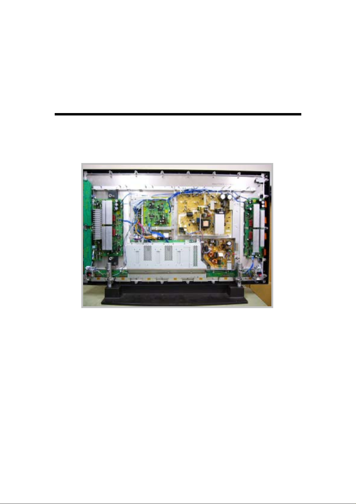
(TH-42PW7 Back View)
technology to produce vivid images as well as proprietary “Motion Pattern Noise
Reduction” (i.e. MPD) technology to eliminate most of motion picture
anomalies and artifacts which are a continuing problem with plasma display
panel TVs, the PEAKS make it possible to gain a 10% increase in brightness
along with a 10% decrease in power consumption.
1
Page 2
1. New Feature
1-1. Structure of New PEAKS System
To realize the high picture quality in Hi-Vision broadcasting, a large size screen, we,
Panasonic have originally developed the necessity plasma panel, panel driver, digital
processing LSI. The total system achieved the high picture quality names a Picture
Enhancement Accelerator with Kinetic System so calls the “PEAKS”. This time the PEAKS
improved moreover its feature and finally “New PEAKS” developed for introduction of the 7
series plasma TV. The new PEAKS proceeds video signal in full-digital and make it possible
to deal with the video signal with no degradation and high picture quality. As can be seen in
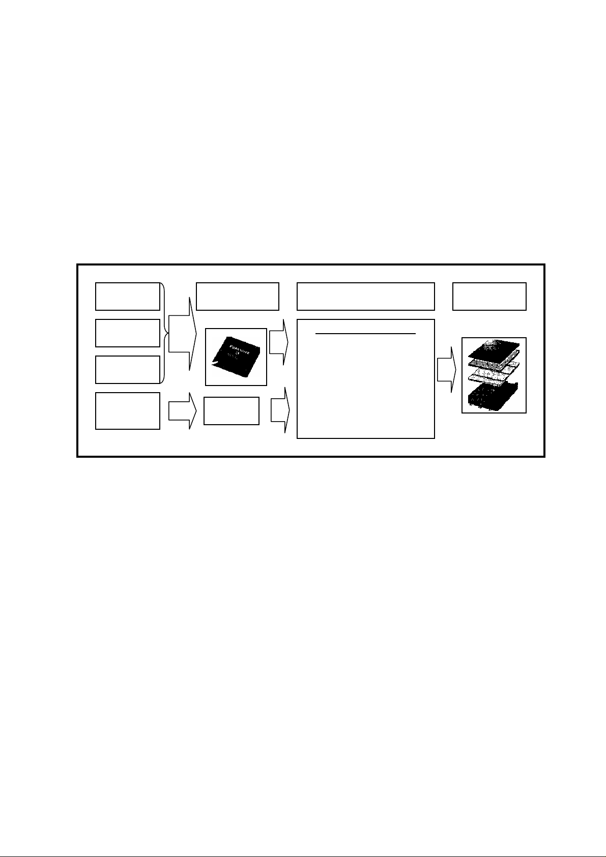
Figure 1, this shows high picture quality system New “PEAKS”
Digital Tuner
PEAKS Processor
Plasma PEAKS Driver Panel PEAKS
SD Card
High Picture Quality Control
*New Advanced Real Gamma
HDMI
*Vivid Colour Creation
*Sub Pixel Enhancer
Analogue
Video
A/D CONV
*Motion Pattern Noise Reduction
*Real Black Creation
Plasma Panel
Figure 1 High Picture Quality System New “PEAKS”
1-2. Plasma PEAKS Driver
A large size screen had the visual presence, reproduction of motion picture are the major
features for plasma TV. The new developed PEAKS driver has improved moreover those
features and newly employed the following five functions.
1) New Advanced Real Gamma
2) Vivid Colour Creation (= Colour Management)
3) Sub Pixel Enhancer
4) Motion Patter Noise Reduction (MPD)
5) Real Black Creation
2
Page 3
g
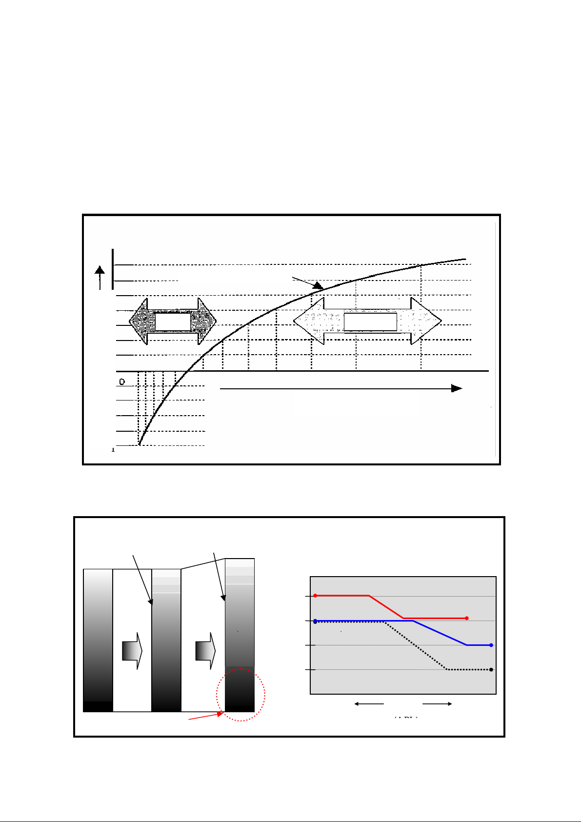
1-2-1. NEW Advanced Real Gamma
As can be seen in figure 2, the human sight senses the minimum variation of brightness at
especially dark picture, and therefore it’s necessary for a fine graduation at the dark scene
against the bright scene. The new advanced real gamma controls the sub-field in
accordance with scene, so that each pixel is controlled in fine and in addition the new
plasma panel allocates the fine graduation to the low luminance range and eventually total
2,048 graduations are reproduced by normal or cinema mode setting. By this technique, the
result of dark scene is dramatically enhanced image clarity with fine detail and realism.
Sight Characteristics
Minimum Unit for Sense of Si
Bright ness
Dim Bright
ht
Figure 2 Sense of Sight verse Brightness
Real Gamma Supper Real Gamma
Graduation
Brightness
Brightness
PHD7 Normal/Cinema
2048
1536
1024
PHD7 Dynamic
PHD6
768
512
Dark Bright
Dark compensates gradation step becomes 2/3 of other component.
Scene
(APL)
Figure 3 New Advanced Real Gamma
3
Page 4

1-2-2. Vivid Colour Creation
To have the colour presence, it’s necessary for following expression.
1) Deep blue colour (e.g. Sky, Deep Sea)
2) Flesh green colour (e.g. Trees & plants, forest)
3) Natural skin tones colour
In conventional technique, the two-dimensional (i.e. 2D) colour compensation was utilized
and it delivered an artificial skin tones and unbalance dark colour. The vivid colour creation
employs the three-dimensional (3D) colour management system is a new correction process
that works in 3D colour matrix (hue, brightness). By correcting hue and brightness
individually and providing finer control, this process delivers vibrant colours and natural skin
tones. (Note: For separate type plasma display monitor, the default setting for colour
management system is OFF)
2D Colour Space
Conventional
New
3D Colour Space
Luminance
Figure 4 Vivid Colour Creation
1-2-3. Sub Pixel Enhancer
Basically the plasma TV and LCD TV determine the picture resolution by number of panel
pixels. In conventional model, the three pairs of R, G, B dots make up one pixel and it deals
with one pixel units. The new sub pixel enhancer controls the R, G, B dots separately to
increase the picture sharpness at the high space frequency where the scene located in part
of finer picture and finally makes it possible to make the edge detail correction. By this
manner, the frequency range proceeded the video signal is expanded and the smooth hatch
line can be duplicated. E.g. fine art object, geometric pattern architecture can be clearly
displayed on the plasma screen. (Using sub pixel control, the resolution is increased about
30% from conventional technique)
4
Page 5

Conventional
New
1 pixel
(RGB) unit
1 dot
(Each RGB) unit
X3
Rough
Smoothnes
Figure 5 Sub Pixel Enhancer
1-2-4. Motion Pattern Noise Reduction
Generally the plasma TV has an advantage of displaying motion picture. However, when an
object had a specific gradation moves in specific speed, the motion pattern noise
disturbance (i.e. MPD) may occur at sub-field method. As can be seen in figure, this sees
the sub-field method & motion picture disturbance. In case of the sub-field method, if the
human eyes follow the motion object and the plasma emits the light of the adjacent
sub-fields in overlap, the human eyes can not sense the gradation in the brightness
accurately and eventually the motion pattern noise may appear on the display. We have
introduced the new motion pattern NR to the 7 series plasma TV. The new NR detects
motion pattern that tend to generate noise and makes the necessary adjustments to
maximize image quality. Finally it reduces MPD noise and realizes the crisp, clean moving
images.
Conventional
New
Figure 6 Motion Pattern Noise Reduction
5
Page 6

Figure 7 Sub-Field Method & Motion Picture Disturbance
12 Sub Field Liner Coding:60Hz System
Improve 50 Hz flicker with 1536 Graduation by new Quasi 100Hz
1 2 3 4 5 6 7 8 9 11 10 12
14 Sub Field QUASI 100 Hz System
1536
1024
768
Graduation
512
PHD7 Normal/Cinema
PHD7 Dynamic
PHD6
1 2 3 4 5 6 7 8 9 11 10 12 13 14
Dark Bright
Improved 50Hz flicker
Scene
(APL)
Figure 8 New 14 Sub-Field Quasi 100Hz Cording System
6
Page 7

1-2-5. Real Black Creation
The black is very important to express the visual image. Let explain the real black drive
system. The plasma TV emits a feeble light for pre-discharge when an image is black. By
reducing the pre-discharge emission, the new read black system provides deeper, richer
blacks and a stunning 4000:1 contrast. In addition, the deep black filter has been introduced
to new plasma TV. The front protective glass of the plasma display panel incorporates a
deep black filter that suppresses light transmittance and slashed the industry’s highest level
of contrast when viewing in bright surrounding.
Real Black Drive Circuit
Deep Black Filter
1-3. PEAKS Panel
The PEAKS panel improves the light-emitting efficiency & intensity and reduces the loss of
Contrast 3000:1
driver circuit. By improving this, the light-emitting efficiency is increased by about 20%. As a
result, the peak brightness is boosted by 10% as compared with previous model. In the
meantime, the power consumption is reduced by about 10%.
Incoming Light Source
Reduction of reflection
Front Protect
Black Glass
Figure 9 Real Black Creation
1-3. PEAKS Panel
The PEAKS panel improves the light-emitting efficiency & intensity and reduces the loss of
driver circuit. By improving this, the light-emitting efficiency is increased by about 20%. As a
result, the peak brightness is boosted by 10% as compared with previous model. In the
meantime, the power consumption is reduced by about 10%.
Conventional rib structure (strip-type ribs)
Step-formed box barrier rib structure
Figure 10 PEAKS Plasma Panel
7
Page 8

2. Electrical Circuit Explanation
2-1. Power Circuit
The power circuit is mainly composed of PF and P boards. Using technique of the switching
regulator, this circuit provides the stable voltage to plasma circuit.
As can be seen in figure10, the AC voltage is supplied to EMI
circuit on the PF board. This circuit blocks the EMC
interference to not be fed outside through the AC cord
because the product complies with EMC standard.
After that, the AC voltage is fed to two paths,
One is fed to primary power circuit on the P board and the other is fed to stand-by voltage
regulator inside of PF board for supplying DC power to the optional function boards.
2-1-1. PF Circuit
As can be seen in figure 11, this PF circuit consists of the switching regulator and it controls
the secondary voltage in accord with secondary load and primary flow current. To begin with,
the input AC voltage is fed to D910 for rectification, T920 for switching transformer and to
SW transistor via 1 pin of IC910. The primary coil of T910 induces the voltage at secondary
coil and finally generates the DC voltage for farther P, J boards. In parallel, the power circuit
controls the output voltage by using two protections, over current protection and over load
protection. When the load of secondary output is increase, the over load detect feeds the
low voltage to VCO and it increases the oscillation frequency. The increase of switching in
the primary coil induces the high energy at secondary coil and it finally make up for an over
load. In the meantime, when an over current flows in the primary coil, the high DC voltage
after rectifier is feed to the VCO and it decreases the frequency. Finally the decrease of
EMC Coil
switching reduces the current in primary coil for current stabilization.
2-1-2. PF SOS Detect Circuit
This circuit detects power abnormality on the slot, PF boards due to causing the short circuit.
In fact the power is fed to the slot board when placing the TV set in the stand-by mode.
Therefore it detects power abnormality on the PF board as well during stand-by mode.
When detecting the PF abnormality, the u-COM controls the primary po wer and finally stops
the slot power supply. In the same timing, u-CON controls the LED RED blinks 10 times.
(Simplified block diagram is shown in figure 13)
8
 Loading...