

Panasonic GP6DU, GPH6DU, GPH7D Training Manual
Technical Guide
Plasma Training Course
GP6DU, GPH6DU, and GPH7D (Onyx)
Chassis
Troubleshooting
Panasonic Services Company
National Training

A
y
Prepared by
César Perdomo & Jean Magloire
Panasonic Services Company
National Training
"HDMI, the HDMI logo and High-Definition Multimedia Interface are trademarks or registered trademarks of HDMI Licensing LLC."
BBE, the BBE logo, Sonic Maximizer and High Definition Sound are registered trademarks or trademarks of BBE Sound, Inc.
Copyright © 2005 by Panasonic Services Company
ll rights reserved. Unauthorized copying and distribution is a violation of law.
Warning
This service information is designed for experienced repair technicians only and is not designed for use b
the general public. It does not contain warnings or cautions to advise non-technical individuals of potential
dangers in attempting to service a product. Products powered by electricity should be serviced or repaired
only by experienced professional technicians. Any attempt to service or repair the product or products
dealt with in this service information by anyone else could result in serious injury or death.

Table of Contents
Introduction.........................................................................................................1
Model Line Up .....................................................................................................3
New Features and Circuit Improvements .........................................................5
Boards Layout.....................................................................................................9
TH-42PD25U Boards Layout (GP6DU)...............................................................9
TH-42PX25U Boards Layout (GPH6DU)............................................................ 9
TH-50PX25U Boards Layout (GPH6DU)..........................................................10
TH-42XVS30 (Onyx) Boards Layout (GPH7D).................................................10
TH-50XVS30 (Onyx) Boards Layout (GPH7D).................................................11
TH-65XVS30 (Onyx) Boards Layout (GPH7D).................................................11
Video Block .......................................................................................................13
GP6DU and GPH6DU Chassis..........................................................................13
GPH7D (Onyx)...................................................................................................21
ONYX J Board Video Selector......................................................................21
ONYX J Board Sync Selector.......................................................................22
ONYX DR Board Block Diagram...................................................................23
Onyx RGB/Sync Analog to Digital Conversion...........................................25
Onyx Data Drive Operation...........................................................................26
GPH7D (Onyx) Tuner Receiver ........................................................................27
Photo Viewer..................................................................................................28
Power-on Operation..........................................................................................29
Power-on Operation (TH-42PD25U)................................................................. 29
TH-42PD25U-P Standby Circuit....................................................................29
TH-42PD25U-P Power-On with Switch on the Front Panel ........................29
TH-42PD25U-P Power-On with Remote Control .........................................30
Power On Operation (TH-42PX25U).................................................................35
TH-42PX25U-P CPU Requirements and Standby Circuit. ..........................35
TH-42PX25U-P Power-On with Switch on Front Panel...............................38

TH-42PX25U-P Power-On with Remote Control..........................................38
Power-on Operation (TH-65XVS30U)...............................................................41
Power-On with Switch on Front Panel.........................................................41
Power-On with Remote Control ...................................................................42
Protection Circuits............................................................................................45
TH-42PD25U-P Protection Circuits..................................................................45
TH-42PD25U PA board SOS detect..............................................................47
TH-42PD25U 3.3V SOS detect ......................................................................51
TH-42PD25U SC and SS SOS Detect ...........................................................52
Troubleshooting chart for the TH-42PD25U ...................................................57
Power LED blinks 2 Times............................................................................57
Power LED blinks 3 Times............................................................................58
Power LED blinks 4 Times............................................................................59
Power LED blinks 5 Times............................................................................60
Power LED blinks 7 Times............................................................................61
Power LED blinks 9 Times............................................................................62
Power LED blinks 12 Times..........................................................................63
SOS Troubleshooting (TH-42PX20U) ..............................................................65
Troubleshooting chart for the TH-42PX20U ...................................................69
Power LED blinks 2 Times............................................................................69
Power LED blinks 3 Times............................................................................70
Power LED blinks 4 Times............................................................................71
Power LED blinks 5 Times............................................................................72
Power LED blinks 7 Times............................................................................73
Power LED blinks 9 Times............................................................................74
Power LED blinks 12 Times..........................................................................75
Power LED blinks 13 Times..........................................................................76
TH-42PX25U-P Protection Circuits..................................................................77
TH-42PX25U PA board SOS detect..............................................................79
TH-42PX25U 3.3V SOS detect.......................................................................80
TH-42PX25U 5V SOS Detect Circuit (D board)............................................80
TH-42PX25U SC and SS SOS Detect ...........................................................82
TH-42XVS30 Protection Circuits..................................................................85
TH-42XVS30 3.3V SOS Detect circuit (D board)..........................................87
TH-42XVS30 5V SOS Detect Circuit (D board)............................................87
TH-42XVS30 SC and SS SOS Detect............................................................90
TH-42XVS30 Tuner SOS Detect....................................................................92
TH-42XVS30 Power SOS Detect...................................................................93
TH-42XVS30 Fan SOS Detect .......................................................................93

Troubleshooting chart for the TH-42XVS30....................................................99
Power LED blinks 2 Times............................................................................99
Power LED blinks 3 Times..........................................................................100
Power LED blinks 4 Times..........................................................................101
Power LED blinks 5 Times..........................................................................102
Power LED blinks 7 Times..........................................................................102
Power LED blinks 7 Times..........................................................................103
Power LED blinks 9 Times..........................................................................104
Power LED blinks 12 Times........................................................................105
Service Notes..................................................................................................107
TH-37PA20U TH-42PA20U (Service Hint SH-B19-04-06)..............................107
TH-37PA20U TH-42PA20U (Service Bulletin # SB-B19-04-01).....................108
IC551 Failure................................................................................................108
TH-37PD25U, TH-37PX25U, TH-42PD25U, TH-42PX25U, and TH50PX25U.109
Heat Transfer Pads for Models Number: TH-37PD25U, TH-37PX25U, TH-
42PD25U, TH-42PX25U, and TH50PX25U..................................................109
Corrupted EEPROM data in the 480i addressing area for Models Number:
TH-37PD25U, TH-37PX25U, TH-42PD25U, TH-42PX25U, and TH-50PX25U
(Service Bulletin SB-B19-04-12).................................................................110
TH-37PX25U, TH-42PX25U, TH-50PX25U......................................................113
Remedy to reduce the rattle noise from speaker. ....................................113
TH-42XVS30 (onyx).........................................................................................113
Information about the speakers.................................................................113
Alignment Procedures....................................................................................114
Pedestal Setting ..........................................................................................114
NTSC White Balance Adjustment ..............................................................115
HD Panel White Balance Adjustment ........................................................116
Sub Brightness Setting...............................................................................117
Hotel Mode Operation.................................................................................118
Entry to Hotel Mode...................................................................................118


Introduction
This technical guide was prepared with the following objectives in mind:
• Provide the servicer with a brief overview of the concepts of operation for new
circuits employed in this line of Plasma models.
• Provide drawings with emphasis on signal path to simplify the task of signal
tracing and to locate the cause of a defect.
• Furnish troubleshooting procedures that contribute to a speedy repair of the
product.
• Provide examples of typical problems that may have occurred in similar types
of circuits.
1

2
Model Line Up
TH-37PD25U
37-inch 480p Version
2 Component Video Inputs
3 Composite Video Inputs
3 S-Video Inputs
1 HDMI / HDCP input
1 Tuner _NTSC/ATSC/QAM (SDTV and
HDTV broadcasts) (Cable CARD Ready)
1 Tuner_ NTSC (Standard analog
broadcasts for PIP)
PC / SD Card Inputs
Integrated Speaker System
Surround Sound
TH-37PX25U
37-inch 480p/1080i Version (720p PC Only)
2 Component Video Inputs
3 Composite Video Inputs
3 S-Video Inputs
1 HDMI / HDCP input
1 Tuner _NTSC/ATSC/QAM (SDTV and
HDTV broadcasts) (Cable CARD Ready)
1 Tuner_ NTSC (Standard analog broadcasts
for PIP)
PC / SD Card Inputs
Integrated Speaker System
Surround Sound
TH-42PD25U
42-inch EDTV Version
2 Component Video Inputs
3 Composite Video Inputs
3 S-Video Inputs
1 HDMI / HDCP input
1 Tuner _NTSC/ATSC/QAM (SDTV and
HDTV broadcasts) (Cable CARD Ready)
1 Tuner_ NTSC (Standard analog
broadcasts for PIP)
PC / SD Card Inputs
Integrated Speaker System
Surround Sound
TH-42PX25U
42-inch 480p/1080i Version (720P PC Only)
2 Component Video Inputs
3 Composite Video Inputs
3 S-Video Inputs
1 HDMI / HDCP input
1 Tuner _NTSC/ATSC/QAM (SDTV and
HDTV broadcasts) (Cable CARD Ready)
1 Tuner_ NTSC (Standard analog broadcasts
for PIP)
PC / SD Card Inputs
Integrated Speaker System
Surround Sound
3
TH-42XVS30UP
42-inch HD Version (720p via PC input
only)
Digital Multimedia Receiver
2 Component Video Inputs
3 Composite Video Inputs
3 S-Video Inputs
1 HDMI / HDCP input
1 Tuner _NTSC/ATSC/QAM (SDTV and
HDTV broadcasts) (Cable CARD Ready)
1 Tuner_ NTSC (Standard analog
broadcasts for PIP)
PC / SD Card Inputs
Integrated Speaker System
Surround Sound
TH-50XVS30UP
50-inch HD Version (720p via PC input only)
Digital Multimedia Receiver
2 Component Video Inputs
3 Composite Video Inputs
3 S-Video Inputs
1 HDMI / HDCP input
1 Tuner _NTSC/ATSC/QAM (SDTV and
HDTV broadcasts) (Cable CARD Ready)
1 Tuner_ NTSC (Standard analog broadcasts
for PIP)
PC / SD Card Inputs
Integrated Speaker System
Surround Sound
TH-65XVS30UP
65-inch HD Version (720p via PC input only)
2 Component Video Inputs
3 Composite Video Inputs
3 S-Video Inputs
1 HDMI / HDCP input
1 Tuner _NTSC/ATSC/QAM (SDTV and HDTV broadcasts) (Cable CARD Ready)
1 Tuner_ NTSC (Standard analog broadcasts for PIP)
PC / SD Card Inputs
Integrated Speaker System
Surround Sound
4

New Features and Circuit Improvements
Dedicated media receiver
• Built-In NTSC Tuner
• Built-In ATSC Tuner
• Built-In QAM Tuner
• Cable-Card Ready
• BBE VIVA HD 3D
• AI Sound Control
• 3 A/V Input (Composite or S-Video)
• 2 Component Video Inputs
• PC Input (VGA/SVGA/XGA/UXGA)
• Digital Audio Out
• On/Off Timers
• SD Card Slot with Photo Viewer
• HDMI Input
• 2 Tuners (PIP with Split Screen) Handle ATSC/QAM/Cable-CARD tuning,
source A/V switching and SD/PC Card connectivity
• Approximately 21 feet cable connects receiver to Plasma set. It doesn’t need
to be close to components
Long Life Expectancy
• Up to 60,000 hours comparable to CRT
• Over 25 years. (Based on approximately 6 hours a day, 365 days per year
equals 27.4 years)
Burn-In Resistance
• Reformulated phosphors utilized
• Aging occurs much more slowly
8.58 Billion Colors via Improved Super Real Gamma
• 2,048 shades of gradations
• 8.58 billion colors
• Color reproduction more faithful to true life
Digital Access Pack (Digital Tuning System)
• Integrated ATSC and QAM tuners
• NTSC tuner
• Cable Card provides subscription cable channels without box
• No external tuners needed for HD, cable, digital cable or HD cable
• Customer gets true plug and play HD/ Cable TV
5

Color Purity Optimizer
• Works in 3 dimensions brightness, color and hue
• Precision control for vibrant colors
• Vibrant colors will stand out better while skin tones will remain natural
Motion Pattern Noise Reduction
• New technology detects patterns that generate noise
• Circuit employs countermeasures to maximize image quality
• Image will be smoother and more natural with all sources.
New Sub-Pixel Controller
• Handles contour correction at sub-pixel level
• Greatly improves control precision of image
• Diagonal lines will appear sharp and straight (Compare diagonal lines on
Onyx XVS sets to other).
6
Models Comparison Tables
Cable
Native
Model Chassis
TH-50PX25U/P GPH6DU 1366x768 Yes 1536 Up to 3000:1
TH-42PX25U/P GPH6DU 1024x768 Yes 1536 Up to 3000:1
TH-37PX25U/P GPH6DU 1024x720 Yes 1536 Up to 3000:1
TH-42PD25U/P GP6DU 852x480 Yes 1536 Up to 4000:1
TH-37PD25U/P GP6DU 852x480 Yes 1536 Up to 4000:1
Resolution
(Number of
pixels)
CARD
1
Ready
service
without the
cable
box
Shades of
Gradation
Contrast
Ratio
TH-42XVS30
TH-50XVS30
TH-65XVS30
TH-50PHW7BX GPH7D2 1366x768 Yes 1536 Up to 3000:1
GPH7D
Onyx
GPH7D
Onyx
GPH7D
Onyx
1024x768 Yes 1536 Up to 3000:1
1366x768 Yes 1536 Up to 3000:1
1366x768 Yes 1536 Up to 3000:1
Table 1
7

8
Boards Layout
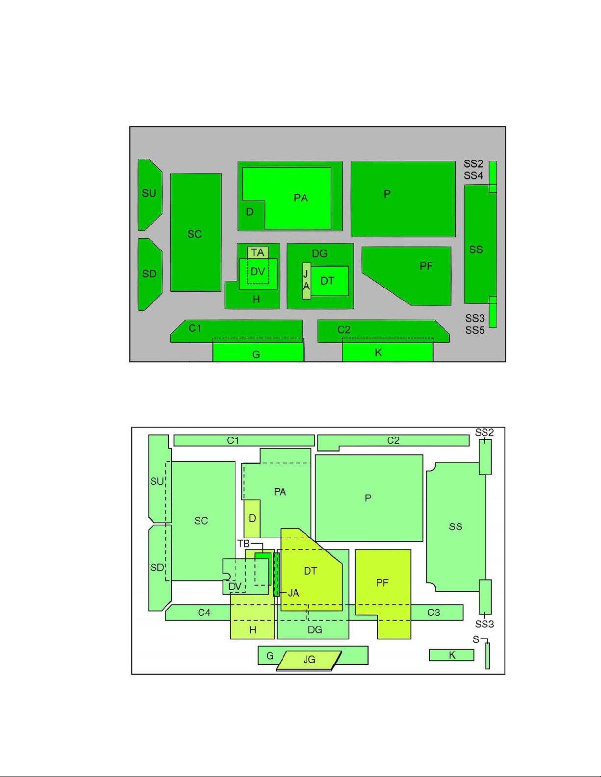
TH-42PD25U Boards Layout (GP6DU)
Figure 1 - TH-42PD25U boards layout
TH-42PX25U Boards Layout (GPH6DU)
Figure 2 - TH-42PX25U boards layout
9
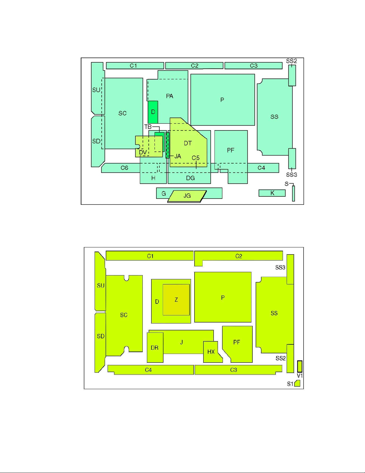
TH-50PX25U Boards Layout (GPH6DU)
Figure 3 - TH-50PX25U boards layout
TH-42XVS30 (Onyx) Boards Layout (GPH7D)
Figure 4 - TH-42XVS30 Board Layout
10
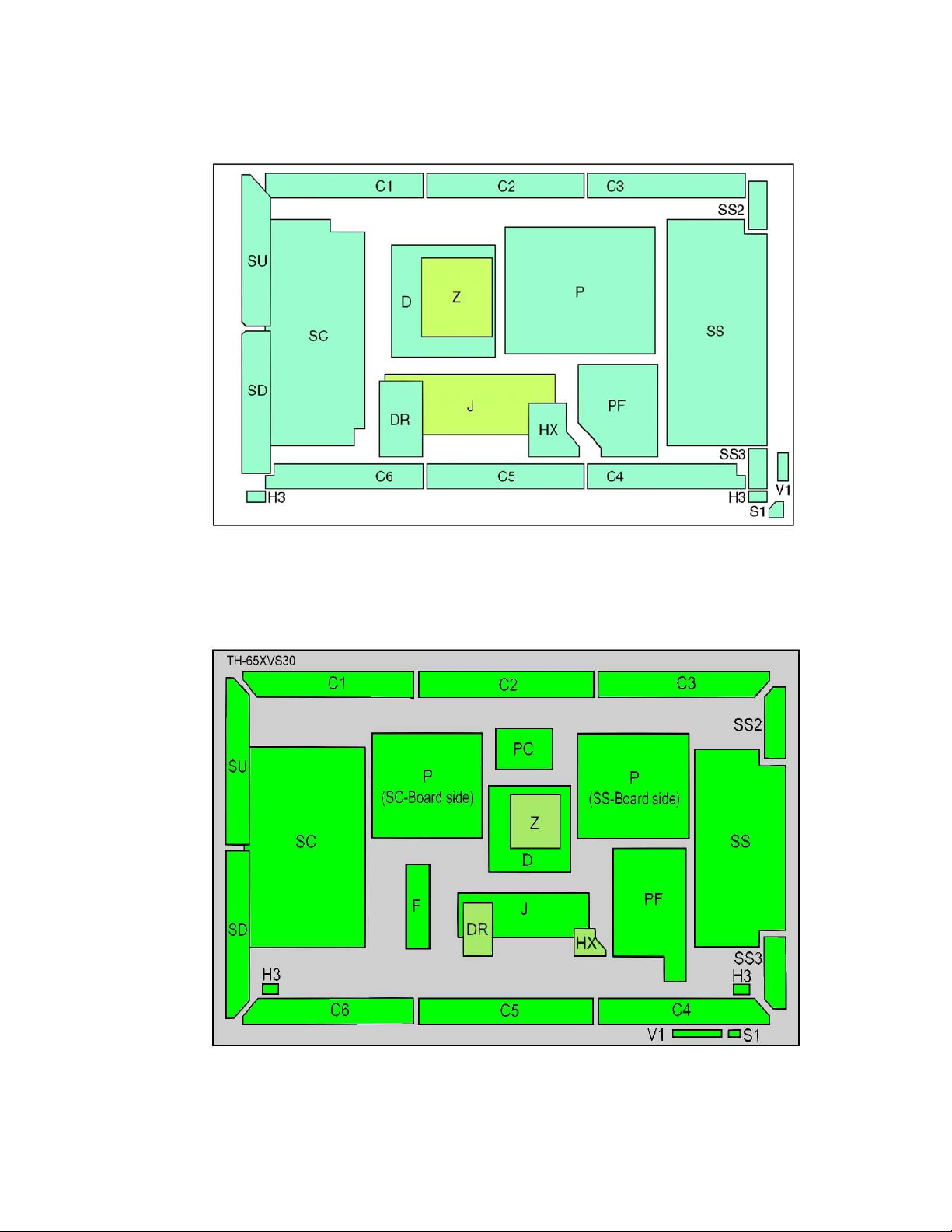
TH-50XVS30 (Onyx) Boards Layout (GPH7D)
Figure 5 - TH50XVS30 Board Layout
TH-65XVS30 (Onyx) Boards Layout (GPH7D)
Figure 6 - TH65XVS30 Board Layout
11

12

Video Block
GP6DU and GPH6DU Chassis
The GPH6DU, and the GP6DU series plasma panels incorporate two tuners. The
main Digital Tuning System is used for primary picture operation. It provides
component and composite video and audio output signals from its ATSC, NTSC,
and QAM tuners. An additional NTSC sub-tuner provides a video output signal
(no audio) for use with multi-picture functions.
The composite output of the main tuner is connected to the NTSC input switch IC
on the H Board. The component output is connected to the main switch IC on the
H board. The unit also contains three video inputs that are also connected to the
input switch IC. The input switch IC selects one video signal from 5 video inputs
for main picture operation and another for sub-picture operation. Selection is
controlled by the MPU via the I
connected to the main switch IC.
The panel also contains two component inputs and an HDMI input. The inputs
are connected to the main switch. The HDMI input connector on the DG Board,
accepts signals to HDMI receiver where it undergoes serial to parallel
conversion. The output of the receiver is then converted to “Y, Pb, Pr” component
signals before being applied to the Main switch. The MPU selects one of the 8
inputs for main picture operation and another for sub-picture operation.
On the DG- Board, the global core IC (GC2M) converts the composite video
signal of the main picture to RGB video signals. The GC2S IC processes the
sub-picture information and combines it with the main picture. It performs
interlace to progressive scan conversion. The Global core IC also converts the
horizontal frequency of all NTSC input-signals to 31.468KHz. The output of the
GC2M IC is RGB, which is applied to an RGB amplifier.
IC001 is the TV Main CPU. It generates the On-Screen Display (OSD) RGB
signals, which are applied to the RGB amplifier stage. A switching circuit
combines the two sets of RGB signals for display on the screen. All NTSC,
Component, and RGB picture adjustments such as picture, tint, color, brightness,
etc. are performed inside this IC.
The RGB/PC select circuit switches between PC and all other inputs. The output
of the switch is routed to the D-Board.
2
C Bus (SDA & SCL). These two outputs are then
13
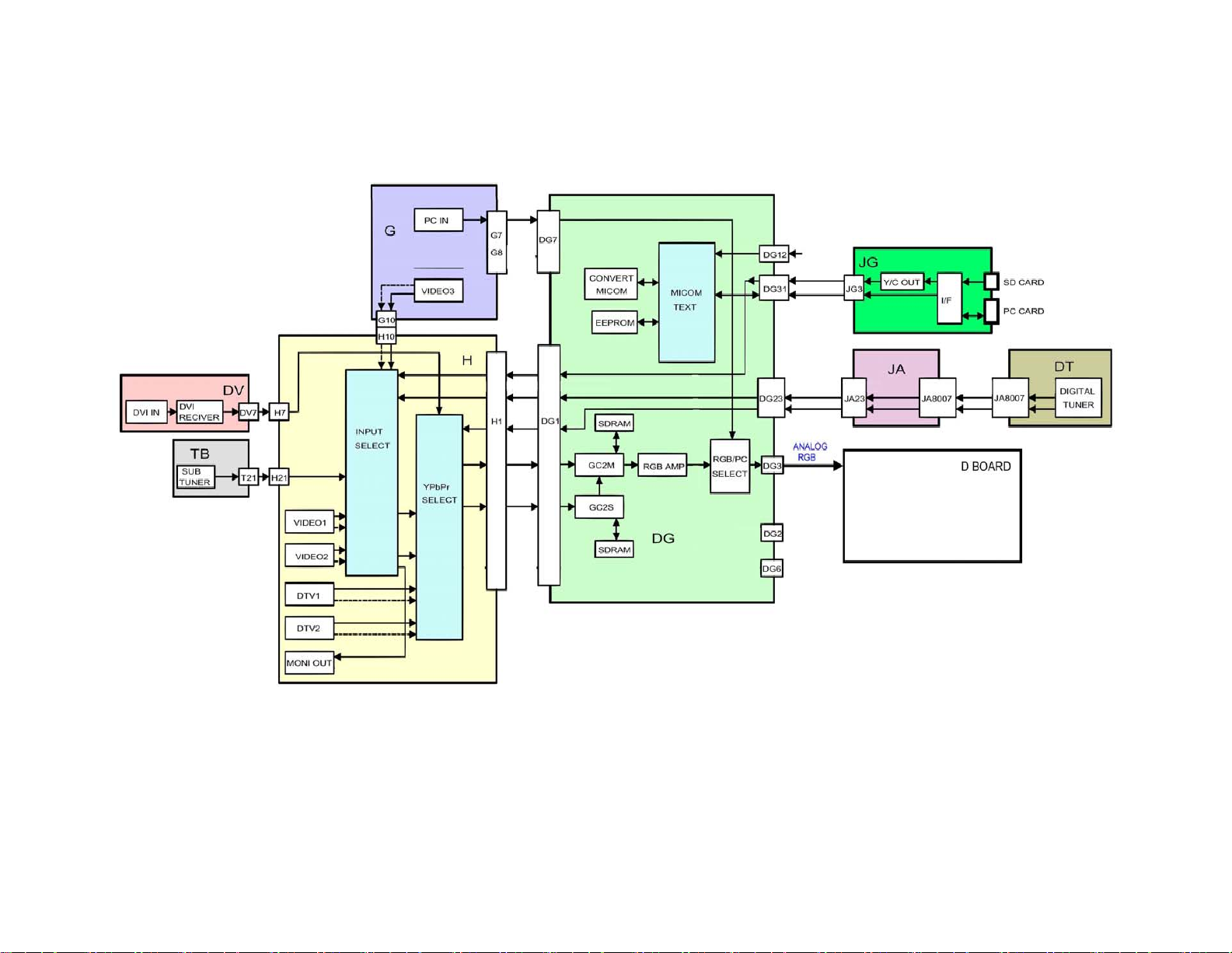
Figure 7 - Video Block Diagram
14
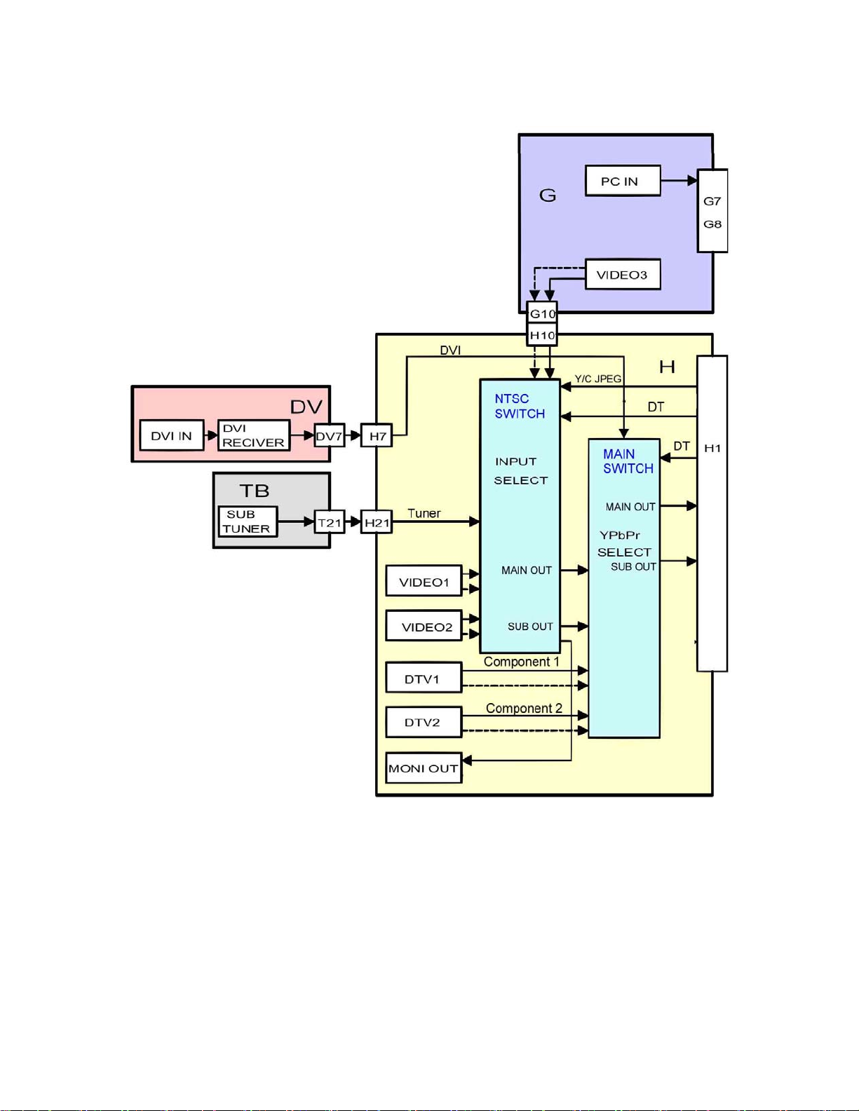
Figure 8 - H Board Block Diagram
15

16
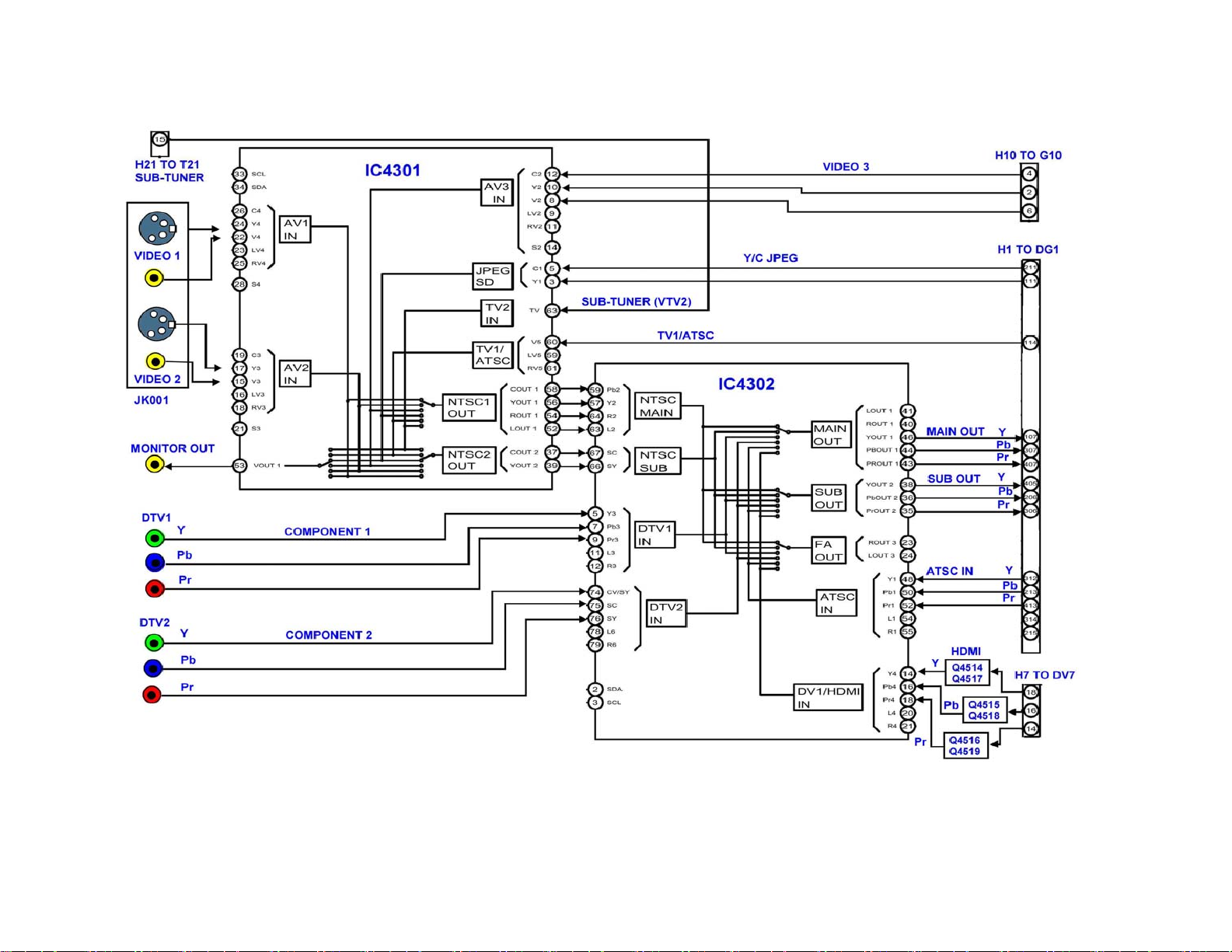
Figure 9 - H Board Block Diagram
17
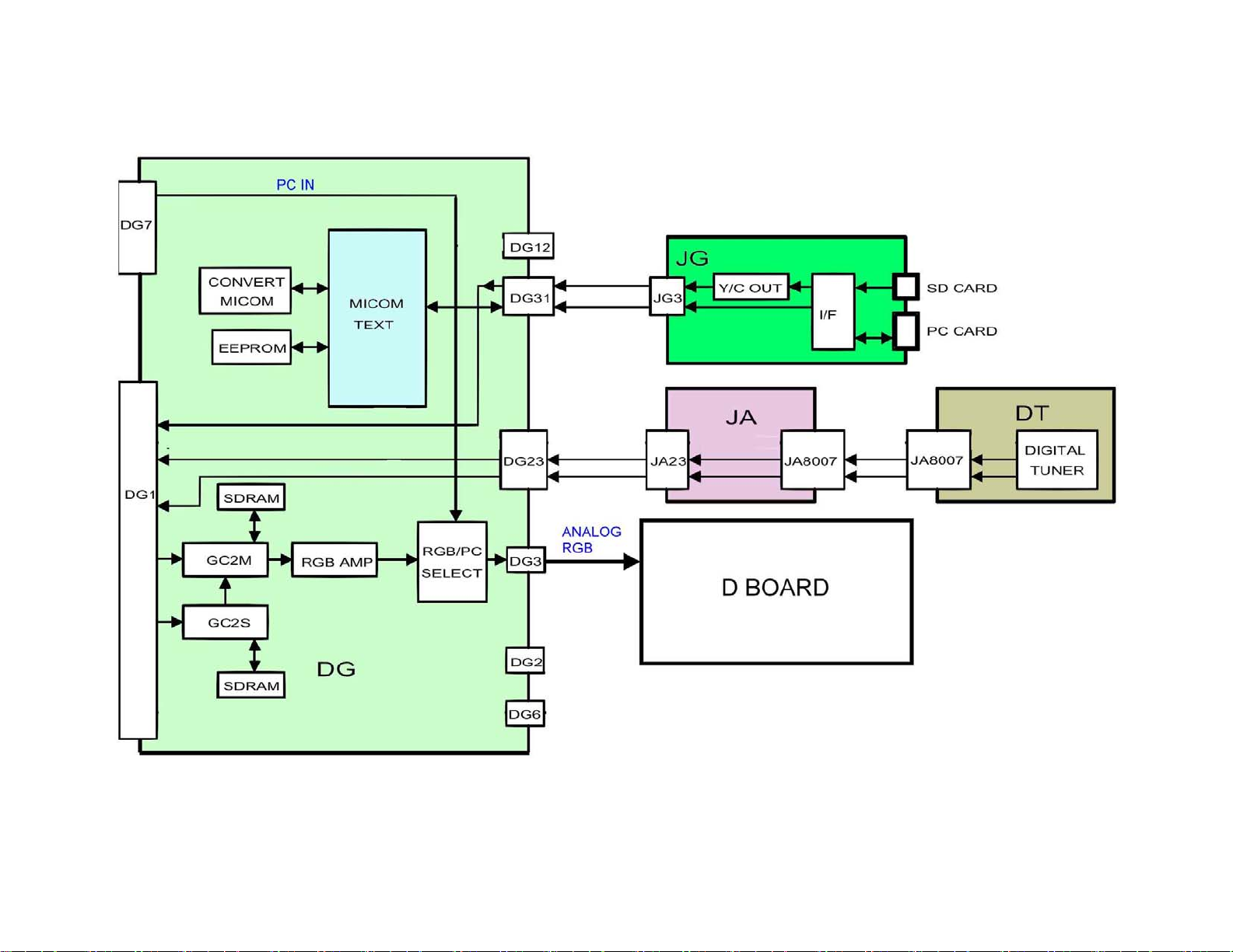
Figure 10 - DG Board Block Diagram
18
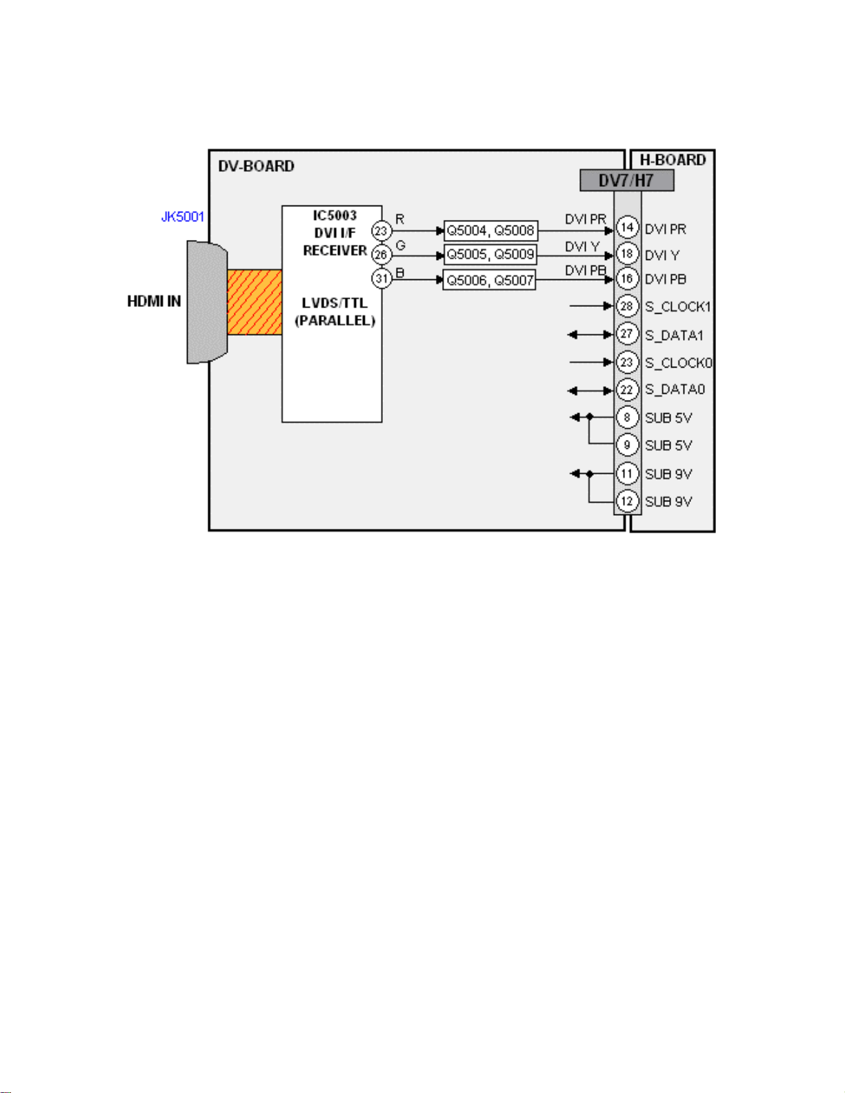
GPH6DU Chassis HDMI Signal Process
Figure 11 - HDMI Signal Process
The HDMI (High Definition Multimedia Interface) input is a port designed to receive
digital video and audio from a set-top box, a DVD player, or other digital devices.
IC5003 of the DV board converts the digital video to parallel analog Y, Pb, and Pr video
signals. The signals are output from IC5003 to a set of video amplifiers. After
amplification, the signals are applied to the A-Board via pins 14, 16, and 18 of the
connector DV7/DG51.
Note: To connect an external device that has a DVI output to a plasma panel model that
has an HDMI input only, use an adaptor cable and connect the Audio signal to the
Audio jacks located below the HDMI input. An HDMI-DVI conversion cable (TYSCH03DH) is available from Panasonic parts department.
19
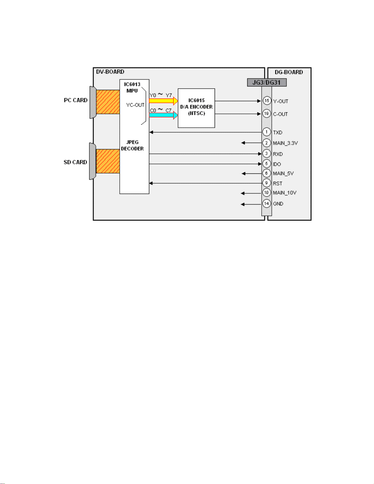
GPH6DU Chassis Photo Viewer Signal Process
Figure 12 - Photo Viewer Signal Process
Images from a SD or PCMCIA card, inserted into the Photo Viewer card slot, are
transferred to the DV-Board. After buffering, the JPEG information is decoded by
IC6013 and converted to luminance and chrominance data. The digital video output of
IC6013 is then converted to analog by IC6015 and output to the DG-Board via the
connector JG3/DG31. On the DG-Board, the luminance and chrominance photo viewer
information is selected and processed as for any other video input.
20
GPH7D (Onyx)
ONYX J Board Video Selector
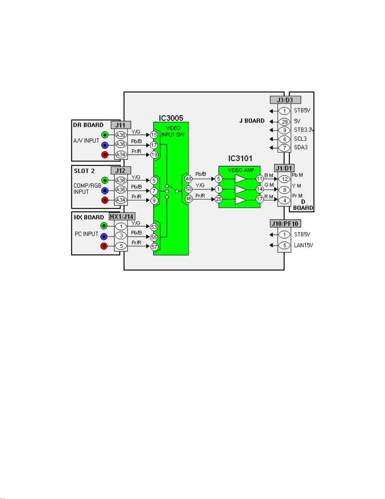
Figure 13 - J Board Video Selector
Onyx plasma panel models incorporate three video inputs. IC3005 selects between “Y,
Pb, Pr” and RGB signals that are output by the DR, Slot-2, and HX boards. The “Y, Pb,
Pr” or RGB signals output by IC3005 are amplified by IC3101 and applied to the Dboard via pins 4, 8, and 12 of the connector J1/D1.
21
ONYX J Board Sync Selector
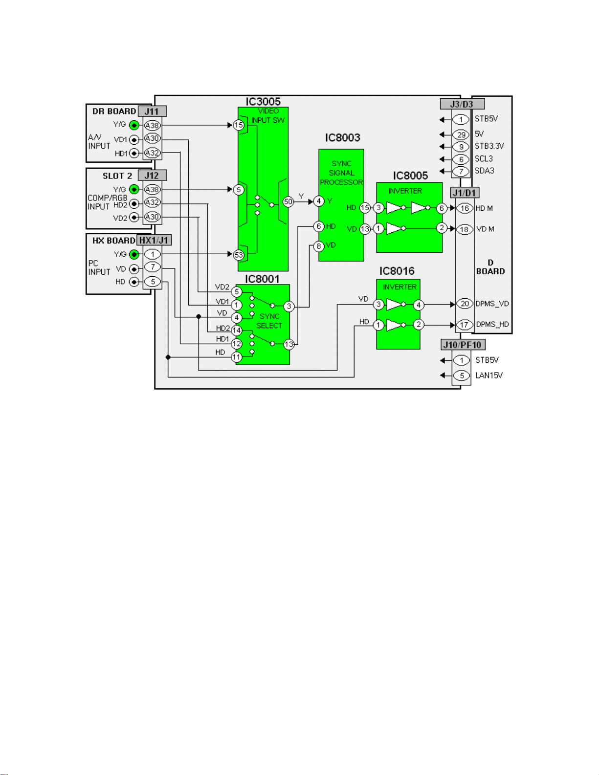
Figure 14 - J Board Sync Selector
RGB/PC Input Mode
The vertical and horizontal sync signals of the input video signals are applied via
connector J11, J12 or HX1 to the Sync selector IC, IC8001. The selected vertical and
horizontal sync signals are then output to the sync processor IC, IC8003. The signals
from IC8003 are applied to IC8005 for wave shaping and inversion. The vertical and
horizontal sync signals exit the J-board and enter the D-board via pins 16 and 18 of the
connector J1/D1.
The horizontal and vertical drive signals of the HX board (PC input) are inverted by
IC8016 and output to the D-board via pins 17 and 20 of the connector J1/D1.
Composite/ Component Video Input mode
The luminance (Y or G) signals are applied to an input switch (IC3005). The selected
Sync signals output by IC3005 are applied to the sync processor circuit (IC8003). The
horizontal and vertical pulses are separated from the Y or green signal and supplied to
IC8005 for wave shaping and inversion. The sync signals are then output to the Dboard via pins 16 and 18 of the connector J1/D1.
22
ONYX DR Board Block Diagram
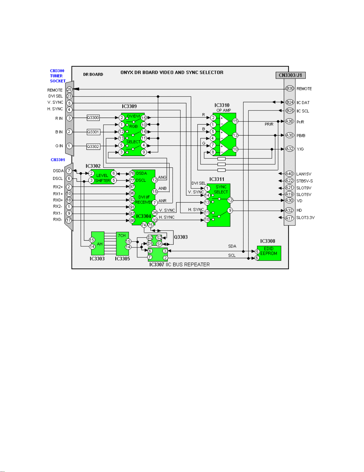
Figure 15 - DR Board Block Diagram
RGB signals output by the receiver box are input to the DR board via pins 1, 2, and 3 of
the socket CN3300. Upon entry to the DR-board, these signals are buffered by the
transistors Q3300, Q3301, and Q3302 and then output to IC3309 for video input
selection.
Video signals, from the receiver box, are also applied via the connector CN3301, which
resembles a DVI connector, and then to IC3304 for decoding into analog RGB. The
RGB signals are applied to pins 1, 3, and 13 of the selector IC, IC3309. The selected
RGB signals are output via pins 4, 14, and 15. The signals are then amplified by IC3310
and output to the J-Board via pins A30, A32, and A38 of the connector CN3303/J1.
Serial clock and data from the receiver box are applied via pins 6 and 7 of the video
connector CN3301 to the level shifter IC, IC3302. This IC reformats the DC and signal
levels of the clock and data pulses so that they match the specifications of IC3304 on
the DR-board. These pulses are then applied to IC3304.
23

CN3301, a connector that resembles a DVI port, is designed to receive digital video
from the receiver box. The HDCP (High-bandwidth Digital Content Protection) circuit
monitors the applied signals for copyright protection. Serial data that originates in the
receiver box is converted to parallel by IC3303, and back to serial by IC3305. This is
done to remove noise that may have been introduced into the long cable that connects
the receiver box and the display unit.
Clock and data output by IC3305 are applied to an I
2
C bus repeater circuit (IC3307)
before being applied to the EEPROM IC3308. The EEPROM contains the HDCP keys
used to block or allow the display of the content of a particular program. Data
communication is bi-directional allowing a complete handshake to take place before a
program is viewed.
The DR-board also performs sync selection of the input signals. Horizontal and vertical
sync of the tuner socket are directly connected to the sync select IC, IC3311. Sync
signals of the video input port are retrieved by IC3304 and provided to IC3311. The
output of the sync select switch is applied to the J-board via pins A30 and A32 of the
connector CN3303/J1.
24
 Loading...