

Page 1
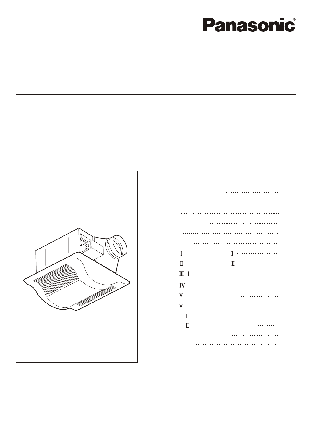
INSTALLATION INSTRUCTIONS
Ventilating Fan
Model No.
FV-05VFL3
FV-08VFL3
FV-11VFL3
Contents
General Safety lnformation
Description
Unpacking
Supplied Accessories
Dimensions
Wiring Diagram
lnstallation (Joist Mounting- )
lnstallation (Joist Mounting- )
lnstallation ( -Joist Mounting)
lnstallation (Between Joist Mounting )
lnstallation (Wooden Header )
lnstallation (ln Existing Construction )
Maintenance (Cleaning)
Maintenance (Replacement of Lamp)
Practical Guide to lnstallation
Specifications
Product Service
2-3
4
4
4
5
5
6-8
8-9
10
10-11
11-12
12
13
13-14
14
15
15
READ AND SAVE THESE INSTRUCTIONS
Thank you very much for having purchased our product.
Please read these instructions carefully before attempting to install, operate or service
the Panasonic product. Failure to comply with instructions could result in personal injury
or property damage. Please explain to users how to operate and maintain the product
after installation, and this booklet should be presented to users.
Please retain this booklet for future reference.
Page 2

GENERAL SAFETY INFORMATION
WARNING:
To reduce the risk of fire, electric shock or injury to persons, observe the following:
1. Use this unit only in the manner intended by the manufacturer. lf you have any questions, contact
the manufacturer.
2. Before servicing or cleaning unit, switch power off at service panel and lock the service
disconnecting means to prevent power from being switched on accidentally. When the service
disconnecting means cannot be locked, securely fasten a prominent warning device, such as a tag,
to the service panel.
3. Installation work and electrical wiring must be done by qualified person (s) in accordance with all
applicable codes and standards, including fire-rated construction.
4. Sufficient air is needed for proper combustion and exhausting of gases through the flue (chimney)
of fuel burning equipment to prevent back drafting. Follow the heating equipment manufacturer s
guideline and safety standards such as those published by the National Fire Protection Association
(NFPA), and the American Society for Heating, Refrigeration and Air Conditioning Engineers
(ASHRAE) and the local code authorities.
5. When cutting or drilling into wall or ceiling, do not damage electrical wiring and other hidden utilities.
6. Ducted fans must always be vented to the outdoors.
'
7. If this unit is to be installed over a tub or shower, it must be marked as appropriate for the
application and be connected to a GFCI (Ground Fault Circuit lnterrupter) - protected branch circuit.
8. These models are UL listed for tub and shower enclosures.
9. Do not use this fan with any solid-state speed control device.
10. Canada only: Not to be installed in a ceiling thermally insulated to a value greater than R40.
11. Do not disassemble the unit for reconstruction. lt may cause fire or electric shock.
12. A statement to the effect that when the product is to no longer be used, it must not be left in
place but removed, to prevent it from possibly falling.
13. Ceiling joist must be subjected to static load more than five times the weight of the product.
14 . The special-purpose or dedicated parts, such as mounting fixtures, must be used if such parts are
provided.
15. Do not install the product as the method which is not approved in the instruction.
16. This product must be properly grounded.
2
Page 3
GENERAL SAFETY INFORMATION CONTINUED
CAUTION:
1. Do not install this ventilating fan where interior room temperature may exceed 104 F (40 C).
2. Make sure that the electric service supply voltage is AC 120V, 60 Hz.
3. Follow all local electrical and safety codes, as well as the National Electrical Code (NEC) and the
Occupation Safety and Health Act (OSHA).
4. Always disconnect the power source before working on or near the fan, motor, light fixture or
junction box.
5. Protect the supply wiring from sharp edges, oil, grease, hot surfaces, chemicals or other objects.
6. Do not kink the supply wiring.
7. Provide make up air for proper ventilation.
8. For general ventilating use only. Do not use to exhaust hazardous or explosive materials and vapors.
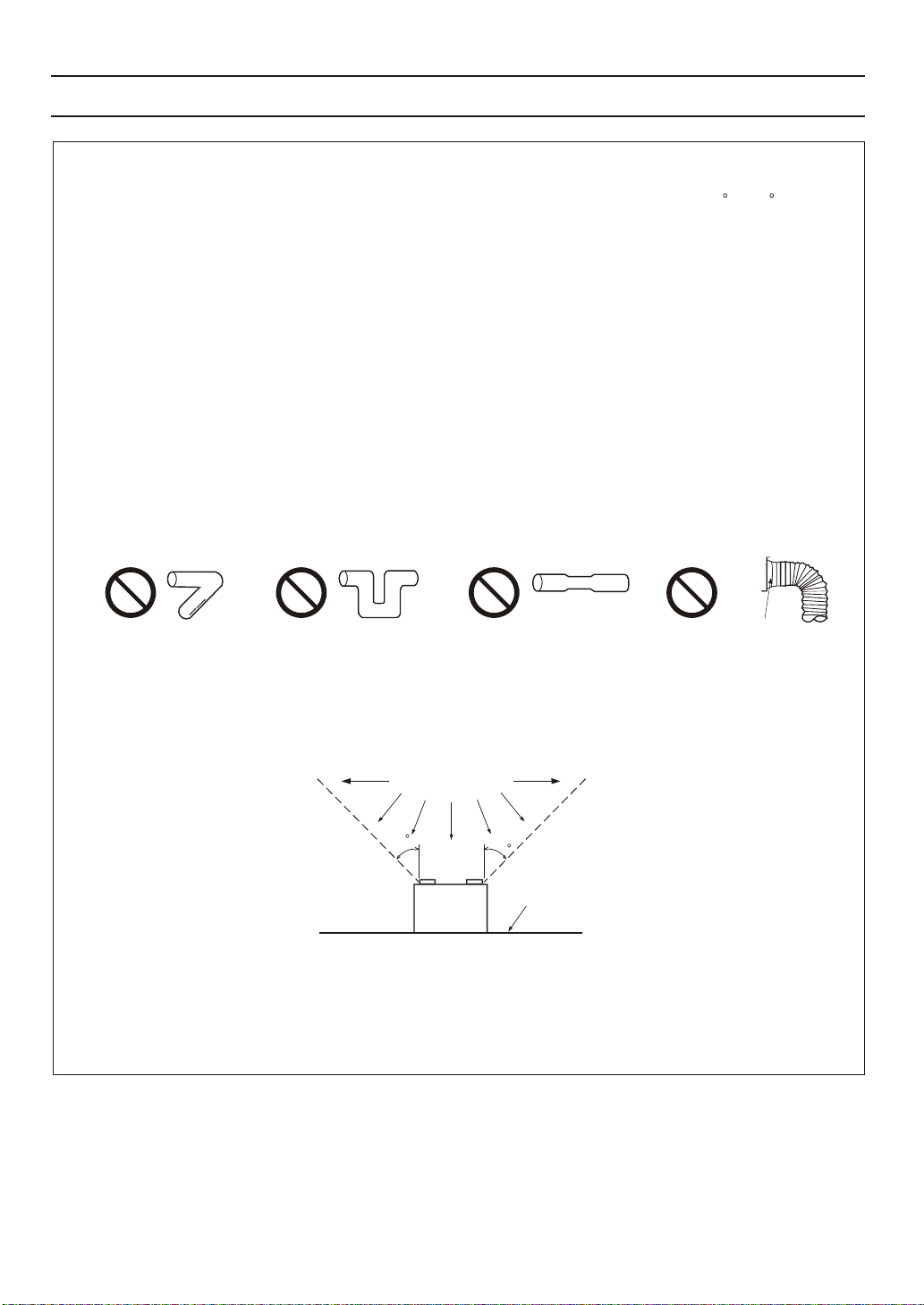
9. Do not install the unit where ducts are configured as shown in Fig. A.
Prohibition Prohibition Prohibition Prohibition
Adaptor
Fig. A
10. Not for use in cooking area. (Fig. B)
(Cooking area)
Do not install above or
inside this area
45
Cooking
equipment
45
Floor
Fig. B
11. USA only: This product has a fluorescent lamp that contains mercury. Disposal may be regulated in
your community due to environmental considerations. For disposal or recycling information, please
contact your local authorities or visit Panasonic website: http://www.panasonic.com/enveronmental
or call 1-888-769-0149.
3
Page 4
DESCRIPTION
These products are listed by UL under UL file No. E78414.
These products use a sirocco fan driven by a capacitor motor. The motor is designed to have an extended
service life with reduced energy consumption. lt also incorporates a thermal-cutoff for safety.
The grille covering the main body is a spring-loaded, quick-release type.
A damper for preventing counterflow is provided.
The lighting unit is an energy-saving lighting device which uses one 32W fluorescent lamp and produces
almost the same illumination as a standard 100W incandescent lamp.
This product contains electronic ballast with one fluorescent lamp and is in compliance with Part 18 of
the FCC rules as consumer RF lighting device. Operation is subject to the following two conditions:
(1) This device may not cause harmful interference.
(2) this device must accept any interference received, including interference that may cause undesired
operation.
This product may cause interference to radio equipment and should not be installed near maritime safety
communications equipment or other critical navigation or communication equipment operating between
0.45-30 MHz. lf interference should occur, try to increase spacing between this product and the other
product.
Doc Responsible Party: Panasonic Corporation of North America
One Panasonic Way, Secaucus, NJ 07094
Sales Company: Panasonic Corporation of North America
One Panasonic Way, Secaucus, NJ 07094
Customer Call Support: 1-866-292-7292
UNPACKING
Unpack and carefully remove unit from carton.
Refer to the Supplied Accessories list to verify that all parts are present.
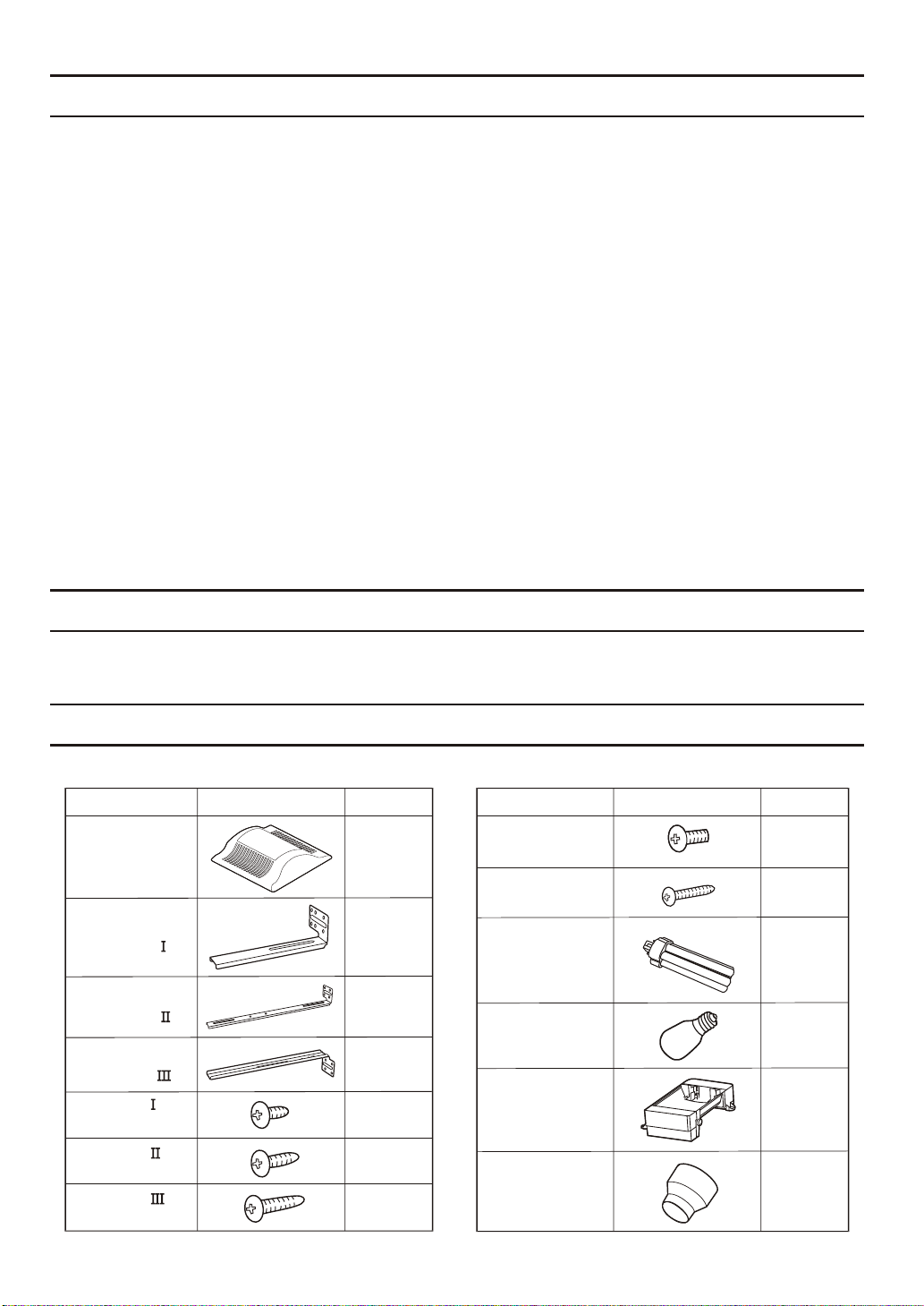
SUPPLIED ACCESSORIES
FV-05VFL3 FV-08VFL3 FV-11VFL3
Part name Part nameAppearance AppearanceQuantity Quantity
Machine screw
Grille
Suspension
bracket
Suspension
bracket
Suspension
bracket
Screw
(ST4.2X8)
Screw
(ST4.2X12)
Screw
(ST4.2X16)
1
1
1
1
2
2
2
(M4X8)
Long screw
(ST4.2X20)
32W
Fluorescent
lamp
4W
Night lamp
Lighting unit
3 inches adaptor
connector
(optional part)
2
6
1
1
1
1
4
Page 5
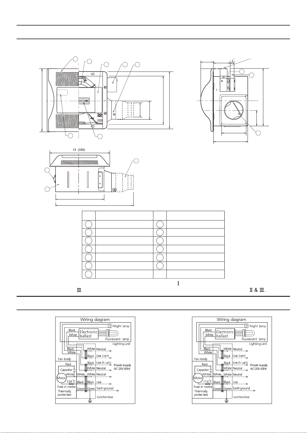
DIMENSIONS
FV‑05VFL3
FV‑08VFL3
FV‑11VFL3
13 (330)
9
8
1
2
7
10 1/4 (261)
6
16 1/8 (410)
No. Part name
1
Grille
Fan
2
Lighting unit
3
4
Junction box cover
Adaptor
5
Fluorescent lamp
6
Night lamp
7
2 7/8 (73)
3
4
5
10 1/4 (259)
11 7/8 (301)
3 7/8 (98)
2 15/16 (74)
10
3 1/ 2 (90)
1 (26)
No. Part name
Fan body
8
9
Bracket cover
Adaptor connector
10
11
Junction box
Suspension bracket
12
Damper
13
Unit: inches(mm)
1 (25)
11
12
4 3/8 (110)
5 1/ 2 (141)
1 3/4 (45)
3 1/4 (81)
13
13 1/4~15 1/2 (336~394)
16 1/2~18 3/4 (419~480)
21 1/4~23 1/2 (540~597)
(For 16 inches on center joists, only use suspension bracket , for 19.2 inches on center joists, only use
suspension bracket , lf more than 19.2 inches on center joists, use suspension bracket )
WIRING DIAGRAM
FV-05VFL3
FV-08VFL3
FV-11VFL3
5
Page 6
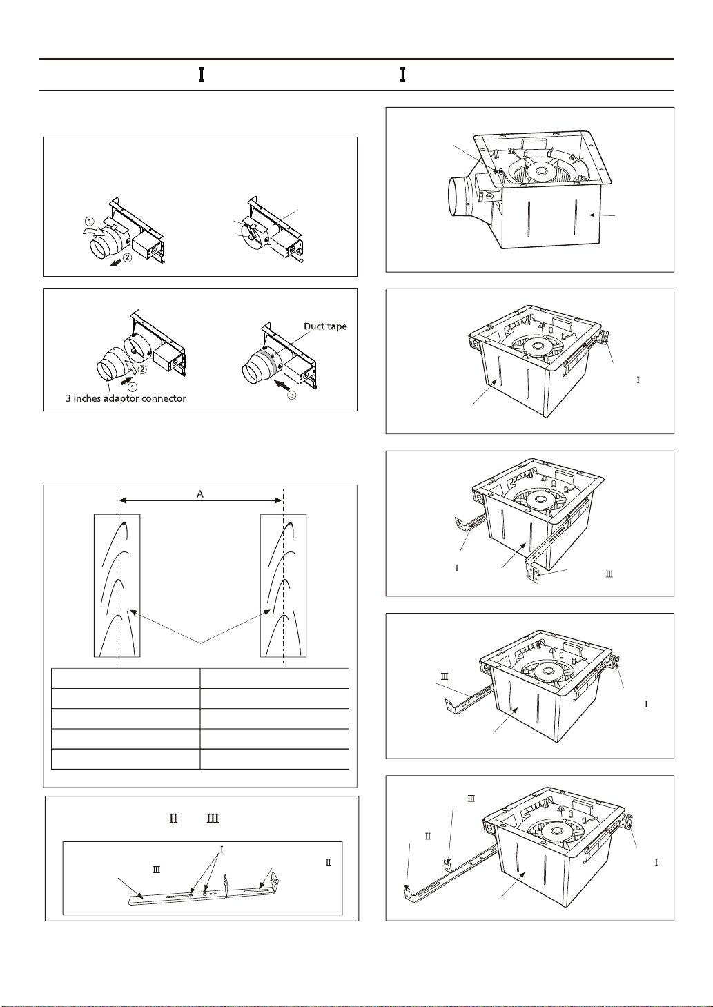
INSTALLATION (JOIST MOUNTING- )
1. Before installation, secure the fan body to adaptor
by using machine screw (M4X8). (Fig. 1)
IMPORTANT:
Remove the tape from damper and adaptor
before installation. As shown below:
Machine screw
(M4X8)
Tape
Adaptor
Damper
Connection method for 3 inches adaptor connector
2. lnsert the suspension bracket into the fan body
and adaptor. (Select the suspension bracket as
shown below)
Fan body
Suspension
bracket
Fan body
Suspension
bracket
Suspension
bracket
Fan body
Fig. 1
Fig. 2-1
Fig. 2-2
Joists
Spacing A on center joists
12 inches
16 inches
19.2 inches vertical joists
24 inches
lnsert Suspension bracket
Refer to Fig. 2-1
Refer to Fig. 2-2
Refer to Fig. 2-3
Refer to Fig. 2-4
lf spacing A on center joists is 24 inches, connect
suspension bracket and (C4 mark to C4 mark)
as shown below:
2 Screw (ST4.2X8)
Suspension bracket
Suspension bracket
6
Suspension
bracket
Suspension
bracket
Fan body
Suspension
bracket
Fan body
Suspension
bracket
Fig. 2-3
Suspension
bracket
Fig. 2-4
Page 7
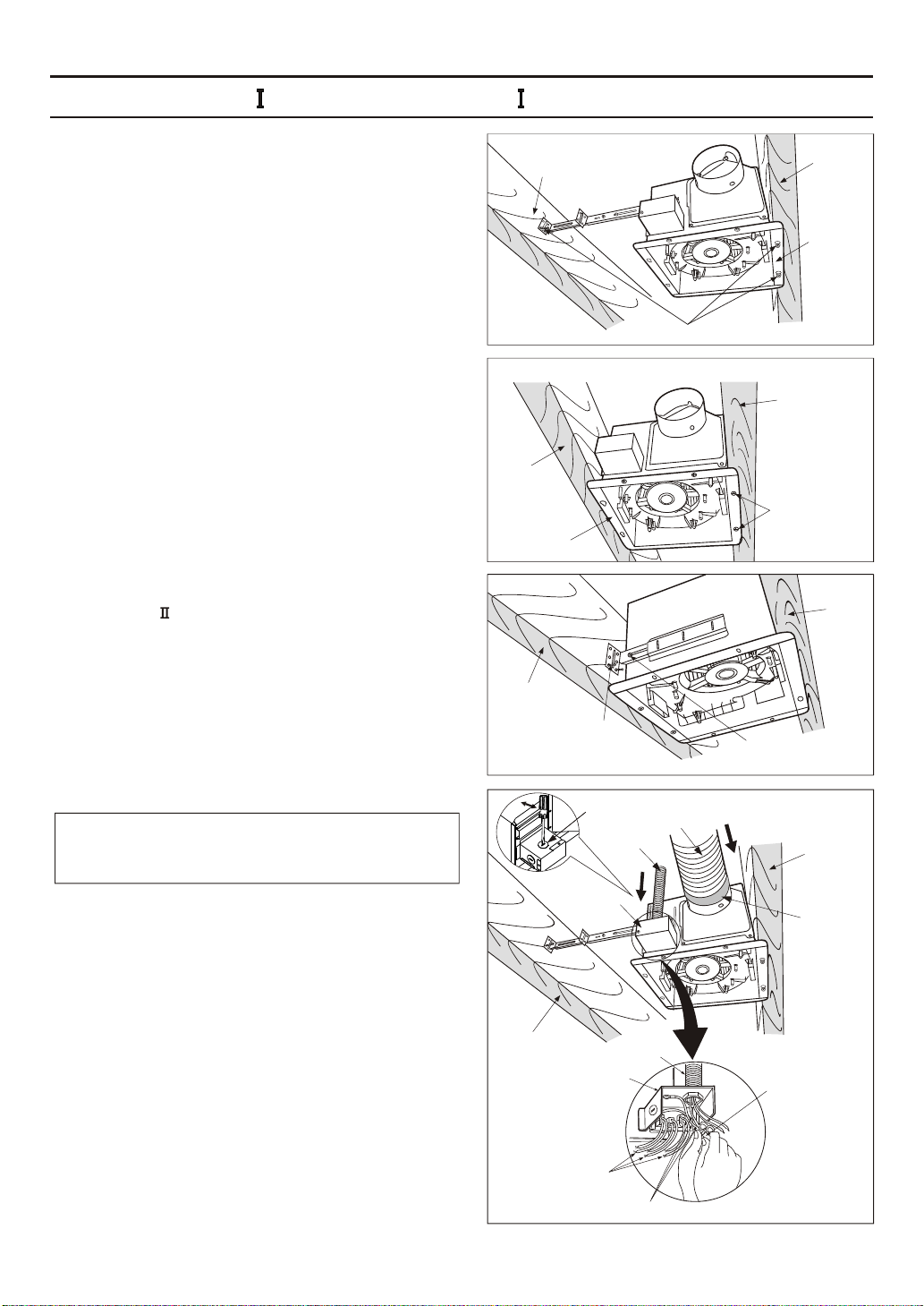
INSTALLATION (JOIST MOUNTING- ) CONTINUED
3. Install the suspension bracket and the flange of fan
body to joists by using long screws(ST4.2X20). (If
spacing A between joists is 10 1/4~12 inches, install
the flange of fan body according to Fig. 3-2, others
according to Fig. 3-1 install the product.)
4. Install the suspension bracket to joists by using long
screws (ST4.2X20) and secure it to the fan body by
using screw (ST4.2X12). (Fig.4)
5. Remove junction box cover and secure conduit or
stress relief to junction box knock-out hole. (Fig.5)
6. Refer to wiring diagram (page 5).
Using wire nuts, connect house power wires to
ventilating fan wires:
black to black; white to white; green to green;
Replace the junction box cover. (Fig.5)
CAUTION:
Mount junction box cover carefully so that lead
wires are not pinched.
7. lnstall a circular duct (using 4 inches duct or 3 inches
duct) and secure it with duct tape or clamps.
Joist
A=10 1/4~12 inches
Joist
Fan body
Joist
2 Long screws
(ST4.2X20)
Knock-out hole
Junction box
cover
4 Long screws (ST4.2X20)
Circular duct
Conduit
Joist
2 Long screws
(ST4.2X20)
Screw
(ST4.2X12)
Joist
Fan body
Fig. 3-1
Fig. 3-2
Joist
Fig. 4
Joist
Duct tape
or clamps
Joist
Conduit
Junction box
Lead wires
Green wires
Wire nut
Fig. 5
7
Page 8
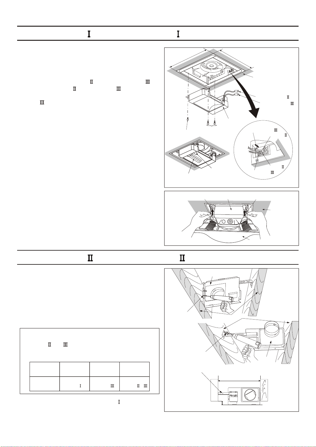
INSTALLATION (JOIST MOUNTING- ) CONTINUED
8. Finish ceiling work. Ceiling hole should be aligned
with the edge of the flange. (Fig.6)
10 7/ 2758 ( )
)10 7/8 (275
9. Insert the plug connector and plug connector
into the receptacle and receptacle respectively,
and secure the lighting unit to the fan unit with 2
screw (ST4.2X16) and 1 machine screw (M4X8).
(Fig.6)
10. Insert the fluorescent lamp and screw the night
lamp into the lighting unit. (Fig.6)
11. Insert mounting springs into slots as shown
and mount grille to fan body. (Fig.7)
Machine screw
(M4X8)
Fluorescent lamp
Unit: inches (mm)
Screw
(ST4.2X16)
4 W Night Lamp
Lighting unit
Slot
Lighting unit
Ceiling
Plug connector
Plug connector
Plug connector
Plug connector
Receptacle
Receptacle
Mounting spring
Grille
Fig. 6
Ceiling
Fig. 7
INSTALLATION (JOIST MOUNTING- )
1. Disconnect plug connector from receptacle and
remove adaptor from fan body before starting
installation.
2. Insert the suspension bracket into the adaptor and
secure it to joists by using long screws (ST4.2X20).
(Fig.8)
Ensure that distance B (7/8 inch, 21.6mm) for the
thickness of ceiling board.
If spacing A between joists is 21 1/4 to 23 1/ 2
inches, (540mm~597mm), connect suspension
bracket and (C4 mark to C4 mark) according
to page 6. Select the suspension bracket according
to spacing A as shown below.
Spacing A
between Joists
inches (mm)
suspension
bracket
13 1/4~15 1/ 2
(336~394)
suspension
bracket
16 1/ 2~18 3/ 4
(419~480)
suspension
bracket
21 1/ 4~23 1/ 2
(540~597)
suspension
bracket &
3. Follow step 5 to 7 of the installation (page 7) to
complete the duct work and wiring.
8
2 Long screws
(ST4.2X20)
Unit: inches (mm)
Adaptor
2 Long screws
(ST4.2X20)
Suspension bracket
Joists
13 1/4~15 1/ 2(336~394)
16 1/ 2~18 3/ 4(419~480)
21 1/ 4~23 1/ 2(540~597)
A
B
7/8 (21.6)
Adaptor
Fig. 8
Page 9
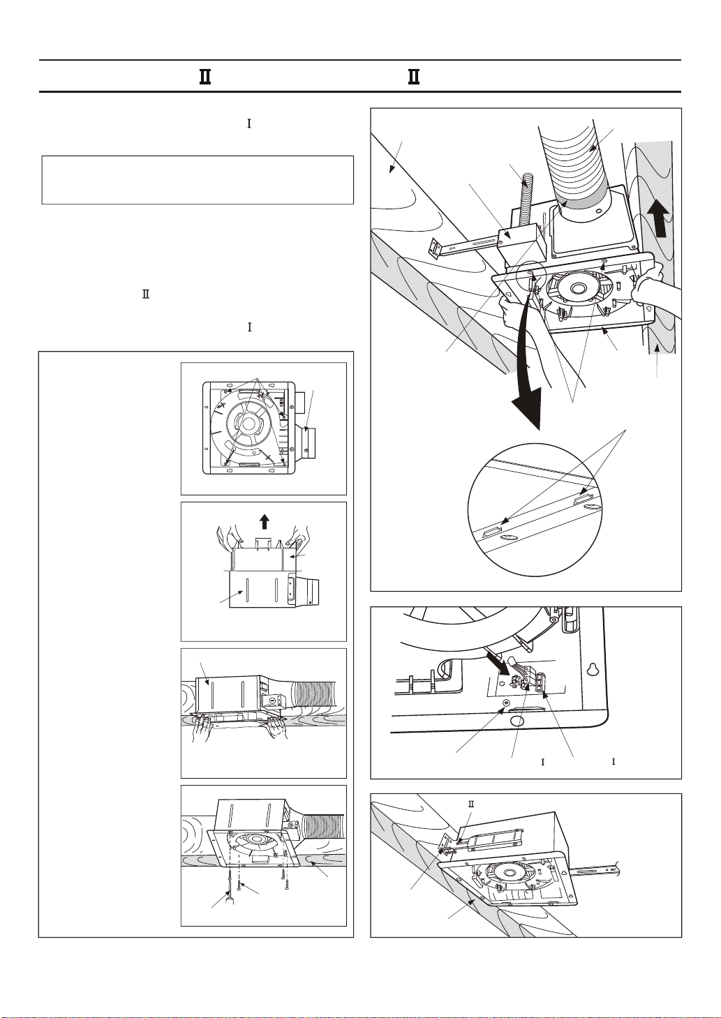
INSTALLATION (JOIST MOUNTING- ) CONTINUED
4. Insert the suspension bracket into fan body
(refering to step 2 of installation , page 6).
5. Insert the fan body into joists. (Fig.9)
IMPORTANT:
Make sure that adaptor claws are properly inserted
into body slots.
6. Secure the fan body to adaptor by using machine
screw (M4X8) and plug connector to receptacle.
(Fig.10)
7. Secure the suspension bracket to joists by using
long screws (ST4.2X20) and secure it to fan body
by using screw (ST4.2X12) in vertical direction.
(Fig.11)
8. Follow step 8 to 11 of installation (page 8) to
complete the installation work.
When mounting
body and blower
4 Screws
Adaptor
separately
1. Loosen 4 screws (but
do not remove them
from blower). (Fig.12-1)
2. Remove blower section.
(Fig.12-2)
Fig. 12-1
Joist
Junction box cover
Duct tape
or clamps
Conduit
Slots
Circular duct
Fan body
Adaptor
claws
Joist
3. Remove adaptor from
fan body and secure it
to joists as in Fig. 8 of
page 8.
4. Insert fan body
(without blower section)
into joists. (Fig. 9)
5. Secure the adaptor to
fan body by using
machine screw.
(M4X8). (Fig. 10)
6. Secure the fan body
to joists by using long
screws (ST4.2X20).
(Fig. 11)
7. Insert the blower into
the fan body. (Fig. 12-3)
8. Secure the blower.
(Fig. 12-4) and plug
connector to receptacle.
(Fig. 10)
Fan body
Fan body
Screw driver
4 Screws
Blower
Fig. 12-2
Fig. 12-3
Joist
Fig. 12-4
Machine
screw
(M4X8)
2 Long screws
(ST4.2X20)
Plug connector
Screw (ST4.2X12)
Joist
Receptacle
Fig. 9
Fig. 10
Fig. 11
9
Page 10
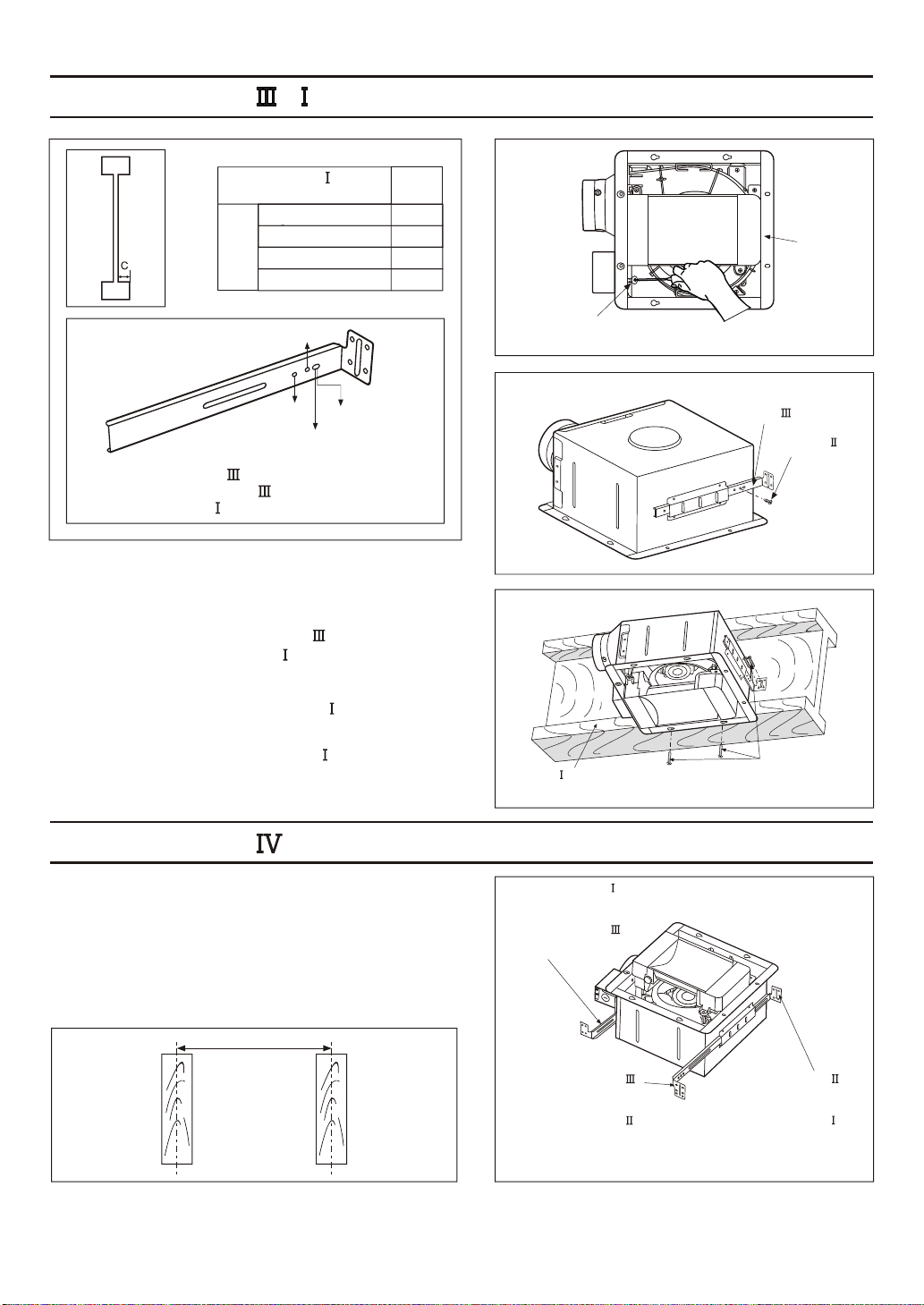
INSTALLATION ( - JOIST MOUNTING )
4 kinds of -joist
inches (mm)
9/16 (14.3)
11/16 (17.5)
C
31/32 (24.6)
1 17/32 (38.9)
hole
mark
C1
C2
C3
C4
C3
C4
C1
C2
Suspension bracket
The suspension bracket can comply with
different kinds of -joist.
1. Before installation, secure the fan body to adaptor by
using machine screw (M4X8) (Fig.13). Secure the
lighting unit to fan body (refering to Fig.6 of page 8).
2. Connect the suspension bracket to fan body. (Fig.14)
(Select the hole by checking -joist size fix the screw
to the frame hole.)
Machine screw
(M4X8)
Suspension
bracket
Fan body
Fig. 13
Screw
(ST4.2X12)
Fig. 14
3. Connect the ventilating fan to the -joist. (Fig.15)
4. Follow step 5 to 11 of installation (page 7~page 8) to
complete the installation work.
-Joist
INSTALLATION ( BETWEEN JOIST MOUNTING )
1. Before installation, secure the fan body to adaptor by
using machine screw (M4X8) (Fig.13). Secure the
lighting unit to fan body (refering to Fig.6 of page 8).
2. Insert the suspension bracket into bracket cover of
adaptor side and the back of the fan body. (Fig.16)
(select the suspension bracket according to spacing A
as shown below)
A
16 inches and 19.2 inches
horizontal joist
19.2 inches vertical joist
Suspension bracket
[16 inches and 19.2 inches
horizontal joist]
Suspension bracket
[19.2 inches vertical joist]
Suspension bracket
[16 inches and 19.2 inches
horizontal joist]
Suspension bracket
[19.2 inches vertical joist]
4 Long screws
(ST4.2X20)
Suspension bracket
[16 inches and 19.2 inches
horizontal joist]
Suspension bracket
[19.2 inches vertical joist]
Fig. 15
Fig. 16
10
Page 11
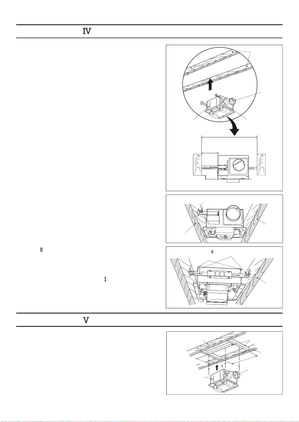
INSTALLATION (BETWEEN JOIST MOUNTING ) CONTINUED
3. Insert the fan body between joists.
Make sure the fan body is level and square
(perpendicular) with the joists. (Fig.17)
Ensure that distance B (7/8 inch, 21.6mm) for the
thickness of ceiling board.
4. Secure the suspension bracket to joists by using long
screws (ST4.2X20). (Fig.18, Fig.19)
Fan body
Unit: inches (mm)
2 Long screws (ST4.2X20)
13 1/4~15 1/ 2(336~400)
16 1/ 2~18 3/ 4(419~480)
3~5 (76~126)
5 4/ 5~7 4/5(148~198)
B
7/8 (21.6)
Joists
Adaptor
Junction box
A
Fig. 17
5. Secure the suspension bracket to fan body by using
screws (ST4.2X12). (Fig.19)
6. Follow step 5 to 11 of installation (page 7~ page 8)
to complete the installation work.
INSTALLATION (WOODEN HEADER )
1. Before installation, secure the fan body to adaptor by
using machine screw (M4X8) (Fig.13 of page 10).
Secure the lighting unit to fan body (refering to Fig.6
of page 8).
2. Install header between joists by using nails or screws.
3. Install the fan body and secure it by using longscrews
(ST4.2X20). (Fig.20, Fig.21 of page 12)
Joist
2 Screw
(ST4.2X12)
Joist
Fan body
Unit: inches (mm)
10 8
Joist
Fig. 18
4 Long screws
(ST4.2X20)
Joist
Fig. 19
Header
7/
)(275
14 3/4
Joist
(7)35
Adaptor
Fig. 20
11
Page 12
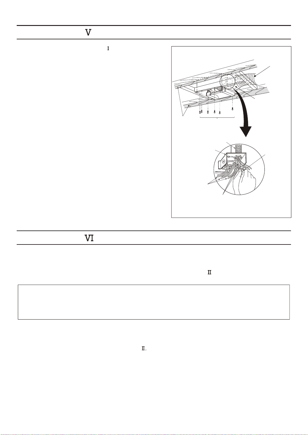
INSTALLATION (WOODEN HEADER ) CONTINUED
4. Follow step 5 to 11 of installation (page 7~page 8)
to complete the installation work.
Circular duct
Adaptor
Joists
Lead wires
6 Long screws
(ST4.2X20)
Conduit
Junction box
Green wires
Wire nut
Fig. 21
INSTALLATION (IN EXISTING CONSTRUCTION )
1. Installation in existing construction.
Installing the fan body in an existing building requires an accessible area (attic or crawl space) above
the planning installation location or existing ducting and wiring.
(1) To install the fan body, follow the procedures described in lnstallation . Take the following
precautions before installation.
CAUTION:
Check area above planning installation location to be sure that:
1. Duct work can be done and that area is sufficient for proper ventilation.
2. Wiring can be run to planning location.
3. No wiring or other obstructions shall interfere with installation.
(2) Inspect duct work and wiring before proceeding with installation.
(3) Plan suitable location for fan body. (next to ceiling joist)
(4) Before installation, provide inspection and maintenance access at a location that will not interfere
with installation work shown in installation
(5) First, remove ceiling section according to Fig.6 of page 8.
(6) Install fan body.
2. Installation from accessible area above fan location.
(1) Inspect duct work and wiring before proceeding with installation.
(2) Remove ceiling section according to Fig.6 of page 8.
(3) Install fan body.
12
Page 13
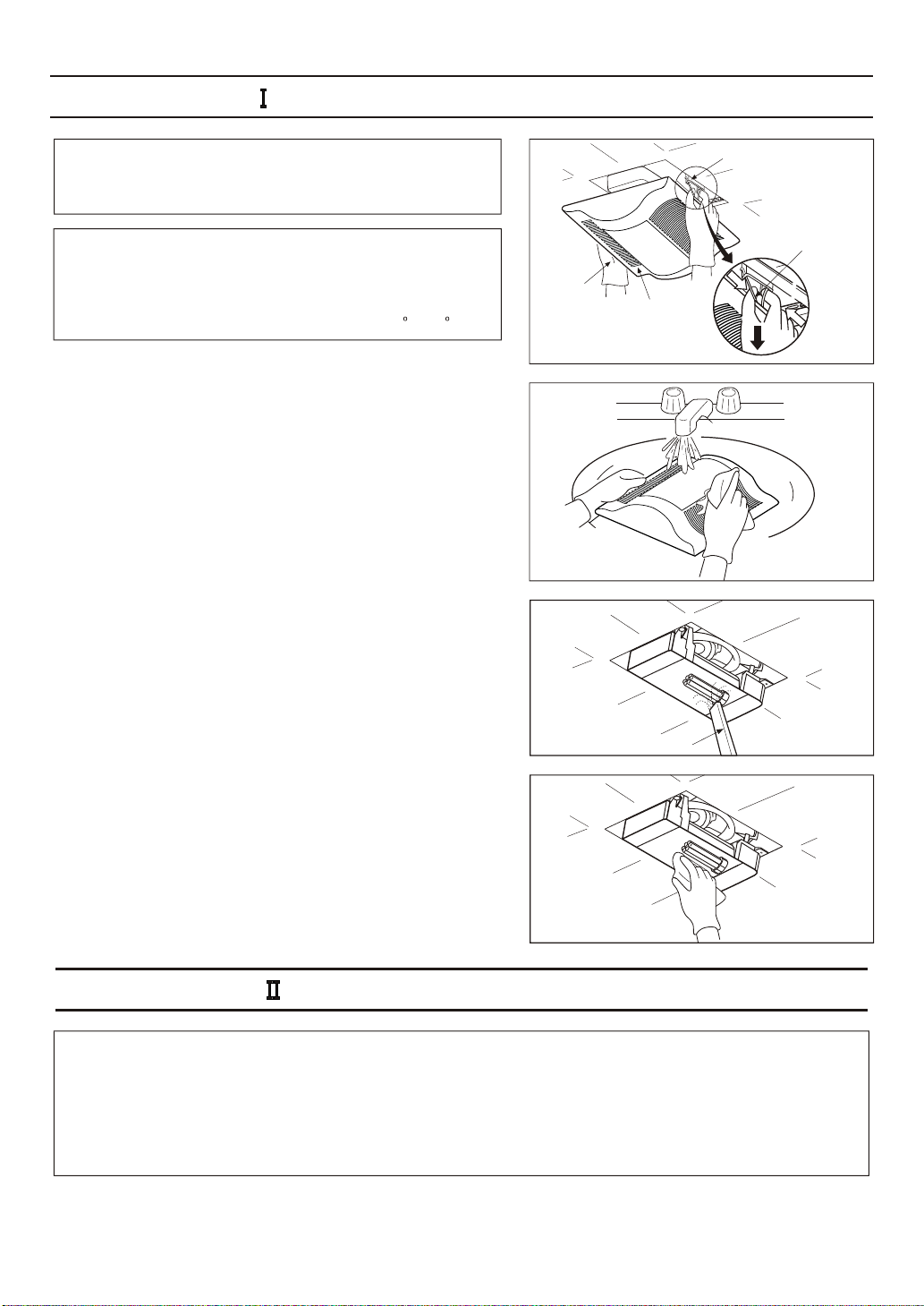
MAINTENANCE (CLEANING )
WARNING:
Disconnect power source before working on unit.
Routine maintenance must be done every year.
CAUTION:
1. Never use petrol, benzene, thinner or any other such
chemicals for cleaning the ventilating fan.
2. Do not damp water to enter motor.
3. Do not soak resin parts in water over 140 F(60 C).
1. Remove grille. (Squeeze mounting spring and pull down
carefully.) (Fig.22)
2. Wash and clean grille. (Use non-abrasive kitchen detergent,
wipe dry with new cloth.) (Fig.23)
3. Remove dust and dirt from fan body using a vacuum
cleaner. (Remove lamps if necessary.) (Fig.24)
Gloves
Grille
Slot
Mounting
spring
Fig. 22
Fig. 23
4. Using a cloth dampened with kitchen detergent, remove
any dirt from fan body. Wipe dry with new cloth. (Fig.25)
5. Replace lamps and grille.
Vacuum cleaner
MAINTENANCE (REPLACEMENT OF LAMP )
WARNING:
1. Disconnect power source before working on unit.
2. The lamp s glass is fragile. Please handle with care. To remove lamp, grasp at base and move back
and force to loosen. Do not pull hard on the lamp or you may break the glass.
3. 4W night lamp has threaded base. Remove by turning counterclockwise.
'
Fig. 24
Fig. 25
13
Page 14
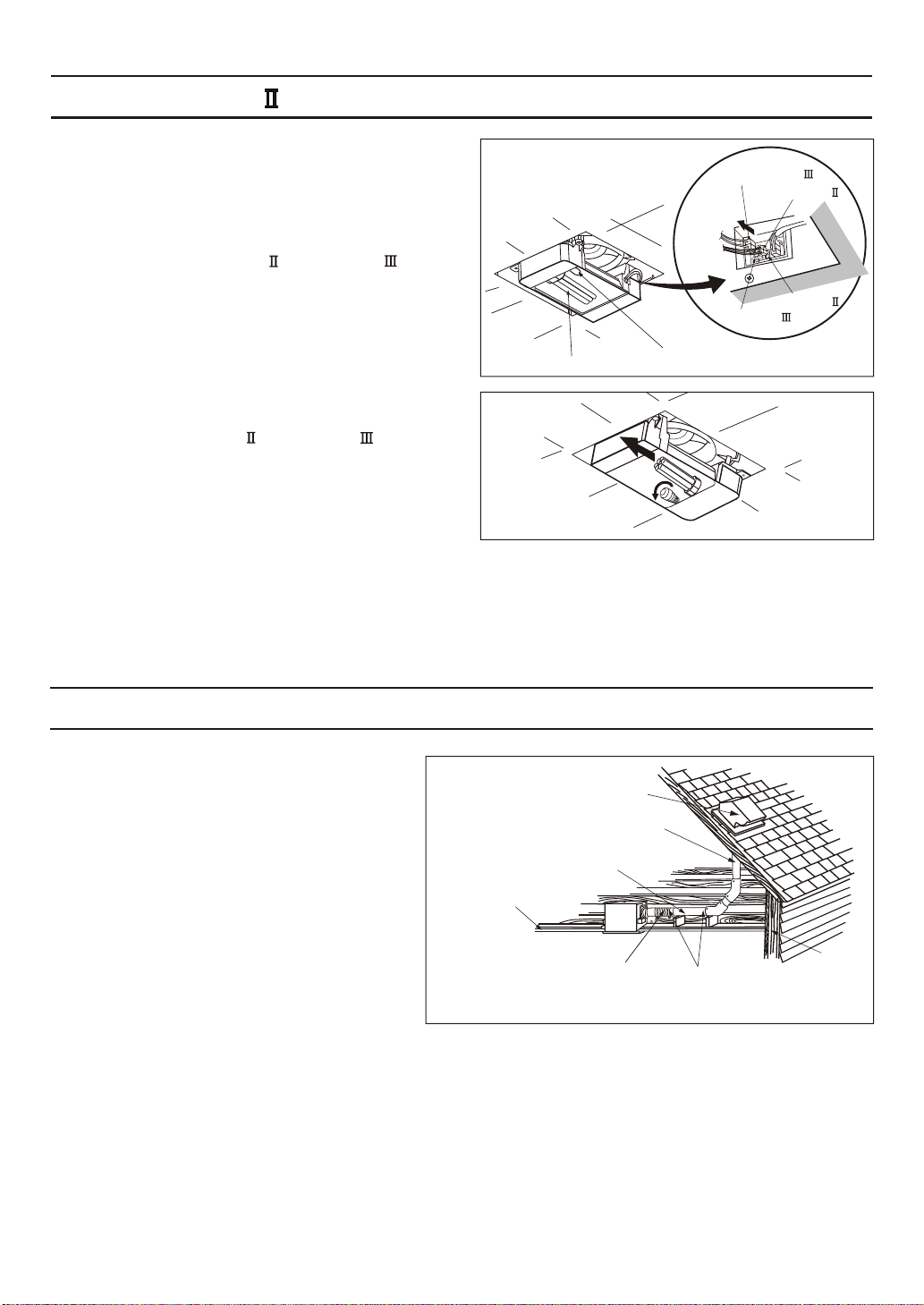
MAINTENANCE (REPLACEMENT OF LAMP ) CONTINUED
1. Remove grille. (Squeeze mounting spring and pull
down) (Fig.22 of page 13)
2. Disconnect the connector or connector of
lighting unit. (Fig.26)
Plug connector
Plug connector
Receptacle
Receptacle
3. Replace the fluorescent lamp (Panasonic
FHT32E35 32W) or the 4W night lamp,
connect the connector or connector and
replace the grille. (Fig.27)
PRACTICAL GUIDE TO INSTALLATION
Properly insulate the area around the fan
to minimize building heat loss and gain.
(Fig.28)
Loose fill or batt insulation can be placed
directly over the fan housing in the attic.
Our fans and fan/light combination units
do not create excessive heat that is a
common problem with recessed light
fixtures or some competitors fan/light
'
combinations. Our efficient, cool-running
motors and our fluorescent lamp do not
create enough ambient heat to be subjected
to these limitations.
4 inches or 6 inches roof jack, wall cap,
or soffit vent with backdraft damper
Mechanically connect duct to termination
and seal with mastic or approved foil
faced tape
2-3 ft straight run before elbow
In attic installation,
caulk box to drywall
Short piece of flexible duct helps
alignment and absorbs sound.
Clamps plus mastic or approved
foil faced tape at all flex joints
Fluorescent lamp
4 W Night Lamp
Foil tape tightly covers all metal
duct joints (glue PVC joints)
Fig. 26
Fig. 27
Insulation
Fig. 28
14
Page 15
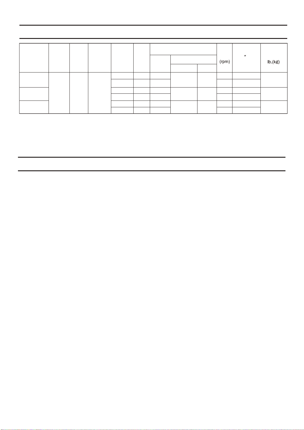
SPECIFICATIONS
Model
FV-05VFL3
FV-08VFL3
FV-11VFL3
Air
direction
Exhaust
Voltage
(V)
120 60
Frequency
(Hz)
Duct
diameter
(inches)
4
3
4
3
4
3
Noise
(sones)
<0.3
<0.3
0.5
0.6
1.3
1.5
Power consumption (W)
Fan body
16
15
30
30
33
33
Lighting unit
Fluorescent lamp
32
32
32
Night lamp
4
4
4
Air deliver at
Speed Weight
700
760
830
940
910
1050
0.1 WG
(cfm)
50
50
80
70
110
90
HVI Certified performance based on HVI Procedures 915, 916 and 920.
PRODUCT SERVICE
Warning Concerning Removal of Covers.
The unit should be serviced by qualified technicians only.
Your product is designed and manufactured to ensure a minimum of maintenance.
Should your unit require service or parts, call Panasonic Call Center at 1-866-292-7292 (USA)
or 1-800-669-5165 (Canada).
13.5 (6.1)
13.9 (6.3)
14.1 (6.4)
15
Page 16

Panasonic Corporation of North America
One Panasonic Way, Secaucus, New Jersey 07094
www.panasonic.com
Panasonic Canada lnc.
5770 Ambler Drive, Mississauga, Ontario L4W 2T3
www.panasonic.ca
Panasonic corporation 2012
Printed in China
T0212-0 08VFL3420
 Loading...