

Page 1
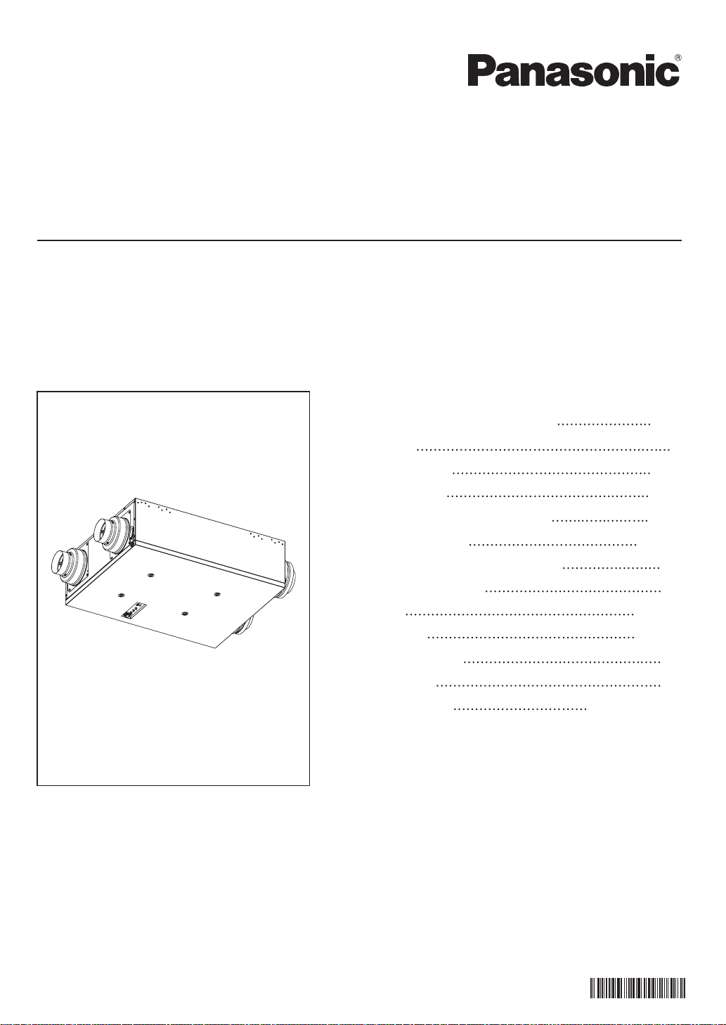
Installation and Operating Instructions
Energy Recovery Ventilator
Model No.
FV-10VEC2
FV-10VEC2H
FV-10VE2
FV-10VE2H
CONTENTS
GENERAL SAFETY INFORMATION
DESCRIPTION
WIRING DIAGRAM
WIRING METHOD
INSTALLATIONⅠ(WALL MOUNT)
DUCT INSTALLATION
INSTALLATIONⅠⅠ (CHAIN MOUNT)
START-UP PROCEDURE
OPERATION
MAINTENANCE
TROUBLESHOOTING
SPECIFICATIONS
PRODUCT SERVICE
2~3
4
4~5
5~6
7~8
8~11
12
13
13~15
16~17
18
19
BACK COVER
READ AND SAVE THESE INSTRUCTIONS
Thank you for purchasing this Panasonic product.
Please read these instructions carefully before attempting to install, operate or service the
Panasonic product. Please carefully read the “GENERAL SAFETY INFORMATION” (P.2~3) of
this manual before use. Failure to comply with instructions could result in personal injury or
property damage. Please explain to users how to operate and maintain the product after
installation, and this booklet should be presented to users.
Please retain this booklet for future reference.
10VC2M450B
Page 2
GENERAL SAFETY INFORMATION
For Your Safety
To reduce the risk of injury, loss of life, electric shock, fire, malfunction, and damage to
equipment or property, always observe the following safety precautions.
Explanation of symbol word panels
The following symbol word panels are used to classify and describe the level of hazard, injury,
and property damage caused when the denotation is disregarded and improper use is
performed.
Denotes a potential hazard that could result in death or
WARNING
serious injury.
CAUTION
NOTICE
The following symbols are used to classify and describe the type of instructions to be
observed.
This symbol is used to alert users to a specific operating procedure that must not be
performed.
This symbol is used to alert users to a specific operating procedure that must be
followed in order to operate the unit safely.
This symbol is used to alert users not to disassemble the equipment.
This symbol is used to alert users to make sure of grounding when using the
equipment with the grounding terminal.
Denotes a hazard that could result in minor injury.
Denotes a hazard that could result in property damage.
WARNING
When cutting or drilling into wall or ceiling, be careful not to damage electrical wiring
and other hidden utilities.
Solid state controls may cause harmonic distortion which can cause motor humming
noise. To reduce the risk of fire or electric shock, do not use this unit with any solidstate control device.
Canada only: Not to be installed in a ceiling thermally insulated to a value greater than
R40.
Never install the unit in a high humidity space, such as a bathroom, kitchen or laundry
room.
Do not install with a method which is not approved in the instructions.
Do not disassemble the unit. It may cause fire or electric shock.
Use this unit only in the manner intended by the manufacturer. If you have any
questions, contact the manufacturer.
Installation work and electrical wiring must be performed by qualified person(s) in
accordance with all applicable codes and standards, including fire-rated construction.
Ducted fans must always be vented to the outdoors.
2
Page 3
GENERAL SAFETY INFORMATION
Ceiling joist and wall stud must be subjected to static load more than five times the
weight of the product.
The special-purpose or dedicated parts, such as mounting fixtures, must be used if such
parts are provided.
Sufficient air is needed for proper combustion and exhausting of gases through the
flue (chimney) of fuel burning equipment to prevent backdrafting. Follow the heating
equipment manufacturer’s guideline and safety standards such as those published by
the National Fire Protection Association (NFPA), and the American Society for Heating
Refrigeration and Air Conditioning Engineers (ASHRAE) and the local code authorities.
Install the unit in the area where air temperature is above 50 °F (10 °C) to avoid
condensation in unit.
CAUTION
For general ventilating use only. Do not use to exhaust hazardous or explosive materials
and vapors.
Do not kink the power cord.
Do not install the unit in the area where the air stream temperature may exceed 104 °F
(40 °C).
The unit must be installed in a mechanical room, basement, or other conditioned space.
The OA duct and EA duct must be connected directly to the outside.
Make certain that the electric service supply voltage is AC 120 V, 60 Hz.
Follow all local electrical and safety codes, as well as the National Electrical Code (NEC)
and the Occupational Safety and Health Act (OSHA).
Always disconnect the power source before working on or near the fan, motor, fixture
or wiring cover.
Protect the power cord from sharp edges, oil, grease, hot surfaces, chemicals or other
objects.
These fans are intended for residential use only.
When the product is to no longer be used, it must not be left in place but removed,
to prevent it from possibly falling.
Disconnect power by switching off wall switch first, then main switch and unplug
before working on unit when replacing the jumper cable with wall switch.
NOTICE
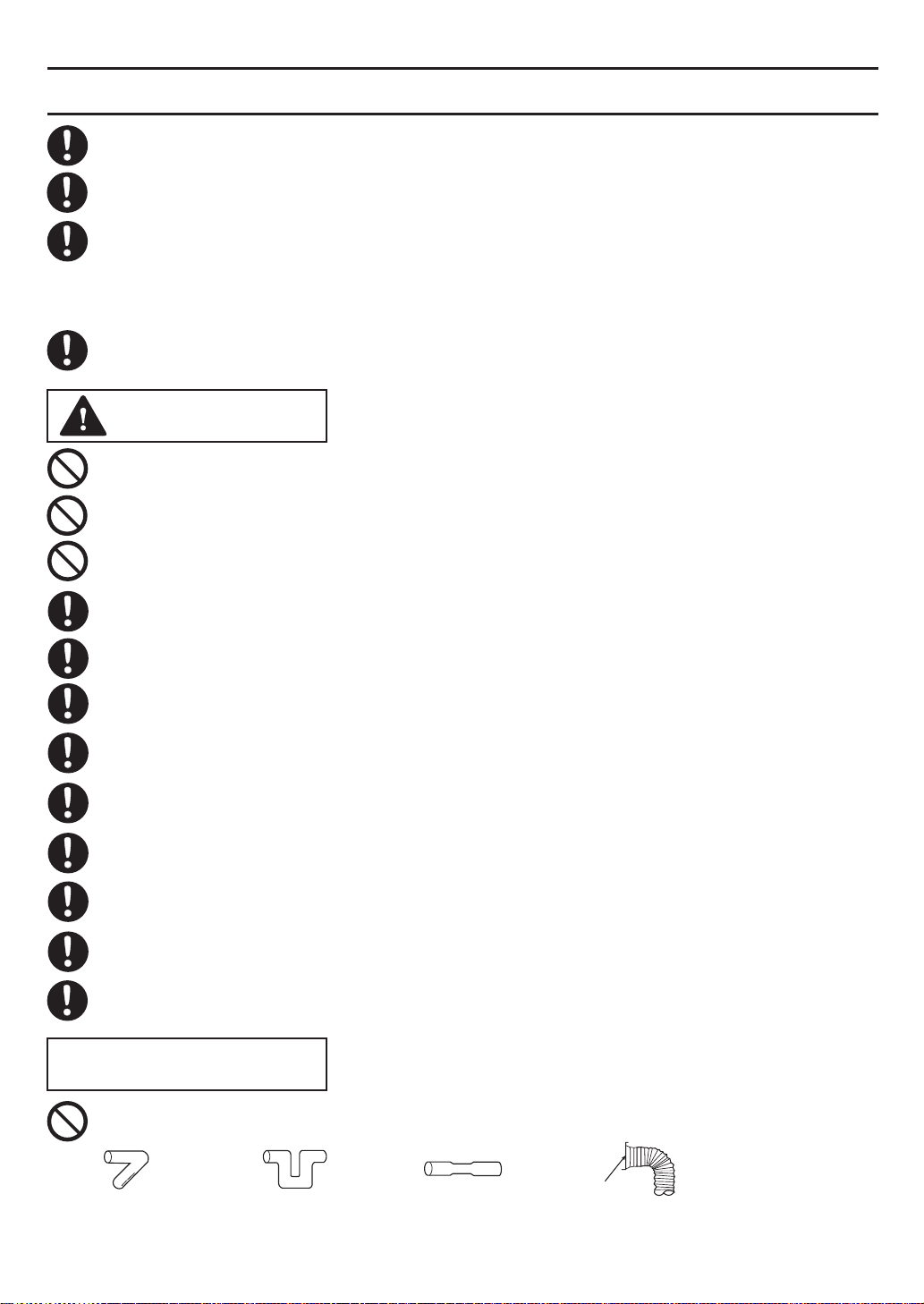
Do not install the unit where ducts are configured as shown below.
Adapter
Excessive bending Successive bending Squeezed duct Bend close to duct adapter
3
Page 4
DESCRIPTION
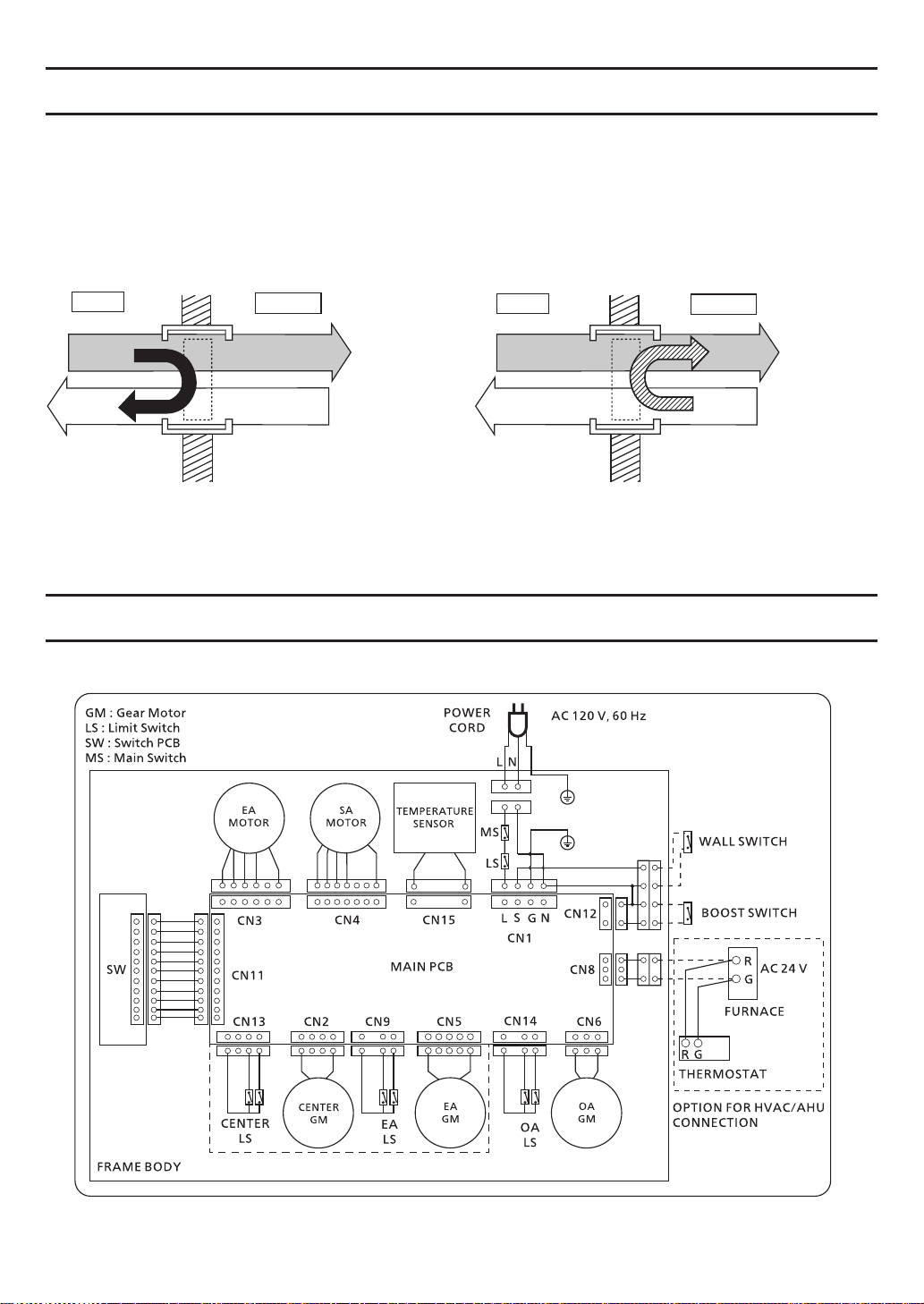
Energy Recovery Introduction: Compared to HRV (Heat Recovery Ventilator), ERV can also
transfer humidity and recover energy from that humidity. ERV can exchange energy
between “stale” EA and “fresh” OA, by transferring heat and moisture into the incoming cold
air, and pre-cooling and reducing the humidity of the incoming hot air. This helps maintain a
fresh environment even when the heating or cooling system is not operating.
Indoor
Stale air
Heat&
Moisture
Fresh air
Outdoor
<Heating>
WIRING DIAGRAM
FV-10VEC2/FV-10VE2
Exhaust air
(EA)
Outside air
(OA)
Indoor
Stale air
Fresh air
<Cooling>
Outdoor
Heat&
Moisture
Exhaust air
(EA)
Outside air
(OA)
OnlyFV-10VEC2
4
Page 5
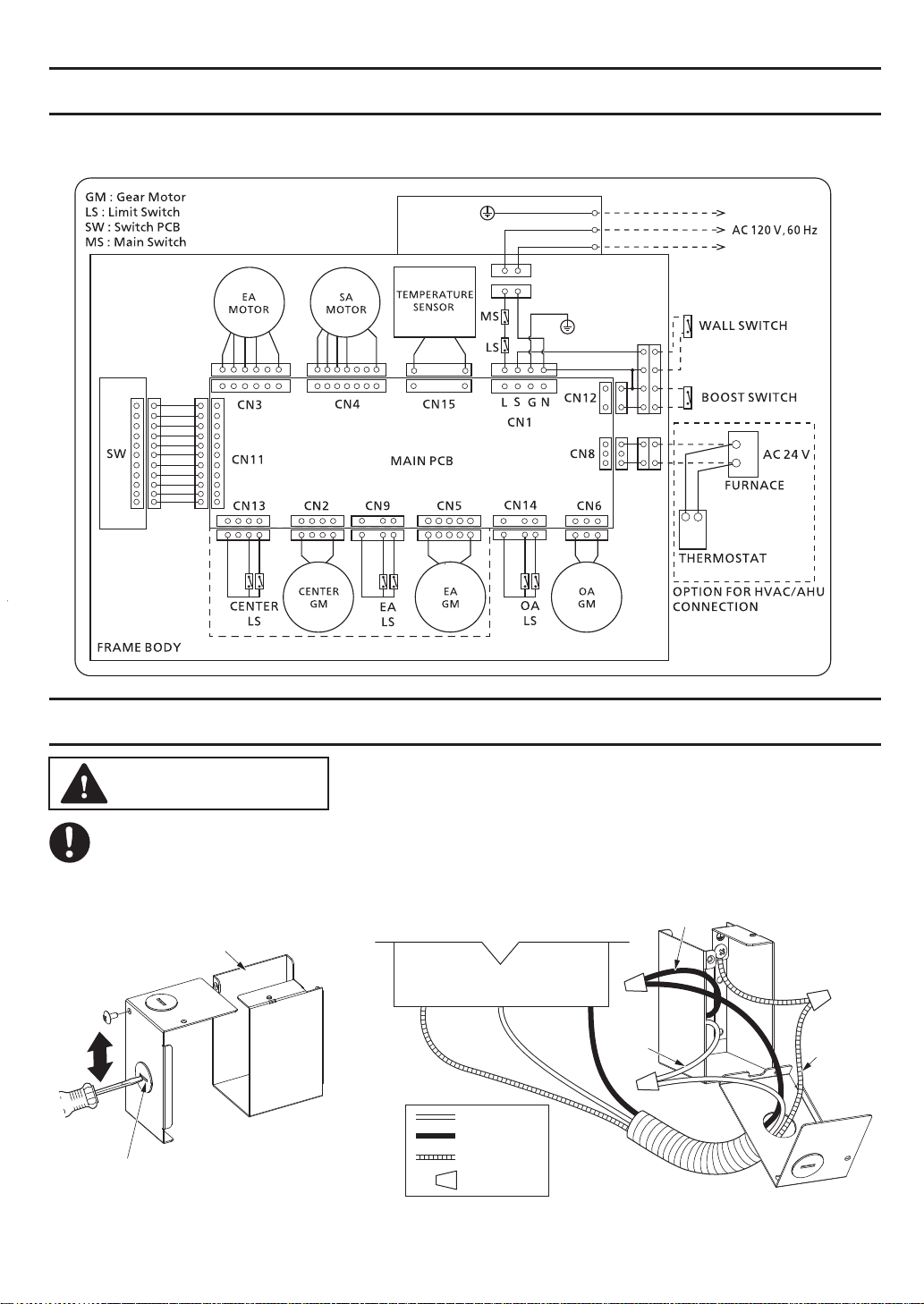
WIRING DIAGRAM
FV-10VEC2H/FV-10VE2H
OnlyFV-10VEC2H
JUNCTION BOX
GREEN
BLACK
WHITE
GROUND
LIVE
NEUTRAL
R
G
R G
WIRING
METHOD
WARNING
Installation work and electrical wiring must be performed by qualified person(s) in
accordance with all applicable codes and standards, including fire-rated construction.
For FV-10VEC2H, FV-10VE2H
Live
Junction box
Open knock out hole
AC 120 60Hz (Power supply)
Earth
ground
Neutral
WHITE
BLACK
GREEN
Wire Nuts
Live
Neutral
Earth
ground
5
Page 6
WIRING
METHOD
CAUTION
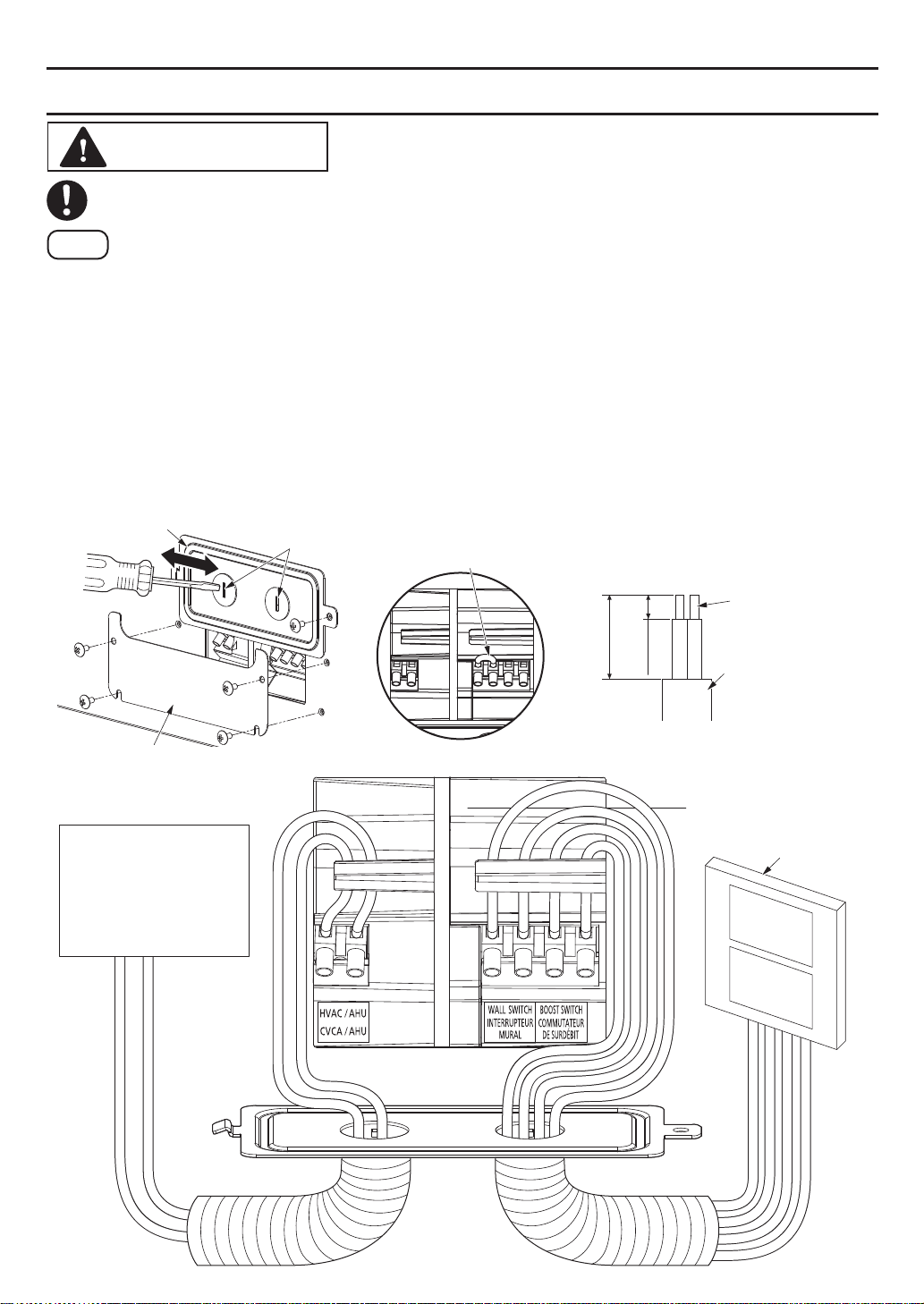
The capacity of wall switch, boost switch should be more than 120 V~3 A to control
the power of the product.
Note
(1)The terminal of wall switch has been connected by jumper cable as factory default.
If connecting with wall switch, please remove the jumper cable.
(2)The HVAC/AHU signal cord is optional, please connect it when you want to control
the HVAC/AHU.
If connecting with HVAC/AHU, the HVAC/AHU will turn on while ERV turns on.
(3)If you are not connecting to the HVAC/AHU, please open knock-out holes for wall
switch and boost switch connection only.
(4)Insert wires into the corresponding terminals deeply through the ribs.
Make sure the screw of terminal securely fastens the copper wire and the copper
wire is not exposed.
(5)Reinstall the wiring cover and maintenance plate.
Wiring cover
Maintenance plate
HVAC/AHU signal
Open knock out holes
Jumper cable
Unit: inches (mm)
4
~
100)
~
3 1/2
(90
1/4 (7)
Copper wire
Wall switch cord/
HVAC/AHU signal
cord/Boost switch
cord
Wall Switches
6
Page 7
INSTALLATIONⅠ(WALL MOUNT)
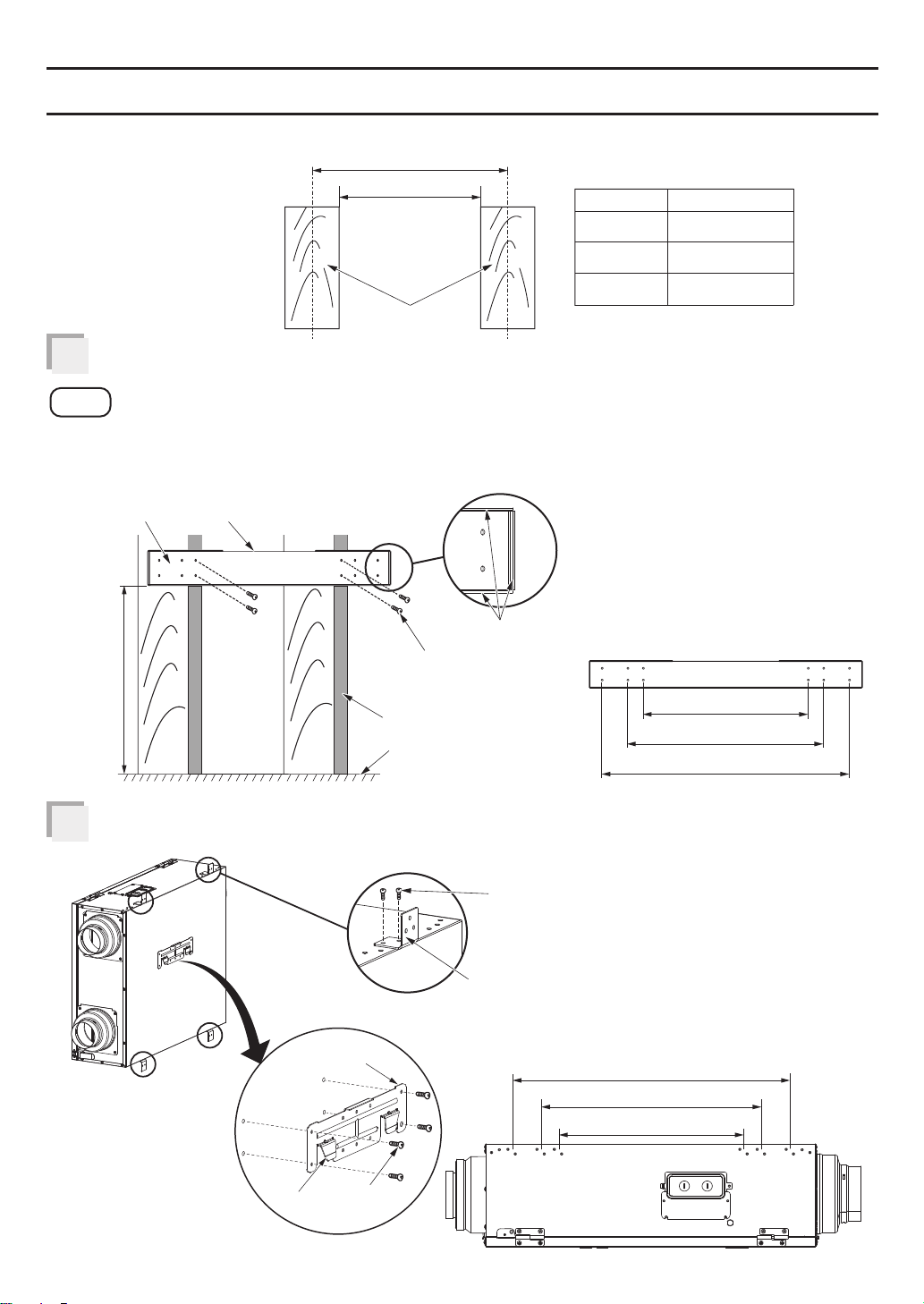
This method can be used in stud as below.
Unit: inches (mm)
A
B
16 (406.4)
19 (482.6) 17 1/2 (444.5)
A B
14 1/2 (368.3)
Mount wall bracket.
1
24 (609.6)
Stud
22 1/2 (571.5)
Note
(1)Attach with flanged edge facing outward and edge without flange facing upward
when mounting wall bracket.
(2)Choose the mounting hole on wall bracket according to the distance between studs.
Wall bracket
>31 1/2 (800)
Edge without flange
4-long screws
(ST4.2X30)
Stud
Floor
Flange
Unit: inches (mm)
16 (406.4)
19 (482.6)
24 (609.6)
Mount hangerⅠ and L plates.
2
Claw
Install L plates
Install HangerⅠ
HangerⅠ
4-screws
(M4X8)
2-screws
(M4X8)
L plate
24 (609.6)
19 (482.6)
16 (406.4)
7
Page 8
INSTALLATIONⅠ(WALL MOUNT)
Control panel comes to this side
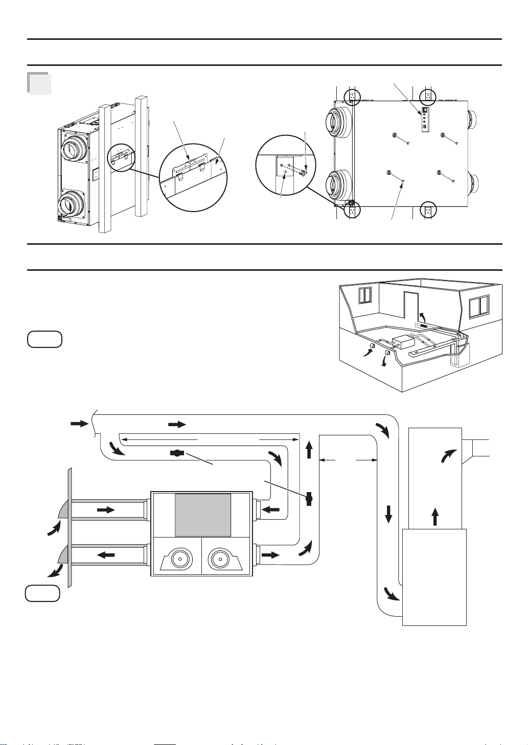
Hang ERV on to wall bracket.3
HangerⅠ
Wall bracket
2-long screws
(ST4.2x30)
Please use 3rd hole
in case it is not easy to
put screws due to Junction box.
DUCT INSTALLATION
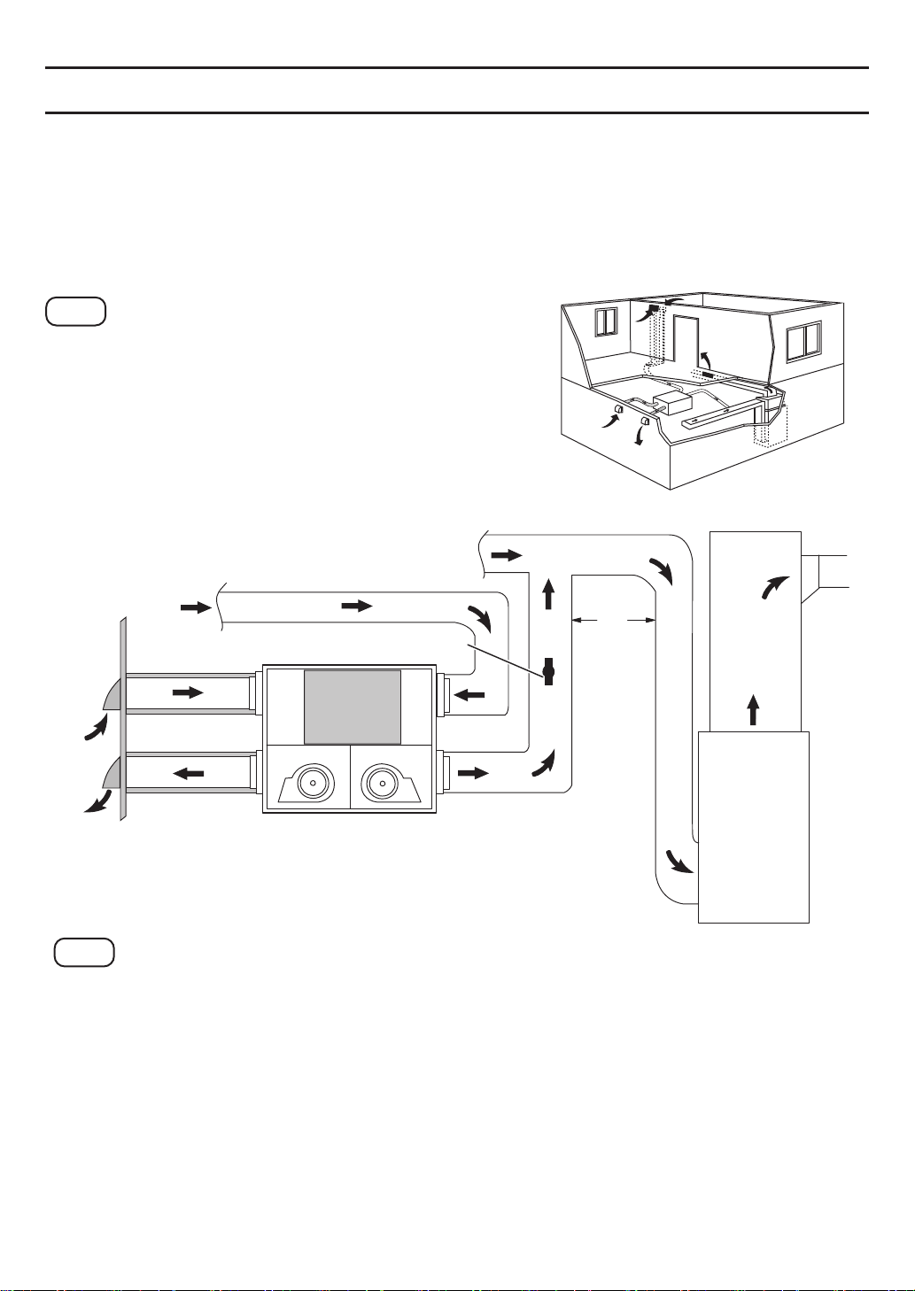
MethodⅠ- Simplified ducted installation (Return method)
This method draws return air from the return air duct
of the air furnace and supplies an equal amount of
outside air farther downstream into the return duct.
Note
(1)The ERV unit must be balanced.
It is mandatory that HVAC/AHU signal cord be connected.
(2)
(3)Check local codes and authority having
jurisdiction for acceptance.
4-plug covers
Return
air
Outdoors
40" (1 m) Min.
Dampers for
balancing
airflows
OA
EA
Return air
RA
SA
36”
(914 mm)
Min.
Air
furnace
Note
(1)Must Have 2-3 ft straight run on all duct attachments points
before elbow is more than 2 ft (610 mm).
(2)Unit is normally balanced on high speed with the furnace blower on.
(3)A minimum separation of 40 inches (1 m) is recommended between the two
direct connections.
(4)The exhaust air connection shall be upstream of the supply air connection to
prevent exhausting any fresh air.
(5)The distance between two outdoor hoods please see P.11.
(6)The airflow must be confirmed on site using the balancing procedures found in P.13.
8
Page 9
DUCT INSTALLATION
Method
ⅠⅠ
- Partially dedicated ducted installation
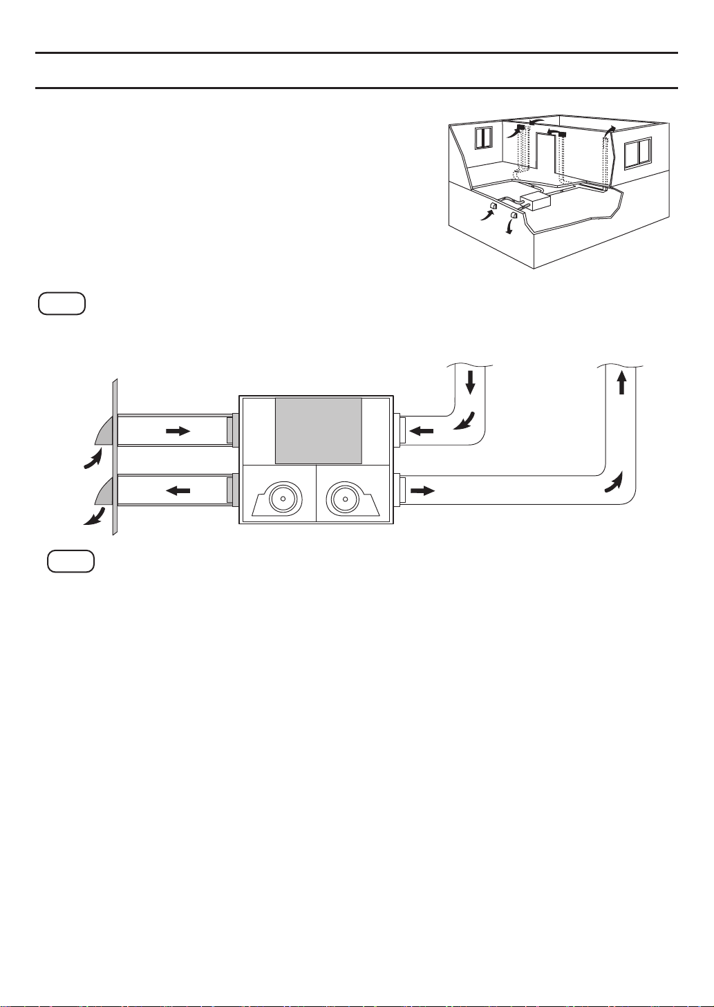
This method draws return air from specific points in the house and supplies an equal
amount of outside air into the return air duct of the air furnace.
Return air ducts of ERV should be installed in areas of the home where the poorest indoor
air quality exists (bathroom and kitchen).
The air furnace blower should be running when the ERV is operating to evenly distribute the
outside air throughout the house.
Note
(1)The ERV unit must be balanced.
(2)It is mandatory that HVAC/AHU signal cord be
connected.
(3)Check local codes and authority having
jurisdiction for acceptance.
Return air from various parts of home.
(i.e. bathrooms, kitchens, utility areas)
Outdoors
Return air
Dampers for
balancing airflows
Return air
36”
(914 mm)
Min.
OA
EA
RA
SA
Air
furnace
Note
(1)Must Have 2-3 ft straight run on all duct attachments points before elbow is more
than 2 ft (610 mm).
(2)Unit is normally balanced on high speed with the furnace blower on.
(3)The distance between two outdoor hoods please see P.11.
(4)The airflow must be confirmed on site using the balancing procedures found in P.13.
9
Page 10
DUCT INSTALLATION
Method
ⅠⅠⅠ
- Fully dedicated ducted installation
This method draws return air from specific points in the
house and supplies outside air to specific locations of
the house. This system is not connected to an air
furnace.
Return air ducts should be installed in areas of the
home where the poorest indoor air quality exists (bathroom and kitchen). Supply air ducts should be installed
to all bedrooms and living areas.
Note
(1)The ERV unit must be balanced.
(2)Check local codes and authority having jurisdiction for acceptance.
Outdoors
OA
Return air from various parts of home
(e.g. bathrooms, kitchens, utility areas)
RA
Supply air to main
living areas (e.g.
bedrooms, living
room)
EA
SA
Note
(1)Must Have 2-3 ft straight run on all duct attachments points before elbow
is more than 2 ft (610 mm).
(2)The distance between two outdoor hoods please see P.11.
(3)The airflow must be confirmed on site using the balancing procedures
found in P.13.
10
Page 11
DUCT INSTALLATION
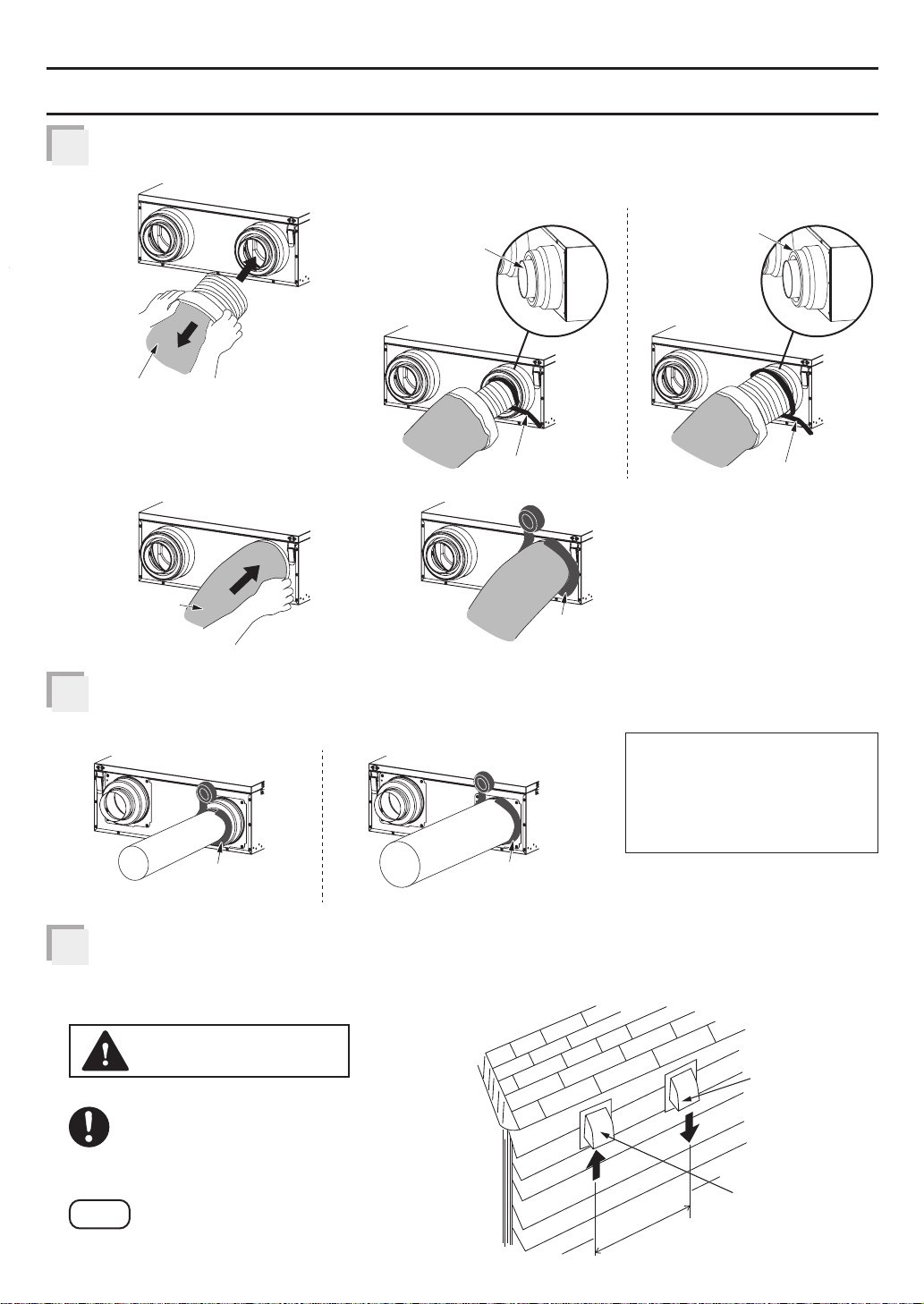
Install insulated ducts to the OA and EA adapter.
1
(1)
Pull back the insulation
(3)
Pull over the
insulation
Attach duct (rigid galvanized duct, etc.) to the SA and RA adapter.
2
OA
EA
(2)
Attach to 4” adapter
4” adapter
Tie wrap
(4)
Mastic or approved
foil tape
Attach to 6” adapter
or
6” adapter
Tie wrap
Attach to 4” adapter Attach to 6” adapteror
SA
Mastic or approved
foil tape
Install outdoor hood and connect with insulated ducts.
3
If separate hoods are used, locate them at least 10 ft (3 m) apart.
Seal hoods with caulk or other similar material.
RA
Mastic or approved
foil tape
CAUTION
The intake side duct must be
connected to the outside and at least
6 ft (1.8 m) away from the exhaust of
appliances such as furnace, dryer, fuel
burning appliances, etc.
Note
Please refer to the local codes for detail.
To avoid transmission of
vibrations, it is recommended
to use a 6-inch section of
flexible duct to connect
rigid ducts.
Exhaust hood
with backdraft
flap (s)
Intake hood
with bird screen
(No backdraft
10’ (3 m)
flap (s))
11
Page 12
INSTALLATIONⅠⅠ (CHAIN MOUNT)
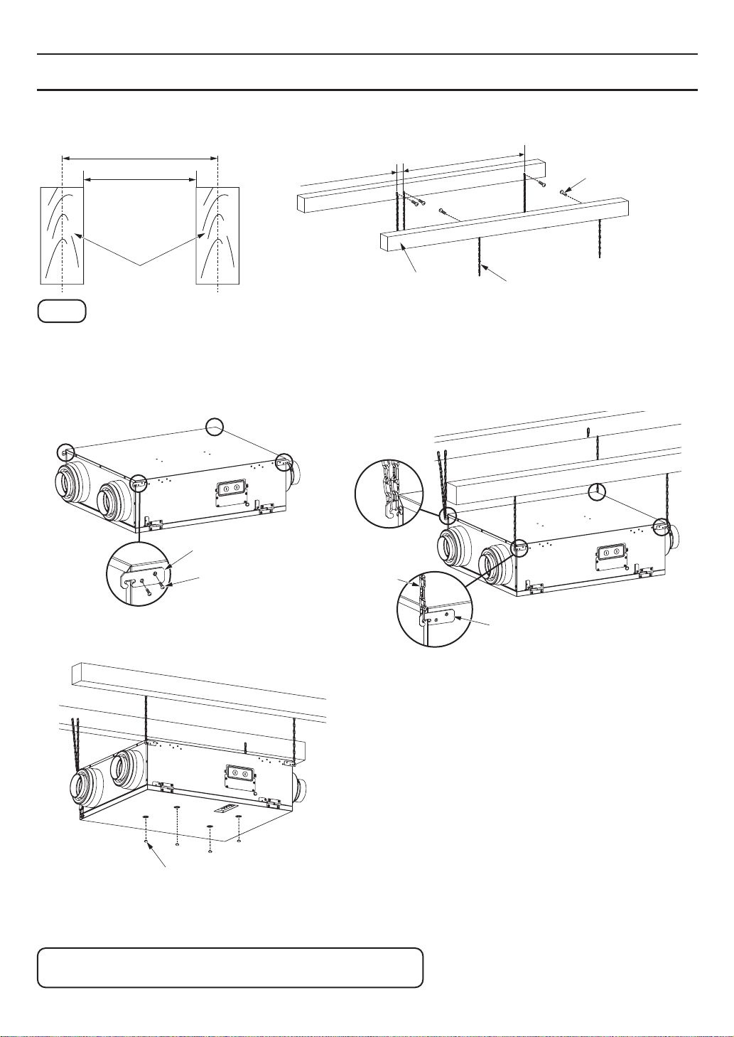
This method should be used in 24” joist as below.
Unit: inches (mm)
24 (609.6)
22 1/2 (571.5)
1 1/4 (31.8)
28 1/2 (723.6)
5-long
screws
(ST4.2X30)
Joist
Joist
5-chains
Note
(1)The chains are not supplied.
Please purchase chains which must be subjected to the weight of 66 lbs. (30 kg)
or above.
(2)Make sure ERV is horizontal after installation.
HangerⅠⅠ
2-screws
(M4X8)
Install HangerⅠⅠ
Chain
HangerⅠⅠ
Install chains to HangerⅠⅠ
4-plug covers
Duct installation please refer to P.8~P.11
12
Page 13
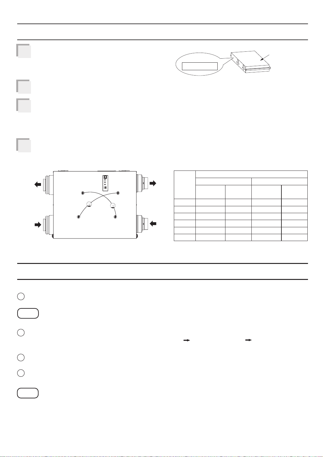
START-UP PROCEDURE
Fill in beginning time on the OA filter before
1
starting up the unit.
Connect the power then turn on the main switch on ERV.
2
If the ERV does not run, please check the wiring.
Check static pressure.
3
Using a manometer, measure the differential pressure of fresh air and exhaust air
respectively, then adjust the dampers for balancing airflows to make the test value
reach the differential pressure of setting volume as shown below.
Install the plug covers back when the check is complete.
4
Exhaust
air (EA)
Outside
air (OA)
Low Low
Fresh
High
Stale
High
Supply
air (SA)
Return
air (RA)
BEGINNING TIME:
The relation between volume
and differential pressure (reference)
Volume
(CFM)
The numbers in this table are the values after
installation.
FV-10VEC2
FV-10VEC2H
50
60
70
80
90
100
Differential pressure (Pa)
Fresh
FV-10VE2
FV-10VE2H
35 35
45 45
50 50
65 65
80 80
90 90
FV-10VEC2
FV-10VEC2H
OA filter
Stale
FV-10VE2
FV-10VE2H
55 70
75 90
95 115
120 145
155 195
175 225
OPERATION
<Control panel>
1
Main switch: Power on or off for ERV. Push the main switch
completely to the on/off position when turning on/off.
Note
The unit will consume some electricity unless you turn off the main switch.
2
ASHRAE time knob: The operation state will be changed with this knob. It is in units of
1 hour, for example: set to “10”, 10 minutes (ON) 50 minutes (OFF) 10 minutes (ON)...
cycle operation. The factory default is 60 Min/H.
3
SA knob: Set the supply air volume with this knob.
The factory default is 100 CFM.
4
EA knob: Set the exhaust air volume with this knob.
The factory default is 100 CFM.
Note
The SA air volume is limited less than “EA air volume + 20 CFM” when the outdoor
temperature is -22 °F (-30 °C)~14 °F (-10 °C). For example, when the EA air volume
setting is 50 CFM and the SA air volume setting is 100 CFM, actually the EA air volume
will be 50 CFM and the SA air volume will be 70 CFM.
13
Page 14
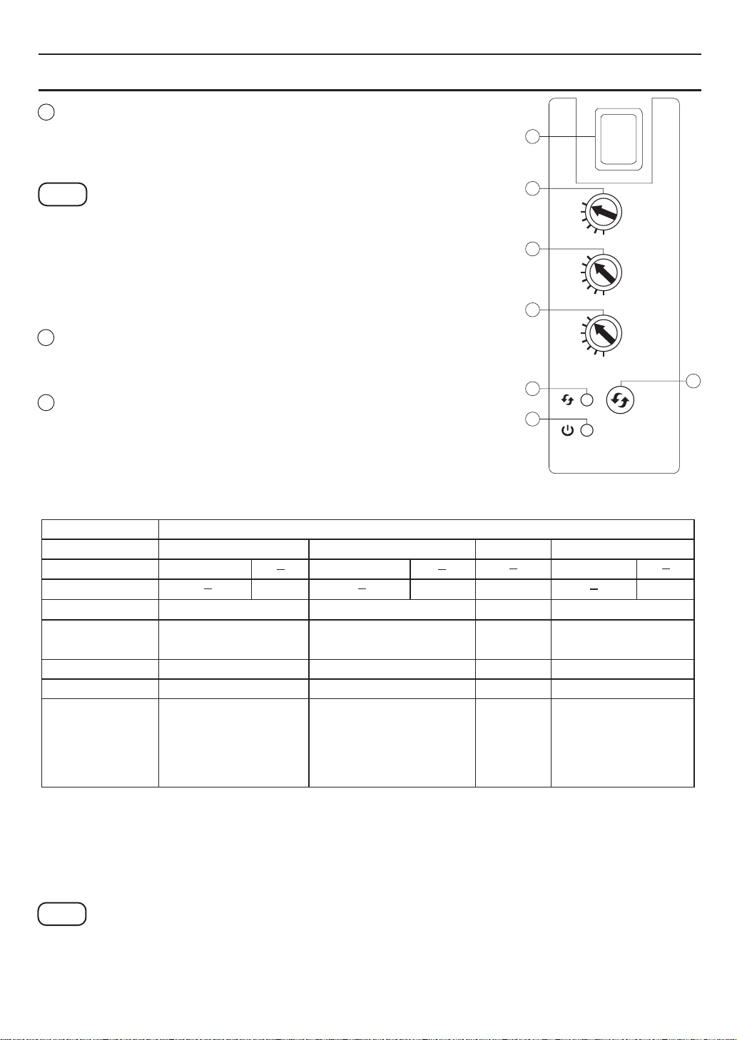
OPERATION
5
Filter indicator:
The indicator will be on when the product accumulated run
time reaches to 90 days. The buzzing will sound every hour
and 10 seconds in a hour.
Note
If you want to turn off the the indication of buzzer, please
press filter reset button about 3 seconds until there is the
sound of a long beep. Press filter reset button about 3
seconds again until there is sound of two quick beeps, the
buzzer indication will be turned on again.
6
Running indicator: When the indicator is on, indicates the
product is running.
Filter reset button: Press the button after filter maintenance
7
for resetting accumulatedrunning time.
30
20
60
50
60
50
I
O
min/h
min/h
10
Supply Air
(CFM)
Air fourni
(pi /min)
30
Exhaust Air
(CFM)
d'évacuation
30
(pi /min)
Bouton de
réinitialisation
du filtre
3
Air
3
Filter
Reset
Button
7
1
2
60
50
40
3
4
100
90
80
70
100
90
80
70
5
6
The ERV will run as below:
Setting
MAIN SWITCH
JUMPER CABLE
WALL SWITCH
BOOST SWITCH
ASHRAE TIME
SWITCH (min/h)
SA SWITCH (CFM)
EA SWITCH (CFM)
ERV ACTION
ON
CONNECTED
CONNECTED CONNECTED
ON
ON
10~60
30, 50~100 30, 50~100
30, 50~100 30, 50~100
ERV enforces the
following instructions
ASHRAE: 60 min/h
SA:100 CFM
EA:100 CFM
ERV restores setting
instructions of customer
ASHRAE: 10~60 min/h
SA:30, 50~100 CFM
EA:30, 50~100 CFM
State
ON ON OFF
ON
OFF ON/OFF
OFF
ON/OFF
10~60 10~60 10~60
30, 50~100
30, 50~100
Standby
30, 50~100
30, 50~100
Product is
power off.
ON/OFF
For example: when main switch and wall switch are ON, suppose the customer to set as
ASHRAE:50 min/h, SA:90 CFM, EA:90 CFM,
when boost switch is ON, ERV enforces the instructions ASHRAE:60 min/h, SA:100 CFM,
EA:100 CFM;
when boost switch is OFF, ERV restores setting instructions of customer ASHRAE:50 min/h,
SA:90 CFM, EA:90 CFM;
Note
It’s better that the product is operated for 24 hours in order to prevent from being frozen.
14
Page 15
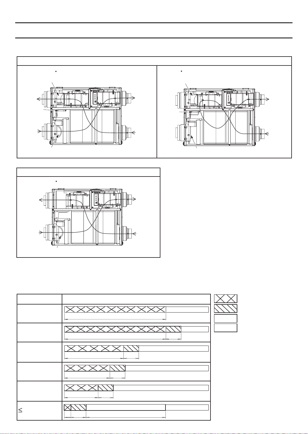
OPERATION
<Operation mode>
FV-10VEC2 and FV-10VEC2H are recommended for areas where temperature is -22 °F (-30 °C)~104 °F (40 °C).
FV-10VEC2,FV-10VEC2H
Circulation mode (for defrost)Heat exchange mode
EA damper open
Exhaust
air (EA)
Center
damper
closed
Outside
air (OA)
OA damper open
Supply
air (SA)
Center
damper
open
Return
air (RA)
FV-10VE2 and FV-10VE2H are recommended for areas where temperature is 14 °F (-10 °C)~104 °F (40 °C).
FV-10VE2,FV-10VE2H
Heat exchange mode
EA damper closed
Supply
air (SA)
Return
air (RA)
OA damper closed
Exhaust
air (EA)
Outside
air (OA)
OA damper open
Supply
air (SA)
Return
air (RA)
Example of FV-10VEC2 and FV-10VEC2H
When the ASHRAE timer is set to 60 min/h or the boost switch is on.
(The operation time of air exchange mode depends on the ASHRAE timer setting, and it is
automatically set to 60 min/h when the boost switch is on.)
Outdoor temp. Operation mode and time (min)
>14 °F (-10 °C)
14 °F (-10 °C)
5 °F (-15 °C)
5 °F (-15 °C)
-4 °F (-20 °C)
-4 °F (-20 °C)
-17 °F (-27 °C)
60
~
~
~
35
27
60 9
···
9
···
9
···
···
···
Heat exchange mode
Circulation mode
Stop operating
Repetition
-17 °F (-27 °C)
-22 °F (-30 °C)
-22 °F (-30 °C)
~
20
···
9
···
474 9
15
Page 16
MAINTENANCE
CAUTION
Electric shock may result. Disconnect power by switching off main switch first, then
unplug before working on unit when it is in default mode.
Electric shock may result. Disconnect power by switching off wall switch first, then
main switch and unplug before working on unit when replacing the jumper cable with
wall switch.
Routine maintenance must be performed every 2 or 3 months, clogged filters may
cause condensation on the unit due to air flow reduction.
Please wear gloves to avoid pinching fingers during maintenance.
Please pay attention to dust, condensation water or parts that may drop down when
the frame cover is opened.
Never use petrol, benzene, thinner or any other such chemicals to clean the ERV.
Do not allow water to enter ERV.
Do not immerse resin parts in water over 60 °C.
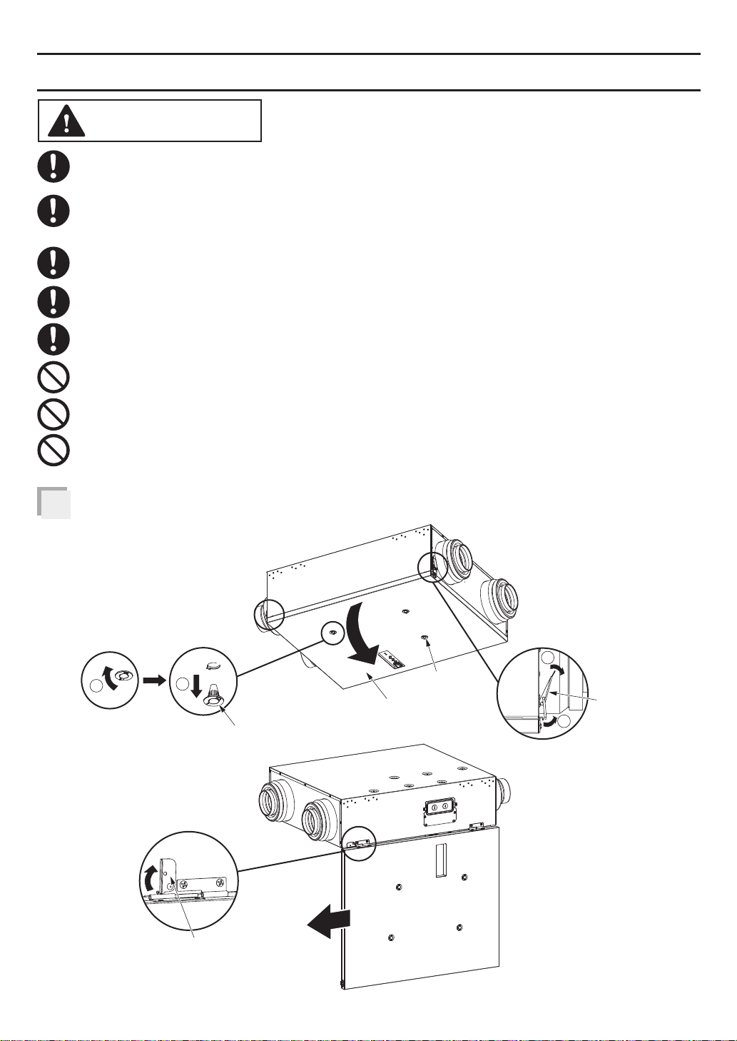
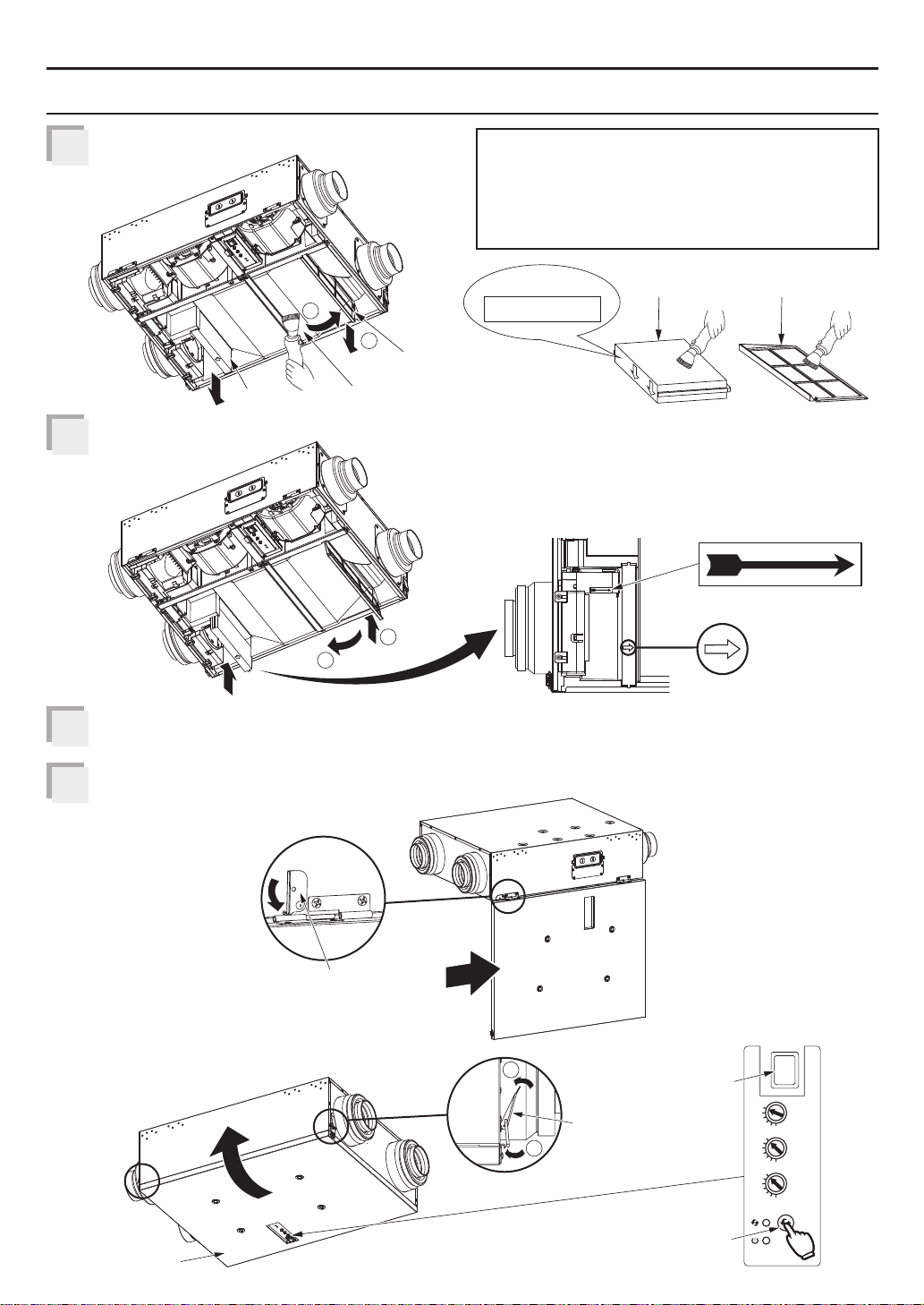
Open the frame cover by unlocking the latches.
1
After running in low
temperature, remove
4-plugs to discharge
condensed water.
1
You can detach the
frame cover by
releasing the lock
plate.
2
Plug
4-plugs
Frame cover
1
Latch
2
16
Lock plate
Page 17
MAINTENANCE
Clean the OA filter, RA filter and energy
2
recovery core.
1
2
Energy recovery core
2
Reinstall the filters.
3
OA filter
RA filter
1
It is suggested to replace the OA filter
every 6 months. Please fill in beginning
time on new OA filter before replacing.
Please replace OA filter by Panasonic
Model FV-FL0810VE1 or FV-FL1310VE1.
BEGINNING TIME:
OA filter
Make sure the direction of the arrow
on the OA filter is correct.
AIR FLOW
AIR FLOW
RA filter
AIR FLOW
AIR FLOW
Reinstall and close frame cover by locking the latches, then reset the lock plate.
4
Connect power, press filter reset button with sound of beep, then filter indicator and
5
buzzer sound will be off.
Lock plate
I
O
60
50
40
30
20
10
100
90
80
70
60
50
30
100
90
80
70
d'évacuation
60
50
30
réinitialisation
Frame cover
2
Main
switch
Latch
1
Filter reset
button
min/h
min/h
Supply Air
(CFM)
Air fourni
3
(pi /min)
Exhaust Air
(CFM)
Air
3
(pi /min)
Filter
Reset
Button
Bouton de
du filtre
17
Page 18
TROUBLESHOOTING
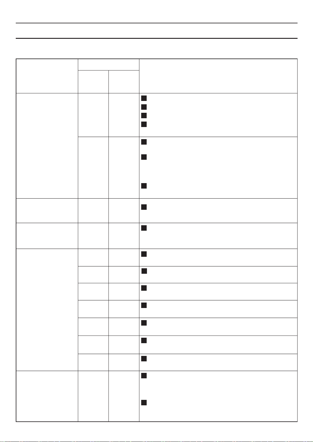
If a problem is encountered, please investigate it by going through the following items.
If the problem still persists, please disconnect the power and contact the dealer for repair.
Display
Problem
Running
indicator
(Green)
Off Off
Filter
indicator
(Red)
Action
Check the power is connected.
Check the frame cover is closed.
Check the main switch in product body is on.
Check if the spring on the inside of frame cover
is damaged or deformed.
1.The ERV doesn’t
work.
2.The HVAC/AHU
doesn’t work
when ERV works.
3.Buzzer sound
(10 sec in a hour)
and ERV works.
4.Buzzer sound
(30 sec in a hour)
and ERV doesn’t
work.
On Off
On Off
On
Blink*
(0.5 s)
Blink*
(2 s)
Off
Off
Off
Blink*
(0.5 s)
On
Off
Off
Blink*
(2 s)
Blink*
(4 s)
ERV running interval according to the ASHRAE
time setting.
When outdoor temperature is low (FV-10VEC2 and
FV-10VEC2H: ≤-22 °F (-30 °C), FV-10VE2 and
FV-10VE2H: ≤14 °F (-10 °C)), ERV stops operating
automatically.
Damper may be frozen shut, please wait for
maximum 24 hours for defrosting.
Please disconnect the power and contact the
dealer to check the HVAC/AHU wiring connect.
The RA filter and OA filter need to be maintained.
If you do not want the buzzer notification, please
long press the filter reset button for 3 sec to cancel it.
SA motor error, please disconnect the power
and contact the dealer for repair.
EA motor error, please disconnect the power
and contact the dealer for repair.
OA damper error, please disconnect the power
and contact the dealer for repair.
EA damper error, please disconnect the power
and contact the dealer for repair.
Center damper error, please disconnect the
power and contact the dealer for repair.
5.ERV doesn’t work
base on the setting
air volume.
18
The time under “Blink” means the frequency of blink.
*
Blink*
(0.5 s)
On
On
On
Blink*
(0.5 s)
Off
Temperature sensor error, please disconnect the
power and contact the dealer for repair.
PCB board error, please disconnect the power
and contact the dealer for repair.
When product runs in circulation mode for
defrosting, the air volume will be more than
setting and sound will be slightly louder than
normal operation. (FV-10VEC2 and FV-10VEC2H)
When outdoor temperature is less than 14 °F
(-10 °C), the product will restrict air volume
automatically to protect energy recovery core.
Page 19
SPECIFICATIONS
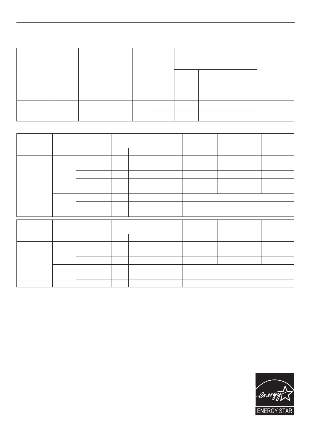
<Ventilation Performance>
Net air flow
(CFM)
Exhaust
100
100
100
100
Supply
Model No.
FV-10VEC2
FV-10VEC2H
FV-10VE2
FV-10VE2H
Air
direction
Exhaust
&
Supply
Exhaust
&
Supply
Voltage
(V)
120
120
Frequency
(Hz)
60
60
Duct
4“/6”
4“/6”
Static
pressure
0.1”WG
0.4”WG
0.1”WG
0.4”WG
<Energy Performance>
Model No. Mode
Heating
FV-10VEC2
FV-10VEC2H
Cooling
Supply
temperature
°F °C L/s CFM
32
95 35
0
-25
-25 30 64-13
Net air flow
252753
31 6632 0
40
Power
consumption
(W)
57-13
4923
29
39
68
77
100
32
663195 35 42
Model No. Mode
Heating
FV-10VE2
FV-10VE2H
Cooling
Supply
temperature
°F °C L/s CFM
95 35
Net air flow
0
25 5332
31 6632 0
40
Power
consumption
(W)
4923
29
39
68
32
663195 35 42
The testing of the ventilation performance and the energy performance is in accordance with CSA-C439 standard.
Sensible
recovery
efficiency
80%
77%
73%
65%
56%
Sensible
recovery
efficiency
80%
77%
73%
Power
consumption
(W)
Fan unit
100 81
90100
100 81
90100
Adjusted sensible
recovery efficiency
83%
81%
77%
67%
60%
Total recovery efficiency
60%
55%
Adjusted sensible
recovery efficiency
83%
81%
77%
Total recovery efficiency
60%
55%
Weight
Ib.()
50
(22.4)
48
(21.6)
Net
moisture
transfer
0.78
0.74
0.718532 0
0.71
0.58
Net
moisture
transfer
0.78
0.74
0.718532 0
For FV-10VEC2 and FV-10VEC2H
To ensure quiet operation of the ENERGY STAR certified H/ERV, each product model must be installed
using sound attenuation techniques appropriate for the installation.
The way your heat/energy-recovery ventilator is installed can make a significant difference to the
electrical energy you use. To minimize the electricity use of the heat/energy-recovery ventilator,
a stand-alone fully ducted installation is recommended. If you choose a simplified installation that
operates your furnace air handler for room-to-room ventilation, an electrically efficient furnace that has
an electronically commutated (EC) variable speed blower motor will minimize your electrical energy
consumption and operating cost.
Installation of a user-accessible control with your product model will improve comfort and may
significantly reduce the product model’s energy use.
This product earned the ENERGY STAR® by meeting strict energy efficiency guidelines
set by NaturalResources Canada and the US EPA. This product meets ENERGY STAR
requirements only when used in Canada.
19
Page 20
PRODUCT SERVICE
Warning Concerning Removal of Covers.
The unit should be serviced by qualified technicians only.
Your product is designed and manufactured to ensure a minimum of maintenance.
Should your unit require service or parts, call Panasonic Call Center at 1-866-292-7299 (USA)
or 1-800-669-5165 (Canada).
Two Riverfront Plaza, Newark, NJ 07102
www.panasonic.com
5770 Ambler Drive, Mississauga, Ontario L4W 2T3
www.panasonic.com
Panasonic Corporation 2023-2024
Printed in Mexico
Issue date:01/2024
P0523-2014 10VC2M450B-EN
 Loading...