

Page 1
INSTALLATION INSTRUCTIONS
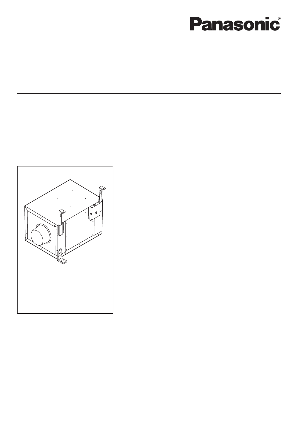
In-Line Fan
Model No.
FV-10NLF1E
FV-20NLF1
FV-30NLF1
FV-40NLF1
FV-10NLF1E FV-20NLF1 FV-30NLF1 FV-40NLF1
Contents
GENERAL SAFETY INFORMATION ....................................2~3
DESCRIPTION ......................................................................... 4
UNPACKING ........................................................................... 4
SUPPLIED ACCESSORIES ........................................................ 4
DIMENSIONS .......................................................................... 5
INSTALLATION I (HORIZONTALLY BETWEEN JOISTS) ......5~7
INSTALLATION II (ON CEILINGS/JOISTS) .............................. 7
INSTALLATION III (VERTICALLY ON JOISTS OR PILLARS) .... 8
MAINTENANCE ...................................................................... 9
PRACTICAL GUIDE TO INSTALLATION .................................. 9
SPECIFICATIONS................................................................... 10
PRODUCT SERVICE .............................................................. 10
READ AND SAVE THESE INSTRUCTIONS
Thank you for purchasing this Panasonic product.
Please read these instructions carefully before attempting to install, operate or service the
Panasonic product. Failure to comply with instructions could result in personal injury or
property damage. Please explain to users how to operate and maintain the product after
installation, and this booklet should be presented to users.
Please retain this booklet for future reference.
Page 2
GENERAL SAFETY INFORMATION
For Your Safety
To reduce the risk of injury, loss of life, electric shock, fire, malfunction, and damage to equipment or
property, always observe the following safety precautions.
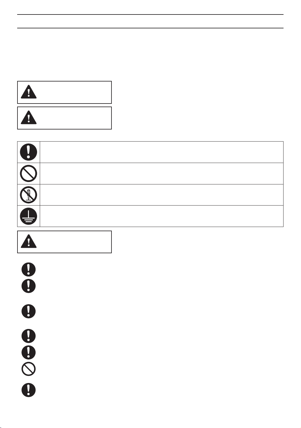
Explanation of symbol word panels
The following symbol word panels are used to classify and describe the level of hazard, injury, and
property damage caused when the denotation is disregarded and improper use is performed.
WARNING
CAUTION
The following symbols are used to classify and describe the type of instructions to be observed.
This symbol is used to alert users to a specific operating procedure that must be followed in
order to operate the unit safely.
This symbol is used to alert users to a specific operating procedure that must not be
performed.
This symbol is used to alert users not to disassemble the equipment.
This symbol is used to alert users to make sure of grounding when using the equipment with
the grounding terminal.
Denotes a potential hazard that could result in serious injury or
death.
Denotes a hazard that could result in minor injury.
WARNING
To reduce the risk of fire, electric shock or personal injury, observe the following:
Use this unit only in the manner intended by the manufacturer. If you have any questions,
contact the manufacturer.
Installation work and electrical wiring must be done by qualified person(s) in accordance with
all applicable codes and standards, including fire-rated construction.
Sufficient air is needed for proper combustion and exhausting of gases through the flue
(chimney) of fuel burning equipment to prevent backdrafting. Follow the heating equipment
manufacturer’s guidelines and safety standards such as those published by the National
Fire Protection Association (NFPA), the American Society for Heating Refrigeration and Air
Conditioning Engineers (ASHRAE) and the local code authorities.
When cutting or drilling into a wall or ceiling, do not damage electrical wiring and other
hidden utilities.
Ducted fans must always be vented to the outdoors.
Do not use this unit with any solid-state control device.
Before servicing or cleaning unit, switch power off at service panel and lock the service
disconnecting mains to prevent power from being switched on accidentally. When the service
disconnecting mains cannot be locked, securely, fasten a prominent warning device, such as a
tag, to the service panel.
2
Page 3
GENERAL SAFETY INFORMATION
WARNING
Not to be installed in a ceiling thermally insulated to a value greater than R40. (This is required
for installation in Canada only.)
Never place a switch where it can be reached from a tub or shower.
A statement to the effect that when the product is to no longer be used, it must not be left in
place but removed, to prevent it from possibly falling.
Do not disassemble the unit for reconstruction. It may cause fire or electric shock.
Ceiling joist must be subjected to static load more than five times the weight of the product.
This product must be grounded.
CAUTION
Do not install this In-Line Fan where the temperature may exceed 60℃(140°F).
Make certain that the service supply voltage is 120V, 60Hz.
Follow all local electrical and safety codes as well as
the National Electrical Code (NEC) and the Occupation
Safety and Health Act (OSHA).
Always switch the power source off before working on
or near the fan or motor.
Protect the electrical wires from sharp edges, oil, grease,
hot surfaces, chemicals, or other objects.
Do not bend the electrical wires.
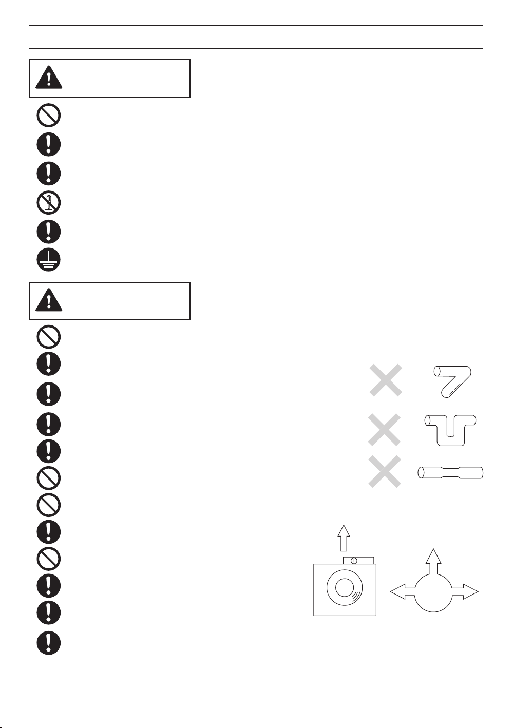
Do not install the unit where ducts are configured as
shown in Fig.A.
Provide suction parts with proper ventilation.
For general ventilating use only. Do not use to exhaust
hazardous or explosive materials or vapours.
Before installation, confirm that the unit is facing the
right direction. (Fig.B)
Do not drop the unit, put it on the hanger securely.
The special-purpose or dedicated parts, such as
mounting fixtures, must be used if such parts are
provided.
up
Fig.B
Fig.A
up
direction
up
3
Page 4
DESCRIPTION
These Panasonic In-Line Fan models use a sirocco fan driven by a capacitor motor.
The motor is designed to have an extended service life with reduced energy consumption, and a
reduced noise level.
It also incorporates a thermal cutout for safety.
UNPACKING
Unpack and carefully remove unit from carton.
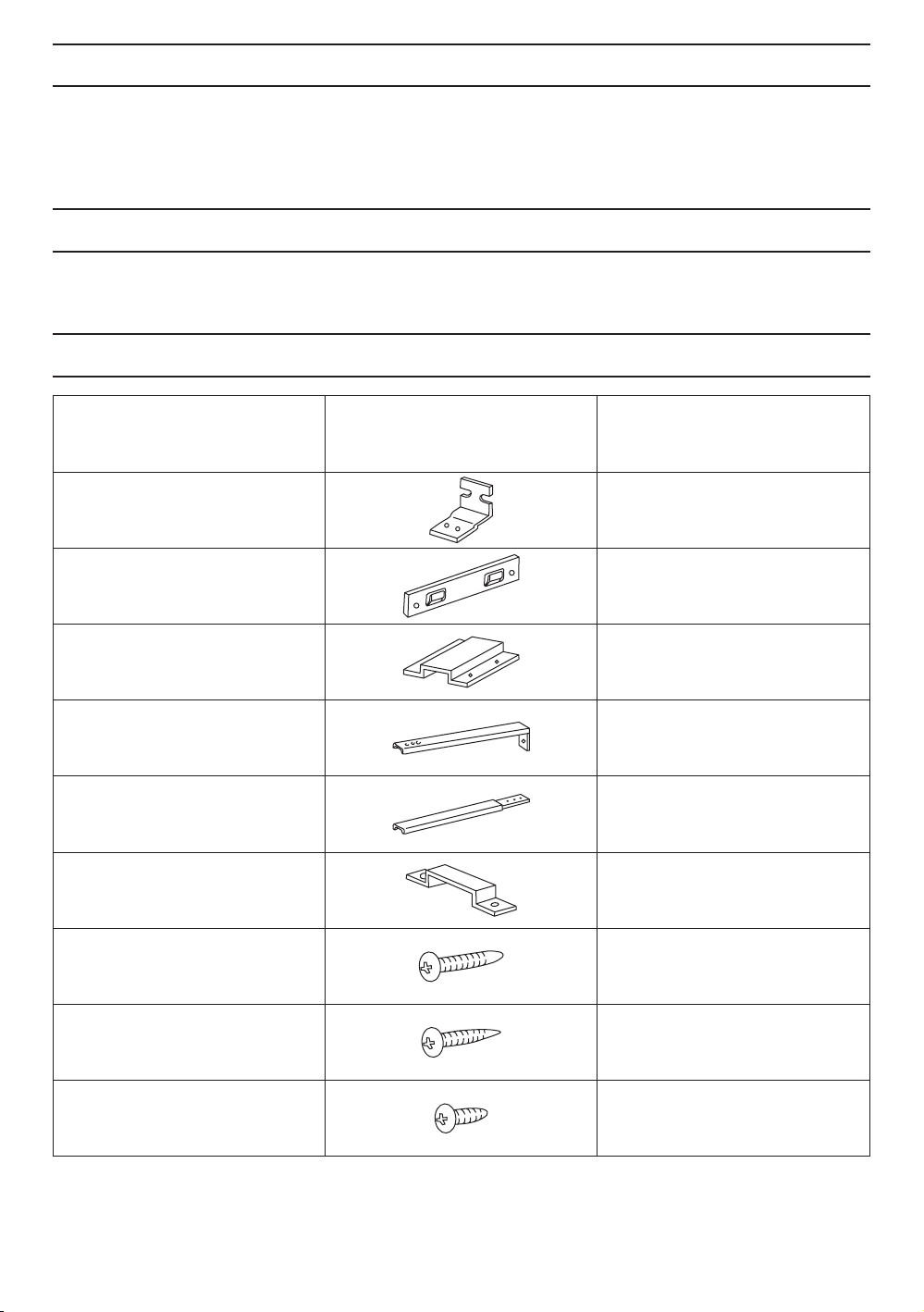
Refer to the supplied accessories list to verify that all parts are present.
SUPPLIED ACCESSORIES
Part name Illustration Quantity
Bracket 2
Hanger
Bracket cover
Installation bracket
Extension bracket
Holder
(Assembled on body)
Long screw
Self-tapping screw
Short screw
1
2
2
2
2
10
12
4
4
Page 5
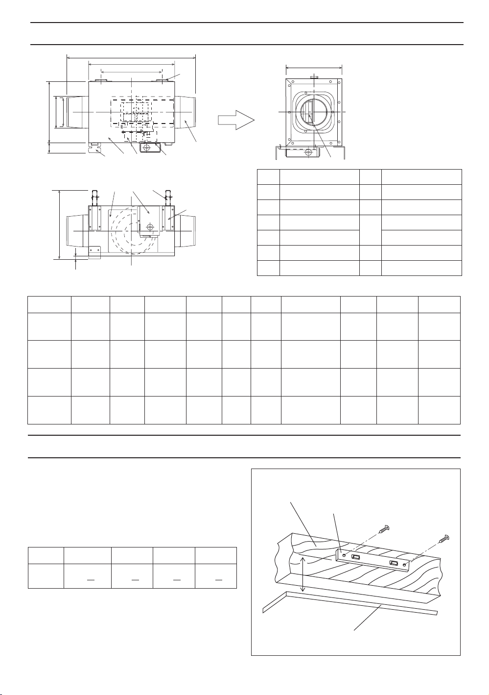
DIMENSIONS
C
B
E
D
A
H
I
J
G
F
Model No. A B C D E F G H I J
AIR FLOW
No. Part name No. Part name
Motor
Body
Adapter
Fan Extension bracket
Junction box
Junction box cover
Inspection panel
Bracket cover
Installation bracket
Bracket
Holder
Dimensions: mm(inch)
FV-10NLF1E
FV-20NLF1
FV-30NLF1
FV-40NLF1
340
(13 3/8)
340
(13 3/8)
390
(15 11/32)
420
(16 17/32)
240
(9 7/16)
240
(9 7/16)
270
(10 5/8)
340
(13 3/8)
440
(17 5/16)
550
(21 21/32)
600
(23 5/8)
560
(22 1/6)
200
(7 7/8)
240
(9 7/16)
280
(11 1/32)
280
(11 1/32)
38.1
(1 1/2)8 (5/16)
38.1
(1 1/2)8 (5/16)
38.1
(1 1/2)8 (5/16)
38.1
(1 1/2)8 (5/16)
321-581
(12 5/8-22 7/8)
321-621
(12 5/8-24 7/16)
321-661
(12 5/8-26)
321-661
(12 5/8-26)
242
(9 17/32)
242
(9 17/32)
242
(9 17/32)
242
(9 17/32)
INSTALLATION I (HORIZONTALLY BETWEEN JOISTS)
1. Disconnect the power to the receptacle before
starting the installation.
2. Fix the hanger to the ceiling joist. Keep
distance “A” between the hanger and ceiling
board (table 1). Use two long screws to fasten
the hanger. (Fig.1)
Dimension: mm(inch)
MODEL FV-10NLF1E FV-20NLF1 FV-30NLF1 FV-40NLF1
165
A
(6
1
)
2
165
(6
1
2
185
(7
1
4
)
215
)
(8
(table 1)
1
)
2
Ceiling joist
A
Hanger
Long Screw
97
∅
(∅3 13/16)
142
∅
(∅5 19/32)
142
∅
(∅5 19/32)
195
∅
(∅7 11/16)
112
∅
(∅4 13/32)
158
∅
(∅6 7/32)
158
∅
(∅6 7/32)
211
∅
(∅8 5/16)
Ceiling board
Fig. 1
5
Page 6
INSTALLATION I (HORIZONTALLY BETWEEN JOISTS)
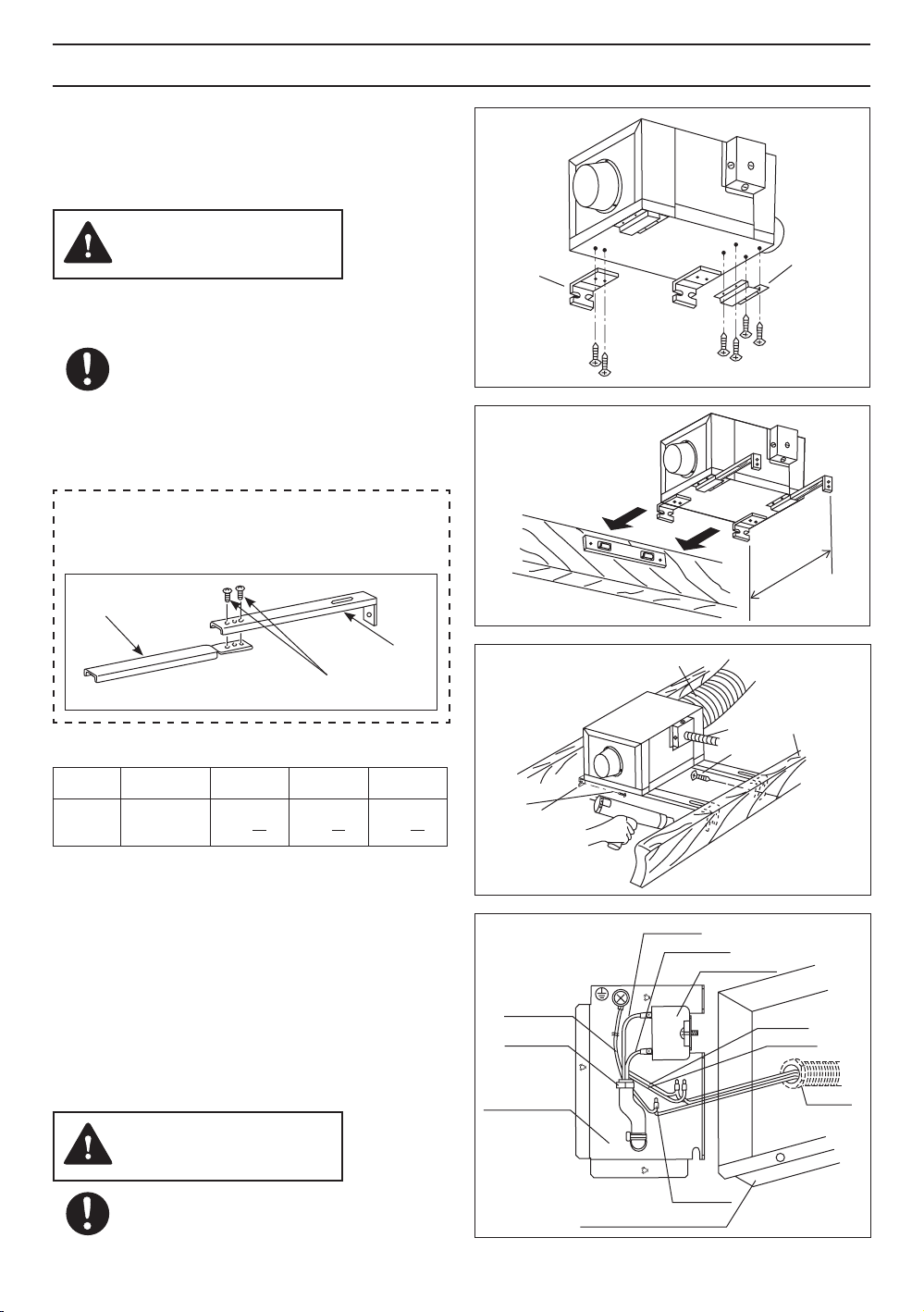
3. After confirming the direction that the unit
will be facing, attach the bracket and bracket
cover to the unit with self-tapping screws.
(Fig.2)
CAUTION
The holder was assembled on the back
side of the unit. (no shown in Fig.2)
Attach the unit body horizontally to the
panel of your choice.
For best results, the bracket and bracket
cover should be attached vertically.
The holder and the bracket should be
installed on the same side of the joist.
4. Insert installation bracket into bracket cover.
If joist space is greater than distance B at the
center (table 2), attach installation bracket and
extension bracket as shown below.
Extension
bracket
Installation
bracket
Short
screw
Dimension: mm(inch)
MODEL FV-10NLF1E FV-20NLF1 FV-30NLF1 FV-40NLF1
B
381
(15)
421
(16
1
2
461
(18
1
8
)
(table 2)
5. Insert the holder, located on the unit, into the
hanger. (Fig.3)
6. Attach the In-Line Fan to a joist or a pillar with
the long screws. (Fig.4)
7. Remove junction box cover and secure conduit
or wire holder to junction box cover knockout
hole. (Fig.5)
8. Using wire nuts, connect house power wire as
shown in the wiring diagram.
9. Replace junction box cover.
461
(18
1
)
8
)
Bracket
Long
Screw
Green wire
Cord clip
Junction box
Self-tapping
screws
Circular duct
Red wire
Blue wire
Conduit
Long
Screw
Condenser
White
Black
Bracket
cover
Fig. 2
B
Fig. 3
Ceilling
joist
Conduit
Fig.4
CAUTION
Mount junction box cover carefully so
that wires are not pinched.
Junction box cover
6
Wire nut
Fig.5
Page 7
INSTALLATION I (HORIZONTALLY BETWEEN JOISTS)
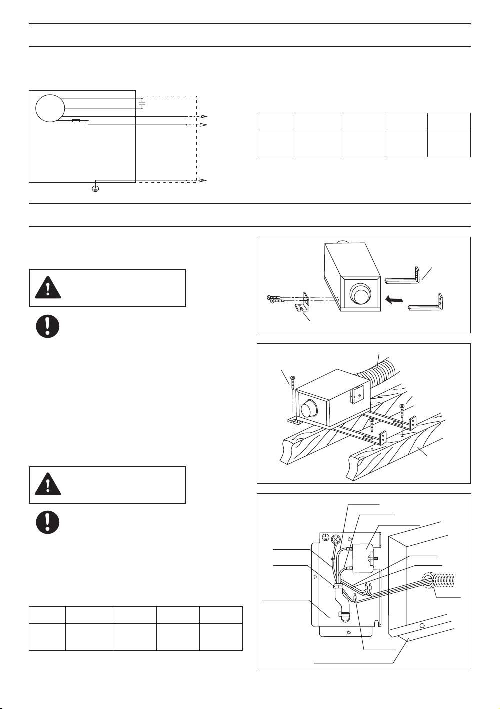
Wiring Diagram
Fan body
Motor
(Fuse in Motor
FV-10NLF1E:134°C
FV-20NLF1:167°C
FV-30NLF1:134°C
FV-40NLF1:134°C)
Thermally - protected
Blue
Red
White
Black
Earth ground
Junction box
Capacitor
Green
Power
Supply
120V
60Hz
G
~
10. Install circular ducts (on both ends) and secure
them with tape or clamps.
Consult table 3 for the appropriate duct sizes.
MODEL FV-10NLF1E FV-20NLF1 FV-30NLF1 FV-40NLF1
duct
∅
11. Connect power line to receptacle after finshing
duct work.
INSTALLATION II (ON CEILINGS/JOISTS)
1. Attach installation bracket and bracket to the
unit body. (Fig.6)
CAUTION
Insert the installation bracket into the
bracket cover attached to the panel.
2. Extend installation bracket and put the unit
on the ceiling or joist. Secure with long screws.
(Fig.7)
3. Remove junction box cover and secure conduit
or wire holder to junction box cover knockout
hole. (Fig.5)
4. Using wire nuts, connect house power wire as
shown in the wiring diagram on page 7.
5. Replace junction box cover.
Long screw
102
(4)
Bracket
152
(6)
(table 3)
Circular duct
Dimension: mm(inch)
152
(6)
203
(8)
Installation
bracket
Fig.6
Long screw
Ceiling joist
Fig.7
CAUTION
Mount junction box cover carefully so
that wires are not pinched.
6. Install circular ducts (on both ends) and secure
them with tape or clamps.
Consult table 3 for the appropriate duct sizes.
Dimension: mm(inch)
MODEL FV-10NLF1E FV-20NLF1 FV-30NLF1 FV-40NLF1
duct
∅
102
(4)
152
(6)
(table 3)
152
(6)
203
(8)
Green wire
Cord clip
Junction box
Red wire
Blue wire
Wire nut
Junction box cover
Condenser
White
Black
Conduit
Fig.5
7
Page 8
INSTALLATION III (VERTICALLY ON JOISTS OR PILLARS)
Installing the In-Line Fan requires an accessible
area (attic or air extraction apparatus)
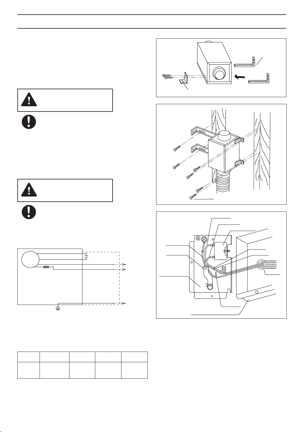
1. Install the In-Line Fan using the first step
described in INSTALLATION II.
2. Extend installation bracket and hang the unit
on the joist or piller. Fix with the long screws.
(Fig.8)
Installation
bracket
CAUTION
Be careful not to drop the unit.
3. Remove junction box cover and secure conduit
or wire holder to junction box cover knockout
hole. (Fig.5)
4. Using wire nuts, connect house power wire as
shown in the wiring diagram.
5. Replace junction box cover.
CAUTION
Mount junction box cover carefully so
that wires are not pinched.
Wiring Diagram
Fan body
Motor
(Fuse in Motor
FV-10NLF1E:134°C
FV-20NLF1:167°C
FV-30NLF1:134°C
FV-40NLF1:134°C)
Thermally - protected
Blue
Red
White
Black
Earth ground
6. Install circular ducts (on both ends) and secure
them with tape or clamps.
Consult table 3 for the appropriate duct sizes.
Junction box
Capacitor
Green
Power
Supply
120V
60Hz
G
~
Green wire
Cord clip
Junction box
Bracket
Junction box cover
Long screw
Red wire
Blue wire
Wire nut
Fig.6
Fig.8
Condenser
White
Black
Conduit
Fig.5
Dimension: mm(inch)
MODEL FV-10NLF1E FV-20NLF1 FV-30NLF1 FV-40NLF1
duct
∅
102
(4)
152
(6)
152
(6)
(table 3)
8
203
(8)
Page 9
MAINTENANCE
WARNING
Disconnect power line before proceeding
with repairs or maintenance.
CAUTION
Never use benzene based thinner or
similar chemicals for cleaning the In-Line
Fan.
Do not allow water to come into contact
with the motor.
Do not immerse resin parts in water where
the temperature is over 60℃ (140°F).
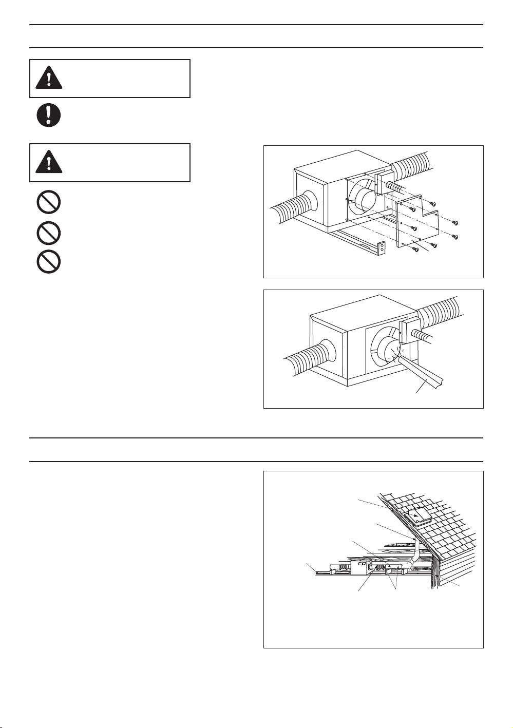
1. Remove inspection panel (take off the screws
and pull). (Fig.9)
2. Clean inspection panel (do not immerse in
water), wipe dry with cloth.
3. Remove dust and dirt inside the fan’s body
using a vacuum cleaner. (Fig.10)
4. Using a cloth dampened with kitchen
detergent, remove any dirt from the fan’s
body. Wipe dry with a cloth (do not wipe
thermal insulation parts inside body with
dampened cloth).
5. Replace inspection panel.
Cleaner
Inspection panal
Fig.9
Fig.10
PRACTICAL GUIDE TO INSTALLATION
Properly insulate the area around the fan to
minimize building heat loss and gain. (Fig.11)
Loose fill or batt insulation can be placed directly
over the fan housing in the attic. Our fans
and fan/light combination units do not create
excessive heat that is a common problem with
recessed light fixtures or some competitor’s fan/
light combination. Our efficient, cool-running
motors and our fluorescent lamps do not create
enough ambient heat to be subjected to these
limitations. The ducting from this fan to the
outside of the building has a strong effect on the
air flow, noise and energy use of the fan. Use
the shortest, straightest duct routing possible for
best performance, and avoid installing the fan
with smaller ducts than recommended. Insulation
around the ducts can reduce energy loss and
inhibit mold growth. Fans installed with existing
ducts may not achieve their rated air flow.
4, 6 or 8 inch roof jack,
wall cap, or soffit vent
with backdraft damper
Mechanically connect duct to
termination and seal with mastic
or approved foil faced tape
2-3 ft straight run before elbow
In attic installation,
caulk box to drywall
A short piece of flexible
duct helps alignment
and absorbs sound.
Use clamps plus mastic
or approved foil faced
tape at all flex joints.
Foil tape tightly
covers all metal
duct joints.
(Glue PVC joints)
Insulation
Fig.11
9
Page 10
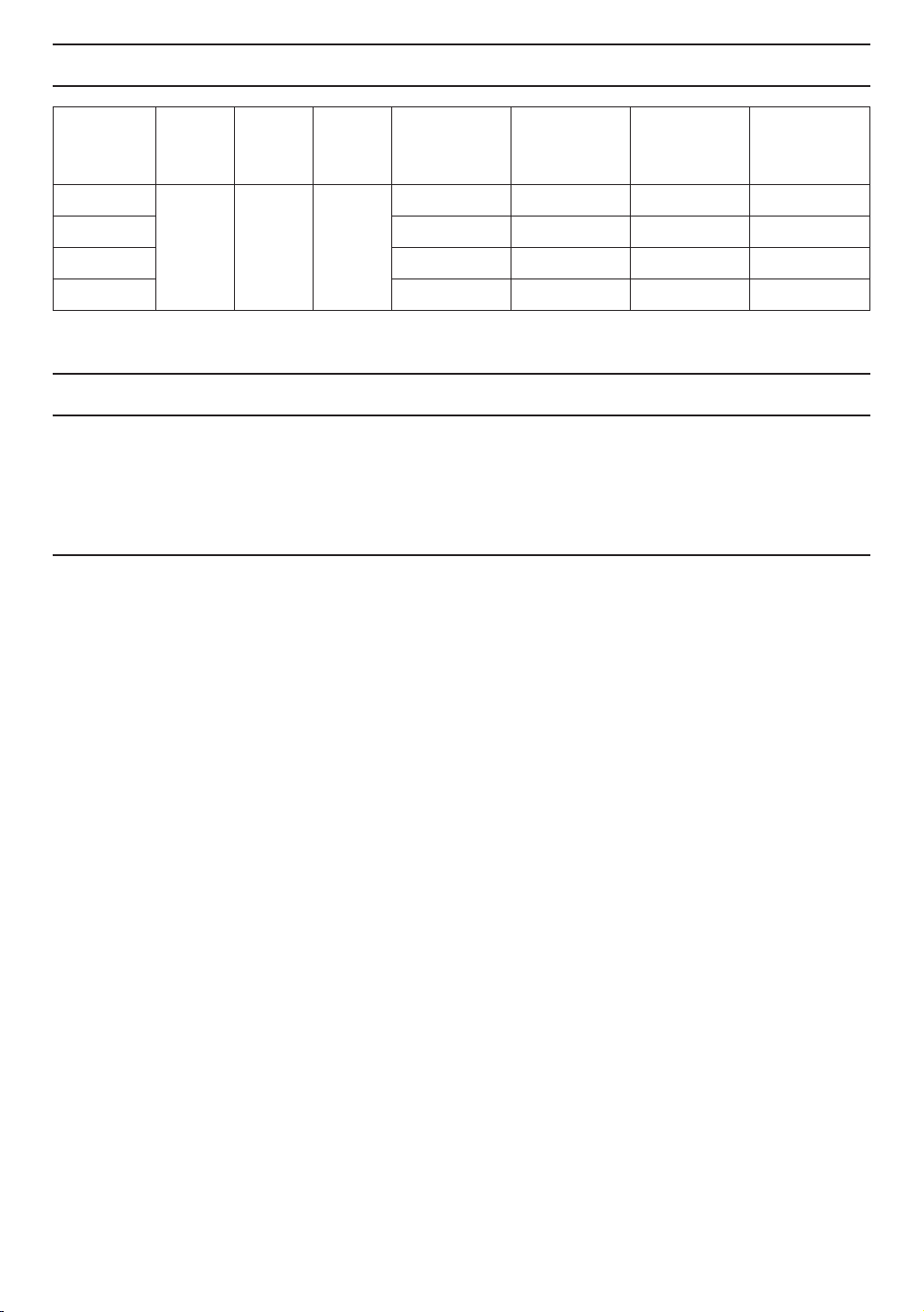
SPECIFICATIONS
Model No.
FV-10NLF1E
FV-20NLF1
FV-30NLF1
FV-40NLF1
*Power consumption, speed and air delivery values have been measured at 5mm WG (0.2’’ WG).
Air
direction
Exhaust 120 60
V Hz
Power
consumption
(W)
30 1510 120 6.3(13.9)
57 1260 240 7.5(16.5)
98 1340 340 10.9(24.1)
132 1150 440 11.9(26.3)
Speed
(PRM)
Air delivery
(CFM)
Weight
K
g
PRODUCT SERVICE
Warning Concerning Removal of Covers.
The unit should be serviced by qualified technicians only.
Your product is designed and manufactured to ensure a minimum of maintenace.
Should your unit require service or parts, call Panasonic Call Center at 1-866-292-7299(USA)
Or 1-800-669-5165(Canada).
Panasonic Corporation of North America
Two Riverfront Plaza, Newark, NJ 07102
www.panasonic.com
Panasonic Canada Inc.
5770 Ambler Drive, Mississauga, Ontario L4W 2T3
www.panasonic.ca
(lb.)
Panasonic Corporation 2002-2015
©
Printed in China
10
P0502-60915 10NLF10750F
 Loading...