

Page 1
INSTALLATION
INSTRUCTIONS
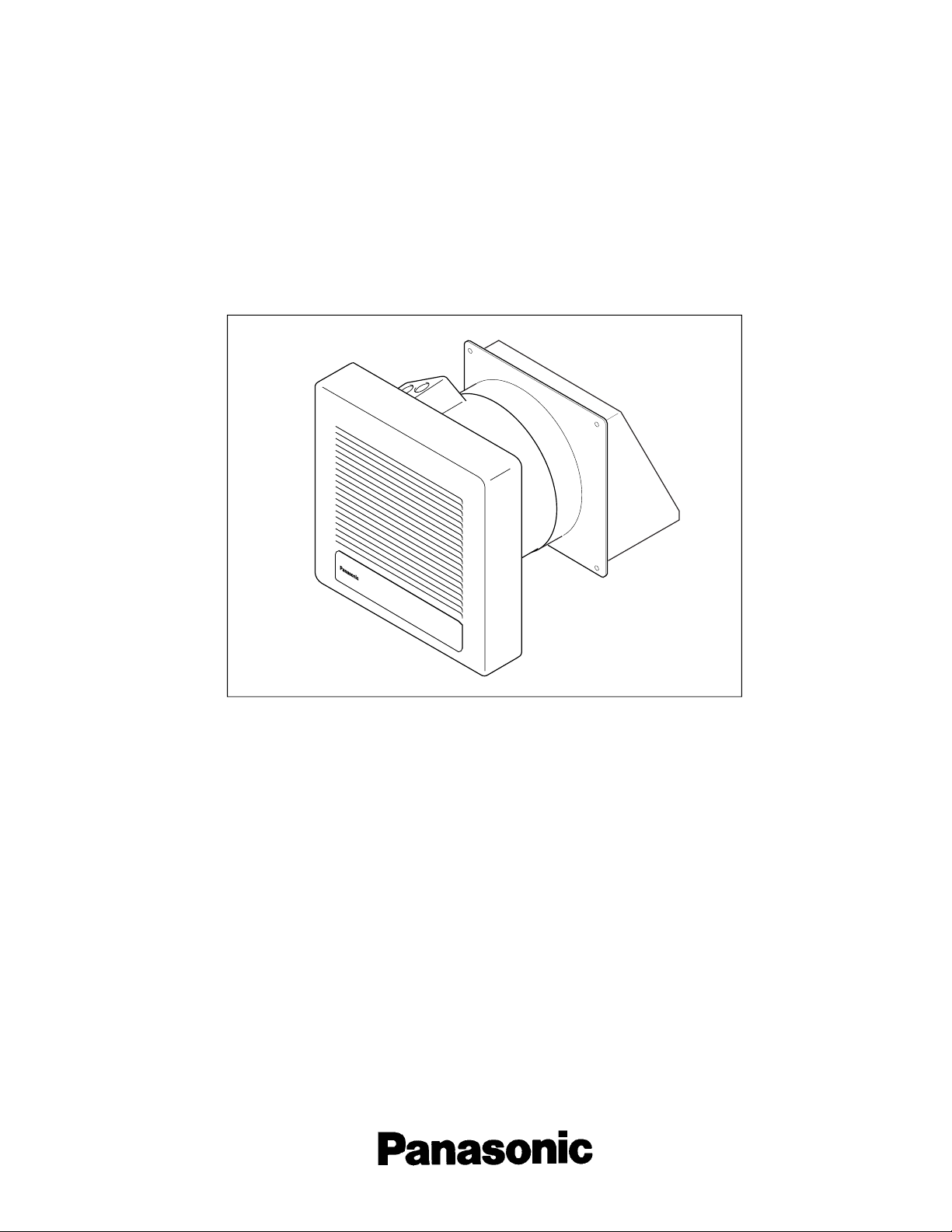
Through the Wall Fan "Whisper Wall"
Ventilating Fan
FV-08WQ1
READ AND SAVE THESE INSTRUCTIONS
Please read instructions carefully before attempting to install, operate or service the
Panasonic Ventilating Fan. Failure to comply with these instructions could result in personal
injury and/or property damage. Please retain for future reference.
Table of Contents Pages
List of components............................................................................................................ 2
Description ....................................................................................................................
Reference installation drawing.......................................................................................... 2
Dimensions .....................................................................................................................
Specifications.................................................................................................................
Unpacking ......................................................................................................................
General safety precautions............................................................................................... 4
Installation I (In new construction) .................................................................................... 5-6
Installation II (In remodeling) ............................................................................................ 7-8
Maintenance .....................................................................................................................9-10
Product Service.................................................................................................................10
....
...
...
2
..
3
4
4
Page 2
List of components
FV-08WQ1
Part name Drawing
Wall sleeve
Quantity
1
Part name Drawing
III (4 x 8)
Screw
Template (Pattern paper)
Screw I (4 x 30)
Mounting plate
Screw II (4 x 6) (for new
construction only)
4
1
2
Exterior hood
Externsion sleeve
Description
This Panasonic wall mounted ventilating fan uses a propeller fan driven by a capacitor motor.
The motor is designed for extended service life with reduced energy consumption.
It also incorporates a thermal-cutoff device for safety. The grille is easily detachable from the main unit.
Quantity
1
1
1
1
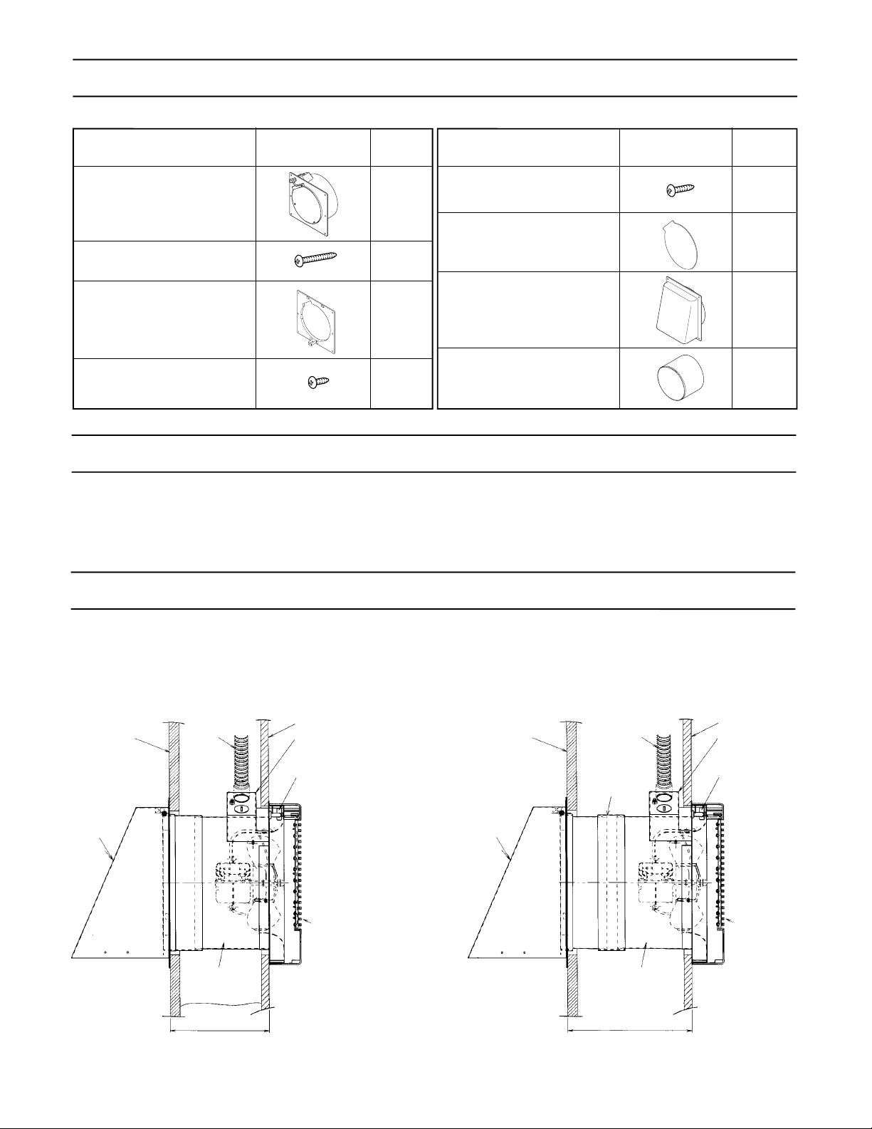
Reference installation drawing
When the wall thickness is between 152.4 mm (6") and 254 mm (10"), mount the extension
sleeve as shown below. When the wall thickness is more than 254 mm (10"), prepare an
extension sleeve with an inner diameter of 207 mm (8 5/32") and a length of wall thickness
minus 127 mm (5"), and mount it as shown below. (The seam should be covered with
aluminum tape.)
Main unit
Indoor
Exterior wall
Exterior
hood
Outdoor
Wall thickness: 114.3 - 152.4 mm (4.5 - 6")
No extension sleeve is used.
Flexible
conduit
Wall sleeve
Interior wall
Junction box
Connector
Exterior wall
Exterior
hood
Outdoor
Flexible conduit
Extension
sleeve
Wall sleeve
Interior wall
Junction box
Connector
Main unit
Indoor
Wall
thickness
Wall
thickness
2
Page 3
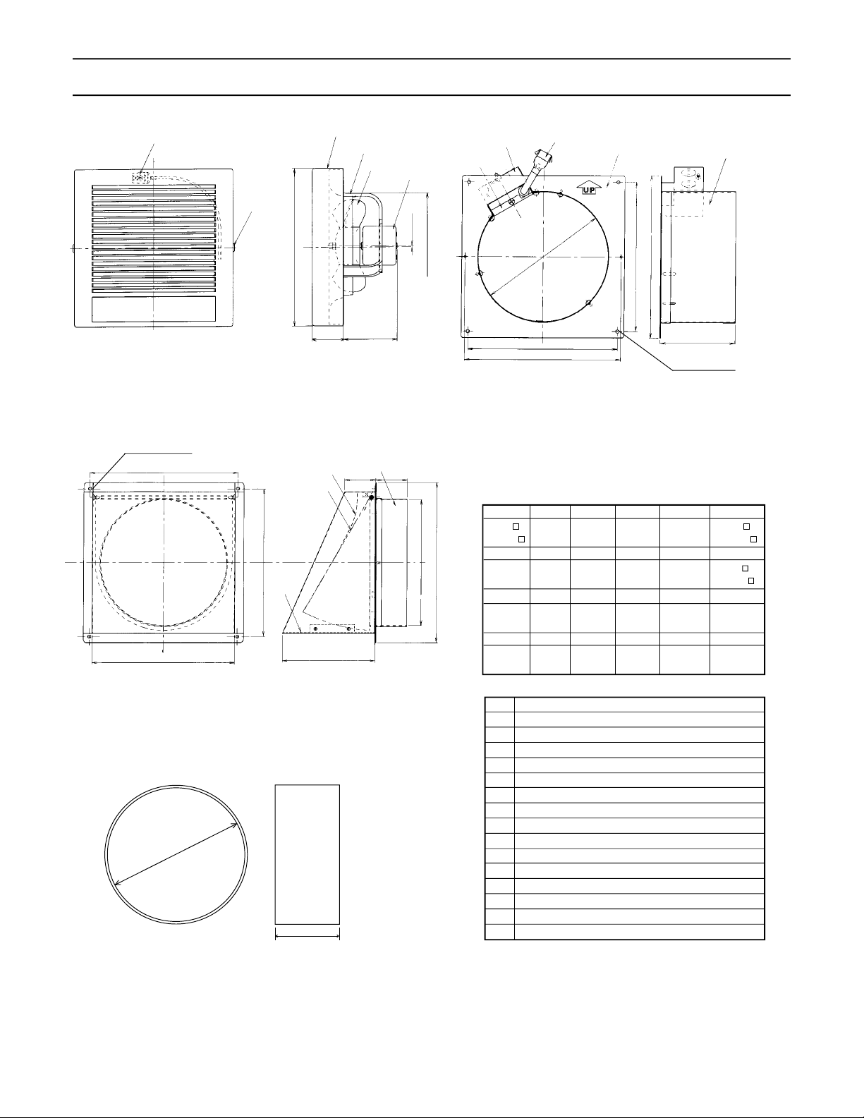
Dimensions
Main unit
Exterior hood
4-5 dia. hole
Wall sleeve
5
6
S
R
15
Q
1
2
3
4
D
A
14
P
C
13
O
B
12
E
N
L
M
9
10
ABCD E F
260
(10-1/4 ) (2-1/16) (3-15/32) (3/32) (6-13/16ø) (9-27/32
GH I J K L
115 203 240 230 230 260
(4-17/32) (8) (9-7/16) (9-1/16) (9-1/16) (10-1/4
MNO P Q R
204ø 50 50 150 230 240
(8-1/32ø) (31/32) (31/32) (5-29/32) (9-1/16) (9-7/16)
STU
240 207 127
(9-7/16) (8-5/32) (5)
11
H
J
I
52 88 2 173ø 250
7
K
F
G
4-5 dia. hole
Unit: mm (inch)
8
)
)
Extension sleeve
T
No. Part name
1 Grille
2 Frame
3 Blade
4 Motor
5 Connector
6 Hook
7 Flange
8 Duct
9 Junction box
10 Junction box cover
11 Connector
12 Shutter
13 Duct
U
14 Spring
15 Bird screen
3
Page 4

Specifications
Model Air direction V Hz Power consumption
FV-08WQ1 Exhaust 120 60 17 1340 70 1.1 3.1
*1
At 0.0" Static pressure, (Pa)
*2
For main unit only.
*1
(W) Speed
(r/min.)
*1
Air delivery at 0.03"WG Noise Weight
(CFM) lb. (kg)
*2
(1.4)
Unpacking
Unpack and carefully remove unit from the carton. Refer to list of components to verify that all parts were supplied.
General safety precautions
1. Do not install this ventilating fan where air temperature may exceed 104 °F. (40 °C)
2. Make certain that the nominal service voltage is 120V 60 Hz.
3. Follow all local electrical and safety codes, as well as the National Electrical Code (NEC) and the Occupation Safety and Hea
Act (OSHA).
4. Always disconnect the power source before working on or near the fan, motor or junction box.
5. Protect the power cord from sharp edges, oil, grease, hot surfaces, chemicals, or other objects.
6. Do not kink the power cord.
7. Provide suction parts with proper ventilation.
(Cooking area)
Do not install above or
inside this area.
8. This unit is acceptable for use over a bathtub or shower when
installed in a GFCI protected branch circuit.
lth
CAUTION:
1. For general ventilating use only. Do not use to exhaust hazardous or explosive materials and vapors.
2. Not for use in cooking area. (Fig. A)
Cooking
equipment
Floor
3. This product must be grounded.
4. To reduce the r isk of injur y to persons , install fan at least 7 - 10
Fig. A
feet (2.1 - 3.05 meters) above the floor.
WARNING:
To reduce the risk of fire, electric shock, or injury to persons, observe the following;
A.Use this unit only in the manner intended by the manufacturer. If you have any questions, contact the manufacturer.
B.Installation work and electrical wiring must be done by qualified person(s) in accordance with all applicable codes and
standards, including fire-rated construction.
C.Sufficient air is needed for proper combustion and exhausting of gases through the flue (chimney) of fuel burning
equipment to prevent backdrafting. Follow the heating equipment manufacturer's guideline and safety standards such
as those published by the National Fire Protection Association (NFPA), and the American Society for Heating Refriger ation and Air Conditioning Engineers (ASHRAE), and the local code authorities.
D.When cutting or drilling into wall or ceiling, do not damage electrical wiring and other hidden utilities.
E.If this unit is to be installed over a tub or shower, it must be marked as appropriate for the application.
F. Do not use this fan with any solid-state speed control device.
G.Before servicing or cleaning unit, s witch po wer off at service panel and lock the service disconnecting means to prevent
power from being switched on accidentally. When the service disconnecting means cannot be locked, securely fasten
a prominent warning device, such as a tag, to the service panel.
H.NEVER place a switch where it can be reached from a tub or shower.
4
Page 5

Installation I (In new construction)
NOTE:
If the wall thickness is more than 152.4 mm (6"), refer to the
reference installation drawing when the wall thickness is more
than 152.4 mm (6") on page 2. However, this ventilating fan
can be installed on an interior wall with a thickness of 12.7 –
16 mm (1/2 – 5/8”). For installation on other walls, refer to
the method on page 7, Installation II.
Exterior wall
1. Cut a 215 mm (8 1/2”) diameter hole in the wall. (Fig. 1)
(Cut the hole next to a wall stud as shown in the figure.).
2.
Adjust position of the flange on the wall sleeve (Fig. 2).
Loosen the three screws (arrow pointed) and slide the wall
sleeve horizontally to adjust its position to compensate for
the thickness of the interior wall (A). When this has been
done, tighten all three screws.
3. After providing a 3 mm notch in the wall stud, secure the flange
to the wall stud with supplied screws (Screw I). (Fig. 3)
4. Remove the junction box cover by removing screw (B).
5. Remove one of the knockout holes in the junction box.
8 1/2”
diameter
Flange
Wall sleeve
1/8"
3 mm
A
Knockout hole
Stud
Fig. 1
Fig. 2
Wiring Diagram
Switch (Availab le
on the market)
Power supply
AC 120 V 60 Hz
Earth ground
Motor
Junction box
White
Black
Red
Green
Green
6. Refer to the wiring diagram above.
Using the wire nuts, connect the house power wires to
ventilating fan wires.
(Fig. 4): black to black; white to white; green to greens.
Reattach the junction box cover.
CAUTION:
Reattach the junction box cover carefully so that the lead
wires are not pinched by the cover.
B
Hole in the wall
Fig. 3
Flexible conduit
Connector
Black
Green
White
Fig. 4
5
Page 6

Installation I (In new construction) - continue
7. Insert the attached exterior hood from the outside to cover
the wall sleeve, and secure it with four screws or nails.
Cover the seam between the wall sleeve and exterior
hood with aluminum tape, and apply mortar or caulking
around the exterior hood flange to prevent rainwater from
coming in. (Fig. 5)
Exterior hood
8. Using enclosed template (pattern paper), mark and cut
the opening in the interior wall cover. (Fig. 6)
9. Press the mounting plate tightly against the wall and secure to the outside of the wall sleeve with the supplied
screws(screw II). (Fig. 7)
10. Remove the grille from the fan unit.
Press the spring locks on the sides and pull the grille
back. (Fig. 8)
Aluminum
tape
Interior wall
material
Seam
Finish with mortar
or caulk.
Grille
Fan unit
(Frame)
Fig. 5
Fig. 6
Fig. 7
11. Attach the electrical connectors to each other, hook the
frame latches onto the mounting plate latch, and secure
the fan unit to the mounting plate with the supplied screw
(screw III). (Fig 9)
CAUTION:
Do not pinch the power cord with the frame.
12. Reattach the grille to the frame.
CAUTION:
Press on the grille until it clicks.
NOTE:
Be sure to paint the exterior hood. Before painting, thoroughly wipe off any oil on the surface . Also make sure that
the paint does not enter inside of the hood.
Fig. 8
Latch
Latch
Frame
Grille
Mounting plate
Fig. 9
6
Page 7

Installation II (In remodeling)
NOTE:
If the wall thickness is more than 152.4 mm (6"), refer to the
reference installation drawing when the wall thickness is
more than 152.4 mm (6") on page 2.
1. Cut holes in the interior and exterior walls. (Fig. 10)
Cut a hole in the interior wall using the attached template
(pattern paper), and make a 215 mm (8 1/2”) hole in the
exterior wall.
CAUTION:
The hole should be made in an area where pipes, cables
and telephone lines are not run, and there are no studs in
the way.
Hole in the
interior wall
Hole in the
exterior wall
Fig. 10
2. Lay interior wiring through the wall using a flexible conduit.
3. Remove the junction box from the wall sleeve by removing two screws (C). (Fig. 11)
4. Remove the junction box cover by removing screw (B).
5. Remove the screws (D) and replace the wall sleeve flange
with the mounting flange. (The mounting plate face should
align with the end of the wall sleeve which is protruding
from indoor side.)
6. Attach the wall sleeve to the wall with supplied screws
(Screw I). (Fig. 12)
If the interior wall material is plaster board, use appropriate fasteners (locally available) to secure the wall sleeve.
Junction box
B
A hole where the junction
box was attached to the
wall sleeve.
Flange
Wall sleeve
D
C
Mounting plate
Fig. 11
Fasterners,
etc.
Mounting plate
Fig. 12
7
Page 8

Installation II (In remodeling) - continued
7. Insert the attached exterior hood from the outside to cover
the wall sleeve, and secure it with four screws or nails.
Cover the seam between the wall sleeve and exterior hood
with aluminum tape, and apply mortar or caulking around
the exterior hood flange to prevent rainwater from coming in. (Fig. 13)
8. Pull the flexible conduit through the hole where the junction box was attached to the wall sleeve. (Fig. 14)
Exterior hood
9. Remove the knockout hole in the junction box and secure one end of the flexible conduit to the junction box.
Wiring Diagram
Switch (Available on
the market)
Power supply
AC 120 V 60 Hz
Earth ground
Motor
Junction box
White
Black
Red
Green
Green
10. Refer to the wiring diagram above. Using the wire nuts,
connect the house power wires to ventilating fan wires.
(Fig. 4 on page 5): black to black; white to white; green
to greens.
11. Place the junction box in its original position in the wall
sleeve and reattach the box cover. (Fig. 15)
Aluminum
tape
Flexible conduit
Seam
Finish with mortar
or caulk.
Fig. 13
Fig. 14
CAUTION:
Reattach the junction box cover carefully so that the lead
wires are not pinched by the cover.
12. Remove the grille from the fan unit. (Fig. 8 on page 6)
13. Attach the electrical connectors to each other, hook the
frame latches onto the mounting plate latch, and secure
the fan unit to the mounting plate with the supplied screw
(screw III). (Fig 16)
14. Reattach the grille to the frame.
CAUTION:
Press on the grille until it clicks.
NOTE:
Be sure to paint the exterior hood. Before painting, thor-
oughly wipe off any oil on the surface. Also make sure that
the paint does not enter inside of the hood.
Fig. 15
Latch
Latch
Frame
Grille
Mounting plate
Fig. 16
8
Page 9

Maintenance
WARNING:
Turn off the units power before performing maintenance. Perform maintenance procedure monthly.
CAUTION:
1. Never use gasoline, benzene, paint thinner or other similar chemicals for cleaning the ventilating fan.
2. Do not allow water to enter the motor and motor compartment.
3. Do not immerse resin parts in water with temperature higher than 140
1. Remove the grille (Hold the grille and press the hooks on
each side simultaneously. Pull the grille straight out from
the wall.) (Fig. 17)
o
F (60oC).
Grille
Fan unit
(Frame)
2. Wash and clean the grille (Use non-abrasive kitchen detergent). Wipe it dry with a clean cloth. (Fig. 18)
3. Remove dust and dirt from the fan blades and body using a vacuum cleaner. (Fig. 19)
.
Vacuum
cleaner
Fan unit
(Frame)
Blade
Fig. 17
Fig. 18
Fig. 19
9
Page 10

Maintenance - continued
4. Using a cloth dampened with a non-abrasive kitchen detergent, remove any dir t from the fan blades and body.
Wipe them dry with a clean cloth. (Fig. 20)
5. Reattach the grille.
CAUTION:
Press on the grille until it clicks.
Blade
Fan unit
(Frame)
Fig. 20
Product service
Warning concerning removal of covers.
This unit should be serviced by qualified technicians only. No service information is provided for customers. Your product is
designed and manuf actured to ensure a minimum of maintenance. However, should your unit ever require service, a nationwide system of factory service centers and AUTHORIZED INDEPENDENT SERVICE CENTER is maintained to support your
product's warranty. (In the U.S.A., call 1-800-545-2672 to locate the PASC Authorized Service Center nearest you.)
PANASONIC HOME AND COMMERCIAL PRODUCTS COMPANY
One Panasonic Way, Secaucus, NJ 07094
PANASONIC CANADA INC.
5770 Ambler Drive, Mississauga, Ontario L4W 2T3
10
Printed in Japan
08WQ14021D-I0298-4
 Loading...