

Panasonic FV-OSVQS, FV-08VQS, FV-11VQ5, FV-15VQS Installation Instructions Manual
PanasoniC
Ventilating
Fan
INSTALLATION
INSTRUCTIONS
Model No.
FV-OSVQS
FV-08VQS
FV-11VQ5
FV-15VQS
READ
AND
SAVE
THESE
INSTRUCTIONS
Thank you very much
for
having purchased our Ventilating
Fan.
Please
read these instructions carefully before attempting
to
install,
operate
or
service the Panasonic Ventilating
Fan.
Failure
to
comply
with
instructions could result
in
personal injury
and/or
property
damage.
Please
retain this booklet
for
future reference
Table
of
Contents
Unpacking ································································································· 2
Supplied Accessories .................................................................................... 2
Description .................................................................................................... 2
General Safety Information ............................................................................. 3
Dimensions .. ..
..
. . . . . . . . .
.. .. .. .. .. .. .. .. .. .. .. .. .. .. ..
..
. . . . . . . . . .
..
.. .. .. .. .. .. .. .. .. .. .. .. .. ..
..
. . . . . . . . . .
..
4
Wiring Diagram . . . . . . . . .
.. .. .. .. .. .. .. .. .. .. .. .. .. .. ..
..
. . . . . . . . . .
..
.. .. .. .. .. .. .. .. .. .. .. .. .. ..
..
. . . . . . . . . .
..
4
Installation
I (Joist Mounting -I)................................................................... 5-6
Installation
II
(Suspension Brackets Mounting).................................................. 7-8
Installation
III
(Joist Mounting
-II)
....... ....... ....... ....... ....... ....... .............. ....... ...... 8
Maintenance (Cleaning) ......... ·
..
· · ........ ·
..
· · ........ ·
..
· · ............ · ............ ·..........
8-9
Practical Guide To Installation · ....... · ....... · · ....... · ........ · ....... · · ....... · ....... · · ....... · ... 9
Specifications . . . . . . . . . . . . . . . . . . . . . . . . . . . . . . . . . . . . . . . . . . . . . . . . . . . . . . . . . . . . . . . . . . . . . . . . . . . . . . . . . . . . . . . . . . . . . . . . 1 0
Product
Service
.............................................................................................
10
UNPACKING
Unpack and carefully remove
the
unit
from
carton.
Refer
to
the
Supplied Accessories list
to
verify
that
all parts are present.
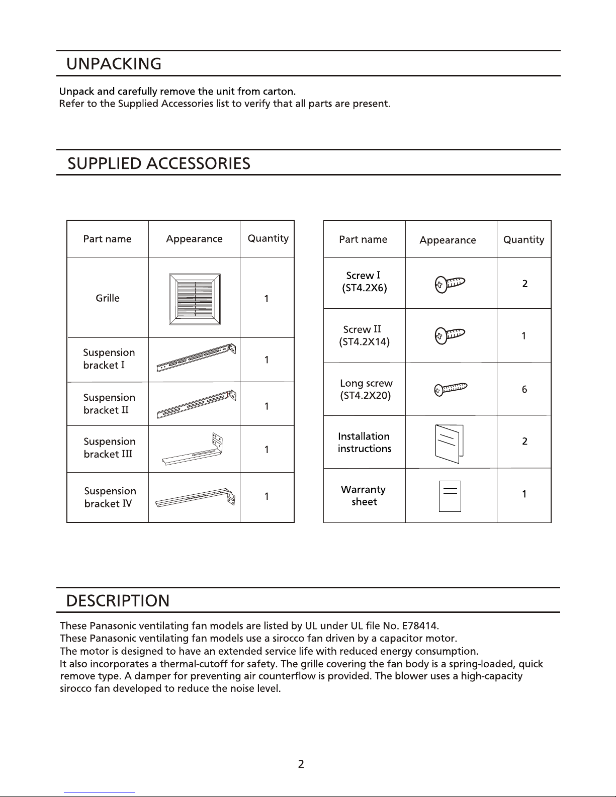
SUPPLIED
ACCESSORIES
Part name
Appearance
Quantity
Part name
Appearance
Grille
Screw!
~
(ST4.2X6)
Suspension
~
1
bracket I
=
~
Screw
II
~
(ST4.2X14)
Suspension
~
1
bracket
II
Long screw
~
(ST4.2X20)
Suspension
~
1
bracket
III
Installation
tj
instructions
Suspension
~
1
bracket'N
Warranty
0
sheet
DESCRIPTION
These Panasonic ventilating
fan
models are listed
by
UL
under
UL
file No. E78414.
These Panasonic ventilating
fan
models
use
a sirocco fan driven
by
a capacitor
motor.
The
motor
is
designed
to
have an extended service life
with
reduced energy consumption.
Quantity
2
1
6
2
1
It
also incorporates a thermal-cutoff
for
safety. The grille covering
the
fan
body
is
a spring-loaded, quick
remove type. A damper
for
preventing air
counterflow
is
provided. The
blower
uses
a high-capacity
sirocco
fan
developed
to
reduce
the
noise level.
2
GENERAL
SAFETY
INFORMATION
1.
Do
not
install this ventilating
fan
where interior room temperature may exceed
104'F (40'
C).
2. Make sure
that
the
electric service supply voltage
is
AC 120V, 60Hz.
3. Follow all local electrical and safety codes,
as
well
as
the
National Electrical Code
(NEC)
and
the
Occupation Safety and Health
Act
(OSHA).
4. Always disconnect
the
power
source before
working
on
or
near
the
fan, motor,
junction box.
5. Protect
the
power
cord
from
sharp edges, oil, grease,
hot
surfaces, chemicals
or
other
objects.
6. Do
not
kink
the
power
cord.
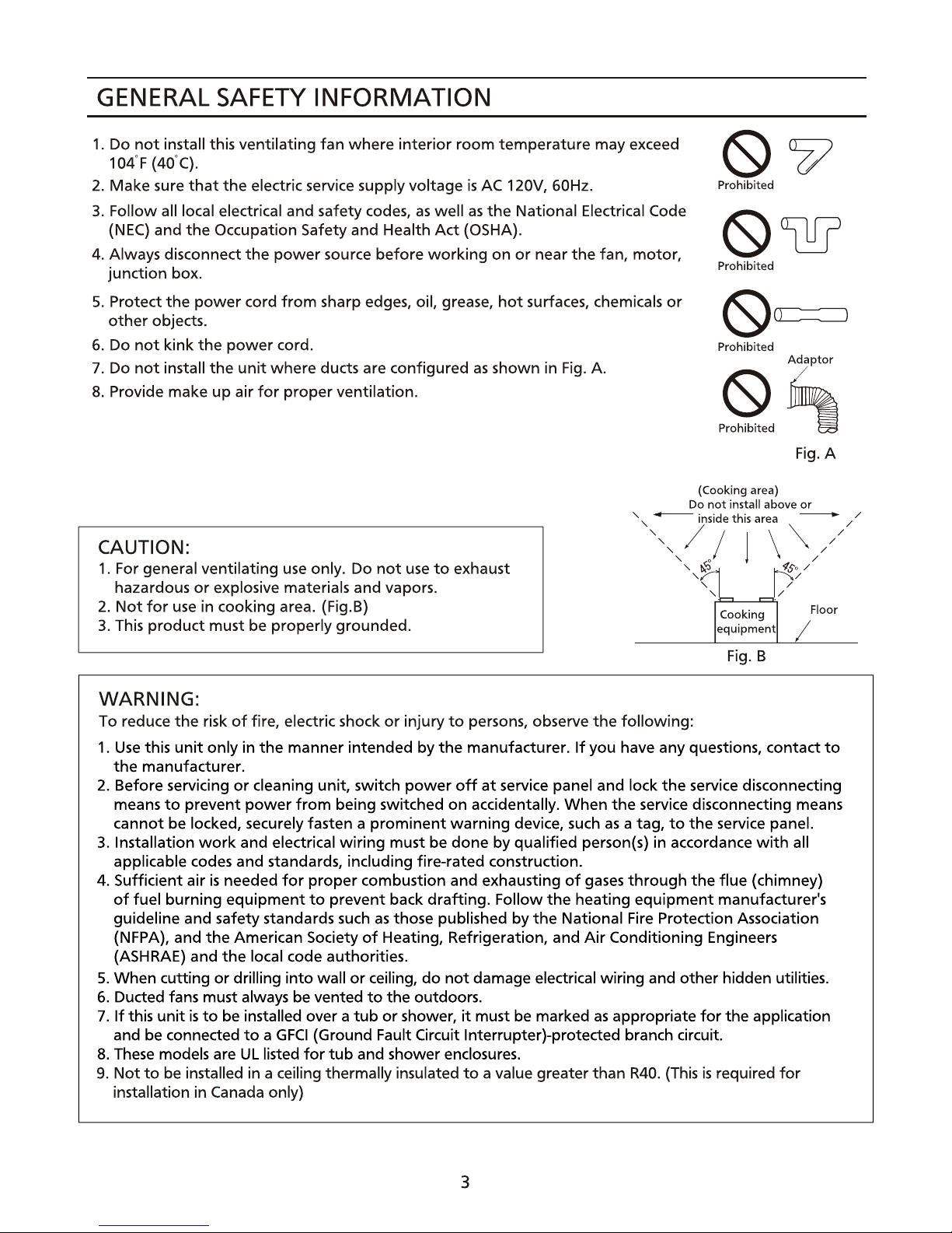
7. Do
not
install
the
unit
where ducts are configured
as
shown in
Fig.
A.
8. Provide make
up
air
for
proper
ventilation.
<9~
Prohibited
(S)W
Prohibited
<9~
Prohibited
§2~
Fig.
A
(Cooking area)
Do
not
install above
or
' - inside this area - /
',,,
/ I 1 \
"'
//
CAUTION:
1.
For general ventilating
use
only. Do
not
use
to
exhaust
hazardous
or
explosive materials and vapors.
',
~
fs. /
' /
2.
Not
for
use
in
cooking area. (Fig.B)
3.
This product must be properly grounded.
WARNING:
To reduce
the
risk
of
fire, electric shock
or
injury
to
persons, observe
the
following:
Cooking
equipment
Fig.
B
Floor
1.
Use
this
unit
only
in
the
manner intended
by
the
manufacturer.
If
you have any questions, contact
to
the
manufacturer.
2. Before servicing
or
cleaning
unit,
switch
power
off
at
service panel and lock
the
service disconnecting
means
to
prevent
power
from
being switched
on
accidentally. When
the
service disconnecting means
cannot be locked, securely fasten a
prominent
warning
device,
such
as
a tag,
to
the
service panel.
3. Installation
work
and electrical
wiring
must be done
by
qualified person(s) in accordance
with
all
applicable codes and standards, including fire-rated construction.
4.
Sufficient air
is
needed
for
proper
combustion and exhausting
of
gases
through
the
flue
(chimney)
of
fuel
burning equipment
to
prevent back drafting. Follow
the
heating equipment manufacturer's
guideline and safety standards
such
as
those published by
the
National Fire Protection Association
(NFPA), and
the
American Society
of
Heating, Refrigeration, and
Air
Conditioning Engineers
(ASH
RAE)
and
the
local code authorities.
5.
When cutting
or
drilling into wall
or
ceiling,
do
not
damage electrical wiring and
other
hidden utilities.
6. Ducted fans must always be vented
to
the
outdoors.
7.
If
this unit
is
to
be installed over a
tub
or
shower,
it
must
be
marked
as
appropriate
for
the
application
and be connected
to a GFCI
(Ground Fault Circuit lnterrupter)-protected branch circuit.
8. These models are
UL
listed
for
tub
and shower enclosures.
9.
Not
to
be installed in a ceiling thermally insulated
to
a value greater
than
R40.
(This
is
required
for
installation in Canada only)
3
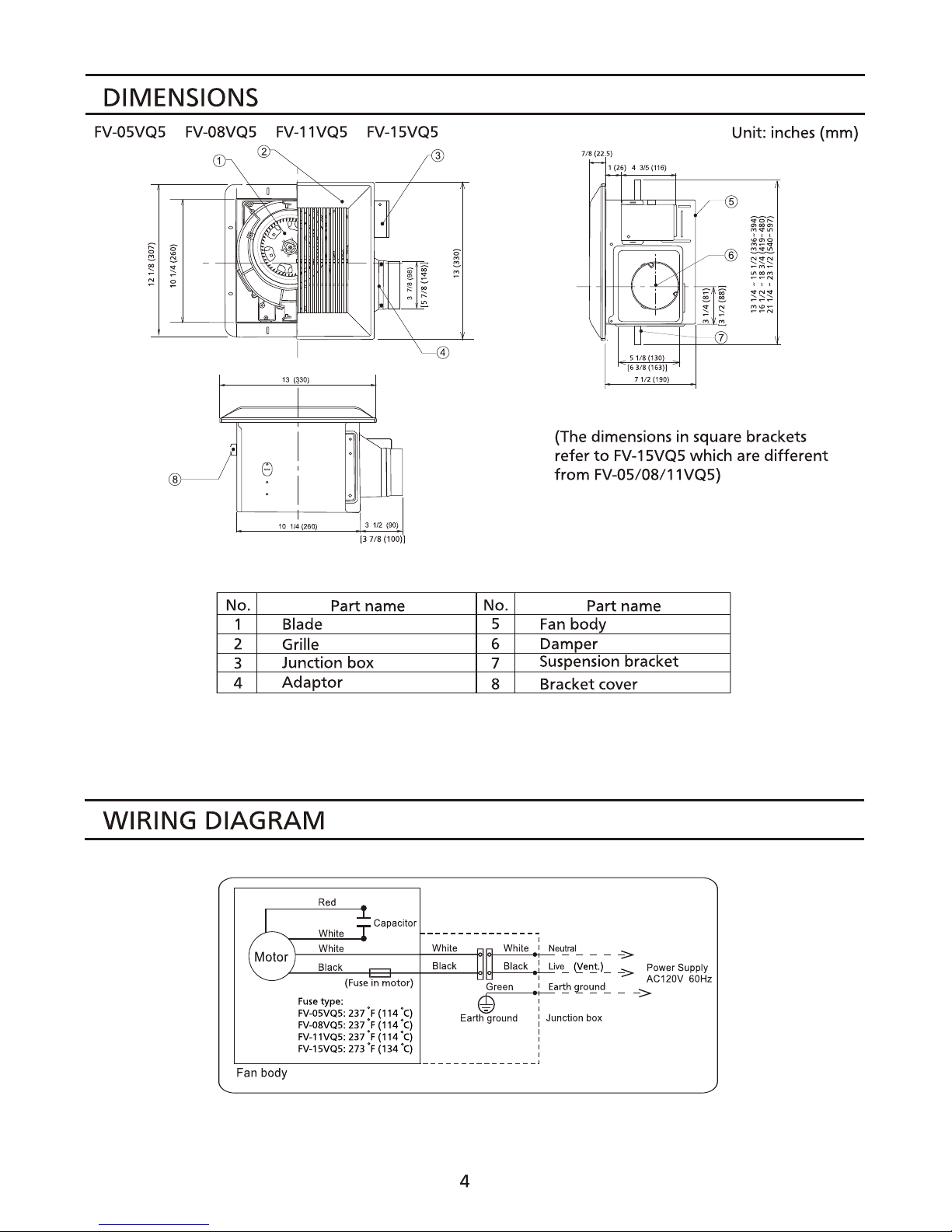
DIMENSIONS
FV-05VQ5 FV-08VQ5 FV-11VQ5 FV-15VQ5
Unit: inches (mm)
(The dimensions in square brackets
refer
to
FV-15VQ5 which are
different
from
FV-05/08/11VQ5)
(31111(100)1
No.
Part name
No.
Part name
1 Blade
5
Fan
body
2 Grille 6
Dam__l!er
3
Junction
box
7
Suspension bracket
4
Adaptor
8 Bracket cover
WIRING DIAGRAM
capacitor
r-~~-------+-W~h~lm~-M~~~W~h~lm~:~~~
~
Black
Black
Black
::
~
~e~.)
=
~
Powar
Supply
~____:=~--i':3--+-=;;.;.._-+ti+-'=:...t-,-=
AC120V
60Hz
(Fuse
in
motor) Green
.:
Ear!!J
i..fD!!..nd
_ _
->
Fuse
type: e :
FV~5VQ5:
237
'F (1
14
'c)
Earth
ground
,'
Junction
box
FV.{)8VQ5:
237
•F
(1
14
'
C)
FV-11VQ5:
237
'F(114
'
C)
:
FV-1
5VQ5:
273
'F
(134
'
C)
:
'::-------:----:-------__J---------------'
Fan
body
4
 Loading...