

Page 1
PEG1311049CE
Version:1401
Service Manual
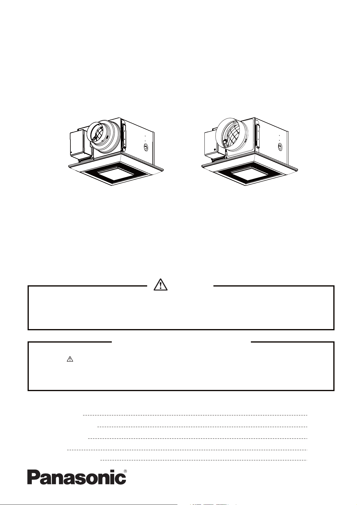
Ventilating Fan
WhisperLite
(North America Market)
TM
FV-08VQL5
FV-15VQL5
FV-11VQL5
WARNING
This service information is designed for experienced repair technicians only and is not designed for use by
the general public. It does not contain warnings or cautions to advise non-technical individuals of potential
dangers in attempting to service a product. Products powered by electricity should be serviced or repaired
only by experienced professional technicians. Any attempt to service or repair the product or products dealt
with in this service information by anyone else could result in serious injury or death.
IMPORTANT SAFETY NOTICE
There are special components used in this equipment which are important for safety. These parts are
marked by in the Schematic Diagrams, Exploded Views and Replacement Parts List. It is essential
that these critical parts should be replaced with manufacturer's specified parts to prevent shock, fire
or other hazards. Do not modify the original design without permission of manufacture.
We suggest to handle such parts after the static electricity prevention.
It is forbidden to touch the PCB parts by bare hands during the repairing process.
CONTENTS
1.Specifications
2.Parts Identification
3.Wiring Diagram
4.Parts List
5.Replacement Guide
PAGE
1
2~4
5
6~9
10~12
Page 2
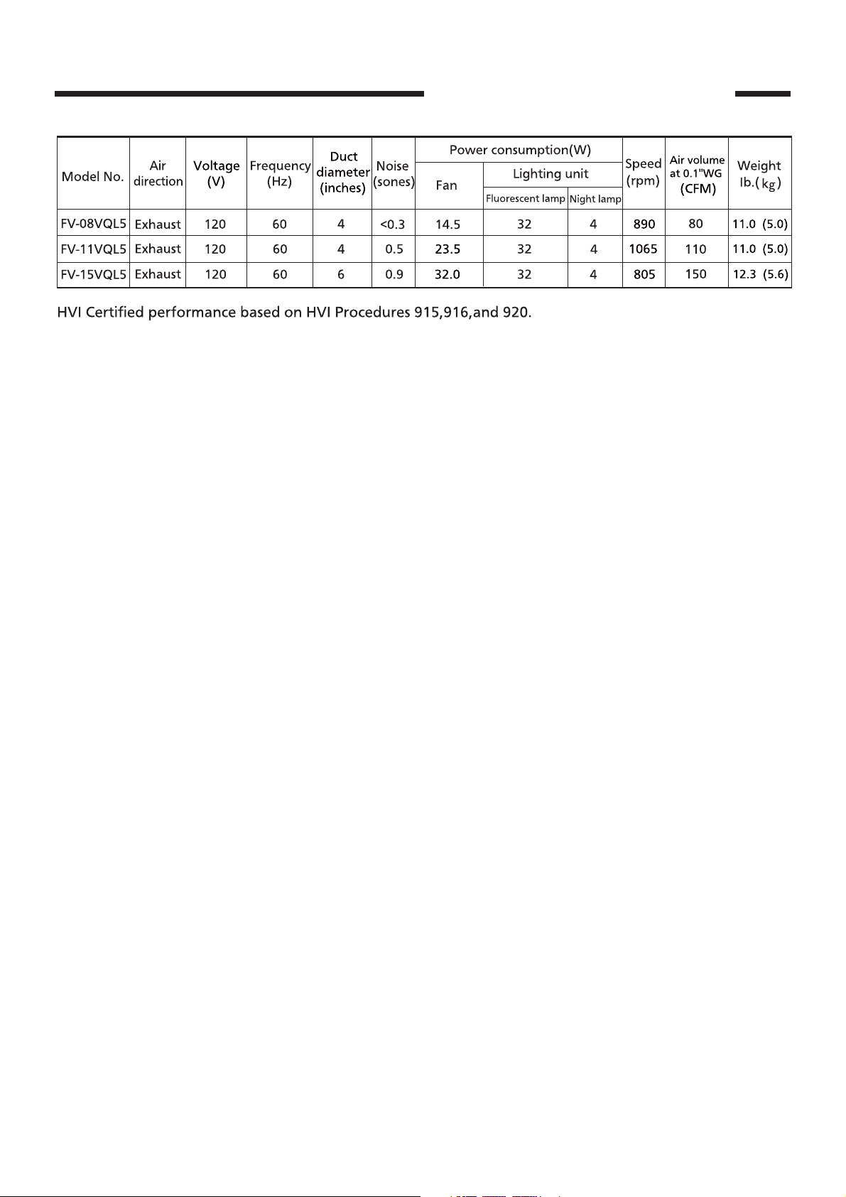
1.Specifications
FV-08VQL5 FV-11VQL5
FV-15VQL5
1
Page 3
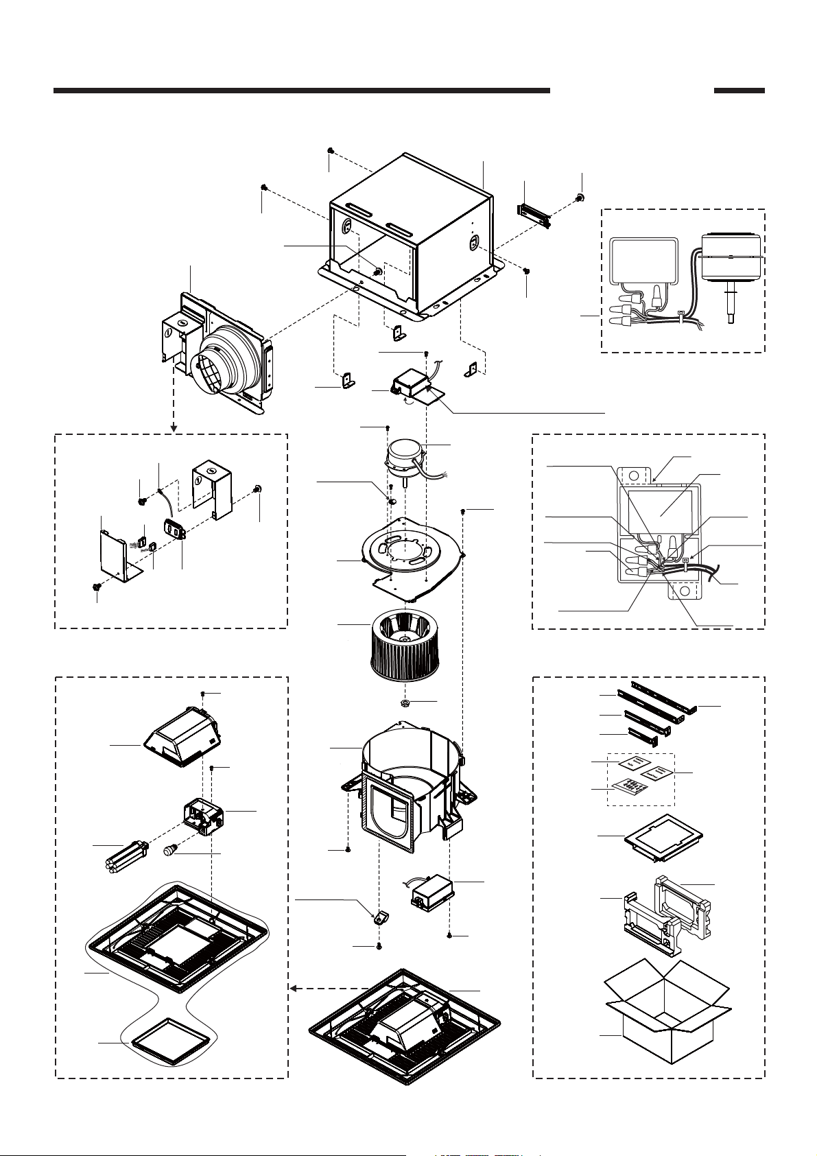
2.Parts Identification
FV-08VQL5
FV-11VQL5
4
8
D
9
7
5
6
B
Details Of Wiring Section
1
A
2
B
(2pcs)
A
A
A
35
C
(2pcs)
3
(3pcs)
10
C
(4pcs)
Cord Clip
B
12
Capacitor Box
11
C
(6pcs)
Section
(Motor Lead)
(Motor Lead)
(Motor Lead)
Red
White
White
24
(4pcs)
Black
(Motor Lead)
13
Motor Unit
(10)
23
White
(Cord)
Binder Tie
25
Black
(Cord)
Capacitor Box Section
19
21
22
17
Grille Unit
E
20
14
27
36
26
37
15
C
29
28
30
18
31
A
(3pcs)
Cord Clip
(3pcs)
16
32
33
C
C
(3pcs)
38
34
Main Packing Materials
2
Page 4
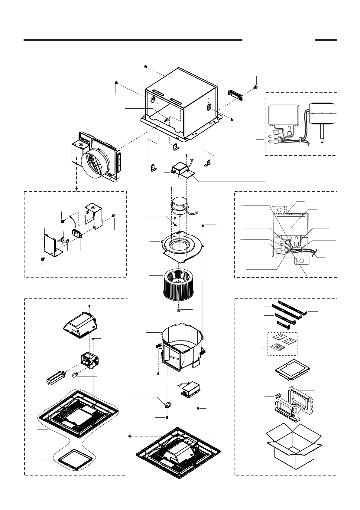
2.Parts Identification
FV-15VQL5
4
8
D
9
7
5
6
B
Details Of Wiring Section
1
A
2
B
(2pcs)
A
A
A
35
C
(2pcs)
3
(3pcs)
10
E
(3pcs)
Capacitor Box
Section
Red
(Motor Lead)
11
Cord Clip
White
C
B
(6pcs)
12
(Motor Lead)
White
(Motor Lead)
24
(4pcs)
Black
(Motor Lead)
13
Motor Unit
(10)
23
White
(Cord)
Binder Tie
25
Black
(Cord)
Capacitor Box Section
19
21
22
17
Grille Unit
F
20
14
27
36
26
37
C
15
29
28
30
18
A
(3pcs)
Cord Clip
(3pcs)
16
31
32
33
C
C
(3pcs)
38
34
Main Packing Materials
3
Page 5

2.Parts Identification
FV-08VQL5
FV-11VQL5
FV-15VQL5
Ballast Assembly Replacement Method
If the ballast assembly was damaged,please order the new grille unit section(FFV3420057S) to
replace defective ballast assembly& .Please refer to P14-P16 for replacement
guide.
Remark:The minimum quantity of an order for this new grille unit is 10 sets.
40 41
39
Panasonic
original grille unit
Replacement
Ballast Assembly
(16)
(2pcs)
(21)
42
44
(20)
(E)
( )
C
43
(22)
46
(2pcs)
45
47
(11pcs)
Total Packing Set:10sets
Grille Unit
Packing Method
4
Page 6

3.Wiring Diagram
FV-08VQL5 FV-11VQL5
FV-15VQL5
5
Page 7

No. Part No. Part Name Q'ty Remark
1 FFV1600111S Frame Assembly 1
2 FFV0420027S Bracket Cover 1
3 FFV0800001S Casing Support 3
4 FFV0000109S Adapter Assembly 1
Include One Bracket Cover&Two Screw
5 FFV0900047S Connector Plate 1
6 FFV0900038S Connector Assembly V 1
7 FFV0900039S Connector Assembly L 1
8 FFV3402103S Earth Lead Wire 1
9 FFV2800012S Junction Box Cover 1
10 FFV0760028S Capacitor Box 1
11 FFV3702217S Motor Assembly 1
(11) FFV3702215S Motor Assembly 1
12 FFV3730086S Motor Support 1
13 FFV0400103S Blade 1
14 FFV7020021S Nut 1 For Fixing Blade
15 FFV0790077S Casing 1
16 FFV3420057S Grille Unit Section 1 Include Packing Section
17 FFV3420025S Light Kit Cover Assembly 1
18 FFV3420026S Lamp Holder Section 1
19 FFV3420085S Fluorescent Lamp 1 Brand:Maxlite
20 FFV3420005S Night Lamp 1
21 FFV3420028S Grille Section 1 Include Lamp Cover
22 FFV3420029S Lamp Cover 1
23 FFV0750203S Capacitor 1 AC250V 1.1uF,For FV-08VQL5
(23) FFV0750204S Capacitor 1 AC250V 1.7uF,For FV-11VQL5
24 FFV0900024S Connector 4
25 FFV0730031S Cord 1
26 FFV5710023S
Suspension Bracket Ⅰ 2
27 FFV5710024S Suspension Bracket Ⅱ 2
28 FFV2540107S Installation Instruction 1 For USA Market
(28) FFV2540108S Installation Instruction 1 For CA Market
29 FFV2540109S Instruction 1
30 FFV0010200S Accessory A 1
31 FFV4710343S Grille Case Assembly 1
32 FFV4710344S Right Pad 1
33 FFV4710345S Left Pad 1
34 FFV9000955S Packing Case Assembly 1 For FV-08VQL5
(34) FFV9000956S Packing Case Assembly 1 For FV-11VQL5
35 FFV3702221S Motor Unit 1 For FV-08VQL5
(35) FFV3702220S Motor Unit 1 For-FV-11VQL5
4.Parts List
FV-08VQL5
FV-11VQL5
6
Page 8

No. Part No. Part Name Q'ty Remark
36 FFV5710018S
Suspension Bracket Ⅳ 1
37 FFV5710019S Suspension Bracket Ⅲ 1
38 FFV3420086S Grille Unit 1 Fluorescent Lamp Brand:Maxlite
39 FFV2540164S Installation Instruction 1
40 FFV0010230S Accessory A 1
41 FFV0730032S Cord Assembly B 1
42 FFV3420066S Light Kit Cover Assembly 1
43 FFV3420071S Lamp Holder Section 1
44 FFV3420067S Fluorescent Lamp 2
45 FFV9001068S Packing Case 1
46 FFV4710361S Pad A 2
47 FFV4710362S Pad B 11
A FFV7000065S Bind Screw 8
B FFV7000108S Truss Tap Screw 4
C FFV7000089S Truss Tap Screw 17
D FFV7000168S Screw Assembly 1 Include Spring Washer&P.R Washer
E FFV7000191S Bind Screw 1 For Fixing Light Cover
4.Parts List
FV-08VQL5
FV-11VQL5
7
Page 9

No. Part No. Part Name Q'ty Remark
1 FFV1600111S Frame Assembly 1
2 FFV0420027S Bracket Cover 1
3 FFV0800001S Casing Support 3
4 FFV0000110S Adapter Assembly 1
Include One Bracket Cover&Two Screw
5 FFV0900047S Connector Plate 1
6 FFV0900038S Connector Assembly V 1
7 FFV0900039S Connector Assembly L 1
8 FFV3402103S Earth Lead Wire 1
9 FFV2800012S Junction Box Cover 1
10 FFV0760028S Capacitor Box 1
11 FFV3702216S Motor Assembly 1
12 FFV3730087S Motor Support 1
13 FFV0400104S Blade 1
14 FFV7020021S Nut 1 For Fixing Blade
15 FFV0790078S Casing 1
16 FFV3420057S Grille Unit Section 1 Include Packing Section
17 FFV3420025S Light Kit Cover Assembly 1
18 FFV3420026S Lamp Holder Section 1
19 FFV3420085S Fluorescent Lamp 1 Brand:Maxlite
20 FFV3420005S Night Lamp 1
21 FFV3420028S Grille Section 1 Include Lamp Cover
22 FFV3420029S Lamp Cover 1
23 FFV0750129S Capacitor 1 AC250V 3.5uF
24 FFV0900024S Connector 4
25 FFV0730031S Cord 1
26 FFV5710023S
Suspension Bracket Ⅰ 2
27 FFV5710024S Suspension Bracket Ⅱ 2
28 FFV2540107S Installation Instruction 1 For USA Market
(28) FFV2540108S Installation Instruction 1 For CA Market
29 FFV2540109S Instruction 1
30 FFV0010200S Accessory A 1
31 FFV4710343S Grille Case Assembly 1
32 FFV4710344S Right Pad 1
33 FFV4710345S Left Pad 1
34 FFV9000957S Packing Case Assembly 1
35 FFV3702234S Motor Unit 1
4.Parts List
FV-15VQL5
8
Page 10

No. Part No. Part Name Q'ty Remark
36 FFV5710018S
Suspension Bracket Ⅳ 1
37 FFV5710019S Suspension Bracket Ⅲ 1
38 FFV3420086S Grille Unit 1 Fluorescent Lamp Brand:Maxlite
39 FFV2540164S Installation Instruction 1
40 FFV0010230S Accessory A 1
41 FFV0730032S Cord Assembly B 1
42 FFV3420066S Light Kit Cover Assembly 1
43 FFV3420071S Lamp Holder Section 1
44 FFV3420067S Fluorescent Lamp 2
45 FFV9001068S Packing Case 1
46 FFV4710361S Pad A 2
47 FFV4710362S Pad B 11
A FFV7000065S Bind Screw 8
B FFV7000108S Truss Tap Screw 4
C FFV7000089S Truss Tap Screw 13
D FFV7000168S Screw Assembly 1 Include Spring Washer&P.R Washer
E FFV7000079S Pan Tap Screw 3 For Fixing Motor Assembly
F FFV7000191S Bind Screw 1 For Fixing Light Cover
4.Parts List
FV-15VQL5
9
Page 11

5.Replacement Guide
INSTALLATION
WARNING
Disconnect power source before working
on unit.
1. Remove the primary light kit grille by pulling down
one mounting spring and remove plug connector ,
then pull down the other mounting spring (Squeeze
mounting spring and pull down carefully) (Fig.1)
2. Take off the ballast assembly by removing 3 screws
(ST4.2X12). (Fig.2)
Ⅰ
.
CAUTION
Keep the screws that are removed for
following use.
3. Take out the light lead wire assembly A from
accessories, and connect to junction box. Then
fix the light lead wire assembly by 3 screws (ST4.2X12),
and 3 cord clips(5N,from accessories).(Fig.3)
Remove the tapes from grille and springs
before installation new light kit grille as below
Plug connector
Claw
Rib
Ceiling
Gloves
Lighting unit
3 screws(ST4.2X12)
Mounting spring
Grille
Fig.1
Ballast Assembly
Switch box
Fig.2
Tapes
4.Take out the new light kit grille.Remove screw(M4X8).
Remove light kit cover assembly. (Fig.4)
5. Install the night lamp and fluorescent lamps.
(Fig.5)
Only fix the sensor lead wire.
Light lead wire assembly A
3 screws(ST4.2X12),3 cord clips(5N)
Remove screw
Light kit cover
assembly
Fluorescent
lamp
(M4X8)
Fig.3
Fig.4
3
Night lamp
Fig.5
10
Page 12

5.Replacement Guide
INSTALLATION
6. Install light kit cover assembly. (Fig.6)
7. Insert the grille mounting spring on the wiring
side into the slot and insert the plug connector
into the housing of the lighting unit.(Fig.7)
CAUTION
Before turn on the light, make sure the
connector at the correct position. If not, the
lighting can’t work.
The claw of connector must latch the rib
completely. (Fig.7)
8. Insert the other mounting spring into the slot as
shown and mount grille to fan body. (Fig.8)
CAUTION
Mount grille carefully so that lead wire of
lighting unit is not pinched.
Plug connector
lighting unit
Rib
Claw
Ceiling
Ceiling
Gloves
Light kit cover
assembly
Grille
Insert
Plug connector
Secure screw
(M4X8)
Mounting spring
lighting unit
Mounting spring
Fig.6
Fig.7
Grille
Gloves
Fig.8
11
Page 13

5.Replacement Guide
MAINTENANCE(REPLACEMENT OF LAMP)
lighting unit
Rib
Claw
Light kit cover
assembly
Plug connector
WARNING
Disconnect power source before working
on unit.
This is a pin type lamp base and the lamp’s
glass is fragile.To remove,pull out carefully.
4W night lamp has threaded base,Remove
by turning counterclockwise.
Make sure the temperature of lens and lighting
unit has cooled down before maintenance
(cleaning) or replacement of lamp.
CAUTION
Remove dust and dirt from light kit cover
assembly and lens, before replace the lamps.
1. Remove grille by pulling down one mounting spring. Then
pull down the other mounting spring. (Squeeze mounting
spring and pull down carefully) (Fig.1)
Ceiling
Gloves
Insert
Fluorescent
lamp
Plug connector
Remove screw
(M4X8)
Lens
Grille
Fig.1
Fig.2
2. Remove the screw as shown in step 1 of (Fig.2)
Remove the light kit cover assembly as shown in step 2 of (Fig.2)
3. Remove the fluorescent lamps (Maxlite MLS13GU35,13W)
and night lamp as shown in step 1 ,step 2 and step 3 of (Fig.3)
4. Install new night lamp (MAX 4W incandescent lamp) and
new fluorescent lamps (Maxlite MLS13GU35,13W) as
shown in step 1 ,step 2 and step 3 of (Fig.4)
5.Install light kit cover assembly.(Fig.5)
Fluorescent
lamp
3
3
Light kit cover
assembly
Night lamp
Night lamp
Fig.3
Fig.4
Secure screw
(M4X8)
Fig.5
12
 Loading...