

Page 1
PEG1311050CE
Version:1402
Service Manual
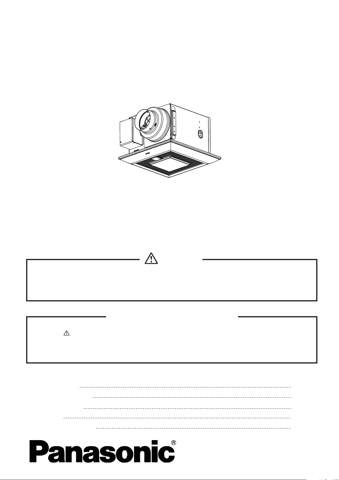
Ventilating Fan
WhisperSense
(North America Market)
TM
FV-08VQCL5
FV-11VQCL5
WARNING
This service information is designed for experienced rep ai r te ch ni ci an s on ly a nd i s no t de si gn ed for use by
the general public. It does not contain warnings or cautions to ad vi se n on -t ec hn ic al i nd iv id ua ls of potential
dangers in attempting to service a product. Products powered by el ec tr ic it y sh ou ld b e se rv ic ed o r re pa ir ed
only by experienced professional technicians. Any a tt em pt t o se rv ic e or r ep ai r th e pr od uc t or p ro du ct s de alt
with in this service information by anyone else could result in se ri ou s in ju ry o r de at h.
IMPORTANT SAFETY NOTICE
There are special components used in this equipment which ar e im po rt an t fo r sa fe ty. These parts are
marked by in the Schematic Diagrams, Exploded Views and Replacement Parts List. It is essential
that these critical parts should be replaced with manufacturer 's s pe ci fi ed p ar ts t o pr ev en t sh oc k, f ir e
or other hazards. Do not modify the original design without pe rm is si on o f ma nu fa ct ur e.
We suggest to handle such parts after the static electricity prevention.
It is forbidden to touch the PCB parts by bare hands during the repairin g pr oc es s.
CONTENTS
1.Specifications
2.Parts Identification
3.Wiring Diagram
4.Parts List
5.Replacement Guide
PAGE
1
2~4
5
6~7
8~10
Page 2
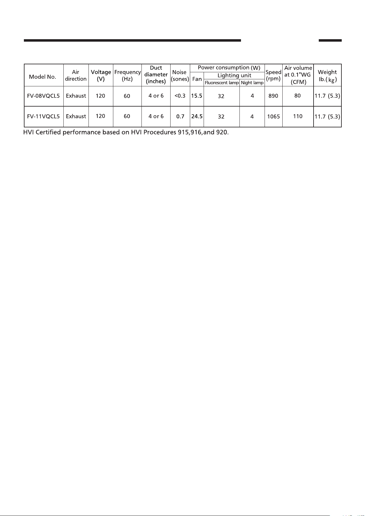
1.Specifications
FV-08VQCL5
FV-11VQCL5
1
Page 3
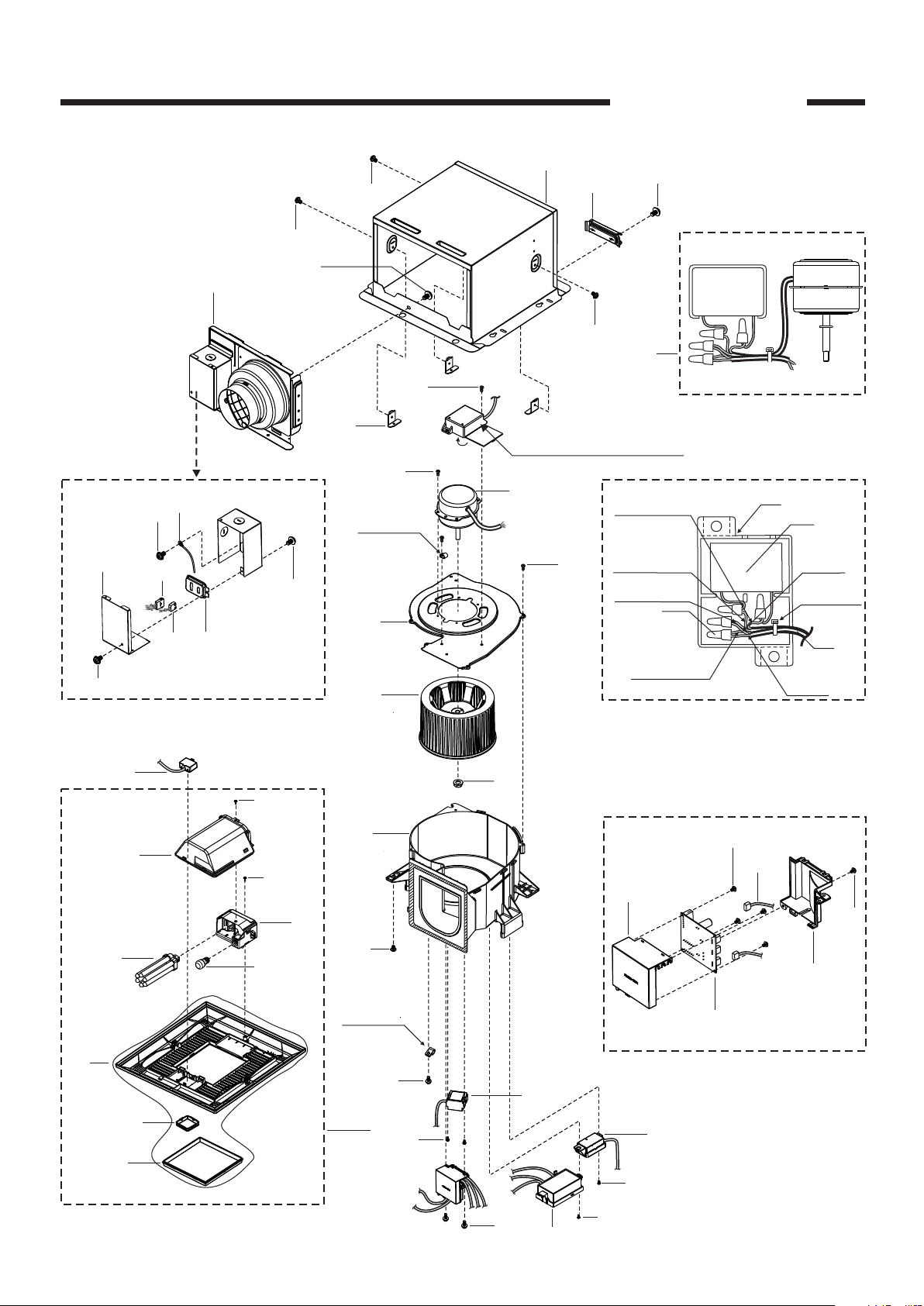
2.Parts Identification
FV-08VQCL5
FV-11VQCL5
4
7
D
8
15
5
6
B
Details Of Wiring Section
1
A
2
B
(2pcs)
A
B
A
32
C
(2pcs)
3
(3pcs)
C
(4pcs)
Cord Clip
B
11
Capacitor Box
Section
10
C
(6pcs)
Red
(Motor Lead)
White
(Moto r Lead)
White
(Moto r Lead)
34
(4pcs)
Black
(Moto r Lead)
12
Motor Unit
9
33
White
(Cord)
Binder Tie
35
Black
(Cord)
Capacitor Box Section
25
22
27
24
20
26
Grille Unit
G
23
13
14
C
H
(4pcs)
30
28
21
A
(3pcs)
Cord Clip
(3pcs)
29
C
31
Main PCB Section
C
(3pcs)
19
E
(2pcs)
16
17
C
C
(2pcs)
18
F
2
Page 4
2.Parts Identification
FV-08VQCL5
FV-11VQCL5
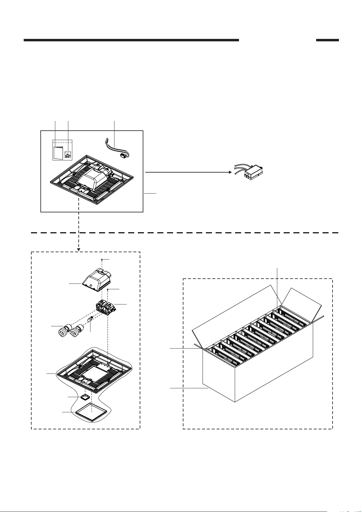
Ballast Assembly Replacement Method
If the ballast assembly was damaged,please order the new grille unit section(FFV3420058S) to
replace defective ballast assembly&original grille unit.Please refer to P12-P14 for replacement
guide.
Remark:The minimum quantity of an order for this new grille unit is 10 sets.
57 58
56
Pa
n
as
on
ic
Replacement
Ballast Assembly
(18)
(2pcs)
(25)
61
(26)
(27)
59
(23)
(G)
( )
C
60
63
(2pcs)
62
64
(11pcs)
Total Packing Set:10sets
Grille Unit
Packing Method
3
Page 5

2.Parts Identification
36
(36)
37
38
48
50
FV-08VQCL5
FV-11VQCL5
45
46
47
51
44
49
39
40
C
LIST EN
A3756 82G8
FAN
8B68
US
41
m
In
m
ch
1
_
2
2
60
2
50
40
1
_
1
2
30
1
20
1
_
2
10
43
Main Labels
(Stuck On Frame Assy)
52
53
54
42
55
Main Packing Materials
4
Page 6

3.Wiring Diagram
FV-08VQCL5
FV-11VQCL5
5
Page 7

No. Part No. Part Name Q'ty Remark
1
FFV1600111S Frame Assembly 1
2 FFV0420027S Bracket Cover 1
3 FFV0800001S Casing Support 3
4 FFV0000121S Adapter Assembly 1
5 FFV0900048S Connector Plate 1
6 FFV0900049S Connector Assembly V 1
7 FFV3402103S Earth Lead Wire Assembly 1
8 FFV2800012S Junction Cover 1
9 FFV0760028S Capacitor Box 1
10 FFV3702217S Motor Assembly 1 For FV-08VQCL5
(10) FFV 3702215S Motor Assembly 1 For F V -11VQCL5
11 FFV3730086S Motor Support 1
12 FFV0400103S Blade 1
13 FFV7020021S Nut 1
14 FFV0790077S Casing 1
15 FFV0900039S Connector Assembly L 1
16 FFV2220053S Humid Sensor Assembly 1
17 FFV5530065S Switch Assembly 1
18 FFV3420058S Grille Unit Section 1 Include Packing Section
19 FFV3420087S Grille Unit 1 Fluorescent Lamp Brand:Maxlite
20 FFV3420025S Light Kit Cover Assembly 1
21 FFV3420026S Lamp Holder Section 1
22 FFV3420085S Fluorescent Lamp 1 Brand:Maxlite
23 FFV3420005S Night Lamp 1
24 FFV5500028S Sensor Box Assembly 1
25 FFV3420030S Grille Section 1 Include Sensor C over&Lamp Cover
26 FFV2220051S Sensor Cover 1
27 FFV3420029S Lamp Cover 1
28 FFV3740021S Main PCB Box 1
29 FFV3740022S Main PCB 1
30 FFV4620077S Power Lead Wire 1
31 FFV3740023S Main PCB Cover 1
32 FFV3702243S Motor Unit 1 For F V-08VQCL5
(32) FFV 3702244S Motor Unit 1 For FV-11VQCL5
33 FFV0750203S Capacitor 1 For FV-08VQCL5
(33) FFV 0750204S Capaci tor 1 For FV -11VQCL5
34 FFV0900024S Connector 4
35 FFV3700330S Motor Lead Wire 1
36 FFV4020687S Name Plate 1 For FV-08VQCL5
4.Parts List
FV-08VQCL5
FV-11VQCL5
6
Page 8

4.Parts List
No. Part No. Part Name Q'ty Remark
(36) FFV4020688S Name Plate 1 For FV-11VQCL5
37 FFV1320001S ESP Mark 1
38 FFV0810010S Warning Label 1
39 FFV2260003S UL Mark 1
40 FFV2260002S HVI Mark 1
41 FFV6730045S Warning Label 1
42 FFV5720015S Scale Tape 1
43 FFV6730051S Wiring Label 1
44 FFV5710023S
Suspension Bracket Ⅰ
1
45 FFV5710024S
Suspension Bracket Ⅱ
1
46 FFV5710018S
Suspension Bracket Ⅳ
1
47 FFV5710019S
Suspension Bracket Ⅲ
1
48 FFV2540123S Installation Instruction 1 English,For CA Market/USA Market
49 FFV2540124S Installation Instruction 1 French,For USA Market
(49) FFV2540125S Installation Instruction 1 Spanish,For CA Market
50 FFV0010200S Accessory A 1
51 FFV4710210S Grille Case Assembly 1
52 FFV4710344S Right Pad 1
53 FFV4710345S Left Pad 1
54 FFV4710330S Sensor Pad 1
55 FFV9000985S Packing Case Assembly 1 For FV-08VQCL5
(55) FFV9000986S Packing Case Assembly 1 For FV-11VQCL5
56 FFV2540164S Installation Instruction 1
57 FFV0010230S Accessory A 1
58 FFV0730032S Cord Assembly B 1
59 FFV3420066S Light Kit Cover Assembly 1
60 FFV3420071S Lamp Holder Section 1
61 FFV3420067S Fluorescent Lamp 2
62 FFV9001067S Packing Case 1
63 FFV4710361S Pad A 2
64 FFV4710362S Pad B 11
A FFV7000065S Bind Screw 6
B FFV7000108S Truss Tap Screw 5
C FFV7000089S Truss Tap Screw 20
D FFV7000168S Screw Assembly 1 Include Spring Washer&P.R Washer
E FFV7000195S Pan Tap Screw 2
F FFV7000074S Truss Tap Screw 1
G FFV7000191S Bind Screw 1 For Fixing Light Kit Cover Assembly
H FFV7000145S Truss Tap Screw 4
FV-08VQCL5
FV-11VQCL5
7
Page 9

5.Replacement Guide
INSTALLATION
WARNING
Disconnect power source before working
on unit.
1. Remove th e primary light k it gr ille by pulling d own
one mounti ng spring, and remove
plug conne ctorⅠ,then pull d own t he other mounti ng
spring (Sq ueeze mountin g spr ing and pull down
carefull y) ( Fig.1)
2. Take o ff the bal last assembly b y rem oving 3 screws
(ST4.2X1 2). ( Fig.2)
.
remove sen sor unit
CAUTION
Keep the screws that are removed for
following use.
3. Fix the swi tch b ox by 1 screw (ST4. 2X8) from
accessor ies. (Fig.3)
4. Take o ut th e light lead wire a ssembly A from
accessor ies, and connec t to ju nction box. Then
fix the ligh t lea d wire assembly b y 3 screws (ST4.2 X12),
and 3 cord cli ps(5N,from acces sories).(Fi g.4)
IMPORTANT:
Remove the tapes from grille and springs
before installation new light kit grille as below
Plug connector
Claw
Rib
Ceiling
Gloves
Lighting unit
3 screw s(ST4.2X12)
Mounting spring
sensor unit
Grille
Fig.1
Ballast Assembly
Switch box
Fig.2
Switch box
Tapes
5.Take out the new light kit grille.Remove screw(M4X8).
Remove light kit cover assembly. (Fig.5)
Screw(ST4. 2X8)
For mode ls of F V-08 VKML3,
FV-1 3VK ML3 o nly. On ly fi x
the sens or le ad wi re.
Light l ead wire assembly A
3 screws (ST 4.2 X12),3 cord clips (5N )
Light k it co ver
assem bly
Remov e scr ew
(M4X8 )
Fig.3
Fig.4
Fig.5
8
Page 10

5.Replacement Guide
INSTALLATION
6. Install the night lamp and fluorescent lamps.
(Fig.6)
7. Install light kit cover assembly. (Fig.7)
8. Insert th e gri lle mounting sp ring on the wirin g
side into th e slot and insert the pl ug connector
into the hou sing of the lighting u nit.(Fig.8)
CAUTION
Before turn on the light, make sure the
connector at the correct position. If not, the
lighting can’t work.
The claw of connector must latch the rib
completely. (Fig.8)
9. Insert the sensor unit into slot of the grille
(position ① . Fix the sensor lead wire into the
clasp (position ② (Fig.9)
10. Insert t he ot her mounting sp ring into the slo t as
shown and mo unt grille to fan body. (Fig.10 )
)
).
Fluor esc ent
lamp
3
Plug connector
Ceiling
Gloves
Night l amp
Light k it co ver
assem bly
Fig.6
Secure screw
(M4X8)
Fig.7
Mounting spring
CAUTION
Mount grille carefully so that lead wire of
sensor unit and lighting unit is not pinched.
lighting unit
Rib
Claw
Ceiling
Grille
Grille
Insert
Plug connector
Sensor unit
Clasp
Grille
Mounting spring
lighting unit
Fig.8
Fig.9
Gloves
Fig.10
9
Page 11

5.Replacement Guide
MAINTENANCE(REPLACEMENT OF LAMP)
WARNING
Disconnect power source before working
on unit.
This is a pin type lamp base and the lamp’s
glass is fragile.To remove,pull out carefully.
4W night lamp has threaded base,Remove
by turn ing counterclockwise.
Make sure the temperature of lens and lighting
unit has cooled down before maintenance
(cleaning) or replacement of lamp.
Plug connector
lighting unit
Rib
Claw
Lig ht kit co ver
ass embly
CAUTION
Remove dust and dirt from light kit cover
assembly and lens, before replace the lamps.
1. Remove gr ille by pulling d own o ne mounting spr ing. The n
pull down th e other mountin g spr ing. (Squeeze m ounting
spring and p ull down carefu lly ) (Fig.1)
Ceiling
Gloves
Insert
Flu oresc ent
lam p
Plug connector
Rem ove scr ew
(M4 X8)
Lens
Grille
Fig.1
Fig.2
2. Remove the screw as shown in step 1 of (Fig.2)
Remov e the light kit cover assembly as shown in step 2 of (Fig.2)
3. Remove the fluorescent lamps (Maxlite MLS13GU35,13W)
and night lamp as shown in step 1 ,step 2 and step 3 of (Fig.3)
4. Install new night lamp (MAX 4W incandescent lamp) and
new fluorescent lamps (Maxlite MLS13GU35,13W) as
shown in step 1 ,step 2 and step 3 of (Fig.4)
5.Install light kit cover assembly.(Fig.5)
Fluor esc ent
lamp
3
3
Night l amp
Light k it co ver
assem bly
Nig ht lamp
Secure screw
(M4X8)
Fig.3
Fig.4
Fig.5
10
 Loading...