

Page 1
FV-08VQC5 FV-11VQC5
6 8
Centered/
9
11
11
11
Page 2
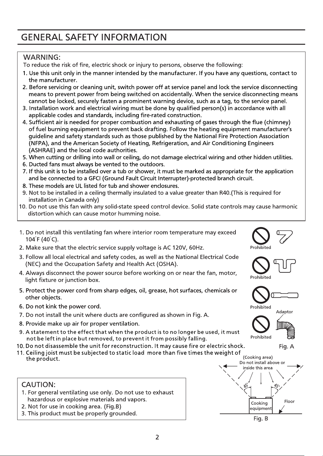
12. Do not install with a method which is not approved in the instructions.
Page 3
These Panasonic ventilating fan models are equipped with a motion sensor and a humidity
sensor that turn on automatically when motion is detected, when humidity increases rapidly,
or when humidity rises above a 30% 80% relative humidity set-point. It is user-adjustable to
operate 0.5 60 minutes after the sensors are no longer detected.
~
~
s
a
Page 4
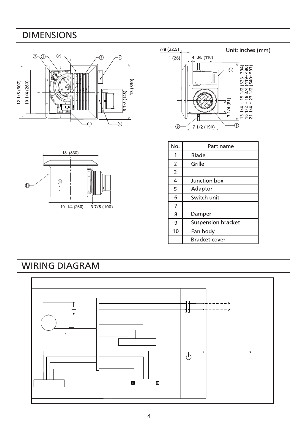
3 7/8(98)
Motion sensor unit
Humidity sensor unit
11
Fan body
Main control circuit
Red
White
White
Motor
Black
(114 C Fuse in Motor)
lmpedance-protected
Motion sensor
Capacitor
Black
Green
White
Red
White
Black
Yellow
Red
White
Humidity sensor
Black
Yellow
Red
White
Humidity setting
Adjustment
switch
Timer
Junction box
White
Black
Green
Neutral
( )
Live
VENT.
(Power supply)
(Earth ground)
AC120V
60Hz
Page 5

MAX
~80%
MIN
~30%
Humidity preset switch positions (Tolerance:±10%)
Humidity
preset switch
Timer
preset switch
MAX
~80%
MIN
~30%
MIN MAX
Factory setting: 50% RH (" " means "about")
Timer preset switch positions
30%
~~ ~ ~ ~ ~ ~
40%
~ ~
50% 60% 70% 80%
Timer
Position : refer to 0.5 minute
Panasonic ventilating fan
responds to:
(1) Motion sensor detectible
condition.
(2) Humidity sensor detectible
condition.
Motion sensor detectible
condition
The delay time is determined
by timer preset switch.
The unit continues running for
Human
activity
an adjustable duration
of 0.5 to 60 minutes, after
Fan activity
motion is no longer detected.
Stop
Room temperature is
25 (77 F).
Remains running
until the delay time
has passed
Humidity sensor detectible condition
(a) rapid to moderate humidity increases and (b) humidity above a 30% 80% relative humidity
~
set-point. (a) and (b) are set with "HUMIDITY SETTING" adjustment. Fan may occasionally turn
on when environmental conditions change. The "TIMER" controls how long the fan remains on
(a) after rise in humidity and (b) humidity level is below the set-point decreasing about 5%RH.
1. If this unit is to be install over a tub or shower, for best results, locate it near the shower
head.
2. Long-time operation will influence the detecting precision as dust accumulates. Humidity
preset switch may need to be adjusted.
Page 6

Motion sensor
unit
6
Page 7

4. Install a circular duct and secure it with clamps,
or wire ties and seal it with mastic or masitc tape.
A 4 or 6 inch circular duct is needed to connect to
the relevant part of adaptor. (Fig.3)
Mastic tape
Motion sensor
unit
page 4
7
Page 8

fix
(
3
po
s
it
ion
)
(
Fi
g.6).
9. Adjust timer preset switch and humidity preset
switch (Fig.7). Refer to switch indication on page 5.
8
Page 9

CENTERED/
Motion sensor
unit
9
Page 10

4. Do not use cleaning sprays, solvents, or water on
or near the sensors.
Remove grille by pulling down the mounting spring
opposite the sensor lead.
10
Page 11

The ducting from this fan to the outside of the building has a strong effect on the air flow, noise
and energy use of the fan. Use the shortest, straightest duct routing possible for best performance,
and avoid installing the fan with smaller ducts than recommended. Insulation around the ducts can
reduce energy loss and inhibit mold growth. Fans installed with existing ducts may not achieve their
rated air flow.
FV-08VQC5
FV-11VQC5
15.5
23.0
815
960
1-866-292-7299(USA)
110
11
Page 12

Two Riverfront Plaza, Newark, NJ 07102
Panasoic Corporation 2011-2015
T0511-2095 08VQC5420B
 Loading...