

Panasonic FP? Positioning Unit RTEX, FP2 Positioning Unit RTEX Technical Manual

Safety Precautions
Observe the following notices to ensure personal safety or to prevent accidents.
To ensure that you use this product correctly, read this User’s Manual thoroughly before use.
Make sure that you fully understand the product and information on safety.
This manual uses two safety flags to indicate different levels of danger.
WARNING
If critical situations that could lead to user’s death or serious injury is assumed by
mishandling of the product.
-Always take precautions to ensure the overall safety of your system, so that the whole
system remains safe in the event of failure of this product or other external factor.
-Do not use this product in areas with inflammable gas. It could lead to an explosion.
-Exposing this product to excessive heat or open flames could cause damage to the lithium
battery or other electronic parts.
CAUTION
If critical situations that could lead to user’s injury or only property damage is
assumed by mishandling of the product.
-To prevent excessive exothermic heat or smoke generation, use this product at the values
less than the maximum of the characteristics and performance that are assured in these
specifications.
-Do not dismantle or remodel the product. It could cause excessive exothermic heat or smoke
generation.
-Do not touch the terminal while turning on electricity. It could lead to an electric shock.
-Use the external devices to function the emergency stop and interlock circuit.
-Connect the wires or connectors securely.
The loose connection could cause excessive exothermic heat or smoke generat ion.
-Do not allow foreign matters such as liquid, flammable materials, metals to go into the inside
of the product. It could cause excessive exothermic heat or smoke generation.
-Do not undertake construction (such as connection and disconnection) while the power
supply is on. It could lead to an electric shock.
Copyright / Trademarks
-This manual and its contents are copyrighted.
-You may not copy this manual, in whole or part, without written consent of
Industrial Devices SUNX Co., Ltd.
-Windows is a registered trademark of Microsoft Corporation in th e United States and other
countries.
-All other company names and product names are trademarks or registered trademarks of
their respective owners.
Panasonic
PLC_ORG

Table of Contents
Difference of Functions Between Versions
Glossary
About Illustrations in This Manual
1. Functions of Unit and Restrictions on Combination .......... 1-1
1.1 Functions of Positioning Unit RTEX ......................................................... 1-2
1.2 Restrictions on Units Combination ........................................................... 1-4
1.3 Restrictions on Unit and AMP .................................................................. 1-4
2. Parts and Functions ............................................................. 2-1
2.1 Parts and Functions ................................................................................. 2-2
2.2 Operation Status Display LEDs ................................................................ 2-3
3. Wiring .................................................................................... 3-1
3.1 Wiring of Network ..................................................................................... 3-2
3.2 Network Connector .................................................................................. 3-3
3.3 Wiring of Pulser Input Connector ............................................................. 3-4
4. Power On/Off and Items to Check ....................................... 4-1
4.1 Safety Circuit Design ............................................................................... 4-2
4.2 Before Turning On the Power ................................................................... 4-3
4.3 Procedure for Turning On the Power ........................................................ 4-4
5. Preparation For Operation ................................................... 5-1
5.1 Procedures For System Establishment .................................................... 5-2
5.2 Preparation For Operation ....................................................................... 5-8
6. I/O Allocation ........................................................................ 6-1
6.1 Occupied I/O Area ................................................................................... 6-2
6.2 Allocation of Each Contact ....................................................................... 6-3
7. Setting Tool Configurator PM .............................................. 7-1
7.1 Connection With Computer ...................................................................... 7-2
7.2 Functions of Configurator PM ................................................................... 7-3
7.3 Installing Configurator PM ........................................................................ 7-5
7.4 Starting Configurator PM ........................................................................ 7-10
7.5 Treating Files ......................................................................................... 7-11
7.6 Exiting Configurator PM ......................................................................... 7-17
7.7 Connection to Positioning Unit ............................................................... 7-18
7.8 Parameter Settings ................................................................................ 7-20
7.9 Changing Axis Information ..................................................................... 7-23
7.10 Setting Positioning Data ....................................................................... 7-24
i

7.11 How to Edit Positioning Data ................................................................ 7-26
7.12 Customizing Software ........................................................................... 7-30
7.13 Checking Settings................................................................................. 7-32
7.14 Transferring Setting Data ...................................................................... 7-33
7.15 Data Monitor ......................................................................................... 7-37
7.16 Status Display ...................................................................................... 7-38
7.17 Tool Operation ...................................................................................... 7-39
8. Automatic Operation (Position Control) ............................. 8-1
8.1 Basic Operation ........................................................................................ 8-2
8.2 Interpolation Control ............................................................................... 8-15
8.3 Synchronous Operation .......................................................................... 8-28
8.4 Setting and Operation of Positioning Repeat Function ............................ 8-35
9. Manual Operation (JOG Operation) .................................... 9-1
9.1 Setting and Operation of Home Return ..................................................... 9-2
9.2 Changing the Speed During JOG Operation ............................................. 9-4
10. Manual Operation (Home Return) ................................... 10-1
10.1 Type of Home Return Method .............................................................. 10-2
10.2 AMP Settings and Usable Home Return Methods ................................ 10-6
10.3 Setting and Operation of Home Return ................................................. 10-7
11. Manual Operation (Pulser Operation) ............................. 11-1
11.1 Setting and Operation of Pulser Operation ........................................... 11-2
12. Stop Functions ................................................................. 12-1
12.1 Settings and Operations of Stop Functions ........................................... 12-2
12.2 Setting and Operation of Pause Function ............................................. 12-3
13. Supplementary Functions ............................................... 13-1
13.1 Dwell Time............................................................................................ 13-2
13.2 Software Limit ....................................................................................... 13-3
13.3 Torque Limit ......................................................................................... 13-4
13.4 Auxiliary Output Code and Auxiliary Output Contact ............................. 13-6
13.5 Actual Speed/Torque Value Judgment ................................................. 13-7
13.6 Imposition Flag and Completion Width ................................................. 13-8
13.7 Current Value Update ........................................................................... 13-9
13.8 Coordinate Origin ............................................................................... 13-11
13.9 Position Deviation Simple Monitor ...................................................... 13-12
13.10 AMP Parameter R/W Function .......................................................... 13-14
13.11 Position Deviation Simple Monitor .................................................... 13-20
14. Precautions During Programming .................................. 14-1
14.1 Precautions During Programming ......................................................... 14-2
ii

15. Errors and Warnings ........................................................ 15-1
15.1 Errors and Warnings ............................................................................ 15-2
15.2 List of Error Codes ............................................................................... 15-4
15.3 List of Warning Codes ........................................................................ 15-21
16. Troubleshooting ............................................................... 16-1
16.1 Cannot Communication With AMP ....................................................... 16-2
17. Specifications ................................................................... 17-1
17.1 Table of Specificationa ......................................................................... 17-2
17.2 Table of I/O Area .................................................................................. 17-6
17.3 Configuration of Shared Memory Areas ............................................. 17-12
17.4 Details of Common Area in Shared Memory ...................................... 17-13
17.5 Details of Each Axis Information Area in Shared Memory .................. 17-30
17.6 Details of Each Axis Setting Area in Shared Memory ......................... 17-40
18. Dimensions ....................................................................... 18-1
18.1 FPSigma Positioning Unit RTEX .......................................................... 18-2
18.2 FP2 Positioning Unit RTEX .................................................................. 18-3
19. Sample Programs ............................................................. 19-1
19.1 I/O Allocation of Sample Programs ...................................................... 19-2
19.2 Sample Programs ................................................................................ 19-4
iii

iv

Difference of Functions Between Versions
Version
Type
Added / modified functions
Positioning repeat function
Synchronous operation
J point (JOG positioning) control
Phase Z method / Data set method
Added "Delay mode" to Auxiliary contact
Position deviation simple monitor function
and Current update function.
Added error codes and warning code along with the addition of functions.
Changed the operations after the occurrence of errors.
functions
Supports MINAS A5N.
AMP parameter R/W function
functions
1.13
1.30
1.40
Additional
functions
Specification
change
Additional
Additional
Added Home return method
DOG method 2 / DOG method 3 / Limit method 1 / Limit method 2 /
Stop-on-contact method 1 / Stop-on-contact method 2 /
Eliminated Home offset function and added Coordinate origin function
Supports MINAS A6N.
v
Glossary
RTEX
RTEX, which stands for Realtime Express, is the network exclusive for motion connecting the Positioning
Unit RTEX and AMP.
* Realtime Express is the name of the network servo system produced by Panasonic.
AMP
AMP means a servo amplifier which controls a servo motor.
Configurator PM
Configurator PM is a setting tool for Positioning Unit RTEX. Using the Configurator PM enables the
settings for positioning data and various parameters, and various monitoring. As a tool operation mode
to activate a motor without using ladder programs is provided in this tool, it is convenient especially to
confirm the operation at the time of an initial start-up.
PANATERM
This is a setup support tool for the servo amplifiers of MINAS series made by Panasonic. By using this
tool, the parameter settings within the AMP, monitoring control statuses, the setup support or analysis of
machines can be executed on PC.
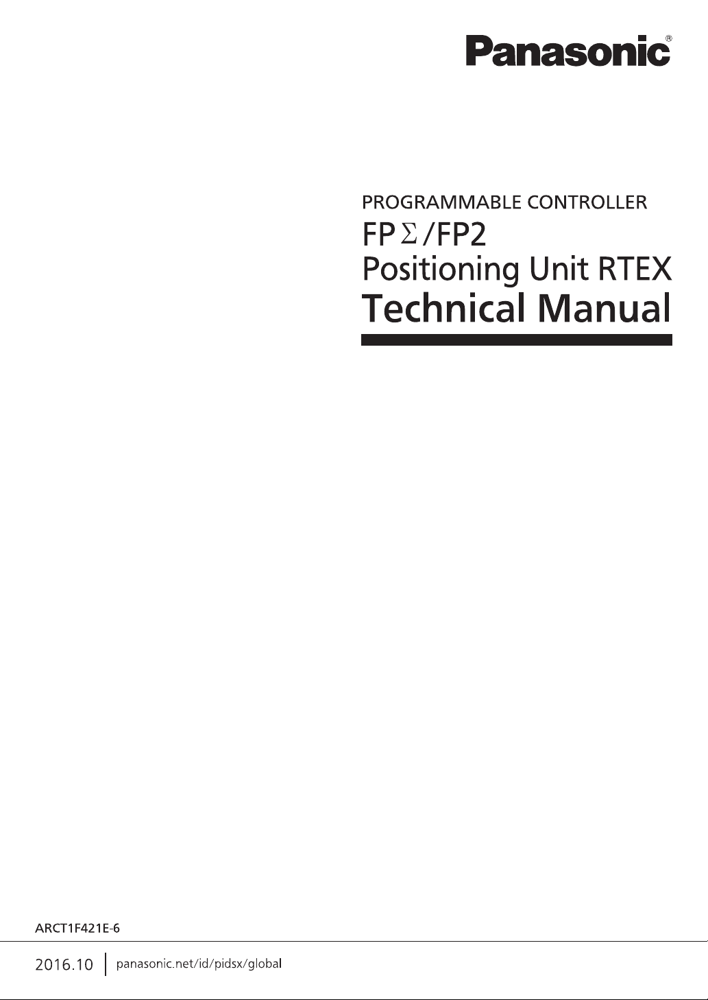
E point control
This is a method of control which is initiated up to an end point, and in this manual is referred to as “E
point control”. This method is used for a single - speed acceleration/deceleration. It is also called a
trapezoidal control.
P point control
This refers to control which passes through a “Pass Point”, and is called “P point control” in this manual.
This method is used when a multi-stage speed is to be specified in the same motion.
vi
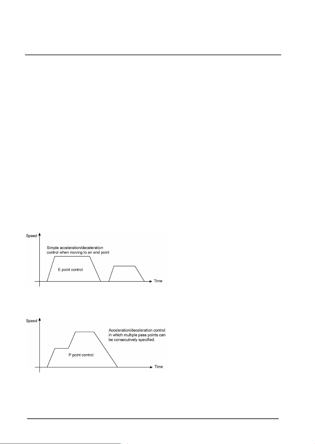
C point control
This refers to control which passes through a “Continuance Point”, and is called “C point control” in this
manual. This method is used for executing continuous E point controls by one-time start.
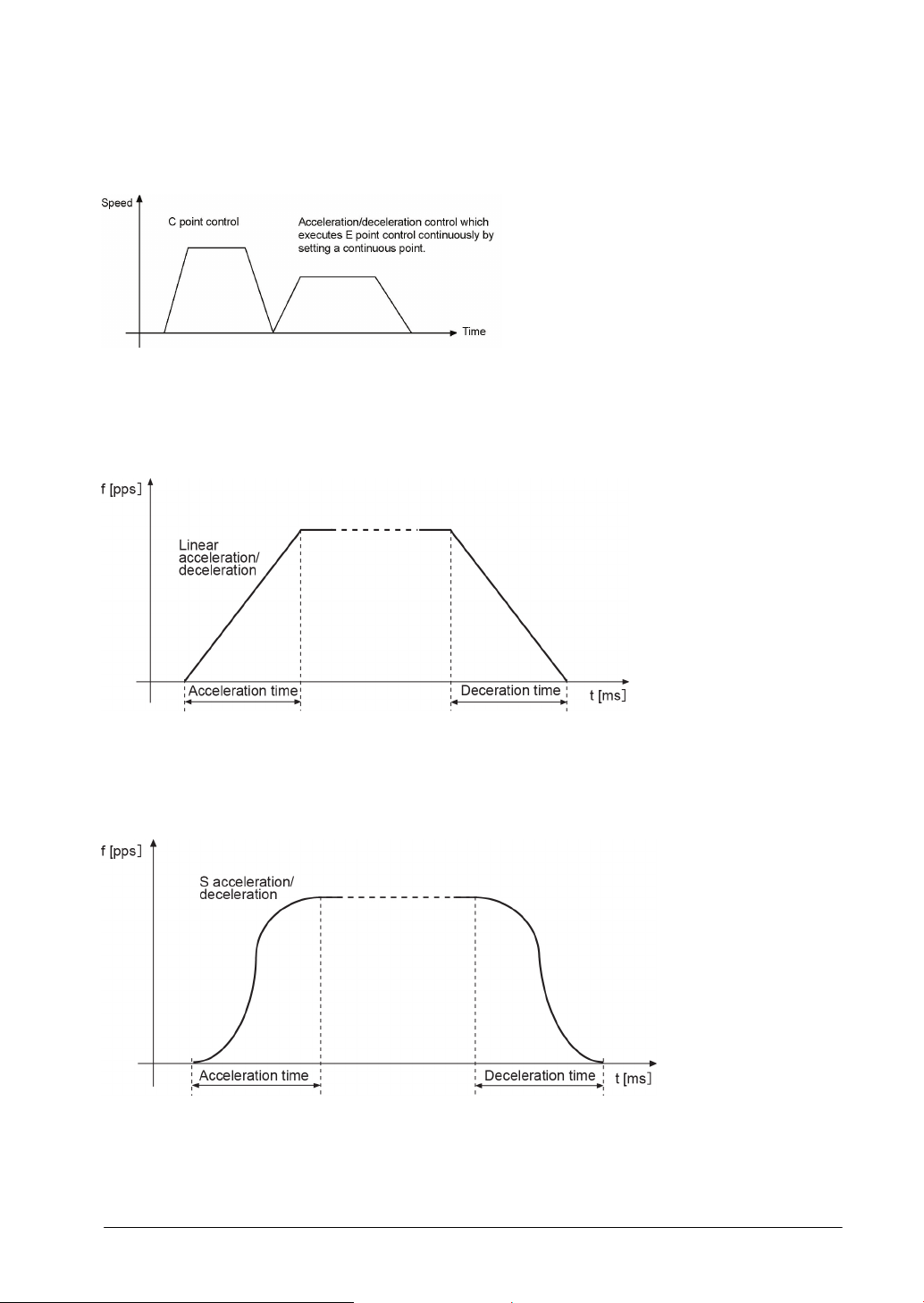
Linear acceleration/deceleration / S acceleration/deceleration
"Linear acceleration/deceleration" or "S acceleration/deceleration" is selectable for the
acceleration/deceleration method. With linear acceleration/deceleration, acceleration and deceleration
between the startup and the target speed are carried out in a straight line. Acceleration and deceleration
take place at a constant percentage.
The S acceleration/deceleration performs acceleration or deceleration curvedly.
Acceleration/deceleration is performed relatively slow at the beginning, and gradually increased.
Acceleration/deceleration is performed slowly as approaching the end of it. The movement is relatively
smooth. Acceleration/deceleration is complete in an acceleration/deceleration time specified in the
shared memory.
vii
Acceleration time/deceleration time
For the E point control or C point control, the acceleration time is the time during which the speed
changes from the startup speed of a motor to the target speed. The deceleration time is the time during
which the speed changes from the target speed to the stop. For the P point control, the acceleration time
is the time during which the speed accelerates form the current speed to the next target speed, and the
deceleration time is the time during which the speed decelerates from the current speed to the next
target speed.
CW, CCW
Generally, these indicate the direction in which the motor is rotating, with CW referring to clockwise
rotation and CCW to counterclockwise rotation.
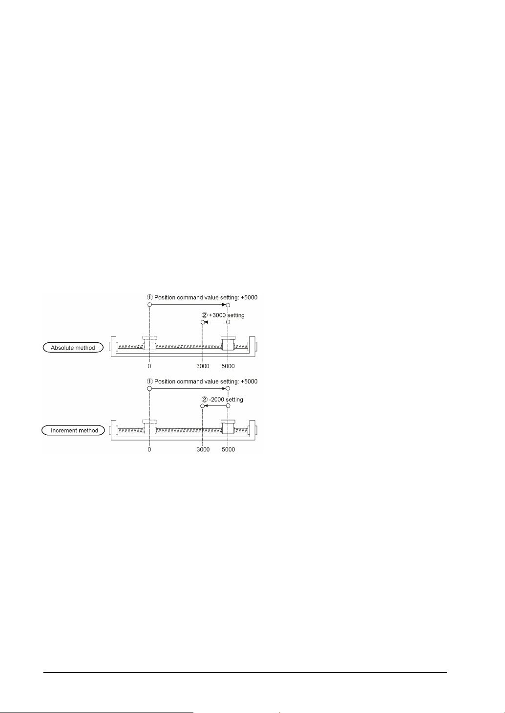
Absolute method (absolute value control method)
This is a control method in which the target position is specified as an absolute position from the home
position. This is specified on the positioning data editing screen of the Configurator PM.
Increment method (relative value control method)
This is a control method in which the distance from the current position to the target position is specified
as a relative position. This is specified on the positioning data editing screen of the Configurator PM.
Automatic operation
This is an operation to be automatically executed, and means a position control.
Manual operation
This is an operation to be executed for an initial boot or adjustments. The home return, JOG operation
and pulser operation are manual operations.
Position control
This is a generic term for the E point control, P point control and C point control. For each control, the
control of a single axis and the interpolation control of multiple axes are available. The interpolation
control can be selected from a 2-axis linear interpolation, 2-axis circular interpolation, 3-axis linear
interpolation and 3-axis spiral interpolation.
JOG operation
This refers to an operation in which the motor is rotated only while operation commands are being input.
This is used to forcibly rotate the motor using input from an external switch, for instance when to make
adjustments. Depending on the circumstances, this can also be applied to unlimited feeding in some
cases.
viii

Home return
The reference position for positioning is called a Home position and an operation to travel to a Home
position is called Home return. The home position should be set in advance. This operation moves to the
home position and its coordinate is set to be 0.
The motor rotation is reversed automatically when the limit input (+) or the limit input (-) is input and the
home position or the near home position is searched to return to the home position automatically.
Pulser operation
A manual operation is available using a device (pulser) which generates pulses manually. The output
similar to an encoder is obtained from the pulser, and the positioning unit RTEX is equipped with
exclusive input terminals. It is also called a manual pulse generator.
Deceleration stop
This is a function that interrupts the operation in progress, slows the rotation and brings it to a stop. The
deceleration time can be specified individually.
Emergency stop
This is a function that interrupts the operation in progress, slows the rotation and brings it to a stop.
Generally, a time shorter than a time for a deceleration stop is set. The deceleration time can be
specified individually.
Positioning table (Table)
A series of positioning data such as acceleration/deceleration time, target speed and interpolation
operation that is necessary for a position control is managed as a positioning table. For example, one
table is necessary for the E point control, and multiple tables are necessary for the P point control and C
point control depending on the number of pass points and continuance points.
Limit input (+), limit input (-)
This is an input to set a limit the motor movement. Limit input (+) is the maximum limit and the limit input
(-) is the minimum limit. They are connected to the AMP for the positioning unit RTEX.
Near home (DOG) input
In order to stop the table at the home position, a position at which deceleration begins is called the near
home position. This is connected to an external input switch or sensor. It is connected to the AMP for the
positioning unit RTEX.
Dwell time
In case of the E point control, a time from the completion of a position command until the operation done
flag turns on can be specified as a dwell time. In case of the C point control, a time from the deceleration
stop until the next table activates can be specified.
ix

Auxiliary output code, auxiliary output contact
They are used to check the operation of a position control.
The auxiliary output code is a 16-bit code that can be specified for each positioning table, and enables to
monitor which positioning table is being executed.
The execution of the position control can be confirmed by turning an exclusive auxiliary output contact on
for a constant time.
Software limit
Limits in software can be set for the absolute coordinate managed within the positioning unit RTEX.
When exceeding the setting range of the software limit, an error occurs, and the system decelerates and
stops. The deceleration time can be set individually.
Torque limit
The output torque of the AMP can be limited arbitrary.
Servo lock/Servo free
According the command from the positioning unit, the state that the motor is controllable is called a servo
lock state, and the state that the motor is uncontrollable is called a servo free state. The servo on
operation is necessary to make it to the servo lock state.
Servo ON/Servo OFF
The operation that changes the servo free state to the servo lock state is called a servo on, and the
operation that changes the servo lock state to the servo free state is called a servo off.
Linear interpolation
This is the interpolation control that controls positions as the locus of the operations of the 2-axis motor
with the grouped X axis and Y axis or 3-axis motor with the grouped X axis, Y axis and Z axis becomes a
straight line. There are two setting methods, which are a composition speed specification and long axis
speed specification.
Circular interpolation
This is the interpolation control that controls positions as the locus of the operation of the 2-axis motor
with the grouped X axis and Y axis becomes a circular arc. There are two setting methods, which are a
center point specification and pass point specification.
Spiral interpolation
This is the interpolation control that controls positions as the locus of the operation of the 3-axis motor
with the grouped X axis, Y axis and Z axis becomes a spiral. Arbitrary 2 axes describe an arc, and the
remaining one axis moves to achieve a spiral. There are two setting methods, which are a center point
specification and pass point specification.
Edge type
This is one of the methods to detect the request signals allocated to this unit. It executes each requested
process by detecting a trigger that is the leading edge when the request signal turns on.
Therefore, the next request cannot be accepted until the request signal turns off.
Level type
This is one of the methods to detect the request signals allocated to this unit. It executes each requested
process by detecting a trigger that the request signal is on, and continues the requested process while
the request signal is on.
x
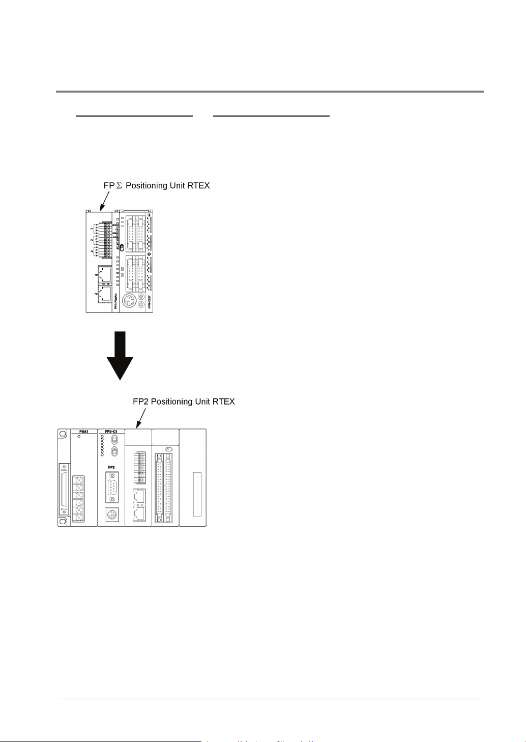
About Illustrations in This Manual
The FPΣ Positioning Unit RTEX and FP2 Positioning Unit RTEX are described in this manual.
The illustrations in this manual shows the status with the FPΣ.
If you use the FP2, please replace the illustrations of the FPΣ with the following illustration.
xi

xii

Chapter 1
Functions of Unit and Restrictions on
Combination
1.1 Functions of Positioning Unit RTEX
1.1.1 Functions of Unit
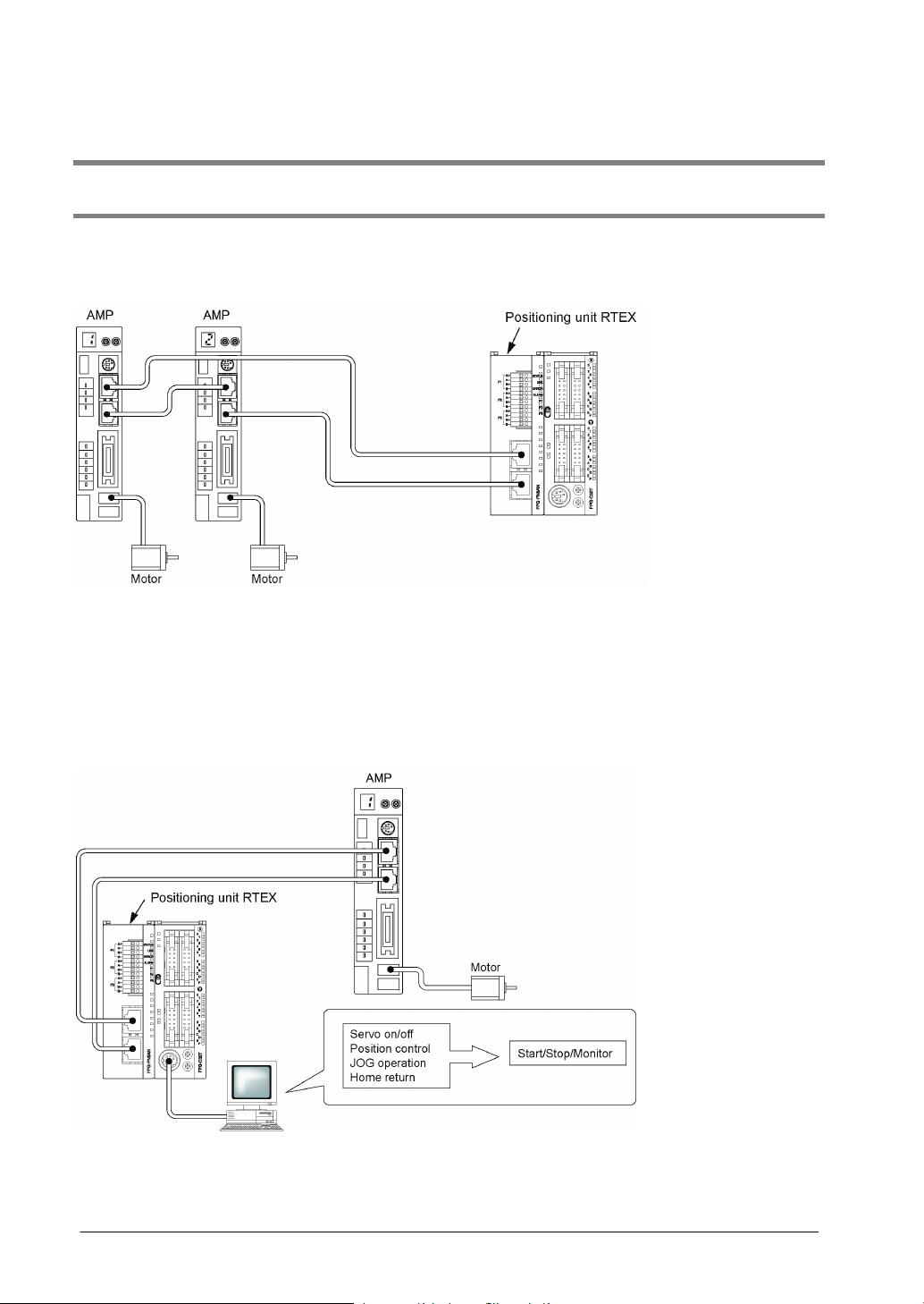
Network control
The motion-only network Realtime Express (RTEX) enables to easily construct a system of network
servo motors using the cables with a category 5e shield.
Configuration of axes according to the system
In accordance with the number of required axes, 2-axis, 4-axis and 8-axis unit are available.
Can confirm operations without ladder programs
Using the tool operation function of the Configurator PM enables a test run without a ladder program,
and enables to confirm various items such as the rotating direction, various input contacts or automatic
operation settings.
Two-axis and three-axis interpolation controls
The 2-axis linear interpolation, 2-axis circular interpolation, 3-axis linear interpolation and 3-axis spiral
interpolation controls can be performed.
1-2
I/O required for the control is aggregated in the AMP
Type
Function
Part number
Product number
2-axis type
2-axis control
FPG-PN2AN
AFPG43610
4-axis type
4-axis control
FPG-PN4AN
AFPG43620
8-axis type
8-axis control
FPG-PN8AN
AFPG43630
Type
Function
Part number
Product number
2-axis type
2-axis control
FP2-PN2AN
AFP243610
4-axis type
4-axis control
FP2-PN4AN
AFP243620
8-axis type
8-axis control
FP2-PN8AN
AFP243630
Name
Specifications
Product number
Control Configurator PM
English
AFPS66510
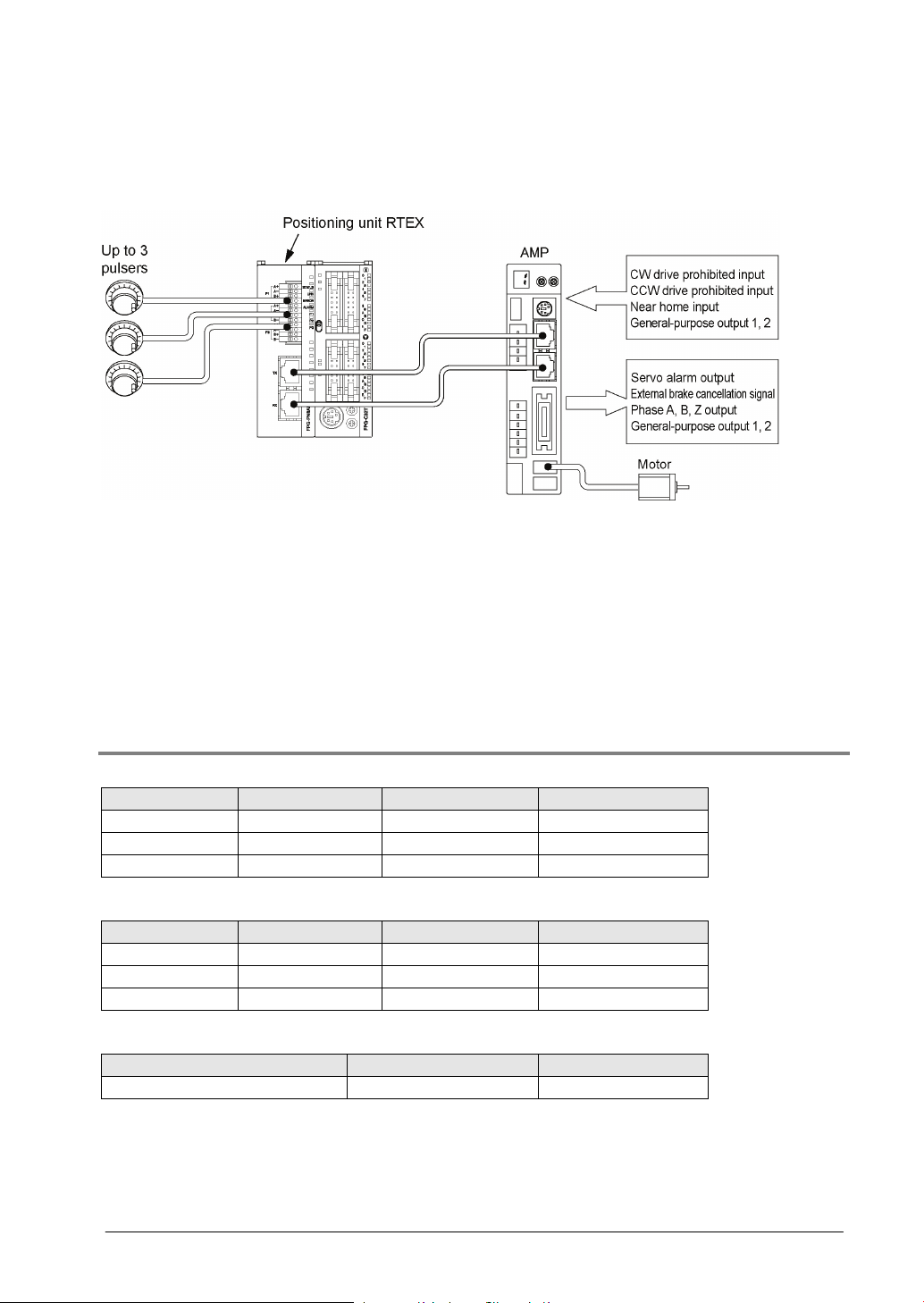
As the limit input and near home input is connected to the AMP and given to the positioning unit RTEX
through the network, the wiring can be simplified.
Remote I/O of 2-input and 2-output for one AMP
The 2-point general purpose input and output (transistors) can be connected to the AMP, and they can
be programmed by the X contact and Y contact of the positioning unit RTEX. The input and output
neighboring the AMP can be used as the remote I/O.
Supports the manual pulser
The maximum of three manual pulsers can be connected. It is possible to change the axes
corresponding to each pulser by the setting of the positioning unit RTEX.
1.1.2 Unit Types
FPΣ Positioning Unit RTEX
FP2 Positioning Unit RTEX
Setting software
1-3
1.2 Restrictions on Units Combination
Type
Part number
Product number
Current consumption (from power supply)
2-axis type
FP2-PN2AN
AFP243610
300 mA
4-axis type
FP2-PN4AN
AFP243620
300 mA
8-axis type
FP2-PN8AN
AFP243630
300 mA
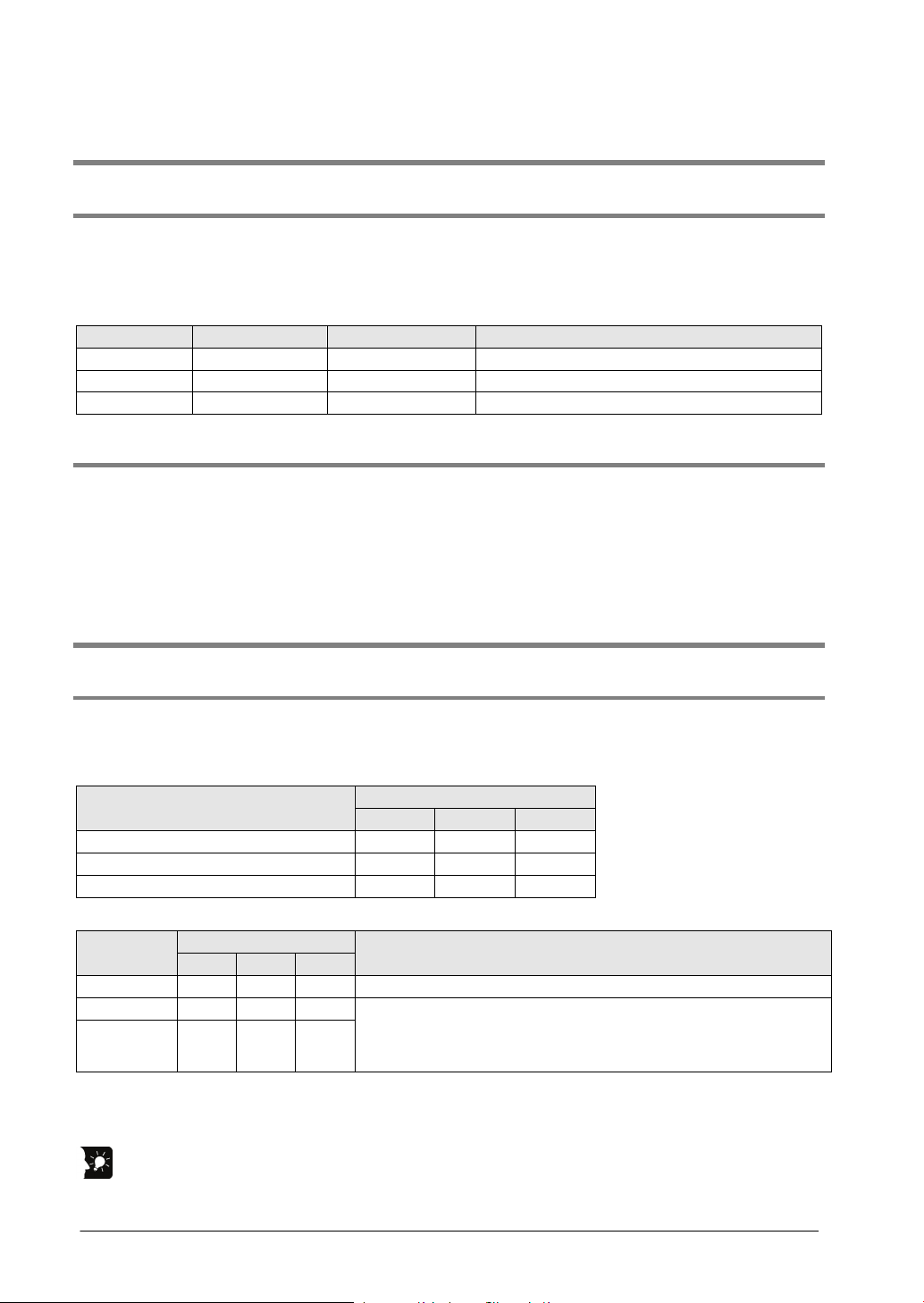
Connectable AMP
A4N
A5N
A6N
Ver.1.0 or later
A - -
Ver.1.3 or later
A A -
Ver.1.4 or later
A A A
Connectable AMP
A4N
A5N
A6N
A4N A - - Only A4N can be connected to the same network.
A5N - A
A
A5N and A6N can be connected to the same network. A4N
be performed.
1.2.1 Restrictions on Combinations Based on Current Consumption (FP2 only)
For the FP2, when the system is designed, the other units being used should be taken into consideration,
and a power supply unit with a sufficient capacity should be used. (For the FPΣ, there is no restrictions
based on the current consumption.)
FP2 Positioning Unit RTEX
1.2.2 Restrictions on the Number of Units Installed
FPΣ Positioning Unit RTEX
The maximum of 2 units can be installed.
FP2 Positioning Unit RTEX
There is no restriction on the number of units installed if it is within the restrictions on the current
consumption.
1.3 Restrictions on Unit and AMP
1.3.1 Restrictions on Combination of Unit and AMP
As for the combination of the positioning unit RTEX and each MINAS series, confirm the following
restrictions.
Combination of Positioning Unit RTEX and AMP A: Available -: Not available
Version of Positioning Unit RTEX
Combination of AMP series A: Available -: Not available
AMP type
A6N - A A
Setting ranges of movement amount and speed
The input range of the movement amount or speed specified in the positioning unit RTEX may differ from
the set upper and lower limits of AMP.
Key Point:
- A5N and A6N can be used connecting to the same network.
Description
cannot be connected to the same network. When A4N is used,
the AMP communication error occurs and the operation cannot
1-4

1.3.2 Restrictions on AMP Parameters
Factory
setting
disabled)".
Selection of command
update period
Some parameters of AMPs affect the operation of the positioning unit RTEX. Set parameters according
to the following description.
[A4N parameters]
No. Parameter name
02 Control mode 0 Use "setting value 0 (position control)".
03 Selection of torque limit 1
04 Over-travel inhibit input 1
09 Unit of velocity 0 Use "Pulse/s".
Parameter change via
0A
network
43 Direction of motion 1
5E Setup of 1st torque limit 500
74
default
0
2 Use "setting value 2 (1 ms)".
Settings
The positioning unit automatically changes the setting.
Do not change this parameter.
Use "setting value 1 (Over-travel inhibit input is
Use "setting value 0 (Enable)".
When setting "setting value 1 (inhibit)", parameters
cannot be changed from the positioning unit RTEX.
The positioning unit automatically changes the setting.
Do not change this parameter.
1-5

[A6N/A5N parameters]
Factory
setting
setup
setting. Do not change this parameter.
Pr0.01
Control mode setup
0
Use "setting value 0 (semi-closed control)".
revolution
Numerator of electronic
gear
electronic gear
Pr4.00
Pr4.07
setup
disabled)".
cycle setup
RTEX command
setting
extended setup 1
No. Parameter name
Pr0.00
Pr0.08
Pr0.09
Pr0.10
to
Pr5.04
Pr5.21 Selection of torque limit 1
Pr7.20
Pr7.21
Rotational direction
Number of command
pulses per motor
Denominator of
SI1 - SI8 input
selection
Over-travel inhibit input
RTEX communication
updating cycle ratio
default
1
0
1
1
(Note2)
1
3 Use "setting value 3 (0.5 ms)".
2 Use "setting value 2 (2 times)".
Settings
The positioning unit automatically changes the
Factory default setting
When Pr.0.08=0, Pr.0.09=1, Pr.0.10=1, position
command input is position command.
(Note 1)
The connection method and settings vary according
to the home return method used.
Use "setting value 1 (Over-travel inhibit input is
The positioning unit automatically changes the
setting. Do not change this parameter.
Pr7.22
Pr7.23
Pr7.25 RTEX Speed unit setup 0 Change to "setting value 1 (command unit/s)".
(Note 1) For details of Pr0.08 to Pr0.10, refer to "Technical Reference of AC Servo Driver A5N series" or
"Technical Reference of AC Servo Driver A6N series".
(Note 2) The factory default settings of Pr4.00 to Pr4.07 vary according to parameter numbers. For
details of the setting methods, refer to "10.2 AMP Settings and Usable Home Return Methods
RTEX function
RTEX function
extended setup 2
0 Use "setting value 0 (16-byte mode)".
18
The positioning unit automatically changes the
setting. Do not change this parameter.
1-6

Chapter 2
Parts and Functions
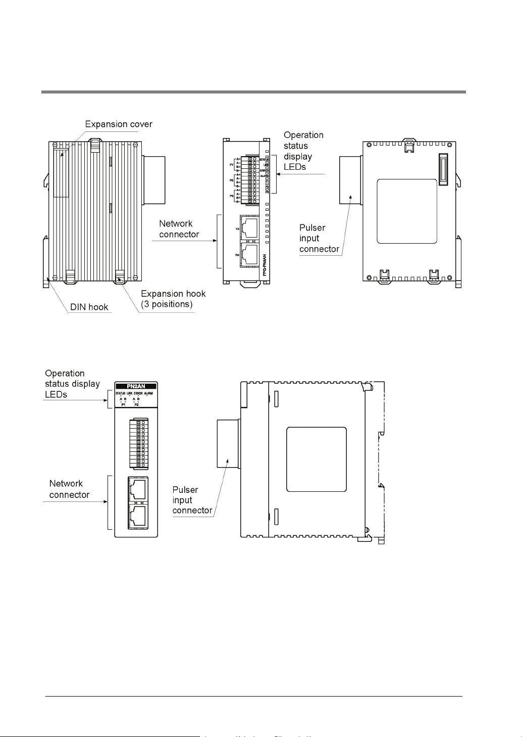
2.1 Parts and Functions
FPΣ Positioning Unit RTEX
FP2 Positioning Unit RTEX
2-2

2.2 Operation Status Display LEDs
Name
Color
Status
Remarks
STATUS
Green
LED blinks:
LED on:
Waiting for network
Network establishment
connected properly.
ERROR
Red
LED off:
Normal
In case of warning, the
operation stops.
ALARM
Red
LED off:
Normal
If the LED turns on, the
turned off and on again.
P1
Green
LED off:
B are in the on state
Check the input signals
Name
Color
Status
Remarks
STATUS
Green
LED blinks:
LED on:
Waiting for network
Network establishment
LINK
Green
LED off:
Not connected
The state that the TX of the sending
electrically connected properly.
ERROR
Red
LED off:
LED on:
Normal
An error occurred.
In case of warning, the operation
In case of error, the operation stops.
ALARM
Red
LED off:
LED on:
Normal
System error
If the LED turns on, the power supply
should be turned off and on again.
P1A
P3B
Green
LED off:
Off state
Check the input signals of the pulsers.
FPΣ Positioning Unit RTEX
LINK Green LED off:
P2
P3
FP2 Positioning Unit RTEX
LED on:
LED blinks:
LED on:
LED on:
LED on:
establishment
Not connected
Normal connection
A warning occurred.
An error occurred.
System error
Both phase A and phase
B are in the off state.
Both phase A and phase
The state that the TX of
the sending node and
the RX of the own node
are electrically
operation continues.
In case of error, the
power supply should be
of the pulsers.
LED on:
LED blinks:
P1B
P2A
P2B
P3A
2-3
LED on:
establishment
Normal connection
A warning occurred.
On state
node and the RX of the own node are
continues.

2-4

Chapter 3
Wiring
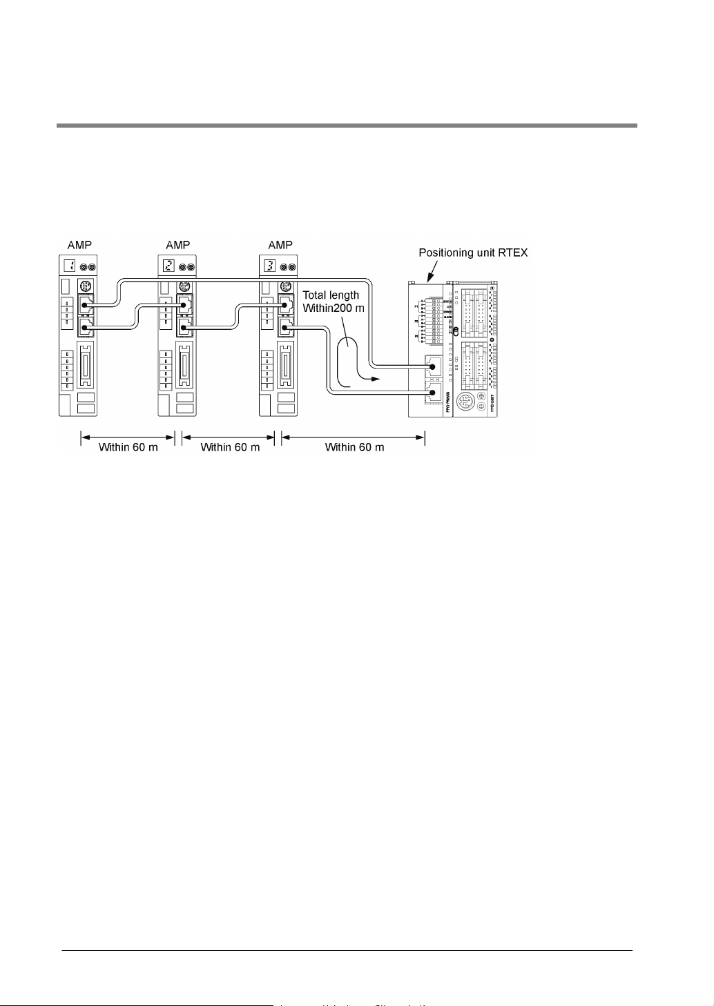
3.1 Wiring of Network
Use the LAN cable with the category 5e shielded type for the wiring of the network. To prevent the cable
from coming off, securely connect the connector of the cable to the network connector (RJ45 connector)
of the unit.
The length between each node should be within 60 m, and the total length of the communication loop
should be within 200 m.
3-2
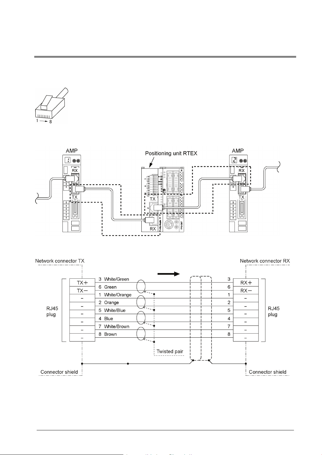
3.2 Network Connector
RJ45 plug is connected to the network connector.
Pins of RJ45 plug
Connecting diagram
3-3
3.3 Wiring of Pulser Input Connector
Manufacturer
Number of pins
Part No.
Product No.
Phoenix Contact Co.
12 pins
FK-MC0, 5/12-ST-2,5
1881422
Suitable wires
Tightening torque
AWG# 28 to 20
0.14 to 0.5 mm2
Cross-sectional area
(mm2)
0.25
AWG #24
A 0, 25-7
0.34
AWG #22
A 0, 34-7
0.50
AWG #20
A 0, 5-6
Manufacturer
Part No.
Product No.
Phoenix Contact Co.
CRIMPFOX 10S
1212045
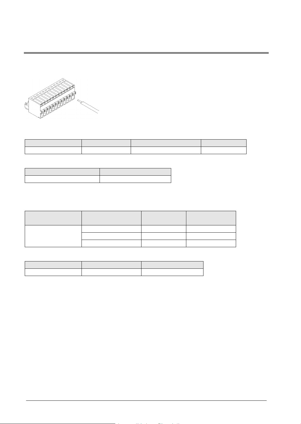
Supplied connector/Suitable wire
A connector of the spring connection type is used. Use the following suitable wires for the wiring.
Supplied connector socket
The connector socket manufactured by Phoenix Contact Co. should be used.
Suitable wires (strand wire)
Pole terminal with a compatible insulation sleeve
If a pole terminal is being used, the following models manufactured by Phoenix Contact Co. should be
used.
Manufacturer
Phoenix Contact Co.
Pressure welding tool for pole terminals
For tightening the connector
For inserting the wires, use a screwdriver (Phoenix contact Co., Product No. 1205202) with a blade size
of 0.4 × 2.0 (Part No. SZS 0,4×2,0).
Size Part No.
3-4

Wiring method
(1) Remove a portion of the wire’s insulation.
(2) Press the orange switch of the connector using a tool such as a flat-blade screwdriver.
(3) Insert the wire into the connector until it stops with pressing the orange switch.
(4) Take the tool off the switch.
Precautions on wiring
• When removing the wire’s insulation, be careful not to scratch the core wire.
• Do not twist the wires to connect them.
• Do not solder the wires to connect them. The solder may break due to vibration.
• After wiring, make sure stress is not applied to the wire.
3-5
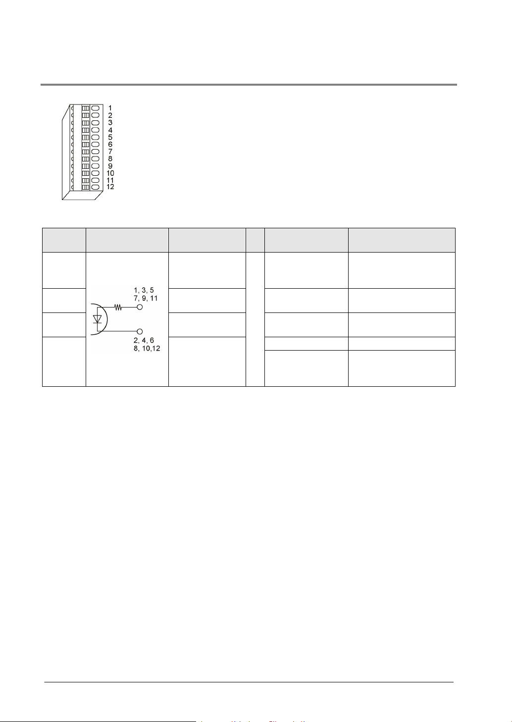
3.3.1 Input Specifications and Pin Configuration
number
3.5 to 5.25 V DC
specifications)
voltage/current
Maximum ON
voltage/current
Input impedance
Approx. 390 Ω
phase)
Input terminals of pulser input connector
Pin
1, 5, 9
2, 6, 10 Pulse input A (-)
3, 7, 11 Pulse input B (+)
4, 8, 12 Pulse input B (-)
Note) When the pulser is connected to the pulse input, the elapsed value increases if the phase A is
proceeding more than the phase B.
Circuit Signal name Item Descriptions
Pulse input A (+)
Operating voltage
range
Minimum ON
Input specifications
Minimum input
pulse width
(5 VDC, line driver
3 V DC/4 mA
1 V DC/2.0 mA
0.5 µs or more
(Max. 1 MHz for each
3-6
 Loading...