

Panasonic FPG-C32T2TM, FPG-C32T, FPG-C28P2, FPG-C32TH, FPG-C28P2TM User Manual
...

Safety Precautions
Observe the following notices to ensure personal safety or to prevent accidents.
To ensure that you use this product correctly, read this User’s Manual thoroughly before use.
Make sure that you fully understand the product and information on safe.
This manual uses two safety flags to indicate different levels of danger.
WARNING
If critical situations that could lead to user’s death or serious injury is assumed by
mishandling of the product.
-Always take precautions to ensure the overall safety of your system, so that the whole
system remains safe in the event of failure of this product or other external factor.
-Do not use this product in areas with inflammable gas. It could lead to an explosion.
-Exposing this product to excessive heat or open flames could cause damage to the lithium
battery or other electronic parts.
CAUTION
If critical situations that could lead to user’s injury or only property damage is assumed
by mishandling of the product.
-To prevent abnormal exothermic heat or smoke generation, use this product at the values less
than the maximum of the characteristics and performance that are assure in these specifications.
-Do not dismantle or remodel the product. It could lead to abnormal exothermic heat or
smoke generation.
-Do not touch the terminal while turning on electricity. It could lead to an electric shock..
-Use the external devices to function the emergency stop and interlock circuit.
-Connect the wires or connectors securely.
The loose connection might cause abnormal exothermic heat or smoke generation
-Do not allow foreign matters such as liquid, flammable materials, metals to go into the
inside of the product. It might cause exothermic heat or smoke generation.
-Do not undertake construction (such as connection and disconnection) while the power
supply is on.
Copyright / Trademarks
-This manual and its contents are copylighted.
-You may not copy this manual,in whole or part,without written consent of Matsushita Electric
Works,Ltd.
-Windows and Windows NT are registered trademarks of Microsoft Corporation in the
United States and/or other countries.
-All other company names and product names are trademarks or registered
trademarks of their respective owners.
-Matsushita Electric Works,Ltd. pursues a policy of continuous improvement of the
Design and performan e of its products, therefore,we reserve the right to change the manual/ c
product without notice.

Table of Contents
Before You Start
Programming Tool Restrictions
When Changing Ladder Program from 12k Type to 32k Type
Compatibility with FP0
1. Functions and Restrictions of the Unit 1-1
1.1 Features and Functions of the Unit 1-2
1.2 Unit Types
1.2.1 FPΣ Control Unit
1.2.2 FPΣ Expansion Unit
1.2.3 FP0 Expansion Unit
1.2.4 Communication Cassette
1.3 Restrictions on Unit Combinations
1.3.1 Restrictions on FP0 Expansion Unit
1.4 Programming Tools
1.4.1 Tools Needed for Programming
1.4.2 Software Environment and Suitable Cable
1-6
1-6
1-7
1-8
1-8
1-9
1-9
1-11
1-11
1-11
2. Specifications and Functions of the Unit 2-1
2.1 Parts and Functions 2-2
2.2 Input and Output Specifications
2.2.1 Input Specifications
2.2.2 Output Specifications
2.3 Terminal Layout Diagram
2.3.1 Control Unit (for C32)
2.3.2 Control Unit (for C28)
2.3.3 Control Unit (for C24)
2-6
2-6
2-8
2-11
2-11
2-12
2-12
2.4 Analog Potentiometer
2.4.1 Overview of Analog Potentiometer
2.5 Thermister Input (Only for TM type)
2.5.1 Overview of Thermister Input
2.5.2 Loading of Thermister Temperature Data
2.6 Calendar Timer
2.6.1 Area for Clock/Calendar Function
2.6.2 Setting of Clock/Calendar Function
2.6.3 Example Showing the Clock/Calendar being Used
2.6.4 30-second Compensation Sample Program
2-13
2-13
2-14
2-14
2-16
2-17
2-17
2-17
2-18
2-19

3. Expansion 3-1
3.1 Type of Expansion Unit 3-2
3.2 Expansion Method of Units for FP0 and FPΣ
3.3 Expansion Method of FPΣ Expansion Unit
3.4 Specifications of FPΣ Expansion Unit
3.4.1 FPΣ Expansion Unit
3.4.2 FPΣ Expansion Data Memory Unit
3.4.3 Other Expansion Units
3-3
3-4
3-5
3-5
3-9
3-12
4. I/O Allocation 4-1
4.1 I/O Allocation 4-2
4.2 Allocation of FPΣ Control Unit
4.3 Allocation of FPΣ Expansion Unit
4.3.1 I/O Numbers of FPΣ Expansion Unit
4.4 Allocation of FP0 Expansion Unit
4.4.1 I/O Numbers of FP0 Expansion Unit
4-3
4-4
4-4
4-5
4-5
5. Installation and Wiring 5-1
5.1 Installation 5-2
5.1.1 Installation Environment and Space
5.1.3 Installation Using the Optional Mounting Plate
5.2 Wiring of Power Supply
5.2.1 Wiring of Power Supply
5.2.2 Grounding
5.3 Wiring of Input and Output
5.3.1 Input Wiring
5.3.2 Output Wiring
5.3.3 Precautions Regarding Input and Output Wirings
5.4 Wiring of MIL Connector Type
5.5 Wiring of Terminal Block Type
5.6 Safety Measures
5.6.1 Safety Measures
5.6.2 Momentary Power Failures
5.6.3 Protection of Power Supply and Output Sections
5.7 Installation and Setting of Backup Battery
ii
5-2
5-5
5-8
5-8
5-10
5-11
5-11
5-13
5-14
5-15
5-17
5-19
5-19
5-19
5-20
5-21

5.7.1 Installation of Backup Battery
5.7.2 System Register Setting
5.7.3 Time for Replacement of Backup Battery
5.7.4 Lifetime of Backup Battery
5-21
5-22
5-22
5-23
6. High-speed counter, Pulse Output and PWM Output functions 6-1
6.1 Overview of Each Functions 6-2
6.1.1 Three Functions that Use Built-in High-speed Counter
6.1.2 Performance of Built-in High-speed Counter
6.2.1 Specifications
6.2.2 Functions Used and Restrictions
6.2.3 Booting Time
6-2
6-3
6-4
6-6
6-9
6.3 High-speed Counter Function
6.3.1 Overview of High-speed Counter Function
6.3.2 Input Modes and Count
6.3.3 Minimum Input Pulse Width
6.3.4 I/O Allocation
6.3.5 Instructions used with High-speed Counter Function
6.3.6 Sample program
6.4 Pulse Output Function
6.4.1 Overview of Pulse Output Function
6.4.2 Types of Pulse Output Method and Operation Modes
6.4.3 I/O Allocation
6.4.4 Pulse output control instructions (F0) (F1)
6.4.5 Positioning Control Instruction F171 - Trapezoidal Control (Common to Transistor
type)
6.4.6 Positioning Control Instruction F171 – Home Return (Common to Transistor type)
6.4.7 Pulse Output Instruction F172 – JOG operation (Common to Transistor type)
6.4.8 Positioning Control Instruction F174 – Data Table Contro.
6.4.9 Action of the Flag concerning Linear Interpolation and Circular Interpolation
6.4.10 Pulse Output Instruction F175 – Linear Interpolation (Only for C32T2, C28P2,
C32T2H and C28P2H)
6.4.11 Pulse Output Instruction F176 – Circular Interpolation (Only for C32T2, C28P2,
C32T2H and C28P2H)
6.5 PWM Output Function
6.5.1 Overview
6.5.2 PWM Output Instruction F173
6-10
6-10
6-10
6-11
6-12
6-12
6-15
6-18
6-18
6-19
6-21
6-22
6-25
6-30
6-36
6-40
6-42
6-48
6-50
6-59
6-59
6-59
7. Communication Cassette 7-1
7.1 Functions and Types 7-2
7.1.1 Functions of Communication Cassette
7.1.2 Types of Communication Cassette
7.1.3 Names and Principle Applications of the Ports
7.1.4 Setting of AFPG806 Switch
7.2 Communication Specifications
7-2
7-6
7-9
7-9
7-10
iii

7.2.1 Precaution When Using RS485 Port
7-12
7.3 Installation and Wiring
7.3.1 Installation of Communication Cassette
7.3.2 Wiring
7.3.3 Cables
7.4 Communication Function 1: Computer Link
7.4.1 Computer Link
7.4.2 1:1 Communication (Computer link)
7.4.3 1:N Communication (Computer Link)
7.4.4 MEWTOCOL Master (Sample Program) (Available For 32k Type Only)
7.5 Communication Function: General-purpose Serial Communication
7.5.1 General-purpose Serial Communication
7.5.2 Communication with External Devices
7.5.3 Connection with 1:1 Communication (General-purpose serial communication)
7.5.4 1:N Communication (General-purpose Serial Communication)
7.6 Communication Function 3: PC(PLC) link
7.6.1 PC(PLC) link
7.6.2 Setting Communication Parameters
7.6.3 Monitoring
7.6.4 Connection Example of PC(PLC) link
7.6.5 PC(PLC) link Response Time
7.7 Communication Function 4: MODBUS RTU Communication
7.7.1 MODBUS RTU Communication
7-14
7-14
7-15
7-17
7-18
7-18
7-26
7-29
7-34
7-36
7-36
7-39
7-49
7-61
7-62
7-62
7-64
7-73
7-74
7-78
7-82
7-82
8. Self-Diagnostic and Troubleshooting 8-1
8.1 Self-Diagnostic function 8-2
8.1.1 LED Display for Status Condition
8.1.2 Operation on Error
8.2 Troubleshooting
8.2.1 If ERROR/ALARM LED is Flashing
8.2.2 If ERROR/ALARM LED is ON
8.2.3 ALL LEDs are OFF
8.2.4 Diagnosing Output Malfunction
8.2.5 A Protect Error Message Appears
8.2.6 PROG Mode does not Change to RUN
8.2.7 A Transmission Error has Occurred through RS485
8.2.8 No Communication is Available through RS232C
8-2
8-2
8-3
8-3
8-4
8-5
8-6
8-7
8-7
8-8
8-8
9. Precautions During Programming 9-1
9.1 Use of Duplicated Output 9-2
9.1.1 Duplicated Output
9.1.2 When Output is Repeated with an OT, KP, SET or RST Instruction
iv
9-2
9-2

9.2 Handling BCD Data
9.2.1 BCD Data
9.2.2 Handling BCD Data in the PLC
9-4
9-4
9-4
9.3 Handling Index Registers
9.3.1 Index Registers
9.3.2 Memory Areas Which can be Modified with Index Registers
9.3.3 Example of Using an Index Register
9.4 Operation Errors
9.4.1 Outline of Operation Errors
9.4.2 Operation Mode When an Operation Error Occurs
9.4.3 Dealing with Operation Errors
9.4.4 Points to Check in Program
9.5 Instruction of Leading Edge Detection Method
9.5.1 Instructions of Leading Edge Detection Method
9.5.2 Operation and Precautions When RUN Starts
9.5.3 Precautions When Using a Control Instruction
9.6 Precautions for Programming
9.7 Rewrite Function During RUN
9.7.1 Operation of Rewrite During RUN
9.7.2 Cases Where Rewriting During Run is not Possible
9.7.3 Procedures and Operation of Rewrite During RUN
9.8 Processing During Forced Input and Output
9.8.1 Processing when forced input/output is initiated during RUN
9-5
9-5
9-5
9-6
9-7
9-7
9-7
9-7
9-8
9-9
9-9
9-10
9-11
9-13
9-14
9-14
9-15
9-17
9-19
9-19
10. Specifications 10-1
10.1 Table of Specifications 10-2
10.1.1 General Specifications
Performance Specifications
10.2 I/O No. Allocation
10.3 Relays, Memory Areas and Constants
10-2
10-5
10-12
10-14
11. Dimensions 11-1
11.1 Dimensions 11-2
11.1.1 Control Unit (Transistor Output Type)
11.1.2 Control Unit (Relay Output Type)
11.1.3 Expansion Unit
11.2 Connection Diagram with Motor Driver
11.2.1 Matsushita Electric Industrial Co., Ltd. MINAS A-series, AIII-series
11.2.2 Matsushita Electric Industrial Co., Ltd. MINAS Sseries, E-series
11.2.3 Power Supply Specification
11-2
11-3
11-4
11-5
11-5
11-5
11-6
v

12.Appendix 12-1
12.1 Table of System Registers 12-3
12.1.2 Table of System Registers for FPΣ 12-6
12.1.3 Table of Special Internal Relays for FPΣ 12-12
12.1.4 Table of Special Data Registers for FPΣ 12-21
12.2 Table of Basic Instructions 12-35
12.3 Table of High-level Instructions 12-69
12.4 Table of Error codes 12-129
12.5 MEWTOCOL-COM Communication Commands 12-143
12.6 Hexadecimal/Binary/BCD 12-144
12.7 ASCII Codes 12-145
vi

Before You Start
Installation environment
Do not use the FPΣ unit where it will be exposed to the following:
• Direct sunlight and ambient temperatures outside the range of 0°C to +55°C.
(When installing the unit in a control panel, carefully consider radiation. Also, do not install the unit
immediately above any devices generating heat.)
• Ambient humidity outside the range of 30% to 85% RH (at 25°C, non-condensing).
• Sudden temperature changes causing condensation.
• Inflammable or corrosive gas.
• Excessive airborne dust, metal particles or saline matter.
• Benzine, paint thinner, alcohol or other organic solvents or strong alkaline solutions such as ammonia
or caustic soda.
• Direct vibration, shock or direct drop of water.
• Influence from power transmission lines, high voltage equipment, power cables, power equipment,
radio transmitters, or any other equipment that would generate high switching surges.
Static electricity
• Before touching the unit, always touch a grounded piece of metal in order to discharge static electricity.
• In dry locations, excessive static electricity can cause problems.
Cleaning
• Do not use thinner based cleaners because they deform the unit case and fade colors.
Power supplies
• An insulated power supply with an internal protective circuit should be used. The power suppy for the
control unit operation is a non-insulated circuit, so if an incorrect voltage is directly applied, the
internal circuit may be damaged or destroyed.
• If using a power supply without a protective circuit, power should be supplied through a protective
element such as a fuse.
Power supply sequence
• Have the power supply sequence such that the power supply of the control unit turns off before the
power supply for input and output.
• If the power supply for input and output is turned off before the power supply of the control unit, the
control unit will detect the input fluctuations and may begin an unscheduled operation.
Before turning on the power
When turning on the power for the first time, be sure to take the precautions given below.
• When performing installation, check to make sure that there are no scraps of wiring, particularly
conductive fragments, adhering to the unit.
• Verify that the power supply wiring, I/O wiring, and power supply voltage are all correct.
• Sufficiently tighten the installation screws and terminal screws.
• Set the mode selector to PROG. Mode.
vii

Before entering a program
Be sure to perform a program clear operation before entering a program.
Operation procedure when using FPWIN GR Ver.2
Select “Online Edit Mode” on the FPWIN GR “On line” menu.
Select “Clear Program” on the “Edit” menu.
When the confirmation dialog box is displayed, click on “Yes” to clear the program.
Request concerning program storage
To prevent the accidental loss of programs, the user should consider the following measures.
• Drafting of documents
- To avoid accidentally losing programs, destroying files, or overwriting the contents of a file, documents
should be printed out and then saved.
• Specifying the password carefully
- The password setting is designed to avoid programs being accidentally overwritten. If the password is
forgotten, however, it will be impossible to overwrite the program even if you want to. Also, if a
possword is forcibly bypassed, the program is deleted. When specifying the password, note it in the
specifications manual or in another safe location in case it is forgotten at some point.
Operation procedure when using FPWIN GR Ver.2
Select “Online Edit Mode” on the FPWIN GR “On line” menu.
Select “Clear Program” on the “Edit” menu.
Battery
Do not install the battery when it is not used.
There is a possibility of leak if the battery remains discharged.
viii

Programming Tool Restrictions
Type of unit
FPG-C32T2
FPG-C28P2
Type of programming tool
FPWIN GR
Windows
software
Windows
software
Conforms to
IEC61131-3
MS-DOS
software
Handy
programming
unit
Note1) Either Ver. 2.13 or later is necessary for using FPΣ positioning unit.
Note2) Either Ver. 4.02 or later is necessary for using FPΣ positioning unit.
Ver.2
FPWIN GR
Ver.1
FPWIN Pro
Ver.5
FPWIN Pro
Ver.4
NPST-GR
Ver.4
NPST-GR
Ver.3
AFP1113V2
AFP1114V2
AFP1113
AFP1114
AFP1111A
AFP1112A
AFP1111
AFP1112
FPG-C32T
FPT-C32TTM
Used
Not used Not used Not used Not used
Used Used
Used
Not used Not used Not used Not used
Not used Not used Not used Not used
Not used Not used Not used Not used
Not used Not used Not used Not used
Not used Not used Not used Not used
FPG-C24R2
FPG-C32T2TM
FPG-C28P2TM
FPG-C24R2TM
Used
(Ver. 2.1 or
Note1)
later)
Used
(Ver. 4.01 or
later)
Note2)
FPG-C32TH
FPG-C32THTM
Used
(Ver. 2.6 or
later)
Used
(Ver. 5.2 or
later)
Not used Not used
FPG-C32T2H
FPG-C28P2H
FPG-C24R2H
FPG-C32T2HTM
FPG-C28P2HTM
FPG-C24R2HTM
Used
(Ver. 2.6 or
later)
Used
(Ver. 5.2 or
later)
Note: Precautions concerning version upgrade
• In case of using FPWIN GR Ver.1, please purchase upgrade model FPWIN GR Ver.2.
• FPWIN GR Ver. 2.0 can be upgraded to Ver. 2.1 or later free of charge at our web site
(
http://www.nais-j.com/plc/).
• FPWIN GR Ver. 4.0 can be upgraded to Ver. 4.1 or later free of charge at our web site
(
http://www.nais-j.com/plc/).
• FPWIN GR Ver. 5.0 can be upgraded to Ver. 5.1 or later free of charge at our web site
(
http://www.nais-j.com/plc/).
• In case of using FPWIN Pro Ver. 4.0 with FPΣ 32k type, please purchase upgrade model FPWIN GR
Ver.5.
ix
When Changing Ladder Program from 12k Type to 32k Type
It is necessary to convert the program to change the ladder program that is used for the FPΣ 12k
type to the one for FPΣ 32k type.
Program Conversion
When the FPWIN GR is used to change the model, the system register is automatically initialized
If the setting value has been changed from the default value, note it down before the program conversion
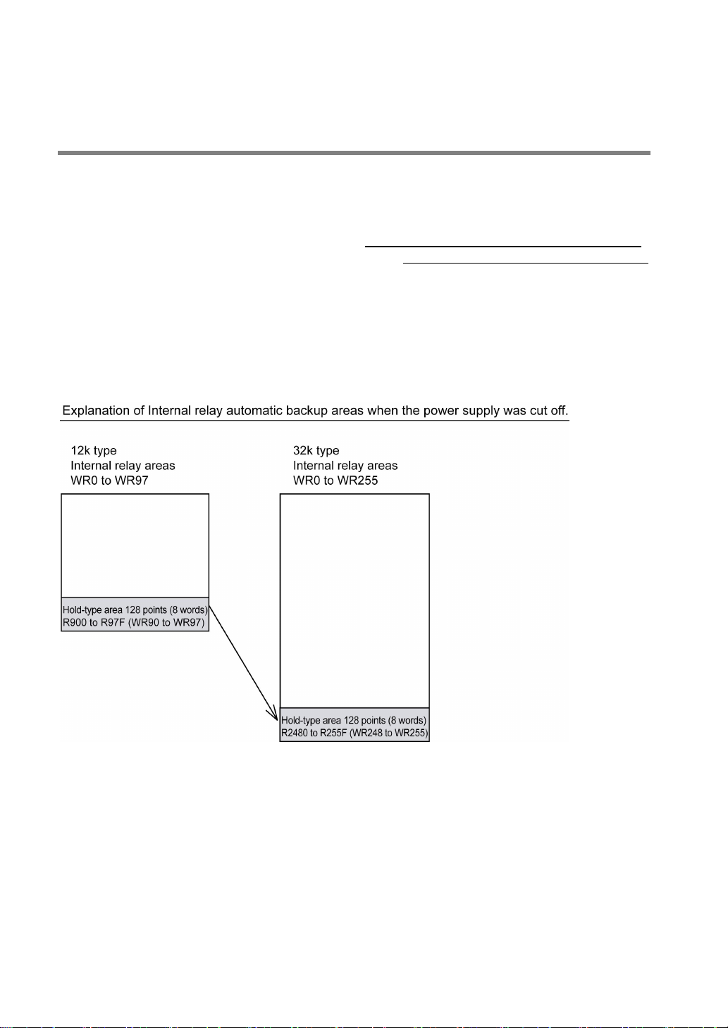
Number of points of internal relay for the 32k type is different from the 12k type.
The hold-type areas differ (automatic backup areas when the power supply was cut off) as the figure
shown below.
When the hold-type area in the internal relay is used, the program for that part should be converted.
(As the number of points for the counter, timer, DT and special DT is the same for the 12k type and 32k
type, the program conversion is not necessary.)
.
.
x
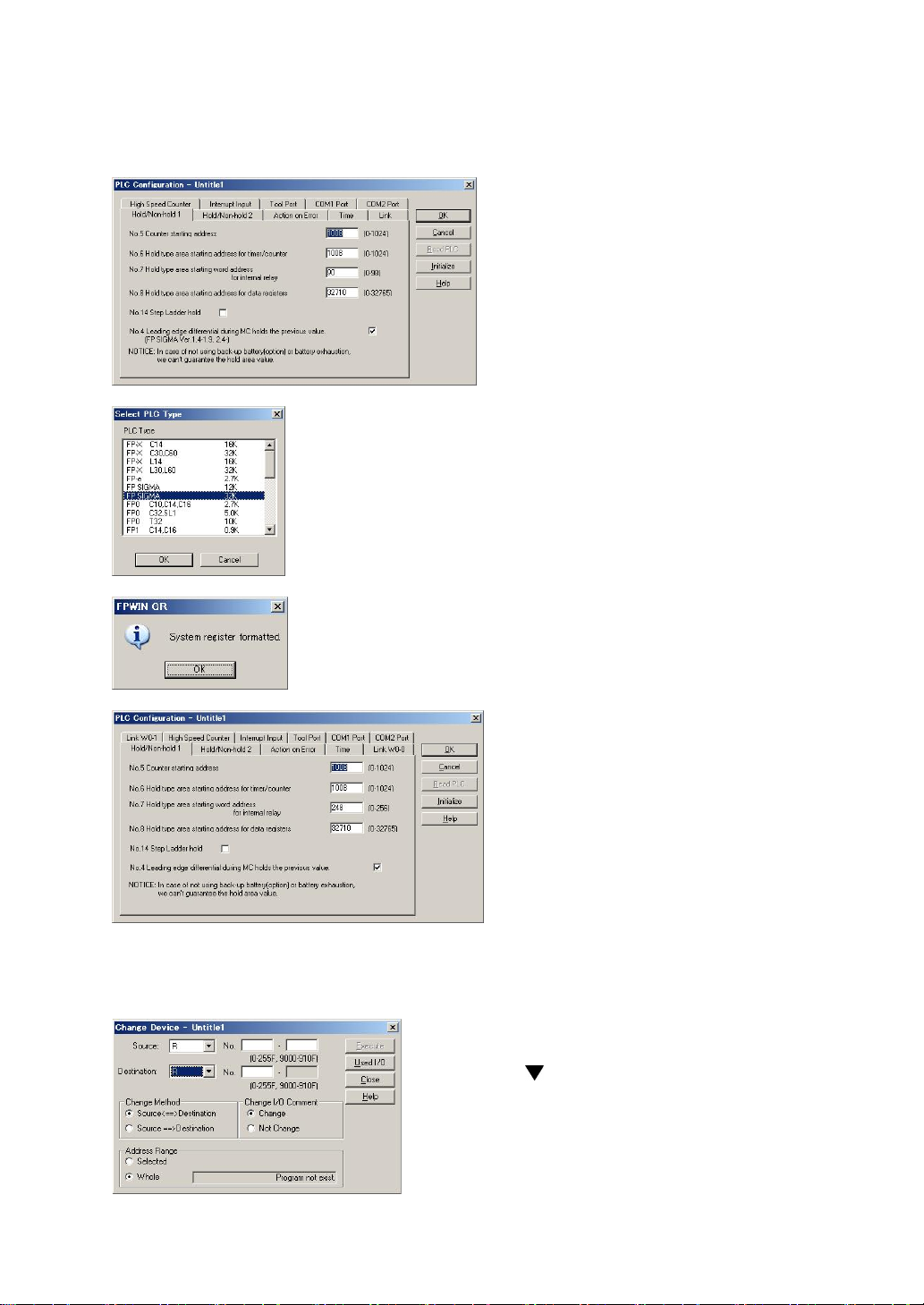
Procedure of Program Conversion
1. Retrieve a program to be converted with FPWIN GR.
2. Select “Option” → “PLC
Configuration” in the menubar.
Note down the setting value for the
system registers.
3. Select “Tool” → “Change PLC Type”.
Select “FPSIGMA 32K” and click “OK” button.
6. For the program using the hold-type area in the internal relay (R900 to R97F and WR90 to WR97), the
device should be changed to the hold-type area for the FPΣ 32k type (R2480 to R255F and WR248 to
WR255).
4. A message “System register formatted.” is indicated.
Click “OK” button.
5. Select “Option” → “PLC Configuration”.
Input the values noted down in procedure
2.
Note) When the battery is not used, the
system register No. 7 “Hold type area
starting word address for internal relay”
should be set to “248” that is the default
value for the FPΣ 32k type.
Select “Edit” → “Change Device”.
Click the
select “R” and “WR” from the pulldown menu, and
change the values.
buttons of “Source” and “Destination” to
xi
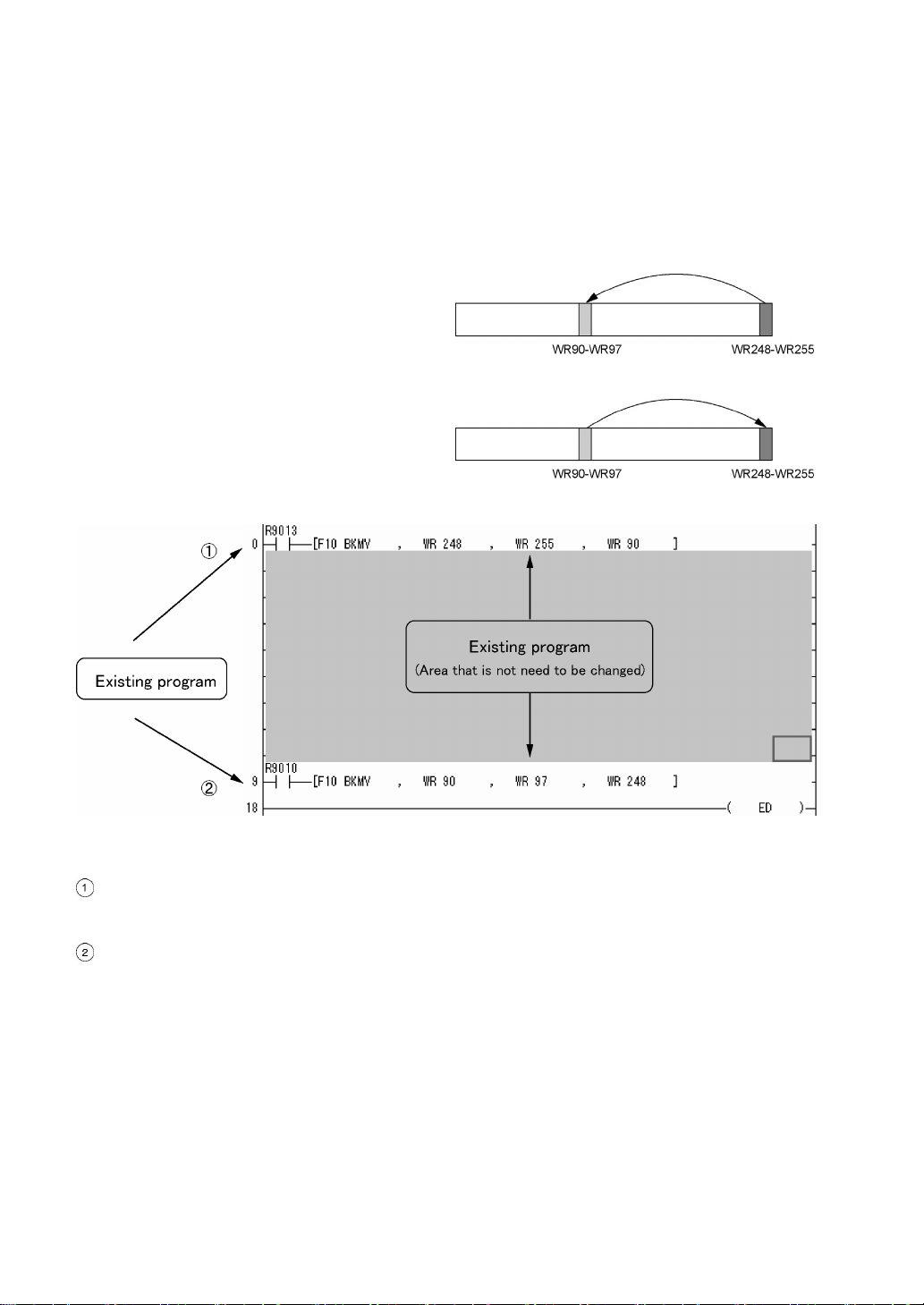
How to change an existing program
It is an easy method for chaging an existing program by partially adding a program without modifying the
exsiting program.
(When a programmable display is connected, it is not necessary to change the R and WR that are
referred for the switches and data parts in the programmable display.)
1. At the begnning of a program
Data in the hold-type area is transferred to the
existing area only once when the power supply
turns on.
2. At the end of a program
Data in the hold-type area is always transferred
to the existing area.
<Explanation of the program>
Transfers the contents stored in the hold-type area (WR248 to WR255) to the existing hold-type area
WR90 to WR97 when the power supply turns on, and returns the previous state before the power
supply turns off (because the area WR90 to WR97 cannot be held without a battery on V3).
After returning to the previous state that is the one before the power supply turns off, always transfers
the WR operated during the scan or the information of R input from the programmabld display (WR90
to WR97) to the hold-type area (WR248 to WR255). And prepares for holding data when the power
supply turns off.
xii

Compatibility with FP0
Program compatibility
The following points require attention if using FP0 programs on the FPΣ.
• Pulse output function
With the FPΣ, please be aware that the following changes have been made to instructions
concerning pulse output.
Instruction For FP0 For FPΣ
Trapezoidal control F168(SPD1) F171(SPDH)
Jog feed F169(PLS) F172(PLSH)
Data table control None F174(SP0H)
Linear interpolation control None F175(SPSH)
Circular interpolation control None F176(SPCH)
PWM output F170(PWM) F173(PWMH)
Availability of linear and circular interpolation control is limited depending on the types of FPΣ Control
Unit.
Type Using F175, F176
C32/C32TH
C32H/C32HTM
C32T2/C32T2TM
C32T2H/C32T2HTM
C28P2/C28P2TM
C28P2H/C28P2HTM
C24R2/C24R2TM
C24R2H/C24R2HTM
• Serial data communication function
With the FPΣ, please be aware that the following changes have been made to instructions
concerning serial data communication.
Instruction For FP0 For FPΣ
Serial data communication F144(TRNS) F159(MTRN)
Note) The F159 (MTRN) instruction is used only with an FPΣ in which the conventional F144 (TRNS)
instruction has been set up to correspond to multiple communication ports. Please be aware that
the conventional F144 (TRNS) instruction cannot be used with the FPΣ.
Not available
Available
Available
Not available
Note1)
Note1)
Note2)
xiii


Chapter 1
Functions and Restrictions of the Unit
1.1 Features and Functions of the Unit
Powerful control capabilities
All of the functions of a mid-scale PLC are packed into the compact body size of the 32-pont type FP0. A
program capacity of 12k steps or 32k steps is provided as a standard feature, so you never have to
worry about how much memory is left as you’re programming. In addition, 32k words are reserved for
data registers, so large volumes of data can be compiled and multiple operations can be processed
without running out of memory.
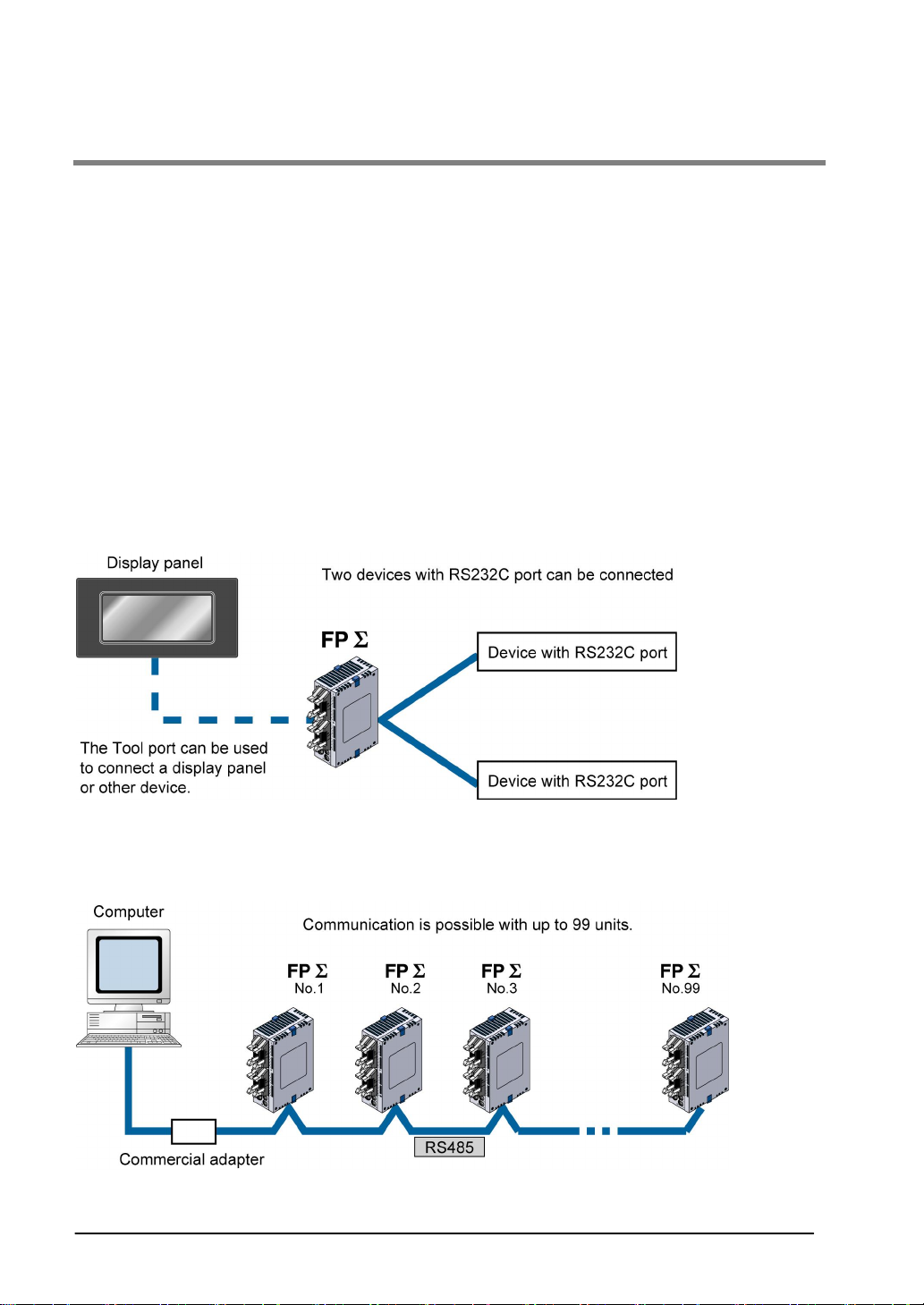
A full range of communication functions
Using the Tool port (RS232C) provided as a standard feature on the main unit, communication can be
carried out with a display panel or computer. Additionally, communication cassettes with RS232C and
RS485 interfaces are available as an option. Installing a 2-channel RS232C type communication
cassette in the FPΣ makes it possible to connect two devices with RS232C port. A full lineup of
communication functions means you can also work with 1:N communication (up to 99 units) and
PC(PLC) link function (up to 16 units).
Controlling two devices with RS232C port with one FPΣ
When using the 2-channel RS232C type communication cassette
1:N communication possible with up to 99 stations (units)
When using the 1-channel RS485 type communication cassette
When using the 1-channel RS485 and 1-channel RS232C in combination
1-2
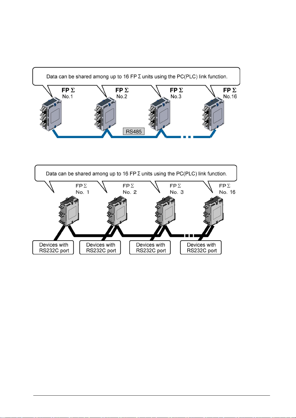
Data can be share among the various PLCs using the PC(PLC) link function
When using the 1-channel RS485 type communication cassette
When using the 1-channel RS485 and 1-channel RS232C combination type
PC(PLC) link function (up to 16 units) or 1:N communication (up to 99 units) with RS232C devices
When using the 1-channel RS485 and 1-channel RS232C in combination
Analog control supported
An analog potentionmeter (volume dial) is provided as a standard feature. This can be used in
applications such as analog timers, without using the programming tools. An analog unit is also available
as the intelligent unit.
Type with thermister input function
For the units of which part numbers or product numbers end in “TM”, the leader line which enables the
thermister input is equipped instead of an analog potetionmeter. The change of the resistance value of
the thermister can be taken in as an analog value.
(The thermister of which resistance value is from 200 to 75 kΩ can be used.)
Calender timer function can be added
Optional backup battery enables the calender timer function.
1-3
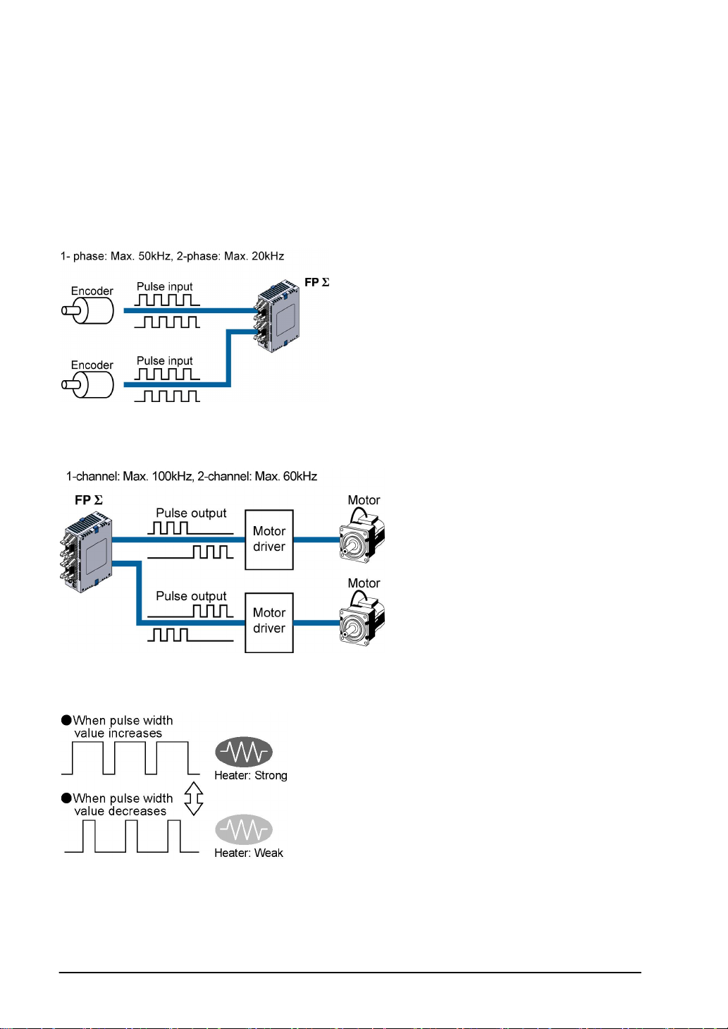
Positioning control supported through high-speed counter and pulse output
A high-speed counter and pulse output functions are provided as standard features. The pulse output
function supports frequencies of up to 100kHz, enabling positioning control using a stepping motor or
servo motor.
Measurement using high-speed counter supported
Increment input mode, decrement input mode, 2-phase input mode, individual input mode, and direction
discrimination mode are supported.
Positioning control based on pulse output supported
Pulse/direction and clockwise/counter –clockwise output are supported.
Heater control based on PWM output function supported
The pulse output at any duty ratio can be picked up with special instruction.
1-4

Security functions have been enhanced.
1. Upload protection. (Enables not to upload programs.)
2. 8-digit alphameric password
3. 4-digit numeric password
Easy temperature control instruction has been added.
It enables to perform the operation easily like a temperature control device.
Single-line PID instruction has been added.
Three-port general purpose serial communication
The tool port also supports the general-purpose serial communication.
Modbus RTU master unit and slave units
Communication with a temperature control device, inverter or measuring insturments can be performed
with simple programs using the FPΣ as a master unit.
Communication with the exsiting network can be performed using the FPΣ as slave units.
MEWTOCOL master unit
Programs for the MEWTOCOL communication master unit can be easily created.
Rewrite function during RUN
Programs can be changed during RUN up to 512k steps.
1-5

1.2 Unit Types
1.2.1 FPΣ Control Unit
12k type
Name Number of I/O points Part No. Product No.
Input: 16 points/Transistor output: 16
points NPN
Input: 16 points/Transistor output: 16
FPΣ Control unit
FPΣ Control unit
With thermister input
function
Note) The FPΣ expansion I/O unit cannot be added to FPG-C32T nor FPG-C32TTM FPΣ control unit.
32k type
Name Number of I/O points Part No. Product No.
FPΣ Control unit
(High capacity type)
Program capacity: 32k
FPΣ Control unit
(High capacity type)
Program capacity: 32k
With thermister input
function
Note) The FPΣ expansion I/O unit cannot be added to FPG-C32TH nor FPG-C32THTM FPΣ control unit.
points NPN
Input: 16 points/Transistor output: 12
points PNP
Input: 16 points/Relay output: 8 points FPG-C24R2 AFPG2423
Input: 16 points/Transistor output: 16
points NPN
Input: 16 points/Transistor output: 16
points NPN
Input: 16 points/Transistor output: 12
points PNP
Input: 16 points/Relay output: 8 points FPG-C24R2TM AFPG2423TM
Input: 16 points/Transistor output: 16
points NPN
Input: 16 points/Transistor output: 16
points NPN
Input: 16 points/Transistor output: 12
points PNP
Input: 16 points/Relay output: 8 points FPG-C24R2H AFPG2423H
Input: 16 points/Transistor output: 16
points NPN
Input: 16 points/Transistor output: 16
points NPN
Input: 16 points/Transistor output: 12
points PNP
Input: 16 points/Relay output: 8 points
FPG-C32T AFPG2543
FPG-C32T2 AFPG2643
FPG-C28P2 AFPG2653
FPG-C32TTM AFPG2543TM
FPG-C32T2TM AFPG2643TM
FPG-C28P2TM AFPG2653TM
FPG-C32TH AFPG2543H
FPG-C32T2H AFPG2643H
FPG-C28P2H AFPG2653H
FPGC32THTM
FPGC32T2HTM
FPGC28P2HTM
FPGC24R2HTM
AFPG2543HTM
AFPG2643HTM
AFPG2653HTM
AFPG2423HTM
1-6

1.2.2 FPΣ Expansion Unit
Name Specifications Part No. Product No. Manual
Input: 32 points/Transistor
FPΣ Expansion
I/O unit
FPΣ
Positioning unit
FPΣ Expansion
data memory unit
FPΣ CC-Link
slave unit
FPΣ S-LINK unit
Note) The FPΣ expansion I/O unit cannot be added to FPG-C32T nor FPG-C32TTM FPΣ control unit.
output: 32 points NPN
Input: 32 points/Transistor
output: 32 points PNP
Transistor output: 1-axis type FPG-PP11 AFPG430
Transistor output: 2-axis type FPG-PP21 AFPG431
Line driver output: 1-axis type FPG-PP12 AFPG432
Line driver output: 2-axis type FPG-PP22 AFPG433
256 kbyte FPG-EM1 AFPG201
Number of points of
exchanged data with CCLink master station
Max. 224 points (Input: 112
points, output: 112 point)
Writing max. 16-word data
Reading 4-word data
128 input/output points using
S-LINK
FPG-XY64D2T AFPG3467
FPG-XY64D2P AFPG3567
FPG-CCLS AFPG7943
FPG-SL AFPG780
This
manual
ARCT1F
365E
This
manual
ARCT1F
380E
ARCT1F
403E
1-7

1.2.3 FP0 Expansion Unit
The FP0 series expansion I/O unit and intelligent unit can be used on FPΣ.
Expample: <FP0 User’s manual ARCT1F251>
1.2.4 Communication Cassette
Name Description Part No. Product No.
FPΣ Communication
cassette 1-channel
RS232C type
FPΣ Communication
cassette 2-channel
RS232C type
FPΣ Communication
cassette 1-channel
RS485 type
FPΣ Communication
cassette 1-channel
RS485 type & 1channel RS232C type
This communication cassette is a 1-channel
unit with a five-wire RS232C port. RS/CS
control is possible.
This communication cassette is a 2-channel
unit with a three-wire RS232C port.
Communication with two external devices is
possible.
This communication cassette is a 1-channel
unit with a two-wire RS485 port. FPG-COM3 AFPG803
This communication cassette is a 1-channel
unit with a two-wire RS485 port and a 1channel unit with a three-wire RS232C port.
FPG-COM1 AFPG801
FPG-COM2 AFPG802
FPG-COM4 AFPG806
1.2.5 Related parts
Name Description Product No.
FPΣ battery Necessary for the backup of data registers, etc
or for using the calender function
With one-sided wire-press socket
MIL one-sided socket type
FPΣ power supply cable Maintenance parts (Packed with
FP0 terminal block socket (2 pcs) Maintenance parts (Packed with the relay output
FP2 terminal block socket (2 pcs) Maintenance parts (Packed with the Expansion
FP0 Wire-press shocket (2 pcs) Maintenance parts (Packed with the Tr type) AFP0807
FP0 mounting plate (slim type) (10
pcs)
FP0 mounting plate (slim 30 type)
(10 pcs)
FP0 mounting plate (flat type) Mounting plate to mount the control unit on a
Terminal driver Necessary for the wiring of PHOENIX terminal AFP0806
AWG #22 0.3 mm
the control unit)
type)
I/O unit)
Mounting plate to mount FP0 expansion unit on
a panel vertically
Mounting plate to mount FPΣ control unit, FPΣ
expansion unit on a panel vertically
panel horizontally
2
, 2 pcs
Cable
length: 1 m
Cable
length: 3 m
Cable
length: 1 m
AFPG804
AFP0521 10-wire I/O cable
AFP0523
AFPG805
AFP0802
AFP2801
AFP0803
AFP0811
AFP0804
1-8
1.3 Restrictions on Unit Combinations
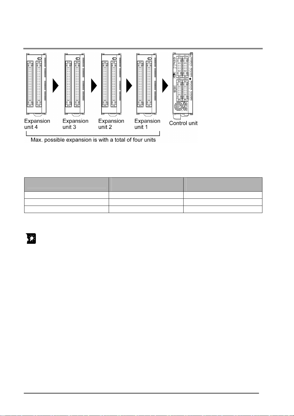
1.3.1 Restrictions on FP0 Expansion Unit
Up to three expansion units can be added on the right of the FPΣ, these expansion units being either
expansion units or intelligent units from the earlier FP0 series, or a combination of the two.
A combination of relay output types and transistor output types is also possible.
Controllable I/O points
Type os control unit
FPG-C32 32 ponts Max. 128 points
FPG-C28 28 points Max. 124 points
FPG-C24 24 points Max. 120 points
Note1) This is the number of points when combining with the transistor type FP0 expansion unit.
Number of I/O points when
using control unit
Number of I/O points when
using FP0 expansion unit
Note1)
Note:
• Install the FP0 thermocouple unit on the right side of all other expansion units. If it is installed on the
left side, the total precision will deteriorate.
• Install the FP0 CC-Link slave unit on the right side of the other expansion units. There is no expansion
connector on the right side.
1-9
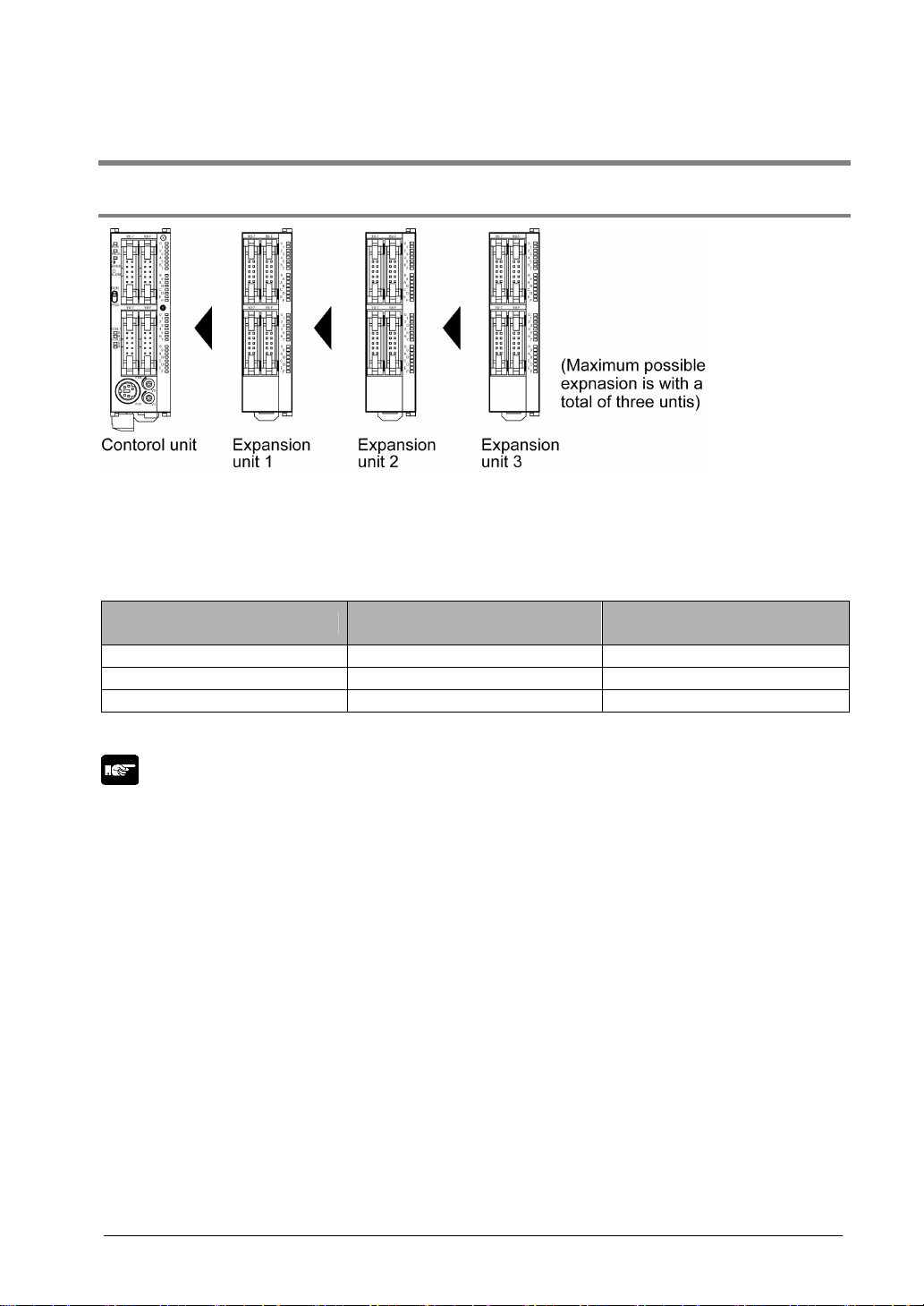
1.3.2 Restrictions on FPΣ Expansion Unit
Up to four dedicated FPΣ expansion units can be added on the left of the FPΣ.
The 64 points type expansion unit consists of 32 input points and 32 transistor NPN output points.
Controllable I/O points
Type os control unit
FPG-C32
Note1)
32 ponts Max. 128 points
Number of I/O points when
using control unit
FPG-C28 28 points Max. 124 points
Number of I/O points when
using FPΣ expansion unit
Note2)
Note2)
FPG-C24 24 points Max. 120 points
Note1) The FPΣ cannot be used for FPG-C32T, FPG-C32TTM, FPG-C32TH nor FPG-C32THTM.
Note2) This is the number of points when combining with the 64-point type FPΣ expansion unit.
Key Point:
If using FP0 expansion units and FPΣ expansion units in combination, the number of input and output
points can be expanded to a maximum of 384 points for FPG-C32T2 and FPG-C32T2TM.
1-10
1.4 Programming Tools
1.4.1 Tools Needed for Programming
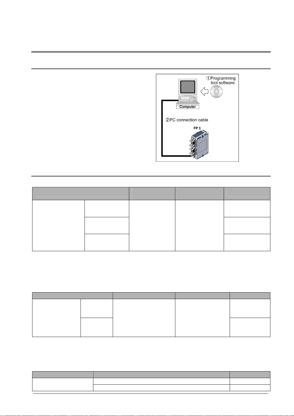
1. Programming tool software
• The tool software can also be used with the FP
series.
• “FPWIN Pro Ver.5” or “FPWIN GR Ver.2”
Windows sorware is used with FPΣ.
FPWIN GR Ver.1x, NPST-GR and FP
Programmer cannot be used.
2. PC connection cable
• The connection cable for DOS/V machine is
available.
1.4.2 Software Environment and Suitable Cable
Standard ladder diagram tool software FPWIN-GR Ver.2
Type of software
Full type AFPS10520
FPWIN GR Ver.2
English-language
Small type AFPS11520
menu
Upgrade version
Note1) Ver.1.1 must be installed to install the upgrade version.
Note2) Ver.2.0 can be upgraded to Ver. 2.1 or later free of charge at our web site
(
Note3) The small type can be used only for each series of FP-e, FPΣ, FP0, FP-X, FP1 and FP-M.
Conforms to IEC61131-3 programming tool software FPWIN-Pro Ver.5
FPWIN Pro Ver.5
Englishlanguage menu
Note1) Ver.5.0 can be upgraded to Ver. 5.1 or later free of charge at our web site
(
Note2) The small type can be used only for each series of FP-e, FPΣ, FP0, FP-X, FP1 and FP-M.
Type of computer and suitable cable
D-sub 9-pin
1-11
http://www.nais-j.com/plc/).
Type of software OS (Operating system) Hard disk capacity Product No.
Windows®95 (OSR 2 or
Full type AFPS50550
Small type
http://www.nais-j.com/plc/).
Connector Specifications Product No.
D-sub 9-pin female-Mini DIN round 5-pin AFC8503
D-sub 0-pin female-Mini DIN round 5-pin straight type AFC8503S
later)/ Windows®98/
Windows®Me/
WindowsNT® (Ver. 4 or
later)/ Windows®2000/
Windows®XP
OS (Operating
system)
Windows®95
(OSR 2 or later)/
Windows®98/
Windows®Me/
WindowsNT®
(Ver. 4 or later)/
Windows®2000/
Windows®XP
Hard disk
capacity
40MB or more
100MB or more
Product No.
AFPS10520R
AFPS51550

1-12

Chapter 2
Specifications and Functions of the Unit
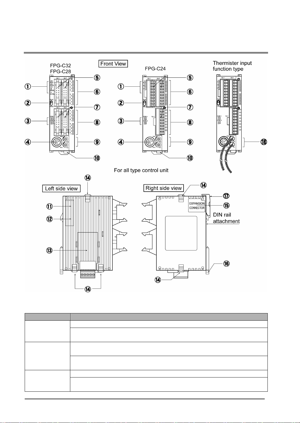
2.1 Parts and Functions
① Status indicator LEDs
These LEDs display the current mode of operation or the occurrence of an error.
LED LED and operation status
Lights when in the RUN mode and indicates that the program is being executed.
RUN (green)
PROG. (green)
ERROR/ALARM
(red)
2-2
It flashes during forced input/output. (The RUN and PROG. LEDs flash
alternately.)
Lights when in the PROG. Mode and indicates that operation has stopped.
Lights when in the PROG. Mode during forced input/output.
It flashes during forced input/output. (The RUN and PROG. LEDs flash
alternately.)
Flashes when an error is detected during the self-diagnostic function. (ERROR)
Lights if a hardware error occurs, or if oepration slows because of the program,
and the watchdog timer is activated. (ALARM)
 Loading...