

Panasonic FP7 CPU Unit User Manual

PROGRAMMABLE CONTROLLER
FP7 CPU Unit
User's Manual
LAN port communication
WUME-FP7LAN-01
2013.3
panasonic.net/id/pidsx/global

Safety Precautions
Observe the following notices to ensure personal safety or to prevent accidents.
To ensure that you use this product correctly, read this User’s Manual thoroughly before use.
Make sure that you fully understand the product and information on safety.
This manual uses two safety flags to indicate different levels of danger.
WARNING
If critical situations that could lead to user’s death or serious injury is assumed by
mishandling of the product.
-Always take precautions to ensure the overall safety of your system, so that the whole
system remains safe in the event of failure of this product or other external factor.
-Do not use this product in areas with inflammable gas. It could lead to an explosion.
-Exposing this product to excessive heat or open flames could cause damage to the lithium
battery or other electronic parts.
CAUTION
If critical situations that could lead to user’s injury or only property damage is
assumed by mishandling of the product.
-To prevent excessive exothermic heat or smoke generation, use this product at the values
less than the maximum of the characteristics and performance that are assured in these
specifications.
-Do not dismantle or remodel the product. It could cause excessive exothermic heat or smoke
generation.
-Do not touch the terminal while turning on electricity. It could lead to an electric shock.
-Use the external devices to function the emergency stop and interlock circuit.
-Connect the wires or connectors securely.
The loose connection could cause excessive exothermic heat or smoke generation.
-Do not allow foreign matters such as liquid, flammable materials, metals to go into the inside
of the product. It could cause excessive exothermic heat or smoke generation.
-Do not undertake construction (such as connection and disconnection) while the power
supply is on. It could lead to an electric shock.
Copyright / Trademarks
-This manual and its contents are copyrighted.
-You may not copy this manual, in whole or part, without written consent of
Industrial Devices SUNX Co., Ltd.
-Windows is a registered trademark of Microsoft Corporation in the United States and other
countries.
-Ethernet is a registered trademark of Fuji Xerox Co., Ltd. and Xerox Corp.
-All other company names and product names are trademarks or registered trademarks of
their respective owners.
Panasonic
PLC_ORG_ET

Introduction
use
Thank you for buying a Panasonic product. Before you use the product, please carefully read
the installation instructions and the users manual, and understand their contents in detail to
use the product properly.
Types of Manual
• There are different types of users manual for the FP7 series, as listed below. Please refer to
a relevant manual for the unit and purpose of your use.
• The manuals can be downloaded on our website:
http://industrial.panasonic.com/ac/e/dl_center/manual/
Unit name or purpose of
Manual name Manual code
.
FP7 Power Supply Unit
FP7 CPU Unit
Instructions for Built-in
COM Port
FP7 Extension
(Communication)
Cassette
Instructions for Built-in
LAN Port
FP7 Digital Input/Output Unit FP7 Digital Input/Output Unit Users Manual WUME-FP7DIO
FP7 Analog Input Unit FP7 Analog Input Unit Users Manual WUME-FP7AIH
FP7 Analog Output Unit FP7 Analog Output Unit Users Manual WUME-FP7AOH
FP7 Positioning Unit FP7 Positioning Unit Users Manual WUME-FP7POSP
PHLS System PHLS System Users Manual WUME-PHLS
Programming Software
FPWIN GR7
FP7 CPU Unit Users Manual
(Hardware)
FP7 CPU Unit Users Manual
(COM Port Communication)
FP7 CPU Unit Users Manual
(LAN Port Communication)
FPWIN GR7 Introduction Guidance WUME-FPWINGR7
WUME-FP7CPUH
WUME- FP7COM
WUME-FP7LAN

Table of Contents
Table of Contents
1. Communication Functions of CPU Unit ............................ 1-1
1.1 Communication Ports of CPU Unit ......................................................... 1-2
1.1.1 Types and Purposes of Communication Ports ........................................ 1-2
1.1.2 LAN Port Specifications ........................................................................... 1-3
1.2 Functions of LAN Port ............................................................................ 1-4
1.2.1 Communication Functions of FP7 CPU Unit ........................................... 1-4
1.2.2 System Connection ................................................................................. 1-4
1.2.3 User Connection ...................................................................................... 1-5
1.3 Overview of Communication Functions .................................................. 1-6
1.3.1 MEWTOCOL-DAT Master/Slave Communication (Binary
Communication) ...................................................................................... 1-6
1.3.2 MEWTOCOL-COM Master/Slave Communication (ASCII
Communication) ...................................................................................... 1-7
1.3.3 MODBUS TCP Master/Slave Communication ........................................ 1-8
1.3.4 General-Purpose Communication ........................................................... 1-9
1.4 Terms ................................................................................................... 1-10
2. Installation and Wiring ........................................................ 2-1
2.1 Installation Environment and Wiring for LAN Ports ................................ 2-2
2.1.1 Before Installation and Wiring ................................................................. 2-2
2.1.2 Installation Environment and Noise Control Measures ........................... 2-2
2.2 Wiring the LAN Port ................................................................................ 2-3
2.3 Noise Control Measures ......................................................................... 2-4
2.3.1 Guidelines to Noise Generation .............................................................. 2-4
2.3.2 Taking Corrective Measures through the Application ............................. 2-4
ii

Table of Contents
3. Configuration ....................................................................... 3-1
3.1 Procedure for Setting Communication Conditions .................................. 3-2
3.1.1 Setup Procedure ..................................................................................... 3-2
3.2 Setting Basic Communication Information .............................................. 3-3
3.2.1 List of Setting Items ................................................................................. 3-3
3.2.2 Setting Each Timer Value And Timeout Value ........................................ 3-4
3.3 Settings for SNTP server ........................................................................ 3-5
3.4 Settings for FTP server ........................................................................... 3-6
3.5 Setting of System Connection ................................................................ 3-7
3.5.1 List of Setting Items ................................................................................. 3-7
3.5.2 Setting on the Programming Tool Side ................................................... 3-9
3.6 Setting of User Connection ................................................................... 3-10
3.6.1 List of Setting Items ............................................................................... 3-10
3.6.2 Specifying Port Number ........................................................................ 3-12
4. Setting and Operation of User Connection ....................... 4-1
4.1 Configuration Concerning Open Process ............................................... 4-2
4.1.1 Connection of the FP7 CPU Unit ............................................................ 4-2
4.1.2 Specifying Use of Connection ................................................................. 4-2
4.1.3 Open Method (Server/Client) .................................................................. 4-2
4.1.4 Open Method (Auto/Manual) ................................................................... 4-2
4.1.5 Instructions for Specifying Connection Conditions.................................. 4-3
4.2 Communication Processing .................................................................... 4-4
4.2.1 Communication Operation ...................................................................... 4-4
4.3 Input/Output Signals Used for Communication ....................................... 4-5
4.3.1 I/O Allocation ........................................................................................... 4-5
iii

Table of Contents
5. MEWTOCOL Master/Slave Communication ...................... 5-1
5.1 Types of MEWTOCOL Communication ................................................. 5-2
5.1.1 MEWTOCOL-DAT (Binary Communication) ........................................... 5-2
5.1.2 MEWTOCOL-COM (ASCII Communication) ........................................... 5-2
5.2 List of MEWTOCOL Supporting Commands .......................................... 5-3
5.2.1 MEWTOCOL-DAT ................................................................................... 5-3
5.2.2 MEWTOCOL-COM .................................................................................. 5-3
5.2.3 MEWTOCOL7-COM ................................................................................ 5-3
5.3 MEWTOCOL Master Communication (RECV) ....................................... 5-4
5.3.1 Read Data From an External Device ...................................................... 5-4
5.3.2 RECV Command (When MEWTOCOL is Used)..................................... 5-6
5.4 MEWTOCOL Master Communication (SEND) ....................................... 5-7
5.4.1 Write Data into an External Device ......................................................... 5-7
5.4.2 SEND Command (When MEWTOCOL is Used)..................................... 5-9
6. MODBUS TCP Master/Slave Communication ................... 6-1
6.1 MODBUS TCP Format ........................................................................... 6-2
6.1.1 MODBUS TCP ........................................................................................ 6-2
6.2 List of MODBUS TCP Supported Commands ........................................ 6-3
6.2.1 List of MODBUS Function Codes ............................................................ 6-3
6.3 MODBUS TCP Master Communication (RECV) .................................... 6-4
6.3.1 Read Data from an External Device ........................................................ 6-4
6.3.2 RECV Command (MODBUS Function Code Specified Type) ................ 6-7
6.3.3 RECV Command (MODBUS Function Code Unspecified Type) ............ 6-8
6.4 MODBUS TCP Master Communication (SEND) .................................... 6-9
6.4.1 Write Data into an External Device ......................................................... 6-9
iv
6.4.2 SEND Command (MODBUS Function Code Specified Type) .............. 6-11
6.4.3 SEND Command (MODBUS Function Code Unspecified Type) .......... 6-12

Table of Contents
7. General-Purpose Communication ..................................... 7-1
7.1 Operation of General-Purpose Communication ...................................... 7-2
7.1.1 Read Data from an External Device ....................................................... 7-2
7.1.2 Write Data into an External Device ......................................................... 7-2
7.1.3 Sending Format in General-Purpose Communication ............................ 7-3
7.2 Sending Operation .................................................................................. 7-4
7.2.1 Overview of Sending Operation .............................................................. 7-4
7.2.2 Contents of Sent Data ............................................................................. 7-6
7.2.3 GPSEND (General-Purpose Communication Sending Command) ........ 7-7
7.3 Receiving Operation ............................................................................... 7-8
7.3.1 Overview of Receiving Operation ............................................................ 7-8
7.3.2 Contents of Received Data ................................................................... 7-10
7.3.3 GPRECV (General-Purpose Communication Receiving Command) ... 7-11
8. Specifications ...................................................................... 8-1
8.1 Specifications of CPU Unit LAN Port Communication Function ............. 8-2
8.2 MEWTOCOL-DAT Format ...................................................................... 8-3
8.2.1 MEWTOCOL-DAT Command Format in LAN Command Format .......... 8-3
8.2.2 MEWTOCOL-DAT Command/Response Format ................................... 8-4
8.3 MEWTOCOL-COM Format ..................................................................... 8-6
8.3.1 MEWTOCOL-COM Command Format in LAN Communication ............. 8-6
8.3.2 MEWTOCOL-COM Command Format ................................................... 8-7
8.3.3 MEWTOCOL-COM Response Format .................................................... 8-9
8.4 MEWTOCOL7-COM Format ................................................................. 8-11
8.4.1 MEWTOCOL7-COM Command Format ............................................... 8-11
8.4.2 MEWTOCOL7 Response Format ......................................................... 8-13
v

Table of Contents
vi

1
Communication Functions of
CPU Unit
Communication Functions of CPU Unit
REFERENCE
1.1 Communication Ports of CPU Unit
1.1.1 Types and Purposes of Communication Ports
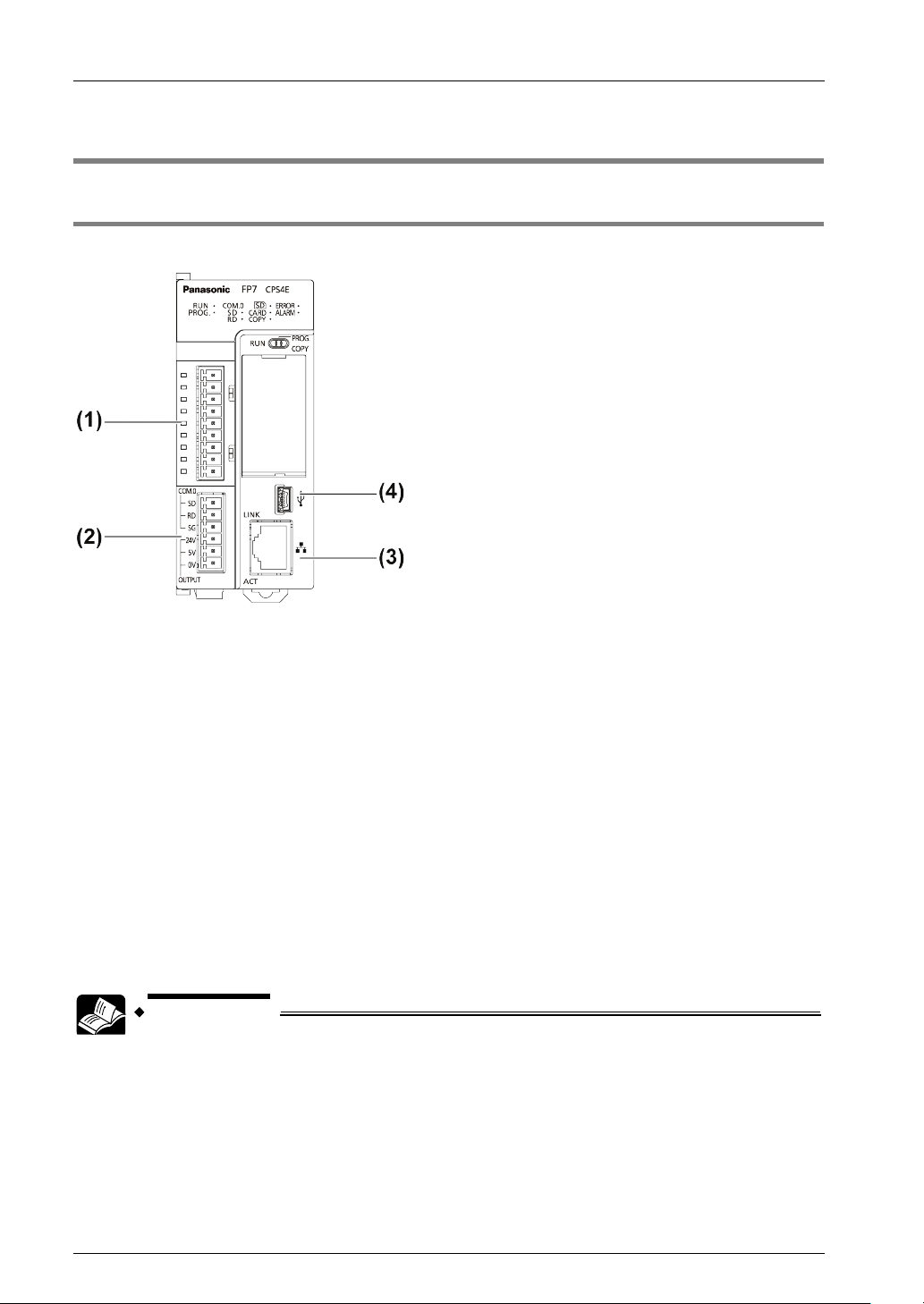
Communication ports of CPU unit
Functions of Ports
(1) COM1 and COM2 Ports
Attach a separately sold communication cassette to use these ports. You can select from five
types of communication cassettes.
(2) COM0 Port
This is an RS-232C port that is equipped to a standard model of CPU unit. It is equipped with
power supply terminals (5V DC and 24V DC) to which a GT series display can be connected.
(3) LAN Port
This is equipped to a standard model of CPU unit. It is used for connection to Ethernet. It can
also be connected with a programming tool. The MAC address is printed on the side of the
unit. It supports the Ethernet communication interfaces 100BASE-TX and 10BASE-T.
100BASE-TX and 10BASE-T are automatically switched by the auto negotiation function.
(4) USB Port
This is equipped to a standard model of CPU unit. This is used when connecting tool software.
• For communication using the COM port, please see the CPU Unit Users
Manual (COM Port Communication).
1-2

1.1 Communication Ports of CPU Unit
1.1.2 LAN Port Specifications
100BASE-TX / 10BASE-T connector (RJ45)
This connector connects the ET-LAN Unit and the Hub in Ethernet (100BASE-TX, 10BASE-T)
and UTP Cable.
Pin no. Signal name
1 TX+
2 TX-
3 RX+
4 Not used
5 Not used
6 RX-
7 Not used
8 Not used
Functions of LED lamps
(1) LINK
Turns on when connection is established between the FP7 CPU unit and a device on Ethernet.
(2) ACK
Flashes when some communication is in progress with a connected device (e.g.
sending/receiving a command or response).
1-3
Communication Functions of CPU Unit
1.2 Functions of LAN Port
1.2.1 Communication Functions of FP7 CPU Unit
Configuration chart
Communication functions of FP7 CPU Unit
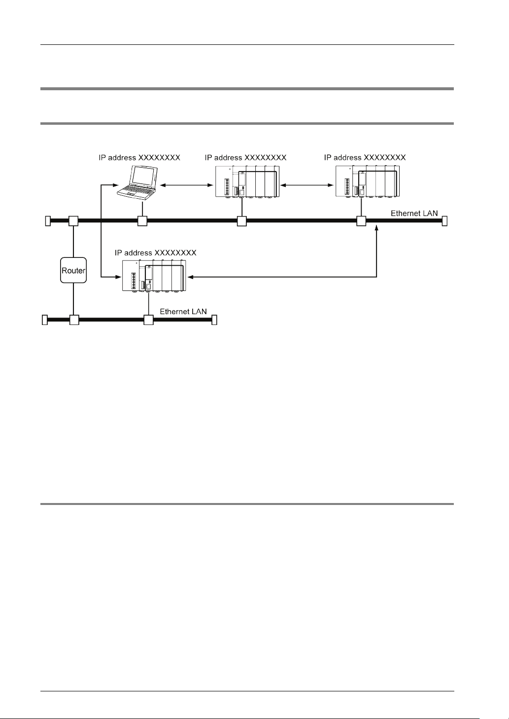
• The FP7 CPU Unit can open a virtual communication line with an Ethernet-supporting device
connected to LAN, and send/receive data.
• IP address of the FP7 CPU unit, protocol (TCP/UDP), connection method with devices, port
numbers, etc. should be specified in the configuration menu of the programming tool FPWIN
GR7.
• In master communication commands SEND/RECV, messages in accordance with the
protocol are automatically generated by PLC. In the user program, reading and writing can
be done simply by specifying the station no. and memory address and executing commands.
• Communication functions can be selected depending on the partner device to be connected.
1.2.2 System Connection
Functions of system connection
• System connection is used when using a programming tool via LAN port.
• Four connections are available per CPU unit.
1-4
1.2 Functions of LAN Port
IP XXXXXX
FP7 CPU
1
Port
8000
External
device
IP XXXX
Port XXXX
2
Port
8001
16
Port
8015
Ethernet LAN
Select a desired communication
method for each connection
IP XXXX
Port XXXX
IP XXXX
Port XXXX
FP7 CPU
1
Port
8000
External
device
2
Port
8001
16
Port
8015
Ethernet LAN
Select a desired communication
method for each connection
IP XXXXXX
Port
XXXX
Port
XXXX
Port
XXXX
IP XXXXXX
MEWTOCOL-COM
Master
Slave
Master
Slave
Master
Slave
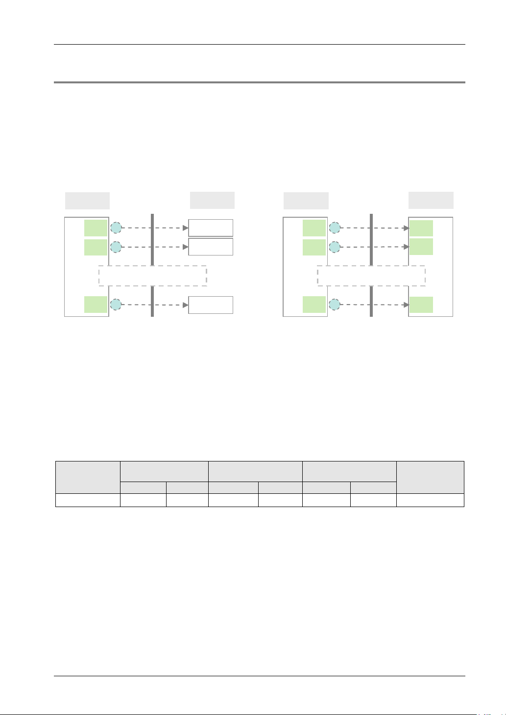
1.2.3 User Connection
Functions of user connection
• The FP7 CPU Unit can open virtual communication lines for up to 16 connections with
Ethernet-supporting devices connected to LAN, and send/receive data.
• It can open multiple connections between the FP7 CPU unit and multiple nodes or a single
node, and execute communication.
• Operation mode, open method, protocol, etc. can be selected for each connection.
Note) Circled numbers in the figure above indicate examples of allocation of connection numbers.
Connection operation
• Connection is opened from either the FP7 CPU unit side or the external device side.
• The open method should be selected from server connection (unspecified partner), server
connection (specified partner), and client connection, in the configuration menu of FPWIN
GR7.
• Once connection is established, communication by a user program becomes possible in
accordance with the operation mode.
Supported operation mode
Communication
MEWTOCOL-DAT
MEWTOCOL7-COM
port
LAN port ●
● ○ (Note)
(Note) MEWTOCOL7-COM does not support master functions.
MODBUS-TCP
● ● ● ●
Generalpurpose
communication
1-5

Communication Functions of CPU Unit
FP7 CPU
Our PLC supporting
MEWTOCOL-DAT
Ethernet LAN
IP XXXXXX
IP XXXXXX
Send/receive data using
MEWTOCOL
-DAT
Command
Master
communication
Slave
communication
Response
Command
Response
KEY POINTS
1.3 Overview of Communication Functions
1.3.1 MEWTOCOL-DAT Master/Slave Communication (Binary Communication)
Overview of function
• Execute communication using MEWTOCOL-DAT, a communication protocol usd by our PLC.
• One of the PLC has the sending right, and executes communication by sending commands
to PLCs that support MEWTOCOL-DAT, and receiving responses.
• The slave-side PLC responds automatically, so no program concerning communication is
necessary.
• Also on the master-side PLC, messages in accordance with the protocol are automatically
generated by PLC. In the user program, reading and writing can be done between PLCs
simply by specifying the station no. and memory address and executing SEND/RECV
commands.
• This is suitable for sending/receiving data between PLCs, because the data size that can be
transmitted in a single communication is larger, and the transmission format is simpler and
shorter, than the MEWTOCOL-COM communication (ASCII communication).
• The data size that can be sent or received in a single communication is up to 2038 words for
register transmission and 1 bit for bit transmission.
(Note) In the case of connection with our PLC FP2 ET-LAN unit, the maximum size is 1020 words.
Purpose of MEWTOCOL-DAT communication
This is used for sending data with our PLC that supports MEWTOCOL-DAT via Ethernet.
• Programmable controller FP series
• When MEWTOCOL-DAT master/slave communication is used, select
"TCP/IP" for the communication protocol in order to guarantee the reliability
of communication.
1-6

1.3 Overview of Communication Functions
FP7 CPU
Device supporting
MEWTOCOL
-COM
Ethernet LAN
IP XXXXXX
IP XXXXXX
Send/receive data using
MEWTOCOL-COM
Command
Master
communication
Slave
communication
Response
Command
Response
1.3.2 MEWTOCOL-COM Master/Slave Communication (ASCII Communication)
Overview of function
•
Execute communication using MEWTOCOL-COM, a communication protocol used by our PLC.
• One of the device has the sending right, and executes communication by sending
commands to devices that support MEWTOCOL-COM, and receiving responses.
• The slave-side PLC responds automatically, so no program concerning communication is
necessary.
• Also on the master-side PLC, messages in accordance with the protocol are automatically
generated by PLC. In the user program, reading and writing can be done simply by
specifying the station no. and memory address and executing SEND/RECV commands.
• Because MEWTOCOL-COM communication is on an ASCII basis, it is suitable for
sending/receiving text data.
• The data size that can be sent or received in a single communication is up to 507 words for
register transmission and 1 bit for bit transmission.
Applications of MEWTOCOL-COM communication
This is used for sending text data between our devices that support MEWTOCOL-COM via
Ethernet. This method can also be used for connecting a programming tool.
• Programmable controller FP series
1-7

Communication Functions of CPU Unit
FP7 CPU
MODBUS-TCP
supporting device
Ethernet LAN
IP XXXXXX
IP XXXXXX
Send/receive data using
MODBUS-TCP
Command
Master
communication
Slave
communication
Response
Command
Response
1.3.3 MODBUS TCP Master/Slave Communication
Overview of function
• This is used for communicating with other devices that support the MODBUS TCP protocol.
• In master communication, communication is performed when the master unit sends
instructions (command messages) to slave units and the slave unit returns responses
(response messages) according to the instructions. Messages in accordance with the
protocol are automatically generated by PLC. In the user program, reading and writing can
be done simply by specifying the station no. and memory address and executing
SEND/RECV commands.
• Slave communication is performed when the higher device connected to PLC has the
sending right, and sends commands, and PLC returns responses. In slave communication,
PLC responds automatically, so no program concerning communication is necessary on the
PLC side.
• The data size that can be sent or received in a single communication is up to 127 words for
register transmission and 2040 bit for bit transmission.
1-8

1.3 Overview of Communication Functions
FP7 CPU External device
Ethernet LAN
IP XXXXXX
IP XXXXXX
Send/receive message/data
Message/data
Send
Receive
Operation
memory
Message/data
1.3.4 General-Purpose Communication
Overview of function
• General-purpose communication is used when PLC executes communication in accordance
with the command specifications of the partner device.
• Formulation and sending of command messages to the partner device, and reception
processing of responses from the partner device, are performed by the user program.
Sending/receiving of data with an external device is executed via given operation memory
(e.g. data register).
• Data are sent by setting message/data in a given data register in accordance with the
partner device, and executing GPSEND command.
• Data received from the partner device are temporarily saved in the buffer. Based on the
reception done flag, GPRECV command is executed and the received data are copied into a
given operation memory. The received data can be converted into numerical data, etc. as
necessary, by the user program.
• The data size that can be sent or received in a single communication is up to 16,372 bytes
per connection.
(Note 1) When a dedicated header is not attached, the size is up to 16,384 bytes.
(Note 2) In the case of connection with our PLC FP2 ET-LAN unit, the maximum size is 8,192 bytes.
Applications of general-purpose communication
This is used for communication with devices made by differing manufacturers that have
dedicated communication protocols.
1-9

Communication Functions of CPU Unit
FP7 CPU
(server
connection)
External device
(client connection)
IP XXXXXX
IP XXXXXX
Master
communication
Slave
communication
Ethernet
LAN
Command
Response
Command
Response
FP7 CPU
(client connection)
External device
(server
connection)
IP XXXXXX
IP XXXXXX
Master
communication
Slave
communication
Ethernet
LAN
Command
Response
Command
Response
Virtual line connection
from external device
Virtual line connection
from FP7 CPU
1.4 Terms
The following terms are used for settings on the software for connecting the FP7 CPU unit to
Ethernet LAN, and in the Users Manuals.
Server connection and client connection
• These indicate methods for connecting a virtual communication line between FP7 and an
external device.
• "Server connection" refers to a method to wait for connection from another client.
• "Client connection" refers to a method to connect a virtual communication line from the FP7
CPU unit to another external device port. Even if connection fails, repeated connection
attempts are made at a specified interval.
Master communication and slave communication
• These indicate methods for actually sending/receiving messages and data between FP7 and
an external device.
• In master communication, PLC sends commands and receives responses.
• In slave communication, commands are received from an external device, and responses
are returned.
• In a system using FP7, whether server connection or client connection is selected, once
connection is opened and a virtual communication line is connected, commands and
responses can be sent and received from both sides.
1-10

2
Installation and Wiring
Installation and Wiring
2.1 Installation Environment and Wiring for LAN Ports
2.1.1 Before Installation and Wiring
Noise resistance of Ethernet
The Ethernet is a network used in offices and buildings, where there is comparatively little
noise. It does not have a higher resistance to noise than ordinary FA application networks.
Caution is required when installing the hub, and when laying cables.
2.1.2 Installation Environment and Noise Control Measures
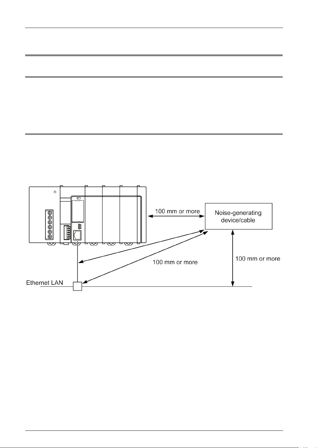
Measures that can be taken in the installation environm ent
• The CPU unit, transceiver, hub, and communication cables should be installed as far as
possible from high-voltage wires, high-voltage equipment, power lines, power equipment,
equipment that generates strong breaker surges, and the wiring for any of this equipment. At
least 100 mm of clearance should be allowed when installing the equipment.
• When a device must be installed or a cable must be laid near a noise-generating device for
special reasons, take measures such as:
• install a programmable controller and a hub within a metal panel,
• laying a communication cable inside a metal duct,
• attaching a ferrite core near the CPU unit on the communication cable,
etc.
• An alternative measure is to use an optical transceiver close to the noise-generating section
of the equipment and install an optical fiber to keep the noise from affecting nearby
equipment. (This is also effective as a lightning shield for outdoor wiring.)
• Metal panels and metal ducts should be grounded at a grounding resistance of 100 Ω or less.
Also, metal panels and metal ducts should be insulated so that they do not come in contact
with communication devices or cables.
2-2

2.2 Wiring the LAN Port
2.2 Wiring the LAN Port
Selection of UTP cables
• Use Category 5 UTP cable.
• It is recommended to use a UTP cable of 10 m or shorter, taking account of noise resistance.
• In an environment where noise may occur, attach a ferrite core near the CPU unit on the
UTP cable. It is also recommended to use a shielded cable.
• For installation of 100BASE-TX or 10BASE-T hub, laying of cables, etc.,
please consult a specialized construction company. If this construction
work is done incorrectly, it can adversely affect the entire network, and can
cause accidents.
2-3

Installation and Wiring
REFERENCE
2.3 Noise Control Measures
2.3.1 Guidelines to Noise Generation
• If any of the following are occurring, there is a danger that external noise is affecting the
communication circuit. Appropriate measures should be taken.
• Check to see if a communication error is occurring, in synchronization with the operation of
the device. If either of these is happening in synch with the operation of the device, take
whatever measures are necessary to suppress the generation of noise from the device side.
2.3.2 Taking Corrective Measures through the Application
Communication errors occurring in the unit can be minimized by taking the steps outlined
below. Corrective measures should also be taken on the computer side, such as increasing
the number of times that data is sent.
Increasing the number of times data is sent
• In the tool software FPWIN GR7, select built-in ET-LAN, adjust the "TCP ULP timeout value"
and "TCP re-transmission timer value" in "basic communication information" to increase the
number of times data is sent.
• The number of times data is sent is given in the following formula. "TCP ULP timeout value"
should be specified at an integral multiplication of "TCP re-transmission timer value". When
an integral multiplication cannot be given, round up the given decimal number. The max.
number of times data is sent is 12.
No. of times data is sent = "TCP ULP timeout value (packet existence duration)" / "TCP retransmission timer value"
• The above setting is invalid when UDP/IP is used. Use the application to send the
transmission again.
Increasing the timeout judgment time
When master communication commands (SEND/RECV) are executed, select "CPU
configuration" in the tool software FPWIN GR7, and increase the set value for "time settings:
timeout time for communication control commands" Default value is set at 10 seconds (set
value: 100)
• For configuration, please see 3.2.1 List of Setting Items.
2-4

3
Configuration
Configuration
PROCEDURE
3.1 Procedure for Setting Communication Conditions
3.1.1 Setup Procedure
• To use communication functions based on the LAN port, communication conditions must be
set.
• Settings should be performed by the programming tool FPWIN GR7.
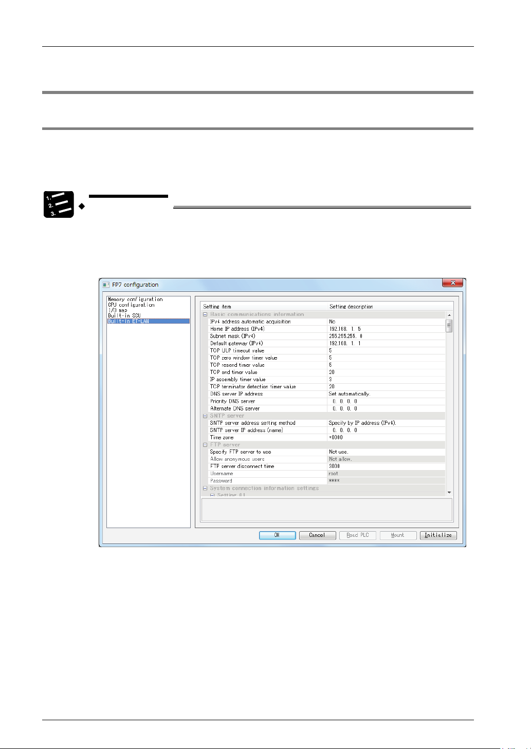
1. From the menu bar, select "Option" > "FP7 Configuration".
2. From the left pane, select "Built-in ET-LAN".
Setting items appear.
3. Specify conditions for each item under "Settings for Built-in ET-LAN", and
4. Select [File] > [Save As] in the menu bar.
3-2
press [OK] button.
The settings are registered in the project.

3.2 Setting Basic Communication Information
3.2 Setting Basic Communication Information
3.2.1 List of Setting Items
List of setting items (basic communication information)
Setting item Default Remark
Automatic getting of
IPv4 address
Own IP address (IPv4) 192.168.1.5
Subnet mask (IPv4) 255.255.255.0
Default gateway
(IPv4)
TCP ULP time-out value 5
TCP zero-window
timer value
TCP re-transmission
timer value
TCP closed timer value 20
IP assembling timer
value
TCP terminal detection
timer value
IP address of the DNS
server
Prioritized DNS server 0.0.0.0
Substitute DNS server 0.0.0.0
No
192.168.1.1
5
5
3
20
Set manually
This is valid as long as the network (subnetwork) mask field is
anything other than 0.
If the default router (gateway) IP address has been set,
communication will be carried out through the default router
(gateway) without an error occurring even f the class, network
address, or subnetwork address of the partner node differ from
those of the source node.
The network (subnetwork) address for the default router
(gateway) IP address must be identical to the network
(subnetwork) address for the source node IP address. If they are
different, an error will occur.
・0000 0000 H and FFFF FFFF H is regarded as an error.
Setting range: 0001 - FFFF: (by 100 ms)
With TCP, this specifies the time that a packet exists when data
transmission, etc. is carried out. "TCP ULP" should be specified
at an integral multiplication of "TCP re-transmission timer value".
When an integral multiplication cannot be given, round up the
given decimal number.
Setting range: 0001 - FFFF: (by 100 ms)
With TCP, this specifies the time until the receive window size
check packet is re-sent when the receive window size of the
other node becomes 0.
Setting range: 0001 - FFFF: (by 100 ms)
With TCP, this specifies the time until data is re-sent if ACK is
not sent by the other node, when data transmission, etc. is
carried out.
Setting range: 0001 - FFFF: (by 100 ms)
This specifies the time waited until open processing is carried
out when the same port is being re-opened, when TCP close
processing is done by the source node.
Setting range: 0001 - FFFF: (by 100 ms)
This specifies the time waited for the next portion of data when
data split by the IP is being received.
Setting range: 0001 - FFFF: (by 1 ms)
When divided TCP segments are received, specify the time for
monitoring the arrival of the following segment.
TCP reception is regarded as completed if no data are received
after the time as specified above has passed.
3-3

Configuration
KEY POINTS
3.2.2 Setting Each Timer Value And Timeout Value
For setting each timer value and timeout value, please refer to the description below.
Timer setting conditions in FPWIN GR7
Timer setting conditions in FPWIN GR7 are as follows.
• TCP closed timer value ≥ TCP ULP timeout value ≥ TCP re-transmission timer value
AND
• TCP zero window timer value ≥ IP assembly timer value
Setting the TCP ULP timeout value (packet existence duration) and
the TCP re-transmission timer value
When TCP/IP communication is being carried out, data is automatically re-sent the specified
number of times, as shown in the illustration below.
E.g. When TCP ULP: 30 seconds, TCP re-transmission timer value: 10 seconds
• Communication errors occurring in the unit can be minimized by increasing
• The max. number of times data is sent is 12.
• If UDP/IP is being used, re-sending is not carried out.
3-4
the number of re-transmission times. Corrective measures should also be
taken on the computer side, such as increasing the number of times that
data is sent.

3.3 Settings for SNTP server
3.3 Settings for SNTP server
These settings are required when the time is synchronized by SNTP while the calendar timer
function is being used.
List of setting items (SNTP server)
Setting item Default Setting method
SNTP server address Setting method
SNTP server IP address 0.0.0.0 Specify the setting for SNTP server (IP address / host name).
Time zone +0000
Specification
using IP
address (IPv4)
Select the setting for SNTP server
(specified by IP address (IPv4) / host name).
Setting unit: ± HHMM (HH: hour, MM: minute)
Setting range: +9999 to -9999
Specify a standard time zone in each region based on GMT.
3-5

Configuration
3.4 Settings for FTP server
Select this to use the FTP server function.
List of setting items (FTP server)
Setting item Default Setting method
Specifying use of FTP
server
Permission of anonymous
user
FTP server closing time 3000
User name root
Password root
No Select whether you will use the FTP server function.
No
If authentication by user account and password is not required,
select "Yes".
Setting unit: 100 ms
Setting range: 3,000 (0BB8H) to 429,496,729 (1999 9999 H)
Input the no-communication monitoring time during FTP
connection (unit: 100 ms). Connection is automatically cut off
when FTP no-communication exceeds the specified time.
3-6
 Loading...