

Page 1

PROGRAMMABLE CONTROLLER
FP7 Digital Input/Output Unit
User's Manual
WUME-FP7DIO-03
2020.10
panasonic.net/id/pidsx/global
Page 2

Safety Precautions
Observe the following notices to ensure personal safety or to prevent accidents.
To ensure that you use this product correctly, read this User’s Manual thoroughly before use.
Make sure that you fully understand the product and information on safety.
This manual uses two safety flags to indicate different levels of danger.
WARNING
If critical situations that could lead to user’s death or serious injury is assumed by
mishandling of the product.
-Always take precautions to ensure the overall safety of your system, so that the whole
system remains safe in the event of failure of this product or other external factor.
-Do not use this product in areas with inflammable gas. It could lead to an explosion.
-Exposing this product to excessive heat or open flames could cause damage to the lithium
battery or other electronic parts.
CAUTION
If critical situations that could lead to user’s injury or only property damage is
assumed by mishandling of the product.
-To prevent excessive exothermic heat or smoke generation, use this product at the values
less than the maximum of the characteristics and performance that are assured in these
specifications.
-Do not dismantle or remodel the product. It could cause excessive exothermic heat or smoke
generation.
-Do not touch the terminal while turning on electricity. It could lead to an electric shock.
-Use the external devices to function the emergency stop and interlock circuit.
-Connect the wires or connectors securely.
The loose connection could cause excessive exothermic heat or smoke generat ion.
-Do not allow foreign matters such as liquid, flammable materials, metals to go into the inside
of the product. It could cause excessive exothermic heat or smoke generation.
-Do not undertake construction (such as connection and disconnection) while the power
supply is on. It could lead to an electric shock.
Copyright / Trademarks
-This manual and its contents are copyrighted.
-You may not copy this manual, in whole or part, without written consent of
Industrial Devices SUNX Co., Ltd.
-Windows is a registered trademark of Microsoft Corporation in th e United States and other
countries.
-All other company names and product names are trademarks or registered trademarks of
their respective owners.
Panasonic
PLC_ORG
Page 3

Introduction
Thank you for buying a Panasonic product. Before you use the product, please carefully read
the installation instructions and the user’s manual, and understand their contents in detail to
use the product properly.
Types of Manual
• There are different types of user’s manual for the FP7 series, as listed below. Please refer to
a relevant manual for the unit and purpose of your use.
• The manuals can be downloaded on our website:
https://industrial.panasonic.com/ac/e/dl_center/manual/
Unit name or purpose of
use
FP7 Power Supply Unit
FP7 CPU Unit
Manual name Manual code
FP7 CPU Unit User‘s Manual
(Hardware)
FP7 CPU Unit Command Reference Manual WUME-FP7CPUPGR
FP7 CPU Unit User‘s Manual (Logging Trace
Function)
FP7 CPU Unit User‘s Manual (Security Function) WUME-FP7CPUSEC
WUME-FP7CPUH
WUME-FP7CPULOG
Instructions for Built-in
LAN Port
FP7 Web Server Function Manual WUME-FP7W EB.
Instructions for Built-in
COM Port
FP7 Extension
(Communication)
Cassette (RS232C/RS485 type)
FP7 Extension
(Communication)
Cassette (Ethernet type)
FP7 Extension (Function)
Cassette
Analog Cassette
FP7 Digital Input/Output Unit FP7 Digital Input/Output Unit User‘s Manual WUME-FP7DIO
FP7 Analog Input Unit FP0R Analog Input Unit User’s Manual WUME-FP7AIH
FP7 Analog Output Unit FP7 Analog Output Unit User’s Manual WUME-FP7AOH
FP7 CPU Unit User‘s Manual
(LAM Port Communication)
FP7 CPU Unit User‘s Manual (EtherNet IP
communication)
FP7 series User‘s Manual (SCU communication) WUME-FP7COM
FP7 series User‘s Manual
(Communication cassette Ethernet type)
FP7 Analog Cassette User‘s Manual WUME-FP7FCA
WUME-FP7LAN
WUME-FP7CPUEIP.
WUME-FP7CCET
Page 4

Table of Contents
ii
Programming Software
Unit name or purpose of
use
FP7 Thermocouple Multianalog Input Unit
FP7 RTD Input Unit
FP7 Multi Input/Output Unit FP7 Multi Input/Output Unit Users Manual WUME-FP7MXY
FP7 High-speed counter unit FP7 High-speed Counter Unit Users Manual WUME-FP7HSC
FP7 Pulse Output Unit FP7 Pulse Output Unit Users Manual WUME-FP7PG
FP7 Positioning Unit FP7 Positioning Unit Users Manual WUME-FP7POSP
FP7 Motion Control Unit FP7 Motion Control Unit Users Manual WUME-FP7MCEC
FP7 Serial Communication
Unit
FP7 Multi-wire Link Unit FP7 Multi-wire Link Unit Users Manual WUME-FP7MW
PHLS System PHLS System User’s Manual WUME-PHLS
Manual name Manual code
FP7 Thermocouple Multi-analog Input Unit
FP7 RTD Input Unit
Users Manual
FP7 series Users Manual (SCU communication) WUME-FP7COM
WUME-FP7TCRTD
FPWIN GR7
FPWIN GR7 Operation Guide WUME-FPWINGR7
Page 5

Table of Contents
ii
Table of Contents
1. Unit Common Specifications ............................................ 1-1
1.1 Names and Functions of Parts............................................................... 1-2
1.2 Unit Type ............................................................................................... 1-4
2. Specifications .................................................................... 2-1
2.1 General Specifications ........................................................................... 2-2
2.1.1 Common Specifications ........................................................................... 2-2
2.1.2 Current Consumption .............................................................................. 2-3
2.2 Input Unit Specifications ........................................................................ 2-4
2.2.1 16-point-type DC Input Unit ..................................................................... 2-4
2.2.2 32-point-type DC Input Unit ..................................................................... 2-5
2.2.3 64-point-type DC Input Unit ..................................................................... 2-6
2.3 Output Unit Specifications ..................................................................... 2-7
2.3.1 16-point-type Relay Output Unit .............................................................. 2-7
2.3.2 16-point Sink-type Transistor Output Unit ............................................... 2-8
2.3.3 16-point Source-type Transistor Output Unit........................................... 2-9
2.3.4 32-point Sink-type Transistor Output Unit ............................................. 2-10
2.3.5 32-point Source-type Transistor Output Unit......................................... 2-12
2.3.6 64-point Sink-type Transistor Output Unit ............................................. 2-14
2.3.7 64-point Source-type Transistor Output Unit......................................... 2-16
2.4 I/O Mixed Unit Specifications ............................................................... 2-18
2.4.1 32-point DC Input/32-point Sink Type Transistor Output ...................... 2-18
2.4.2 32-point DC Input/32-point Source Type Transistor Output .................. 2-21
2.5 Input Time Constant Switching Function .............................................. 2-24
2.5.1 Overview of Function ............................................................................. 2-24
Page 6

Table of Contents
iii
2.5.2 Setting by FPWIN7 Software Tool ........................................................ 2-24
3. Wiring .................................................................................. 3-1
3.1 Wiring Precautions ................................................................................ 3-2
3.1.1 Before Wiring ........................................................................................... 3-2
3.1.2 Input Wiring Precautions ......................................................................... 3-2
3.1.3 Input Wiring Precautions ......................................................................... 3-5
3.2 Wiring I/O Unit of Terminal Block Type ................................................. 3-7
3.2.1 Suitable Wires and Solderless Terminals ............................................... 3-7
3.2.2 Wiring of Terminal Block ......................................................................... 3-8
3.3 Wiring Connector-type I/O Unit ............................................................. 3-9
3.3.1 Wiring with Connectors for Wire-pressed Terminal Cable ...................... 3-9
3.3.2 Assembly of Connector for Wire-pressed Terminal Cable .................... 3-10
3.3.3 Wiring with Flat Cable Connectors ........................................................ 3-12
Page 7

Table of Contents
iv
Page 8

1
Unit Common Specifications
Page 9

Unit Common Specifications
1-2
1.1 Names and Functions of Parts
8
5
4
3
1
2
(1)
(2)
(8)
(5)
(4)
(3)
8
6
4
3
1
(8)
(1)
(6)
(4)
(3)
8
6
7
4
3
1
(1)
(8)
(7)
(6)
(4)
(3)
(1) I/O indicator LEDs
Indicates the ON/OFF status of the input and output.
(2) Terminal block release lever
Lowering this lever makes it possible to dismount the terminal block from the unit without
disconnecting the wiring. Push the lock button on the bottom of the unit to lock the release
leaver after the terminal block is installed.
(3) DIN hook
This hook is used to mount the unit onto the DIN rail.
(4) Unit Connector
This connector is used to connect the internal circuits of two or more units.
(5) Terminal block
Connect power supplies for the purpose of operating and driving I/O circuits. Crimp terminals
for M3 can be used.
(6) Connector (40P)
Connect power supplies for the purpose of operating and driving I/O circuits. Connectors for
wire-pressed terminal cable or flat cable connectors can be used.
(7) Indicator selection switch
Use this switch to select the 32 points in the first half or the 32 points in the second half to be
displayed by the I/O indicator LEDs.
Page 10

1.1 Names and Functions of Parts
1-3
(8) Fixing hook
This hook is used to fix two or more units.
Page 11
Unit Common Specifications
1-4
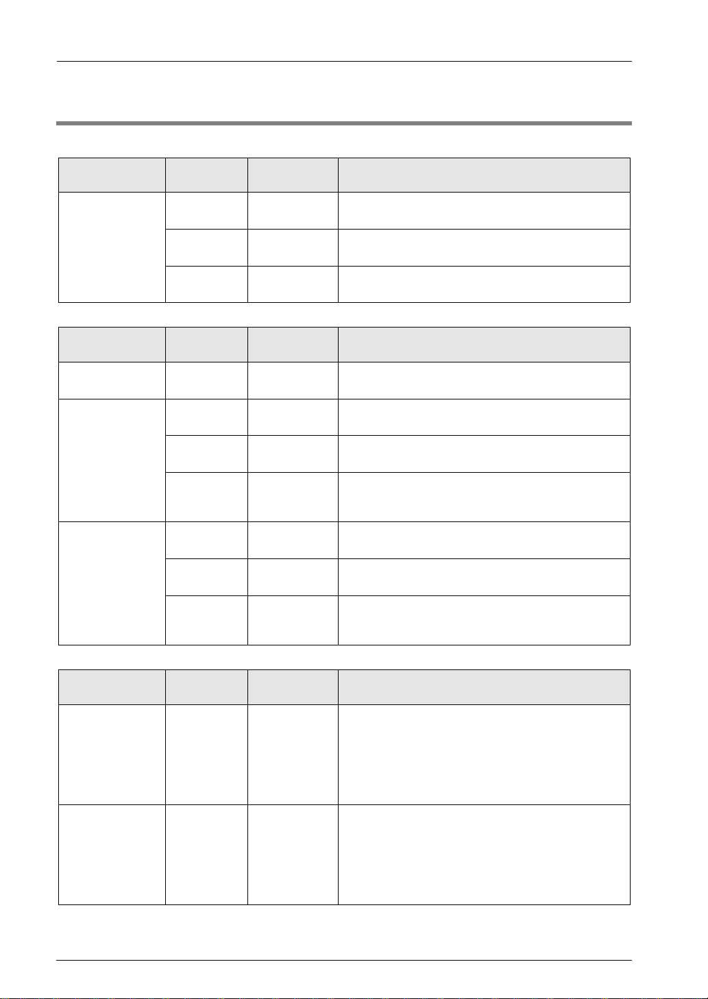
1.2 Unit Type
Input unit
Type
Points
Connection
method
Description
DC input
16 points
Terminal block
12 to 24 V DC (Common polarities + & - common)
Response time switchable
32 points
Connector
24 V DC (Common polarities + & - common)
Response time switchable
64 points
Connector
24 V DC (Common polarities + & - common)
Response time switchable
Output unit
Type
Points
Connection
method
Description
Relay output
16 points
Terminal block
Load current 2 A/1 point and 5 A/1 common
16 points/1 common (with no relay sockets)
Transistor output
sink type
16 points
Terminal block
Load current 1 A/1 point and 5 A/1 common
16 points/1 common
32 points
Connector
Load current 0.3 A/1 point and 3.2 A/1 common
32 points/1 common
64 points
Connector
Load current 0.3 A (8 points: Y0-Y7) and
0.1 A (56 points: Y8-Y3F)
3.2 A/1 common and 32 points/1 common
Transistor output
source type
16 points
Terminal block
Load current 1 A/1 point and 5 A/1 common
16 points/1 common
32 points
Connector
Load current 0.3 A/1 point and 3.2 A/1 common
32 points/1 common
64 points
Connector
Load current 0.3 A (8 points: Y0-Y7), 0.1 A (56 points:
Y8-Y3F)
3.2 A/1 common, 32 points/1 common
I/O mixed unit
Type
Points
Connection
method
Description
DC input/
Transistor output
sink type
Input:
32 points
output:
32 points
Connector
• Input specifications
24 V DC (Common polarities + & - common)
Response time switchable
• Output specifications
Load current 0.3 A (8 points: Y0-Y7) and 0.1 A (24
points: Y8-Y1F)
3.2 A/1 common and 32 points/1 common
DC input/
Transistor output
source type
Input:
32 points
output:
32 points
Connector
• Input specifications
24 V DC (Common polarities + & - common)
Response time switchable
• Output specifications
Load current 0.3 A (8 points: Y0-Y7) and 0.1 A (24
points: Y8-Y1F)
3.2 A/1 common and 32 points/1 common
Page 12

2
Specifications
Page 13

Specifications
2-2
2.1 General Specifications
2.1.1 Common Specifications
Description
Items
Description
Ambient temperature
0°C to +55°C
Storage temperature
-40°C to +70°C
Ambient humidity
10% to 95% (RH) with no condensation (at +25°C)
Storage humidity
10% to 95% (RH) with no condensation (at +25°C)
Breakdown voltage
<DC input and transistor output>
500 V AC for 1 min. (see note 1)
● Between input terminals and output terminals
● Between output terminals and output terminals (between different common terminals)
● Between input terminals and CPU unit power supply terminals/function earth terminals
●
Between output terminals and CPU unit power supply terminals/function earth terminals
<Relay output>
2300 V AC for 1 min. (see note 1)
● Between output terminals and output terminals (between different common terminals)
● Between output terminals and CPU unit power supply terminals/function earth
terminals
Insulation resistance
(Test voltage:
500 V DC)
<DC input and transistor output>
100MΩ or more
● Between input terminals and output terminals
● Between output terminals and output terminals (between different common terminals)
● Between input terminals and CPU unit power supply terminals/function earth terminals
●
Between output terminals and CPU unit power supply terminals/function earth terminals
<Relay output>
100MΩ or more
● Between output terminals and output terminals (between different common terminals)
● Between output terminals and CPU unit power supply terminals/function earth
terminals
Vibration resistance
Conforming to JIS B 3502 and IEC 61131-2
5 to 8.4 Hz, 3.5-mm-wide single amplitude
8.4 to 150 Hz, acceleration 9.8 m/s2
10-minute sweeping in X, Y, and Z directions (1 octave/min.)
Shock resistance
Conforming to JIS B 3502 and IEC 61131-2
147 m/s2 or more, 3 times each in X, Y, and Z directions
Noise resistance
<DC input and transistor output> 1,000 V p-p, pulse widths: 50 ns and 1 μs
<Relay output> 1,500 V p-p, pulse width: 50 ns and 1 μs
Environment
Free from corrosive gases and excessive dust.
EU Directive
applicable standard
EMC Directive: EN 61131-2; Low-voltage Directive: EN 61131-2
Overvoltage category
Category II
Pollution level
Pollution level 2
Note 1) Cutoff current: 5 mA (Factory default setting)
Page 14

2.1 General Specifications
2-3
2.1.2 Current Consumption
Product name
Model number
Internal current
consumption (24 V DC)
DC input unit
16 points
AFP7X16DW
25 mA or less
32 points
AFP7X32D2
30 mA or less
64 points
AFP7X64D2
35 mA or less
16-point-type relay output unit
AFP7Y16R
180 mA or less
Transistor output unit (sink type)
16 points
AFP7Y16T
35 mA or less
32 points
AFP7Y32T
50 mA or less
64 points
AFP7Y64T
75 mA or less
Transistor output unit (source type)
16 points
AFP7Y16P
35 mA or less
32 points
AFP7Y32P
50 mA or less
64 points
AFP7Y64P
75 mA or less
I/O Mixed Unit
32-point DC input
32-point transistor output (sink type)
AFP7XY64D2T
55 mA or less
I/O Mixed Unit
32-point DC input
32-point transistor output (source type)
AFP7XY64D2P
55 mA or less
Page 15

Specifications
2-4
2.2 Input Unit Specifications
2.2.1 16-point-type DC Input Unit
Description
Items
AFP7X16DW
Insulation system
Optical coupler
Rated input voltage
12 to 24 V DC
Rated input current
Approx. 6 mA (at 24 V DC)
Input impedance
Approx. 3.6kΩ
Operating voltage range
10.2 to 26.4 V DC
Minimum ON voltage/Minimum ON
current
9.6 V/2 mA
Maximum OFF voltage/Maximum
OFF current
2.5 V/1 mA
Response time
OFF→ON
0.1 ms or less (changeable with time constant switching function at time
of input)
ON→OFF
0.2 ms or less (changeable with time constant switching function at time
of input)
Input points per common
8 points/1 common
Operating mode indicator
16-point LED indicator (lit in ON state)
External connection method
Terminal block connections (M3 terminal screws)
Weight (unit)
Approx. 125 g
Internal circuit diagram
Terminal layout
Page 16

2.2 Input Unit Specifications
2-5
2.2.2 32-point-type DC Input Unit
Description
Items
AFP7X32D2
Insulation system
Optical coupler
Rated input voltage
24 V DC
Rated input current
Approx. 2.7 mA (at 24 V DC)
Input impedance
Approx. 8.2kΩ
Operating voltage range
20.4 to 26.4 V DC
Min. ON voltage/Min. ON current
19.2 V/2.5 mA
Max. OFF voltage/Max. OFF
current
5 V/1.5 mA
Response time
OFF→ON
0.2 ms max. (changeable with constant switching function at time of input)
ON→OFF
0.2 ms max. (changeable with constant switching function at time of input)
Input points per common
32 points/1 common
Operating mode indicator
32-point LED indicator (lit in ON state)
External connection method
Connector connections (40P conforming to MIL standards)
Weight (unit)
Approx. 95 g
Internal circuit diagram
Terminal layout
The COM terminals are connected internally.
Page 17

Specifications
2-6
2.2.3 64-point-type DC Input Unit
Description
Items
AFP7X64D2
Insulation system
Optical coupler
Rated input voltage
24 V DC
Rated input current
Approx. 2.7 mA (at 24 V DC)
Input impedance
Approx. 8.2kΩ
Operating voltage range
20.4 to 26.4 V DC
Min. ON voltage/Min. ON current
19.2 V/2.5 mA
Max. OFF voltage/Max. OFF current
5 V/1.5 mA
Response time
OFF→ON
0.2 ms max. (changeable with constant switching function at time of
input)
ON→OFF
0.2 ms max. (changeable with constant switching function at time of
input)
Input points per common
32 points/1 common
Operating mode indicator
32-point LED indicator (lit in ON state)
External connection method
Connector connections (40P conforming to MIL standards)
Weight (unit)
Approx. 110 g
Internal circuit diagram
Terminal layout
Limits on number of
simultaneously ON points
Refer to the following figure and reduce the
number of input points that are simultaneously
turned ON.
The COM terminals in the same connector are connected
internally.
Page 18

2.3 Output Unit Specifications
2-7
2.3 Output Unit Specifications
2.3.1 16-point-type Relay Output Unit
Description
Items
AFP7Y16R
Insulation system
Relay insulation
Rated control capacity
2 A 250 V AC (5 A/common) and 2 A 30 V DC (5 A/common)
Minimum load
1 mA 100 mV (resistive load)
Response
time
OFF→ON
Approx. 10 ms
ON→OFF
Approx. 8 ms
Life
Mechanical lifetime
20 million times or more (Frequency of switching: 180 times/min.)
Electrical lifetime
100,000 times or more (Frequency of switching: 20 times/min.)
Surge absorber
Snubber circuit (Leakage current: 0.2 mA or less)
Relay sockets
None
Input points per common
16 points/common
Operating mode indicator
16-point LED indicator (lit in ON state)
External connection method
Terminal block connections (M3 terminal screws)
Weight (unit)
Approx. 180 g
Internal circuit Diagram
Terminal layout
In order to avoid the effects of noise, be sure to ground the function earth
terminal.
Restriction on power supply voltage
Refer to the following figure and reduce the supply voltage according to
the ambient temperature.
Page 19

Specifications
2-8
2.3.2 16-point Sink-type Transistor Output Unit
Description
Items
AFP7Y16T
Insulation system
Optical coupler
Output type
Open collector
Rated load voltage
5 to 24 V DC
Allowable load voltage range
4.75 to 26.4 V DC
Max. load current
1 A
Common limits
5 A/common
Max. inrush current
3 A
OFF state leakage current
1 μA max.
ON state max. voltage drop
0.5 V or less
Response time
OFF→ON
0.05 ms or less (Load current: 0.5 mA or more)
ON→OFF
0.3 ms or less (Load current: 0.5 mA or more)
External power
supply
Voltage
4.75 to 26.4 V DC
Current
70 mA (at 24 V)
Surge absorber
Zener diode
Short-circuit protection
None
Input points per common
16 points/common
Operating mode indicator
16-point LED indicator (lit in ON state)
External connection method
Terminal block connections (M3 terminal screws)
Weight (unit)
Approx. 125 g
Internal circuit diagram
Terminal layout
+
Y0
YF
-
Internal circuit
Load
Load
5 to 24V DC
5 to 24V DC
Page 20

2.3 Output Unit Specifications
2-9
2.3.3 16-point Source-type Transistor Output Unit
Description
Items
AFP7Y16P
Insulation system
Optical coupler
Output type
Open collector
Rated load voltage
5 to 24 V DC
Allowable load voltage range
4.75 to 26.4 V DC
Max. load current
1 A
Common limits
5 A/common
Max. inrush current
3 A
OFF state leakage current
1 μA or less
ON state max. voltage drop
0.5 V or less
Response time
OFF→ON
0.05 ms or less (Load current: 0.5 mA or more)
ON→OFF
0.3 ms or less (Load current: 0.5 mA or more)
External power
supply
Voltage
4.75 to 26.4 V DC
Current
70 mA (at 24 V)
Surge absorber
Zener diode
Short-circuit protection
None
Input points per common
16 points/common
Operating mode indicator
16-point LED indicator (lit in ON state)
External connection method
Terminal block connections (M3 terminal screws)
Weight (unit)
Approx. 125 g
Internal circuit diagram
Terminal layout
+
Y0
Y0
-
Internal circuit
Load
Load
5 to 24V DC
5 to 24V DC
Page 21

Specifications
2-10
2.3.4 32-point Sink-type Transistor Output Unit
Description
Items
AFP7Y32T
Insulation system
Optical coupler
Output type
Open collector
Rated load voltage
5 to 24 V DC
Allowable load voltage range
4.75 to 26.4 V DC
Max. load current
0.3 A (20.4 to 26.4 V DC) and 30 mA (4.75 V DC)
Common limits
3.2 A/common
Max. inrush current
0.6 A
OFF state leakage current
1 μA or less
ON state max. voltage drop
0.5 V or less
Response time
OFF→ON
0.1 ms or less (Load current: 1 mA or more)
ON→OFF
0.3 ms or less (Load current: 1 mA or more)
External power
supply
Voltage
4.75 to 26.4 V DC
Current
110 mA (at 24 V)
Surge absorber
Zener diode
Short-circuit protection
None
Input points per common
32 points/1 common
Operating mode indicator
32-point LED indicator (lit in ON state)
External connection method
Connector connections (40P conforming to MIL standards)
Weight (unit)
Approx. 95 g
Restriction on load current
Refer to the following figure and reduce the load current according to the external power supply voltage.
Page 22

2.3 Output Unit Specifications
2-11
Internal circuit diagram
+
Y0
Y1F
-
Internal circuit
Load
Load
5 to 24V DC
Terminal layout
5 to 24V DC
Although the positive and negative terminals are connected internally, connect these terminals externally as well.
Page 23

Specifications
2-12
2.3.5 32-point Source-type Transistor Output Unit
Description
Items
AFP7Y32P
Insulation system
Optical coupler
Output type
Open collector
Rated load voltage
5 to 24 V DC
Allowable load voltage range
4.75 to 26.4 V DC
Max. load current
0.3 A (26.4 to 20.4 V DC) and 30 mA (4.75 V DC)
Common limits
3.2 A/common
Max. inrush current
0.6 A
OFF state leakage current
1 μA or less
ON state max. voltage drop
0.5 V or less
Response time
OFF→ON
0.1 ms or less (Load current: 2 mA or more)
ON→OFF
0.5 ms or less (Load current: 2 mA or more)
External power
supply
Voltage
4.75 to 26.4 V DC
Current
130 mA (at 24 V)
Surge absorber
Zener diode
Short-circuit protection
None
Input points per common
32 points/1 common
Operating mode indicator
32-point LED indicator (Lit in ON state)
External connection method
Connector connections (40P, conforming to MIL standards)
Weight (unit)
Approx. 95 g
Restriction on load current
Refer to the following figure and reduce the load current according to the external power supply voltage.
Page 24

2.3 Output Unit Specifications
2-13
Internal circuit diagram
+
Y0
Y1F
-
Internal circuit
Load
Load
5 to 24V DC
Terminal layout
5 to 24V DC
Although the positive and negative terminals are connected internally, connect these terminals externally as well.
Page 25

Specifications
2-14
2.3.6 64-point Sink-type Transistor Output Unit
Description
Items
AFP7Y64T
Insulation system
Optical coupler
Output type
Open collector
Rated load voltage
5 to 24 V DC
Allowable load voltage range
4.75 to 26.4 V DC
Max. load
current
0.3 A specifications
(Y0 to 7)
0.3 A (20.4 to 26.4 V DC) and 30 mA (4.75 V DC)
0.1 A specifications
(other than the above)
0.1 A (20.4 to 26.4 V DC) and 15 mA (4.75 V DC)
Common limits
3.2 A/common
Max. inrush current
0.6 A
OFF state leakage current
1 μA or less
ON state max. voltage drop
0.5 V or less
Response time
OFF→ON
0.1 ms or less (Load current: 2 mA or more)
ON→OFF
0.3 ms or less (Load current: 2 mA or more)
External power
supply
Voltage
4.75 to 26.4 V DC
Current
70 mA/common (at 24 V)
Surge absorber
Zener diode
Short-circuit protection
None
Input points per common
32 points/1 common
Operating mode indicator
32-point LED indicator (Lit in ON state, switchable)
External connection method
Connector connections (40P x 2, conforming to MIL standards)
Weight (unit)
Approx. 115 g
Restriction on load current
Refer to the following figure and reduce the load current according to the external power supply voltage.
0.3 A specifications (Y0 to Y7)
0.1 A specifications (other than Y0 to Y7)
Page 26

2.3 Output Unit Specifications
2-15
Internal circuit diagram
+
Y0/Y20
Y1F/Y3F
-
Internal circuit
Load
Load
5 to 24V DC
Terminal layout
CN1 CN2
5 to 24V DC
5 to 24V DC
Although the positive and negative terminals are connected internally, connect these terminals externally as well.
Page 27

Specifications
2-16
2.3.7 64-point Source-type Transistor Output Unit
Description
Items
AFP7Y64P
Insulation system
Optical coupler
Output type
Open collector
Rated load voltage
5 to 24 V DC
Allowable load voltage range
4.75 to 26.4 V DC
Max. load
current
0.3 A specifications
(Y0 to 7)
0.3 A (20.4 to 26.4 V DC) and 30 mA (4.75 V DC)
0.1 A specifications
(other than the above)
0.1 A (20.4 to 26.4 V DC) and 15 mA (4.75 V DC)
Common limits
3.2 A/common
Max. inrush current
0.6 A
OFF state leakage current
1 μA or less
ON state max. voltage drop
0.5 V or less
Response time
OFF→ON
0.1 ms or less (Load current: 2 mA or more)
ON→OFF
0.5 ms or less (Load current: 2 mA or more)
External power
supply
Voltage
4.75 to 26.4 V DC
Current
90 mA/common (at 24 V)
Surge absorber
Zener diode
Short-circuit protection
None
Input points per common
32 points/1 common
Operating mode indicator
32-point LED indicator (Lit in ON state, switchable)
External connection method
Connector connections (40P x 2, conforming to MIL standards)
Weight (unit)
Approx. 115 g
Restriction on load current
Refer to the following figure and reduce the load current according to the external power supply voltage.
0.3 A specifications (Y0 to Y7)
0.1 A specifications (other than Y0 to Y7)
Page 28

2.3 Output Unit Specifications
2-17
Limits on number of simultaneously ON points
53475555
64
53
32
Ambient
Temperature(℃)
at 24V DC
at 26.4V DC
Number of
points per
common
which are
simultaneous on
Internal circuit diagram
+
Y0/Y20
Y1F/Y3F
-
Internal circuit
Load
Load
5 to 24V DC
Terminal layout
5 to 24V DC 5 to 24V DC
CN1 CN2
Although the positive and negative terminals are connected internally, connect these terminals externally as well.
Page 29

Specifications
2-18
2.4 I/O Mixed Unit Specifications
2.4.1 32-point DC Input/32-point Sink Type Transistor Output
Description
Items
AFP7XY64D2T
Input specifications
Insulation system
Optical coupler
Rated input voltage
24 V DC
Rated input current
Approx. 2.7 mA (at 24 V DC)
Input impedance
Approx. 8.2kΩ
Operating voltage range
20.4 to 26.4 V DC
Min. ON voltage/Min. ON current
19.2 V/2.5 mA
Max. OFF voltage/Max. OFF current
5 V/1.5 mA
Response time
OFF→ON
0.2 ms or less (changeable with time constant switching
function at time of input)
ON→OFF
0.2 ms or less (changeable with time constant switching
function at time of input)
Input points per common
32 points/1 common
Output specifications
Insulation system
Optical coupler
Output type
Open collector
Rated load voltage
5 to 24 V DC
Allowable load voltage range
4.75 to 26.4 V DC
Max. load current
0.3 A specifications
(Y0 to 7)
0.3 A (20.4 to 26.4 V DC) and 30 mA (4.75 V DC)
0.1 A specifications
(other than the above)
0.1 A (20.4 to 26.4 V DC) and 15 mA (4.75 V DC)
Common limits
3.2 A/common
Max. inrush current
0.6 A
OFF state leakage current
1 μA or less
ON state max. voltage drop
0.5 V or less
Response time
OFF→ON
0.1 ms or less (Load current: 2 mA or more)
ON→OFF
0.3 ms or less (Load current: 2 mA or more)
External power
supply
Voltage
4.75 to 26.4 V DC
Current
70 mA (at 24 V)
Surge absorber
Zener diode
Short-circuit protection
None
Input points per common
32 points/1 common
Operating mode indicator
32-point LED indicator (lit in ON state)
External connection method
Connector connections (40P conforming to MIL standards)
Weight (unit)
Approx. 115 g
Page 30

2.4 I/O Mixed Unit Specifications
2-19
Internal circuit diagram
Limits on number of simultaneously ON points (common to input/output)
Restriction on load current
Refer to the following figure and reduce the load current according to the external power supply voltage.
0.3 A specifications (Y0 to Y7)
0.1 A specifications (other than Y0 to Y7)
Page 31

Specifications
2-20
Terminal layout
The COM terminals are connected internally.
CN2
5 to 24V DC
Although the positive and negative terminals are
connected internally, connect these terminals externally
as well.
Page 32

2.4 I/O Mixed Unit Specifications
2-21
2.4.2 32-point DC Input/32-point Source Type Transistor Output
Description
Items
AFP7XY64D2P
Input specifications
Insulation system
Optical coupler
Rated input voltage
24 V DC
Rated input current
Approx. 3.4 mA (at 24 V DC)
Input impedance
Approx. 7.5kΩ
Operating voltage range
20.4 to 26.4 V DC
Min. ON voltage/Min. ON current
19.2 V/2.5 mA
Max. OFF voltage/Max. OFF current
5 V/1.5 mA
Response time
OFF→ON
0.2 ms or less (changeable with time constant switching
function at time of input)
ON→OFF
0.2 ms or less (changeable with time constant switching
function at time of input)
Input points per common
32 points/1 common
Output s
pecifications
Insulation system
Optical coupler
Output type
Open collector
Rated load voltage
5 to 24 V DC
Allowable load voltage range
4.75 to 26.4 V DC
Max. load current
0.3 A specifications
(Y0 to 7)
0.3 A (20.4 to 26.4 V DC) and 30 mA (4.75 V DC)
0.1 A specifications
(other than the above)
0.1 A (20.4 to 26.4 V DC) and 15 mA (4.75 V DC)
Common limits
3.2 A/common
Max. inrush current
0.6 A
OFF state leakage current
1 μA or less
ON state max. voltage drop
0.5 V or less
Response time
OFF→ON
0.1 ms or less (Load current: 2 mA or more)
ON→OFF
0.5 ms or less (Load current: 2 mA or more)
External power
supply
Voltage
4.75 to 26.4 V DC
Current
90 mA/common (at 24 V)
Surge absorber
Zener diode
Short-circuit protection
None
Input points per common
32 points/1 common
Operating mode indicator
32-point LED indicator (Lit in ON state, switchable)
External connection method
Connector connections (40P x 2, conforming to MIL
standards)
Weight (unit)
Approx. 115 g
Page 33

Specifications
2-22
Internal circuit diagram
Limits on number of simultaneously ON points (common to input/output)
Restriction on load current
Refer to the following figure and reduce the load current according to the external power supply voltage.
0.3 A specifications (Y0 to Y7)
0.1 A specifications (other than Y0 to Y7)
Page 34

2.4 I/O Mixed Unit Specifications
2-23
Terminal layout
The COM terminals are connected internally.
5 to 24V DC
CN2
Although the positive and negative terminals are
connected internally, connect these terminals externally
as well.
Page 35

Specifications
2-24
2.5 Input Time Constant Switching Function
2.5.1 Overview of Function
Software tools can change the input time constant.
Select the set time from
None/0.1/0.5/1.0/5.0/10.0/20.0/70.0/[ms]
and set the selected set time on a unit-by-unit basis.
The set constant is added to the response time specific to the hardware of each unit.
Example) 16-point Input Unit
Specific response time OFF→ON: 0.1 ms, ON→OFF: 0.2 ms
If “1.0 ms” is set for this unit, the following overall response periods will result.
Response time after setting OFF→ON: 1.1 ms, ON→OFF: 1.2 ms
The time constant to be set has a margin of error, which should be kept in mind when
selecting the set value. The accuracy of each time constant is shown in the table below.
Time
constant
Setting
Min.
Max.
No time constant
settings
-
-
0.1 ms
0.1 ms
0.2 ms
0.5 ms
0.3 ms
0.7 ms
1 ms
0.7 ms
1.3 ms
5 ms
3.0 ms
5.2 ms
10 ms
6.0 ms
10.4 ms
20 ms
12.1 ms
20.7 ms
70 ms
48.6 ms
82.8 ms
2.5.2 Setting by FPWIN7 Software Tool
The input time constant can be set in the I/O map of the FPWIN GR7 configuration menu.
P R OC E DUR E
1. Select “Options" → "FP7 Configuration" from the menu bar.
The FP7 Configuration dialog box is displayed.
2. Select "I/O Map."
3. Double-click the "Operating Unit" in the target slot.
The Select Unit dialog box is displayed.
4. Select the target Digital I/O Unit and input time constant, and press the [OK]
button.
The information set is registered with the I/O map.
Page 36

2.5 Input Time Constant Switching Function
2-25
Page 37

Specifications
2-26
Page 38

3
Wiring
Page 39

Wiring
3-2
3.1 Precautions on Wiring
3.1.1 Before Wiring
Before the wiring, carefully confirm the specifications of the unit to be wired.
Each unit varies in ambient temperature, the number of simultaneously ON points, and
supply voltage limitations.
3.1.2 Precautions on Input Wiring
Connection of photoelectric sensor and proximity sensor
Page 40

3.1 Precautions on Wiring
3-3
Connection of LED-equipped reed switch
With a LED is connected to an input contact such as LED-equipped reed switch, make sure
that the voltage value applied to the input terminal of PLC is greater than on voltage value.
In particular, take care when connecting a number of switches in series.
Connection of two-wire type sensor
If the input of the PLC is not turned off because of leakage current from the two-wire type
sensor, the connection of a bleeder resistor is recommended, as shown below.
Using 16-point type input unit (AFP7X16DW)
(Off voltage: 2.5 V; input impedance: 3.6kΩ)
I: Sensor‘s leakage current (mA)
R: Bleeder resistor (kΩ)
The off voltage of the input is 2.5 V. Therefore, select an R so that the voltage
between the COM terminal and the input terminal will be less than 2.5 V.
The input impedance is 3.6kΩ.
I ×
3.6R
≤2.5. Therefore, R≤
9
(kΩ)
3.6+R
3.6I-2.5
The wattage W of the resistor is:
W=
(Power supply voltage)2
R
In the actual selection, use a value that is 3 to 5 times the value of W.
Page 41

Wiring
3-4
Connection of LED-equipped limit switch
With the LED-equipped limit switch, if the input of the PLC is not turned off or if the LED of the
limit switch is kept on because of the leakage current, the connection of a bleeder resistor is
recommended, as shown below.
Using 16-point type input unit (AFP7X16DW)
(Off voltage: 2.5 V; input impedance: 3.6kΩ)
r: Internal resistor of limit switch (kΩ)
R: Bleeder resistor (kΩ)
The input off voltage is 2.5 V. Therefore, when the power supply voltage is 2.4 V,
the input impedance is 3.6kΩ.
I ×
2.4-2.5
or more
r
Obtain R so that the above current will flow. Obtain I in the same way as when using
the above 2-wire sensor.
R≤ 9 (kΩ) W=
(Power supply voltage)2
×(3 to 5)
3.6I-2.5
R
Page 42

3.1 Precautions on Wiring
3-5
3.1.3 Precautions on Output Wiring
Connection of inductive loads
When connecting an inductive load, a protective circuit should be installed in parallel with the
load.
When connecting the DC type inductive loads and relay type output unit, be sure to connect a
diode for protective circuit across the ends of the load. This will affect the life of the relay.
When using an AC inductive load (Relay output type)
Connection of capacitive loads
When connecting the loads with large in-rush currents, be sure to connect a protection circuit
in series with the load.
Precautions for overload
To protect the units from overloading, it is recommended to attach an external fuse for each
point.
There are times that the elements for the output units cannot be protected even if external
fuses are connected.
Page 43

Wiring
3-6
Earth
In order to avoid the effects of noise, be sure to ground the AFP7Y16R terminal.
The grounding connection should have a resistance not in excess of 100Ω.
The point of grounding should be as close to the PLC as possible. The ground wire should
be as short as possible.
Sharing the ground with another device may have an adverse effect. Therefore, be sure that
grounding is dedicated.
Notes:
Sharing the ground with another device may have an adverse effect. Therefore, be sure that
grounding is dedicated.
Page 44

3.2 Wiring I/O Unit of Terminal Block Type
3-7
3.2 Wiring I/O Unit of Terminal Block Type
3.2.1 Suitable Wires and Solderless Terminals
Suitable wires
Suitable wires
Tightening torque
AWG22 to 14 (0.3 mm2 to 2.0 mm2)
0.5 to 0.6 N・m
Solderless terminal
M3 terminal screws are used for the terminal. The following suitable solderless terminals are
recommended for the wiring to the terminals.
Suitable solderless terminal
Manufacturer
Shape
Part No.
Suitable wires
J.S.T. Mfg Co., Ltd.
Fork type
1.25-B3A
0.25 to 1.65 mm2
Round type
1.25-MS3
Fork type
2-N3A
1.04 to 2.63 mm2
Round type
2-MS3
Page 45

Wiring
3-8
3.2.2 Wiring to Terminal Block
Remove the terminal block before beginning the wiring operations.
To remove the terminal block, push downward the release lever located at the top of the
terminal block.
Release lever
for terminal block
<Bottom of unit>
Lock button
Note:
Install the terminal block by inserting it all the way to its original position and pressing the lock
button on the bottom of the unit. Then confirm that the terminal block is securely attached and
cannot be removed.
Page 46

3.3 Wiring Connector-type I/O Unit
3-9
3.3 Wiring Connector-type I/O Unit
3.3.1 Wiring with Connectors for Wire-pressed Terminal Cable
Specifications of connectors for wire-pressed terminal cable
This is a connector allowing loose wires to be connected without removing the wire’s
insulation. A dedicated pressure connection tool is required to connect the loose wires.
Suitable wires (strand wire)
Size
Nominal crosssectional area
Insulation
thickness
Rated current
AWG22
0.3 mm2
1.5 to 1.1 dia.
3 A
AWG24
0.2 mm2
Wiring with connectors for wire-pressed terminal cable (provided with unit)
Manufacturer
Composition of
components
Unit type and required quantity
32-point-type Input Unit
32-point-type Output Unit
64-point-type Input Unit
64-point-type Output Unit
I/O Mixed Unit
Panasonic-made
Housing
(40P)
1 x 1 set
1 x 2 sets
Semi-cover
(40P)
2 x 1 set
2 x 2 sets
Contact
(for AWG22 or 24)
5 pins
8 x 1 set
8 x 2 sets
(Note) The 32-point-type unit is provided with one set and the 64-point-type and I/O mixed units are provided with two
sets each. If you need more connectors, purchase AFP2801 (2 sets/pack).
Page 47

Wiring
3-10
Pressure connection tool
Manufacturer
Product No.
Panasonic
AXY52000FP
3.3.2 Assembly of Connector for Wire-pressed Terminal Cable
The wire end can be directly crimped without removing the wire’s insulation, saving labor.
(Procedure)
1. Bend the contact back from the carrier, and set it in the pressure connection tool.
2. Insert the wire without removing its insulation until it stops, and lightly grip the tool.
3. After press-fitting the wire, insert it into the housing.
Page 48

3.3 Wiring Connector-type I/O Unit
3-11
4. When all wires have been inserted, fit the semi-cover into place.
K E Y P OINT S
Contact puller pin to redo wiring
If there is a wiring mistake or the wire is incorrectly pressure-connected, the contact puller pin
provided with the fitting can be used to remove the contact.
Page 49

Wiring
3-12
3.3.3 Wiring with Flat Cable Connectors
Wiring with flat cable connectors
When connecting with a flat cable connector, the relationship between the cable number and
I/O number is shown below.
Correspondence table of flat cable No. and I/O No.
CN1 group
Correspondence table of flat cable No. and I/O No.
CN2 group
Cable
No.
Input
No.
Output
No.
Cable
No.
Input
No.
Output
No.
Cable
No.
Input
No.
Output
No.
Cable
No.
Input
No.
Output
No.
1
X0
Y0 21
X10
Y10 1
X20
Y20 21
X30
Y30
2
X8
Y8 22
X18
Y18 2
X28
Y28 22
X38
Y38 3 X1
Y1 23
X11
Y11 3
X21
Y21 23
X31
Y31 4 X9
Y9 24
X19
Y19 4
X29
Y29 24
X39
Y39
5
X2
Y2 25
X12
Y12 5
X22
Y22 25
X32
Y32
6
XA
YA 26
X1A
Y1A 6
X2A
Y2A 26
X3A
Y3A 7 X3
Y3 27
X13
Y13 7
X23
Y23 27
X33
Y33 8 XB
YB 28
X1B
Y1B 8
X2B
Y2B 28
X3B
Y3B 9 X4
Y4 29
X14
Y14 9
X24
Y24 29
X34
Y34
10
XC
YC 30
X1C
Y1C 10
X2C
Y2C 30
X3C
Y3C
11
X5
Y5 31
X15
Y15 11
X25
Y25 31
X35
Y35
12
XD
YD 32
X1D
Y1D 12
X2D
Y2D 32
X3D
Y3D
13
X6
Y6 33
X16
Y16 13
X26
Y26 33
X36
Y36
14
XE
YE 34
X1E
Y1E 14
X2E
Y2E 34
X3E
Y3E
15
X7
Y7 35
X17
Y17 15
X27
Y27 35
X37
Y37
16
XF
YF 36
X1F
Y1F 16
X2F
Y2F 36
X3F
Y3F
17
COM
- 37
COM
- 17
COM
- 37
COM
-
18
COM
- 38
COM
- 18
COM
- 38
COM
-
19
NC +
39
NC +
19
NC +
39
NC + 20
NC +
40
NC +
20
NC +
40
NC
+
Flat-cable connection diagram for 64-point-type input unit, 64-point-type output unit, I/O
mixed unit
Page 50

3.3 Wiring Connector-type I/O Unit
3-13
Suitable wires (strand wire)
Size
Pitch
Rated current
AWG28
(7 wires/0.127 dia.)
1.27 mm
1 A
Page 51

Record of changes
Manual No.
Date
Record of Changes
WUME-FP7DIO-01
Mar.2013
First Edition
WUME-FP7DIO-02
Oct.2013
Second Edition
WUME-FP7DIO-03
Oct.2020
Third Edition
- Error correction
Page 52

Order Placement R eco mm en dat io ns a n d C on si der at io ns
The Products and Speci fica tion s liste d in this do cumen t are sub ject to change (i nclu ding
specifications, manufa cturin g facil ity an d discon tinui ng the Pr oduc ts) as o ccasion ed by the
improvements of P ro duct s. Co ns eq uen tl y, w he n y ou pla ce o rd ers f or t hese Pr o duc ts , Pa nason ic
Industrial Devi ce s SUNX as ks y ou to c on ta ct one o f o ur c ustom er s er vi ce re p res en ta tives a nd
check that the details liste d in the do cument ar e comm ensu rate wi th the mos t up-to-d ate
information.
[Safety precautio ns]
Panasonic Indus trial De vices SUN X is consis tently st riving t o improve q uality an d reliabi lity.
However, the fa ct r emai ns th at elec tr ic al c ompon e nts a nd devi ce s ge ne rally cau se f ailur es
at a given stat is ti cal pro ba bi lity. F ur th er more, the ir d urabi li ty v ar ies w i th us e envir on me nt s
or use conditio ns . In t his r es pect, c he ck f or ac t ual ele ct ric al com po nen ts and d ev ic es un de r
actual conditio ns b efor e u se . Conti nu ed u sa ge in a s ta te of d eg ra de d condi t ion m ay caus e th e
deteriorated in su latio n . T hu s, it m ay r es ul t in a bno rmal h eat , sm ok e or fi re. Ca rr y out s af et y
design and perio dic m ainte nance i nclu ding redun dancy de sign , des ign f or fi re spre ad pr even tion ,
and design for malfunc tion preve ntion so th at no acc iden ts resu lting in in jury or death , fire
accidents, or socia l damag e will be cause d as a result of failure of the Pr oduct s or endi ng
life of the Products.
The Products ar e des igne d a nd m an ufact ur ed f or the in du st ri al indo or e nvi ro nmen t us e. Ma ke
sure standards, l aws a nd re gu la tions i n ca se the P roduc ts a re in corp or ate d t o mac hi ne ry, s yste m,
apparatus, and so fo rth. Wi th reg ard t o th e men ti o ned a bove , c on fi rm the co n for mi ty o f t he
Products by yourself .
Do not use th e P ro du cts f or t he ap plic at io n w hi ch b re ak do wn or m al fu nct io n of Pro du cts m ay
cause damage to the body or property .
i) usage intended t o p rote ct t he bo dy a nd e nsu re secur it y of li fe
ii)application wh ich th e perfo rmance de grad ation or qual ity pro blems, such as br eakd own,
of the Products may directly result in da mag e t o t he b od y or pr op er ty
It is not allow ed th e us e of Pr od uct s by i ncorp or a tin g in to ma ch in er y and sy ste ms ind ica te d
below because the conformit y, p er forma nc e, a nd qua lit y of Prod uc ts a re no t guar an te ed un der
such usage.
i) transport machinery (cars , trains, boats and ship s, etc .)
ii) control equipment f or tran sportat ion
iii) disaster-preve ntion equ ipme nt / secu rity eq uipm ent
iv) control equipment for electric power generation
v) nuclear control syste m
vi) aircraft equipment , aeros pace equi pmen t, and s ubmar ine rep eater
vii) burning appliance s
viii) military devices
ix) medical devicesقexcept for general controls ك
x) machinery and sy ste ms w hi ch espe ci al ly requ ir e th e high le ve l of reli ab i lit y and saf et y
[Acceptance ins pec ti on]
In connection with t he Prod ucts y ou have p urcha se d fr om us or with t he Prod u cts d elivere d
to your premises, pleas e p erf orm an ac cept an ce in specti on w ith a ll d ue speed a nd, i n conne ct ion
with the handling of our P roduc ts both bef ore and d urin g the acc epta nce inspe ctio n, ple ase
give full considerat ion t o the cont rol a nd pre ser va tion o f our P ro du cts.
[Warranty period]
Unless otherwise stipulated by both parties, the warranty period of our Products is 3 years
after the purchase by you or after their delivery to the location specified by you.
The consumable it ems suc h as battery , relay, f ilter and othe r suppl emental mater ials are exc luded
from the warranty.
[Scope of warranty]
In the event that Pana so nic Ind us tri al D evic es SUN X confirms any failures o r defe ct s of
the Products by reasons s olel y attr ibutabl e to Pana soni c Indu strial De vices S UNX du ring th e
warranty period, Pan asonic Indu strial Devi ces SUNX shall su pply the repl acements of t he Products,
parts or replace and/or r epai r the def ec ti ve p ort ion by f ree of ch ar ge a t the locat io n whe re
the Products were purch ase d or de livered t o your pr emis es as soo n as possib le.
However, the following failures and defects are not covered by warranty and we are not responsible
for such failures and d efe cts.
(1) When the failure or defect was caused by a specif ica tion, standa rd, hand ling m ethod ,
etc. which was s pe ci fied b y y ou.
(2) When the failure or defect was caused af ter pu rchas e or del ivery to your prem ises by
an alteration in constr uct ion, pe rforman ce, sp ecifi cati on, etc. wh ich di d not invol ve
us.
(3) When the failure o r def ec t wa s caus ed by a p henom en o n t ha t co uld n ot be pre di c ted by
the technology a t pu rchas i ng or c ontra ct ed t im e.
(4) When the use of ou r Pro du c ts de vi at ed fr om t he sc op e of t he c ond it ions a nd en viro nm en t
set forth in the i ns tru ct ion ma nu al and sp ec if ica ti ons.
(5) When, after our Pr oduct s w ere inc or por at ed int o y ou r prod uc ts or e qu ip me nt fo r us e, d amage
resulted which c ou ld have bee n av oided i f yo ur prod ucts o r eq uip ment h ad be en equ ip pe d
with the functio ns , const r uct io n, etc. t he p ro visio n of w hich is a cc ep ted p ra ctic e in
the industry.
(6) When the failure or de fec t wa s cause d by a natu r al di sa ster or o th er forc e ma je ur e.
(7) When the equipment is dam aged due to corro sion c aused by corro sive gases etc. in the
surroundings.
The above terms and cond itio ns sha ll not cove r any ind uced damage s by the fa ilure or defect s
of the Products, and not cover your production items whic h are pro duced or f abricat ed by usi ng
the Products. In a ny ca se, ou r re sp onsib il it y for co mpe ns at io n is li mi te d t o t he am ou nt paid
for the Products .
[Scope of service]
The cost of del iv er ed P rod uc ts
In case any such servic e is need ed, con tact our s ales re prese ntat ive.
does not includ e t he co st o f d is patc hi ng an engin ee r, et c.
3DQDVRQLF,QGXVWULDO'HYLFHV ㄟㄡㄚㄤ &R/WG
6;6<
Page 53

Page 54

Please contact ..........
Panasonic Industrial Devices SUNX Co., Ltd.
https://panasonic.net/id/pidsx/global
Please visit our website for inquiries and about our sales network.
October, 2020 PRINTED IN JAPAN
© Panasonic Industrial Devices SUNX Co., Ltd. 2020
WUME-FP7DIO-03
 Loading...