

Panasonic FP2, FP2-MW Technical Manual

PROGRAMMABLE CONTROLLER
FP2 Multi-wire Link Unit
Technical Manual
ARCT1F302E-2
2008.11

Safety Precautions
Observe the following notices to ensure personal safety or to prevent accidents.
To ensure that you use this product correctly, rea
Make sure that you fully understand the product and information on safety.
This manual uses two safety flags to indicate different levels of danger.
WARNING
If critical situations that could lead to user’s death or serious injury is assumed by
mishandling of the product.
-Always take precautions to ensure the overall safety of your system, so that the whole system
remains safe in the event of failure of this produ
-Do not use this product in areas with inflammable gas. It could lead to an explosion.
-Exposing this product to excessive heat or open flames could ca
or other electronic parts.
CAUTION
If critical situations that could lead to user’s injury or only property damage is assumed
by mishandling of the product.
-To prevent excessive exothermic heat or smoke generation, use this pro
the maximum of the characteristics and performance that are assured in these specifications.
-Do not dismantle or remodel the product. It could ca
generation.
-Do not touch the terminal while turning on electri
-Use the external devices to function the
-Connect the wires or connectors securely.
The loose connection could cause excessive exoth
-Do not allow foreign matters such as liquid, flammable materials, metals to go into the inside of the
duct. It could cause excessive exothermic heat or smoke generation.
pro
-Do not undertake construction (such as connection and di
It could lead to an electric shock.
emergency stop and interlock circuit.
d this User’s Manual thoroughly before use.
ct or other external factor .
use damage to the lithium battery
duct at the values less than
use excessive exothermic heat or smoke
city. It could lead to an electric shock.
ermic heat or smoke generation.
sconnection) while the power supply is on.
Copyright / Trademarks
-This manual and its contents are copyrighted.
-You may not copy this manual,in whole or part,without written consent of Pa
Works.,Ltd.
-Windows and Windows NT are registered tradema
United States and/or other countries.
-All other company names and product name
trademarks of their respective owners.
-Matsushita Electric Works,Ltd. pursues a policy of co
Design and performance of its products, therefo
product without notice.
rks of Microsoft Corporation in the
s are trademarks or registered
ntinuous improvement of the
re,we reserve the right to change the manual/
nasonicElectric
BNTN


Table of Contents FP2 Multi-wire Link Unit
Table of Contents
Before You Start
Chapter 1 General Specifications
1.1 How the Multi-wire Link Unit Works 1 - 3.................................
1.1.1 MEWNET-W Mode 1 - 4.........................................
1.1.2 MEWNET-W2 Mode 1 - 5........................................
1.1.3 MEWNET-F Mode 1 - 6.........................................
1.2 Specifications 1 - 8....................................................
1.2.1 General Specifications 1 - 8......................................
1.2.2 Transmission Specifications 1 - 9.................................
1.2.3 Performance Specifications 1 - 10.................................
1.2.3.1 W and W2 Modes 1 - 10................................
1.2.3.2 F Mode 1 - 11.........................................
1.2.4 Transmission Cable Specifications 1 - 12...........................
1.3 Restrictions When Combinations Are Used 1 - 14..........................
1.3.1 Restrictions on the CPU 1 - 14....................................
1.3.2 Restrictions on the Installation Position 1 - 14.......................
1.3.3 Restrictions on the Number of Units that can be Installed 1 - 15.......
1.4 Confirming the Design Contents 1 - 16...................................
1.4.1 Confirming the Current Consumption 1 - 16.........................
1.4.2 Confirming I/O Allocations 1 - 16..................................
1.4.3 Confirmation When Multiple Units are Installed 1 - 17................
v......................................................
Chapter 2 Parts and Its Functions
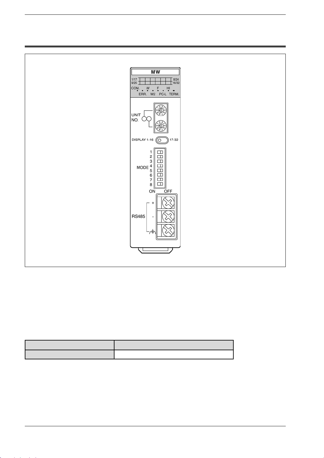
2.1 Parts Terminology 2 - 3................................................
2.1.1 Status Indicator LEDs 2 - 5.......................................
2.1.2 Slave Station Number Display Selector Switch 2 - 6.................
2.2 Switch Settings 2 - 7...................................................
2.2.1 Station Number Selector 2 - 7....................................
2.2.2 Mode Selector Switches (1) 2 - 8..................................
2.2.3 Mode Selector Switches (2) 2 - 9..................................
Chapter 3 Wiring
3.1 Wiring 3 - 3..........................................................
3.1.1 Transmission Cable Wiring 3 - 3..................................
3.1.2 Crimp Terminal Specifications 3 - 4................................
ii

FP2 Multi-wire Link Unit
Chapter 4 MEWNET-W Mode
4.1 W Mode Functions 4 - 3................................................
4.1.1 PC Link Function 4 - 3...........................................
4.1.2 Data Transfer Function 4 - 3......................................
4.1.3 Remote Programming Function 4 - 3...............................
4.2 PC Link 4 - 4.........................................................
4.2.1 Preparing to Use PC Link 4 - 4....................................
4.2.2 Link Area Allocations 4 - 4.......................................
4.2.3 Link Area Allocation Example 4 - 5................................
4.2.4 Sample PC Link Program 4 - 8....................................
4.2.5 Precautions When Allocating Link Areas 4 - 10......................
Appendix A What to Check If a Problem Occurs
A.1 If the CPU ERROR LED Lights 5 - 3.....................................
A.2 Confirming the Mode Being Used 5 - 4...................................
A.3 What to Check When the ERR LED Is Lighted or Blinking 5 - 5..............
A.4 What to Do If a Transmission Error Occurs 5 - 6...........................
Table of Contents
Appendix B Dimensions
Index
Record of changes
i-1................................................................
R-1...............................................
iii

Before You Start
FP2 Multi-wire Link Unit
Before You Start
CPU Versions Supported
This unit supports CPU Ver. 1.05 and subsequent versions. Confirm the version on the
side panel seal on the CPU, or on the [STATUS DISPLAY] in the [MONITOR] menu of
the NPST-GR.
Selecting Cables
Cables which can be used with this unit vary depending on the mode being used. For
information on cable connections, refer to section 3.1.
Mode Cables used
MEWNET-W
MEWNET-W2
MEWNET-F
Twistedpair cable
Twistedpair cable, VCTF cable
About Selecting MEWNET-W2
In order to use the FP2 Multi-wire link unit in MEWNET-2 mode, the user must write
a program on a level of about 300 steps. Proceed only after carefully going over the
specifications.
Please inquire about more detailed materials regarding MEWNET-W2.
iv

FP2 Multi-wire Link Unit
Before You Start
Reference Manuals
The following reference manuals are available for use with this unit, and should be
used in conjunction with this manual.
Manual name Manual number Description
FP2 Hardware
manual
FP3/FP5 W TYPE
(WIRE) LINK
SYSTEM Manual
FP3/FP5
REMOTE I/O
SYSTEM Manual
ARCT1F298E
ACG-M0032
ACG-M0028
This introduces the hardware configuration, wiring
methods, I/O allocation, maintenance methods, and
other information pertaining to the FP2 series.
This introduces the hardware configuration, wiring
methods, I/O allocation, maintenance methods, and
other information pertaining to the MEWNET-W.
Refer to this manual when using the MEWNET-W
mode.
This introduces the hardware configuration, wiring
methods, I/O allocation, maintenance methods, and
other information pertaining to the MEWNET-F.
Refer to this manual when using the MEWNET-F
mode.
v


Chapter 1
General Specifications
1.1 How the Multi-wire Link Unit Works 1 - 3........
1.1.1 MEWNET-W Mode 1 - 4...............
1.1.2 MEWNET-W2 Mode 1 - 5..............
1.1.3 MEWNET-F Mode 1 - 6................
1.2 Specifications 1 - 8............................
1.2.1 General Specifications 1 - 8............
1.2.2 TransmissionSpecifications 1 - 9........
1.2.3 Performance Specifications 1 - 10.......
1.2.3.1 W and W2 Modes 1 - 10........
1.2.3.2 F Mode 1 - 11.................
1.2.4 Transmission Cable Specifications 1 - 12.
1.3 Restrictions When Combinations Are Used 1 - 14.
1.3.1 Restrictions on the CPU 1 - 14..........
1.3.2 Restrictions on the Installation
Position 1 - 14........................
1.3.3 Restrictions on the Number of Units
that can be Installed 1 - 15.............
1.4 Confirming the Design Contents 1 - 16...........
1.4.1 Confirming the Current
Consumption 1 - 16...................
1.4.2 Confirming I/O Allocations 1 - 16........
1.4.3 Confirmation When Multiple Units are
Installed 1 - 17........................

General Specifications FP2 Multi-wire Link Unit
1-2
1.1 How the Multi-wire Link Unit Works
1.1 How the Multi-wire Link Unit Works
General SpecificationsFP2 Multi-wire Link Unit
An overview of the multi-wire link unit
The following functions can be accessed with a single FP2 Multi-wire link unit
(FP2-MW), by changing the positions of the mode selector switches (2).
D MEWNET-W network: Hereafter referred to as the W mode.
D MEWNET-W2 network: Hereafter referred to as the W2 mode.
D MEWNET-F network: Hereafter referred to as the F mode.
Name Order number
FP2 Multi-wire link unit
FP2-MW
1-3
General Specifications FP2 Multi-wire Link Unit
/
py
p
1.1 How the Multi-wire Link Unit Works
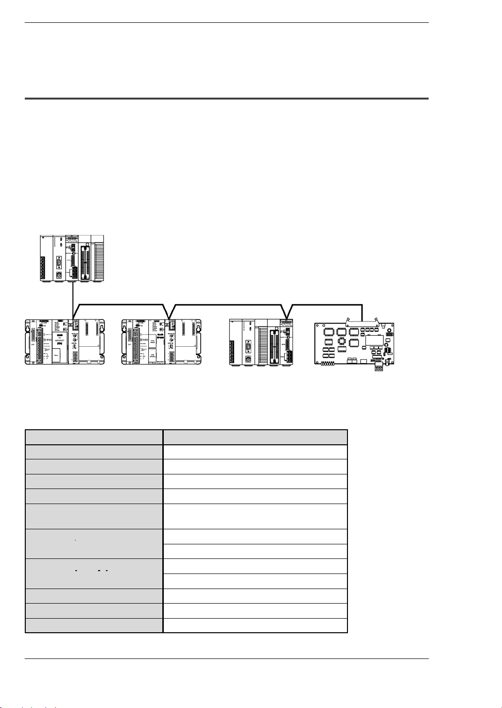
1.1.1 MEWNET-W Mode
A system can be configured economically between programmable controllers,
using twisted pair cables.
Link communication can be carried out between various programmable controllers, using link relays and link registers.
Communication is possible with conventional FP series devices capable of using the
MEWNET-W.
Thelinkrelaysand link registersusedforPCLinkcommunicationarespecifiedusingthe
system register.
FP2 Multi-wire link unit
(W mode)
Twisted pair cable
FP3 and
MEWNET-W
type link unit
FP10SH and
MEWNET-W type
link unit
Specifications
Item Description
Communication method
Transmission method
Communication path
Transmission distance
Transmission speed
(Baud rate)
Functions/number of
stations
PC link capacity per one
unit
Other functions
Interface
R.A.S. function
Token bus
Baseband transmission
Twisted pair cable
Total length: 800 m/2,625 ft.
500 kbps
PC link function: max. 16 stations
Data transfer function: max. 32 stations
Link relay: 1,024 points
Link register: 128 words
Remote programming
Conforming to RS485
Hardware self-diagnostic function
FP2 Multi-wire link
unit (W mode)
FP-C and
MEWNET-W type
link board
1-4

General SpecificationsFP2 Multi-wire Link Unit
/
py
p
1.1 How the Multi-wire Link Unit Works
1.1.2 MEWNET-W2 Mode
Large volumes of data can now be transmitted over long distances.
Linkcommunication can becarried out betweenvariousFP2units, using linkrelays and
link registers.
Communication limited to only FP2 units is possible.
Using the MEWNET-W mode increases the volume of data that can be handled.
UsingtheMEWNET-Wmodeextendsthetransmissiondistance(whensetto250kbps).
Thelinkrelay and link registerareasusedfor PC link communicationarespecifiedusing
user programs.
FP2 Multi-wire link
unit (W2 mode)
Twisted pair cable
FP2 Multi-wire link
unit (W2 mode)
Specifications
Item Description
Communication method
Transmission method
Communication path
Transmission at 250 kbps
distance
Transmission speed
(Baud rate)
Functions/number of
stations
PC link capacity per one
unit
Other functions
Interface
R.A.S. function
at 500 kbps
Token bus
Baseband transmission
Twisted pair cable
Total length: 1200 m/3,937 ft.
Total length: 800 m/2,625 ft.
500 kbps or 250 kbps
PC link function: max. 32 stations
Data transfer function: max. 32 stations
Link relay: 4,096 points
Link register: 4,096 words
Remote programming
Conforming to RS485
Hardware self-diagnostic function
FP2 Multi-wire link
unit (W2 mode)
.
Note
When using the PC Link in the MEWNET-W2 mode, the default
settings must be obtained from the user program.
1-5
General Specifications FP2 Multi-wire Link Unit
1.1 How the Multi-wire Link Unit Works
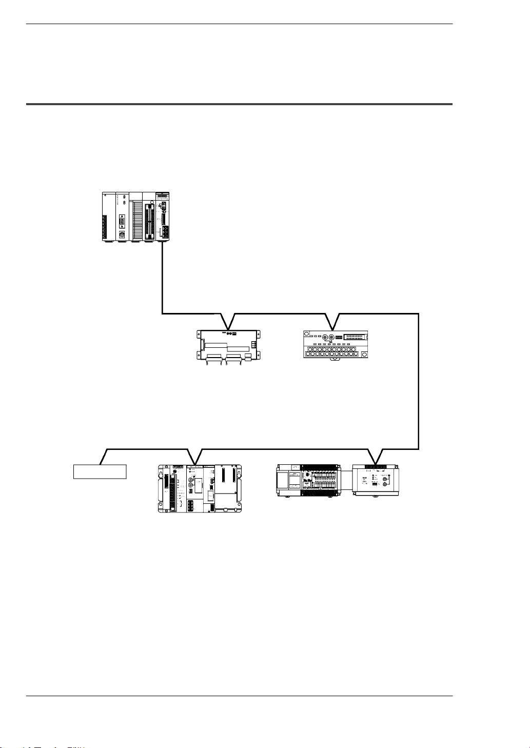
1.1.3 MEWNET-F Mode
Dual-core cables reduce the amount of wiring in the remote I/O system.
Remote I/O control is possible, using the FP2 as the master station.
Communicationwithconventionalslavestationsispossible,usingtheFP2asthemaster
station.
FP2 Multi-wire link unit
(F mode)
Master station
Slave station
Commercially
available manifold
solenoid valve
Twisted pair cable/VCTF
I/O terminal board
FP3 MEWNET-F
(remote I/O) slave unit
cable
I/O terminal unit
FP1 I/O link unit
FP0 and FP-M can also be connected
using slave station units or boards.
1-6

Specifications
Item Description
Communication method
Synchronization method
Communication path
Transmission distance
Transmission speed
(Baud rate)
Number of slave stations
Controllable I/O points
Interface
Transmission error check
Note
.
Two-line, half-duplex transmission
Start-stop synchronous system
Twisted pair cable or VCTF cable
Total distance: max. 700 m/2,296.59 ft
500 kbps
Max. 32 stations
Max. 2,048 points
Conforming to RS485
CRC (Cyclic Redundancy Check) method
The user should avoid mixing different types of transmission
cables in a single network. The same type of transmission cable
should be used throughout the network.
General SpecificationsFP2 Multi-wire Link Unit
1.1 How the Multi-wire Link Unit Works
1-7

General Specifications FP2 Multi-wire Link Unit
1.2 Specifications
1.2 Specifications
1.2.1 General Specifications
Item Descriptions
Ambient temperature
Storage temperature
Ambient humidity
Storage humidity
Breakdown voltage
Insulation resistance
Vibration resistance
Shock resistance
Noise immunity
Operating conditions
Current consumption
Weight
0to55qC/32 to 131qF
-20 to +70qC/-4 to +158qF
30 to 85 % RH (non-condensing)
30 to 85 % RH (non-condensing)
500 V AC, 1 minute between external terminal and frame
ground terminal
100 MΩor more (measured with a 500 V DC megger testing)
between external terminal and frame ground terminal
10 to 55 Hz, 1 cycle/min: double amplitude of 0.75 mm/
0.030 in., 10 min on 3 axes
98 m/s2or more, 4 times on 3 axes
1,000 Vp-p with pulse widths 50 ns and 1μs
(based on in-house measurements)
Free from corrosive gases and excessive dust
220 mA or less (at 5 V DC) (*Note)
pprox.
A
110 g/3.880 oz
.
1-8
Note
For information concerning restrictions on current consumption,
refer to section 1.4.1.

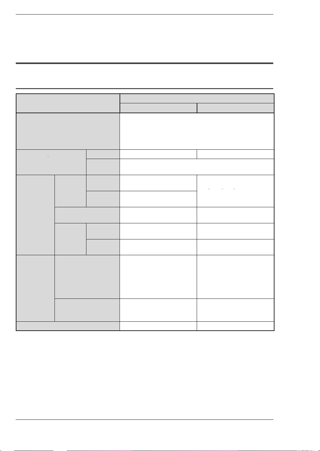
1.2.2 Transmission Specifications
General SpecificationsFP2 Multi-wire Link Unit
1.2 Specifications
Item
Communication method
Transmissionmethod
Transmissionspeed
(Baud rate)
Transmissiondistance
(*section 1.2.4)
Number of slave stations
Error check method
Synchronized method
Interface
Communication path
RAS function
Descriptions
W mode W2 mode F mode
Token bus method Polling method
Baseband transmission method
500kbps 500kbps/250kbps 500kbps
Overall distance:
max. 800m/2,625
ft.
Max. 32 stations One master unit
CRC (Cyclic Redundancy Check) method
Start-stop synchronous system
Conforming to RS485
Twisted pair cable Twisted pair cable,
Hardware self-diagnostic function
Overall distance:
max.
1200m/3,937 ft.
(at 250 kbps)
800m/2,625 ft.
(at 500 kbps)
Overall distance:
max.
700m/2,296.58 ft.
and max. 32 slave
stations
VCTF cable
1-9
General Specifications FP2 Multi-wire Link Unit
/
,,,
1.2 Specifications
1.2.3 Performance Specifications
1.2.3.1 W and W2 Modes
Item
Communication functions
Functions/number of PC link
stations
PC link Area of
use
Setting method
Capacity Link
Movement
status/
error alert
Data transfer capacity
Area of use
Setting method
Other
functions
Link
relays
Link
registers
relays
Link
registers
Specification
W mode W2 mode
PC link
Computer link
Data transfer
Remote programming
Hierarchical link
Max. 16 stations Max. 32 stations
Max. 32 stations
Fixed at WL Set by selecting among
WL, WR, LD, DT and FL.
Fixed at LD
Specified using system
register.
Max. 1,024 points Max. 4,096 points (*Note)
Max. 128 words Max. 4,096 words (*Note)
Special internal relays
Special data registers
— Specified using
Max. 16 words Max. 1,020 words
(*Note)
Specified using user
program.
Special internal relays
Special data registers
Detailed information is
output to WL, WR, LD,
DT, or FL, depending on
the setting.
F145
(SEND)/P145 (PSEND)
instruction.
.
1-10
Note
Use a program to keep WL, WR, LD, DT and FL settings within the
PC link capacity.

1.2.3.2 F Mode
Item Specification
Controllable points per one CPU
Controllable points per one unit
Controllable slots per one CPU
Controllable slots per one unit
Controllable master units per one CPU
Max. 2,048 points
Max. 2,048 points
Max. 128 slots
Max. 64 slots
Max. 4 units
General SpecificationsFP2 Multi-wire Link Unit
1.2 Specifications
1-11
General Specifications FP2 Multi-wire Link Unit
p
cable
ft
2,625
ft.2,625
ft.3,937
ft.(
/
(*Note2)
Fig.1
Coinduc
700m/
700m/
1
100m/
ft
,
,
,
(
/
(*Note2)
,
656.17
ft.)
(
ote
)
1.2 Specifications
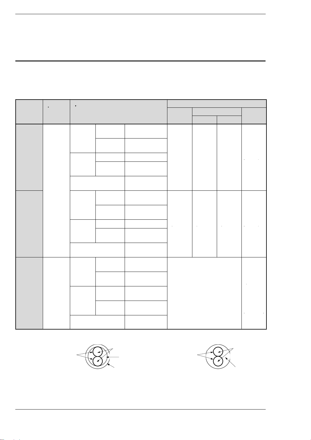
1.2.4 Transmission Cable Specifications
The user should avoid mixing different types of transmission cables in a single network.
The same type of transmission cable should be used throughout the network.
Table of cables
Transmission
Shielded
twisted
pair
cable
Shielded
twisted
pair cable
VCTF
cable
(*Note 3)
Sectional
view
Fig.1
below
Fig. 2
below
Specification
Conductor
Insulator Material Polyethylene
Cable diameter Approx. 8.5 mm/
Coinductor
Insulator
Cable diameter Approx. 7.8 mm/
Condiuctor
Insulator Material Polyvinyl choride
Cable diameter Approx. 6.6 mm/
Size Min. 1.25 mm
Resistance Max. 16.8Ω/km
Thickness Max. 0.5 mm/
Size Min. 0.5 mm
Resistance Max. 33.4Ω/km
Material Polyethylene
Thickness Max. 0.5 mm/
Size Min. 0.75 mm
Resistance Max. 25.1Ω/km
Thickness Max. 0.6 mm/
(AWG16 or more)
(at 20qC/ 68qF)
0.020 in.
0.335 in.
(AWG20 or more)
(at 20qC/68qF)
0.020 in.
0.307 in.
(AWG18 or more)
(at 20qC/68qF)
(*Note 1)
0.024 in.
0.260 in.
2
2
2
Guaranteed transmission distance
W mode W2 mode F mode
500kbps 250kbps
700 m/
2,296.59
800 m/
2,296.59
ft.
800 m/
2,296.59
ft.
Not available
1200 m/
3,617.24
ft.
.
(300 m/
984.25 ft.)
*
600 m/
1,968.50
.
(300 m/
984.25 ft.)
*
400 m/
1,312.34
ft.
(200 m/
(*Note 2)
Sectional view of cable
Insulator
Fig. 1
1-12
Conductor
Shield
Jacket
Shielded twisted pair cable
Insulator
Fig. 2
Conductor
VCTF cable
next page
.
Jacket
.
Notes
General SpecificationsFP2 Multi-wire Link Unit
1.2 Specifications
(*1):Because polyvinyl chloride has poorer electrical character-
D
istics than polyethylene, the overall transmission distance
is shorter.
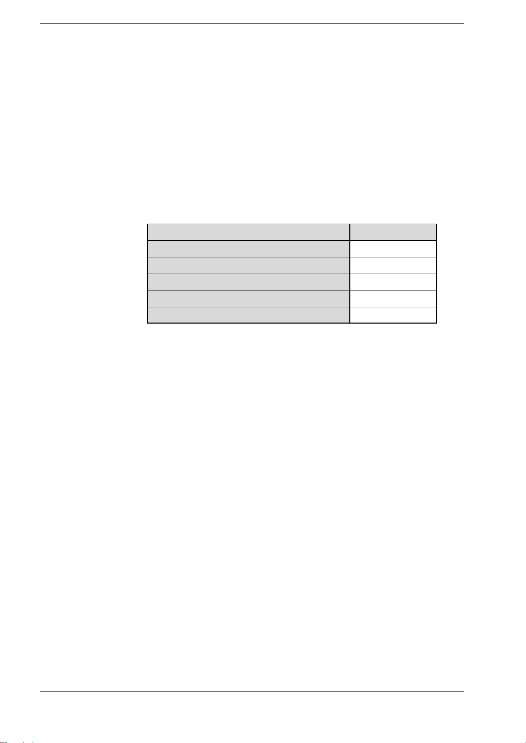
(*2):If products with the order numbers listed below are in-
D
cluded in the network when the F mode is used, the maximum transmission distance is the distance noted in parentheses. Information on the various types of commercially
available manifold solenoid valves should be confirmed
with the manufacturing company.
Product name Order number
12 V DC type I/O terminal board
24 V DC type I/O terminal board
FP3 remote I/O slave unit
FP5 remote I/O slave unit
Manifold solenoid valve
AFP87441
AFP87442
AFP3741
AFP5741
—————
(*3):If transmission is adversely affected by noise in the envi-
D
ronment, shielded twisted pair cables should be used.
1-13
 Loading...