

Panasonic FP2 ET-LAN, FP2-ET1, FP2-ET2, AFP27901, AFP2790 Technical Manual

PROGRAMMABLE CONTROLLER
FP2 ET-LAN Unit
Technical Manual
[Applicable Model]
・
FP2-ET1 (Model No. AFP2790) (Discontinued product)
・
FP2-ET2 (Model No. AFP27901)
ARCT1F322E-7
2013.12
panasonic.net/id/pidsx/global

Safety Precautions
Observe the following notices to ensure personal safety or to prevent accidents.
To ensure that you use this product correctly, read this User’s Manual thoroughly before use.
Make sure that you fully understand the product and information on safety.
This manual uses two safety flags to indicate different levels of danger.
WARNING
If critical situations that could lead to user’s death or serious inj ury is assumed by
mishandling of t he product.
-Always take precautions to ensure the overall safety of your system, so that the whole
system remains safe in the event of failure of this product or other external factor.
-Do not use this product in areas with inflammable gas. It could lead to an explosion.
-Exposing this product to excessive heat or open flames could cause damage to the lithium
battery or other electronic parts.
CAUTION
If critical situations that could lead to user’s injury or only pr opert y damage is
assumed by mishandling of the prod uc t .
-To prevent excessive exothermic heat or smoke generation, use this product at the values
less than the maximum of the characteristics and performance that are assured in these
specifications.
-Do not dismantle or remodel the product. It could cause excessive exothermic heat or smoke
generation.
-Do not touch the terminal while turning on electricity. It could lead to an electric shock.
-Use the external devices to function the emergency stop and interlock circuit.
-Connect the wires or connectors securely.
The loose connection could cause excessive exothermic heat or smoke generation.
-Do not allow foreign matters such as liquid, flammable materials, metals to go into the inside
of the product. It could cause excessive exothermic heat or smoke generation.
-Do not undertake construction (such as connection and disconnection) while the power
supply is on. It could lead to an electric shock.
Copyright / Trademarks
-This manual and its contents are copyrighted.
-You may not copy this manual, in whole or part, without written consent of
Industrial Devices SUNX Co., Ltd.
-Windows is a registered trademark of Microsoft Corporation in the U n ite d States and other
countries.
-Ethernet is a registered trademark of Fuji Zerox Co., Ltd. And XeroxCorp.
-All other company names and product names are trademarks or registered trademarks of
their respective owners.
Panasonic
PLC_ORG_ET

Table of Contents
Compatibility with the FP3
Difference between AFP2790 and AFP27901
1. Unit Functions and Restrictions ............................................................ 1-1
1.1 Features and Structure of ET-LAN Unit......................................................................... 1-2
1.1.1 Features ...................................................................................................................... 1-2
1.1.2 Unit Type ..................................................................................................................... 1-3
1.1.3 Structure of Network ................................................................................................... 1-3
1.1.4 Connecting to a Network ............................................................................................. 1-4
1.1.5 Connections Between Networks ................................................................................. 1-6
1.2 Overview of ET-LAN Unit Functions .............................................................................. 1-7
1.2.1 Function Model ............................................................................................................ 1-7
1.2.2 Communication Functions .......................................................................................... 1-8
1.2.3 Self Diagnosis Functions .......................................................................................... 1-10
1.3 Restrictions on Units Combination ............................................................................. 1-11
1.3.1 Restrictions on Current Consumption ....................................................................... 1-11
1.3.2 Restrictions on Installation Position .......................................................................... 1-11
1.3.3 Restrictions on Number of Units that can be Installed .............................................. 1-12
1.4 Restrictions on Unit Version and Func tions .............................................................. 1-12
1.4.1 Functions of ET-LAN Unit and Applicable Versions ................................................. 1-12
1.4.2 Precautions when using the e-mail function ............................................................. 1-12
1.5 Unit Version and Communication Setting Method ..................................................... 1-13
1.5.1 Configurator ET ......................................................................................................... 1-13
1.6 Restrictions Relating to Communication Conditions and Functions ...................... 1-13
1.6.1 Precautions When Using the FP2 CPU Unit ............................................................. 1-13
2. Names and Functions of Parts .............................................................. 2-1
2.1 Names and Functions of Parts ....................................................................................... 2-2
2.1.1 Names and Functions of Parts .................................................................................... 2-2
2.1.2 Operating Status LEDs ............................................................................................... 2-3
2.1.3 Mode Setting Switch ................................................................................................... 2-3
2.2 Connector Pin Layout ..................................................................................................... 2-4
2.2.1 10BASE5(AUI) Connector (with D-SUB 15 pins retainer) .......................................... 2-4
2.2.2 100BASE-TX/10BASE-T Connector (RJ45) ............................................................... 2-4
2.2.3 External Power Supply Terminal for 10BASE5 (12 V DC).......................................... 2-4
3. Connection for LAN Cable ..................................................................... 3-1
3.1 Precautions Concerning Insta llation ............................................................................. 3-2
i

3.2 Connection for LAN Cable .............................................................................................. 3-4
3.2.1 100BASE-TX and 10BASE-T Connections ................................................................. 3-4
3.2.2 10BASE5 (AUI) Connections ...................................................................................... 3-5
3.3 Test Mode ......................................................................................................................... 3-6
3.3.1 Types and Contents of Test Modes ............................................................................ 3-6
3.3.2 Running Test Modes ................................................................................................... 3-7
4. Confirming the Design Contents ........................................................... 4-1
4.1 Address Confirmation ..................................................................................................... 4-2
4.1.1 IP Address Confirmation ............................................................................................. 4-2
4.1.2 MEWTOCOL Station Number Confirmation ............................................................... 4-2
4.2 I/O Allocations .................................................................................................................. 4-3
4.2.1 Confirmation of I/O Allocations ................................................................................... 4-3
4.2.2 Confirmation of Route Numbers ................................................................................. 4-4
4.3 Confirmation of the Contents of the Sh ared Memory .................................................. 4-5
4.3.1 Configuration of the Shared Memory .......................................................................... 4-5
4.3.2 The Roles Played by the Various Areas ..................................................................... 4-6
4.4 Handshake Method .......................................................................................................... 4-8
4.4.1 Handshake Method ..................................................................................................... 4-8
4.4.2 Using the I/O for the Handshake ................................................................................. 4-9
4.4.3 Using the Shared Memory for the Handshake .......................................................... 4-10
5. Initialization Processing and Termination Processing ........................ 5-1
5.1 Initialization/Termination Processing ............................................................................ 5-2
5.1.1 What is Initializaiton Processing? ............................................................................... 5-2
5.2 Processing Procedures ................................................................................................... 5-4
5.2.1 An Overview of the Initialization Process ing Procedure ............................................. 5-4
5.2.2 An Overview of the Termination Processing Procedure ............................................. 5-5
5.2.3 Writing Data to the Initialization Information Setting Area .......................................... 5-6
5.2.4 Writing Data to the Routing Information Setting Area ............................................... 5-12
5.3 Reading Initialization Information ................................................................................ 5-17
5.4 Sample Program ............................................................................................................ 5-19
6. Open Processing and Close Processing .............................................. 6-1
6.1 Open/Close Processing .................................................................................................. 6-2
6.1.1 What is Open Processing?.......................................................................................... 6-2
6.1.2 Types of Open Processing .......................................................................................... 6-4
6.2 Processing Procedures ................................................................................................... 6-7
6.2.1 An Overview of the Open Processing Procedure ....................................................... 6-7
ii

6.2.2 An Overview of the Close Processing Procedure ....................................................... 6-8
6.2.3 Writing Data to the Connection Information Setting Area ........................................... 6-9
6.3 Reading Connection Information ................................................................................. 6-12
7. Computer Link Function ........................................................................ 7-1
7.1 An Overview of the Computer Link Function ............................................................... 7-2
7.1.1 What is the Computer Link Function? ......................................................................... 7-2
7.1.2 Commands and Functions Available for Use .............................................................. 7-3
7.2 Computer Link Procedure .............................................................................................. 7-5
7.3 Settings on the PLC Side ................................................................................................ 7-6
7.3.1 Connection Information Settings ................................................................................. 7-6
7.3.2 Writing to the Shared Memory .................................................................................... 7-8
7.3.3 Sample Program ......................................................................................................... 7-9
7.4 Command Communication on the Computer Side .................................................... 7-11
7.4.1 Communication Data Format (1) ............................................................................... 7-11
7.4.2 Communication Data Format (2) ............................................................................... 7-14
8. Data Transfer Function ........................................................................... 8-1
8.1 An Overview of the Data Transfer F u n ction ................................................................. 8-2
8.1.1 What is the Data Transfer Function? .......................................................................... 8-2
8.1.2 Commands and Functions that can be Used .............................................................. 8-3
8.2 Data Transfer Procedure ................................................................................................. 8-4
8.3 Settings on the PLC Side ................................................................................................ 8-5
8.3.1 Connection Information Settings ................................................................................. 8-5
8.3.2 Writing to the Shared Memory .................................................................................... 8-7
8.3.3 Sample Program ......................................................................................................... 8-8
8.4 Command Communication on the Computer Side .................................................... 8-10
8.4.1 Communication Data Format (1) ............................................................................... 8-10
8.4.2 Communication Data Format (2) ............................................................................... 8-13
8.4.3 Communication Data Format (3) ............................................................................... 8-16
9. Transparent Communication Function ................................................. 9-1
9.1 An Overview of the Transparent Communication Function........................................ 9-2
9.1.1 What is the Transparent Communication Function? ................................................... 9-2
9.2 Transparent Communication Proc edures ..................................................................... 9-3
9.3 Settings on the PLC Side ................................................................................................ 9-4
9.3.1 Connection Information Settings ................................................................................. 9-4
9.3.2 Writing to the Shared Memory .................................................................................... 9-5
iii

9.4 Communication Processing for Transparent Communication ................................... 9-6
9.4.1 Connection Processing Procedure ............................................................................. 9-6
9.4.2 Procedure for Transmission Processing ..................................................................... 9-8
9.4.3 Procedure for Reception Processing ........................................................................ 9-10
9.4.4 Handshake Signal and Data Area ............................................................................. 9-13
9.5 Sample Program ............................................................................................................ 9-16
9.5.1 Sample Program <Initialization to Open> ................................................................. 9-16
9.5.2 Sample Program <Transmission Processing and Reception Processing> .............. 9-18
9.5.3 Sample Program <Reception to Transmission> ....................................................... 9-21
10. Auto Connection ................................................................................. 10-1
10.1 Auto Connection Function.......................................................................................... 10-2
10.1.1 Reading Auto Connection Status Information ......................................................... 10-5
10.1.2 Auto Initialization Proc ess ing .................................................................................. 10-6
10.1.3 Auto Open Processing ............................................................................................ 10-7
10.1.4 Auto Connection Information Settings .................................................................... 10-8
10.1.5 Reading Auto Connection Information .................................................................... 10-9
10.1.6 Sample Program ................................................................................................... 10-11
10.2 System Connection ................................................................................................... 10-23
10.2.1 Initialization processing in the system connection ................................................ 10-23
10.2.2 Open processing in the system connection .......................................................... 10-23
10.2.3 System Connection Information Setting ................................................................ 10-24
10.2.4 Reading system connection information settings ................................................. 10-26
11. E-mail Function ................................................................................... 11-1
11.1 Outline of E-mail Function .......................................................................................... 11-2
11.1.1 E-mail Function Specification .................................................................................. 11-2
11.2 Precautions When Using the E-mail Functio n .......................................................... 11-3
11.3 Operation Environment ............................................................................................... 11-5
11.4 Sending/Receiving E-mails Using E-mail Function ................................................. 11-6
11.5 E-mail Function ............................................................................................................ 11-7
11.6 Security in Receiving E-mails .................................................................................. 11-10
11.7 Outline of Request E-mail Function ......................................................................... 11-12
11.7.1 Request Mail Format ............................................................................................. 11-13
11.8 Sending E-mail Using the Ladder Program ............................................................ 11-15
11.8.1 E-mail Send Processing Using the Ladder Program ............................................ 11-15
11.8.2 Ladder Send E-mail Settings ................................................................................ 11-17
11.8.3 Sample Program (for sending e-mails) ................................................................. 11-18
11.9 Receiving E-mails using the Ladder Program ........................................................ 11-19
iv

11.9.1 Sample Program (for receiving e-mails) ............................................................... 11-21
11.10 E-mail Error Log and E-mail Log Functions ......................................................... 11-22
11.10.1 What are the e-mail error logs and e-mail log functions ..................................... 11-22
11.10.2 Reading E-mail Error Log ................................................................................... 11-23
11.10.3 Reading E-mail logs ............................................................................................ 11-25
11.10.4 E-mail Status Area .............................................................................................. 11-27
11.10.5 Sample Program ................................................................................................. 11-28
11.11 Troubleshooting Flowchart .................................................................................... 11-31
12. Error Log Function ............................................................................. 12-1
12.1 Configuration of the Error Log Area .......................................................................... 12-2
12.1.1 What is the Error Log Function? ............................................................................. 12-2
12.1.2 Contents of Error Log Area ..................................................................................... 12-4
12.2 Reading the Error Log ................................................................................................. 12-5
12.2.1 Procedure for Reading the Error Log ...................................................................... 12-5
12.2.2 Sample Program ..................................................................................................... 12-6
12.3 Error Code Contents ................................................................................................... 12-7
12.3.1 Access Error ............................................................................................................ 12-7
12.3.2 System Error ......................................................................................................... 12-12
12.3.3 Warning Error ........................................................................................................ 12-12
12.3.4 Recovery Possible Error ....................................................................................... 12-13
12.3.5 E-mail Send Error.................................................................................................. 12-15
12.3.6 E-mail Receive Error transmission ........................................................................ 12-16
12.3.7 MEWTOCOL Error ................................................................................................ 12-17
12.3.8 Hardware Error ...................................................................................................... 12-17
12.3.9 Auto Connection Error .......................................................................................... 12-18
13. Troubleshooting.................................................................................. 13-1
13.1 Operation If an Error Occurs ...................................................................................... 13-2
13.1.1 Operation If the ALARM LED on the ET-LAN Unit Lights ....................................... 13-2
13.1.2 Operation If the “E1” or “E2” LED on the ET-LAN Unit Lights or Flashes .............. 13-3
13.2 What to Do If an Error Occurs .................................................................................... 13-4
13.2.1 If the Alarm "ALM" LED Lights on the ET-LAN Unit ................................................ 13-4
13.2.2 If the "E1" LED on the ET-LAN Unit Lights or Flahses ........................................... 13-4
13.2.3 If the “E2” LED on the ET-LAN Unit Lights or Flashes ........................................... 13-4
13.2.4 Troubleshooting Flowchart ...................................................................................... 13-6
13.3 Reset Function ............................................................................................................. 13-8
13.3.1 What is the Reset Function? ................................................................................... 13-8
13.3.2 No Communication Notification Function ................................................................ 13-8
13.3.3 Procedure of Reset Function .................................................................................. 13-9
13.3.4 Reset Function Sample Program .......................................................................... 13-10
v

14. MEWTOCOL Communication Procedure .......................................... 14-1
14.1 MEWTOCOL-COM (Computer Link) ........................................................................... 14-2
14.1.1 Overview of MEWTOCOL-COM ............................................................................. 14-2
14.1.2 Single Frames and Multiple Frames ....................................................................... 14-6
14.1.3 List of MEWTOCOL-COM Commands ................................................................... 14-8
14.2 MEWTOCOL-DAT (Data Transfer) ............................................................................ 14-25
14.2.1 Overview of MEWTOCOL-DAT ............................................................................ 14-25
14.2.2 List of MEWTOCOL-DAT Commands .................................................................. 14-27
14.3 MEWTOCOL Error Codes.......................................................................................... 14-31
14.3.1 Table of Error Code ............................................................................................... 14-31
15. Specifications ...................................................................................... 15-1
15.1 Tables of Performance Specifications ...................................................................... 15-2
15.1.1 General Specifications ............................................................................................ 15-2
15.1.2 Performance Specifications .................................................................................... 15-2
15.1.3 Communication Specifications ................................................................................ 15-3
15.2 I/O Allocation ................................................................................................................ 15-4
15.3 Table of Shared Memory ............................................................................................. 15-5
15.4 Table of Related Relays, Registers and Instructions ............................................. 15-25
15.4.1 System Register .................................................................................................... 15-25
15.4.2 Special Internal Relay ........................................................................................... 15-26
15.4.3 System Register .................................................................................................... 15-27
15.5 Minimum Transmission Delay Time ........................................................................ 15-28
15.6 ASCII Codes ............................................................................................................... 15-30
15.7 Dimensions ................................................................................................................ 15-31
16. Sample Program ................................................................................. 16-1
16.1 Sample Program .......................................................................................................... 16-2
16.1.1 An Overview of the Sample Program ...................................................................... 16-2
16.1.2 Workstation Sample Program ................................................................................. 16-3
16.1.3 Communication Setting Program on PLC Side ....................................................... 16-8
vi

(See page 1-4.)
1. 100BASE-TX/10BASE-T and 10BASE5 switch
4. Test mode operation selection
1. Test mode operation selection
4. Normal mode/test mode switch
Mounting
and 1-12.)
The following quantities can be inserted in any of
With the FP2SH CPU unit: 8 units
The mode setting switch is used to switch
memory handshaking.
(bank 0: 366H)
Connection data notification block
(offset address C)
Modified: LED display during testing and error
Error codes added
during operation
used without modification.
Compatibility with the FP3
Differences with the FP3 ET-LAN unit
The main differences between the specifications and operation of the FP2 ET-LAN unit and the FP3 ETLAN unit are given in the table below. Refer to the reference page numbers given for each item for
details regarding specifications and operation.
Item FP2 ET-LAN unit FP3 ET-LAN unit
Communication
interface
100BASE-TX, 10BASE-T, and 10BASE5 10BASE5
Mode setting
switch
(See page 2-3.)
position/qty.
limits
(See page 1-11
Handshaking
(See page 4-8.)
Handshake
signals
(See pages 4-9
to 4-12.)
Shared memory
(See page 15-5.)
Test mode
(See page 3-6.)
2. Reserved
3. Normal mode/test mode switch
the master backplane slots (including Multi-wiring
link unit MEWNET-W2 mode)
With the FP2 CPU unit: 3 units
I/O handshaking and shared-memory handshaking
can be used simultaneously.
I/O handshaking signals
Deleted: I/O handshake mode flag (XE)
Shared memory handshake signal
Deleted: I/O handshake mode flag
(bank 0: 360H bit E)
Added: Expansion complete signal area 2
(bank 0: 2E0H to 35FH)
Added: Receive processing complete code
(offset address A)
Receive unnotified data size
(offset address B)
Receive unnotified data size copy
Test items
1. Mode setting switch test
2. LED test
3. ROM test
4. RAM test
5. Shared memory test
6. Timer test
7. Internal loopback test
8. External loopback test
Added: Mode setting switch test
Deleted: EEPROM checksum test
2. Handshake mode selection
3. ONLINE/OFF L INE switch
The following quantities can be inserted
in any of the master backplane slots
(including MEWNET-H link unit)
FP3/FP10SH CPU unit: 3 units
between I/O handshaking and shared
-
-
Test items
1. LED test
2. ROM test
3. RAM test
4. Shared memory test
5. EEPROM checksum test
6. Timer test
7. Internal loopback test
8. External loopback test
8036H: MEWTOCOL transmission error
Error log
(See page 12-7.)
Ladder program
vii
Error codes deleted
8006H: OFFLINE error
8009H: Mode change error
8019H: Forced close error
B001H/B002H: ONLINE/OFFLINE switching error
Ladder programs created using the FP3 can be
-
-

100BASE-TX
10BASE-T
10BASE5
AFP2790
Available
Available
Available
AFP27901
Available
Available
Not available
Difference between AFP2790 and AFP27901
Available communication functions vary between AFP2790 and AFP27901.
Note) AFP27901 has no 10BASE5 connector.
Other functions are common.
viii

Chapter 1
Unit Functions and Restrictions
100BASE-TX
10BASE-T
10BASE5
AFP27901
Available
Available
Not available
1.1 Features and Structure of ET-LAN Unit
1.1.1 Features
The FP2 ET-LAN unit is an Ethernet (100BASE-TX, 10BASE-T or 10BASE5) connection interface for
TCP/IP and UDP/IP for the FP2 and FP2SH series programmable controllers.
Supports both TCP/IP and UDP/IP
The ET-LAN supports both the TCP/IP and UDP/IP protocols, enabling communication with a broad
range of computers and other devices in a network.
Simultaneous communication possible among up to eigh t connected conne ct ions
Communication can be carried out among up to eight connections connected to the network using only a
single unit. This enables connection to multiple partner nodes.
Three types of communicati on interfa ces supported
Three types of Ethernet communication interfaces are supported (Usable interfaces vary according to
the models): 100BASE-TX, 10BASE-T, and 10BASE5. Any one of these interfaces may be used.
Automatic switching is possible between 100BASE-TX and 10BASE-T using an auto-negotiation function,
while a switch can be used to switch between 100BASE-TX/10BASE-T and 10BASE5.
AFP2790 Available Available Available
Easy-to-use MEWTOCOL communication and general-purpose transparent communication
supported
The MEWTOCOL communication function (computer linking and data transmission) that enables
communication between personal computers, workstations, and FP series programmable controllers is
supported, as well as the transparent communication function that enables communication between
general-purpose devices such as computers.
Easy communication set-up
Communication settings can be easily performed using the setting tool (Configurator ET).
Changing the mode setting switches enables the communication setting to be performed by a ladder
program.
Using the system connection enables easy connections with devices such as a programming tool
(FPWIN GR).
1-2
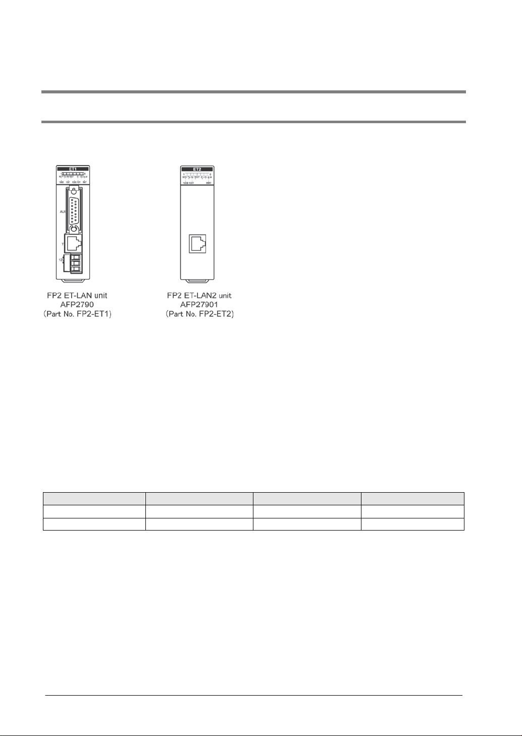
Name
Part No.
Model No.
FP2 ET-LAN2 unit
FP2-ET2
AFP27901
E-mail send and receive functions (for a standard equipment)
Sending e-mails
- Errors occurred in the programmable controller can be notified via e-mail.
- E-mails can be sent at the specified time.
- The devices of programmable controller are monitored and e-mails can be sent when the designated
conditions are satisfied.
Receiving e-mails
- Receiving an e-mail described in a specific format enables to notify the status of the programmable
controller via e-mail.
A broad range of self-diagnosis functions
- A function that checks the hardware and the communication status during operation.
- A function that checks the hardware and the communication status when the test mode is accessed.
- An error log function that records the results of various checks.
1.1.2 Unit Type
FP2 ET-LAN unit FP2-ET1 AFP2790
Note) No accessories such as connectors or cables are included.
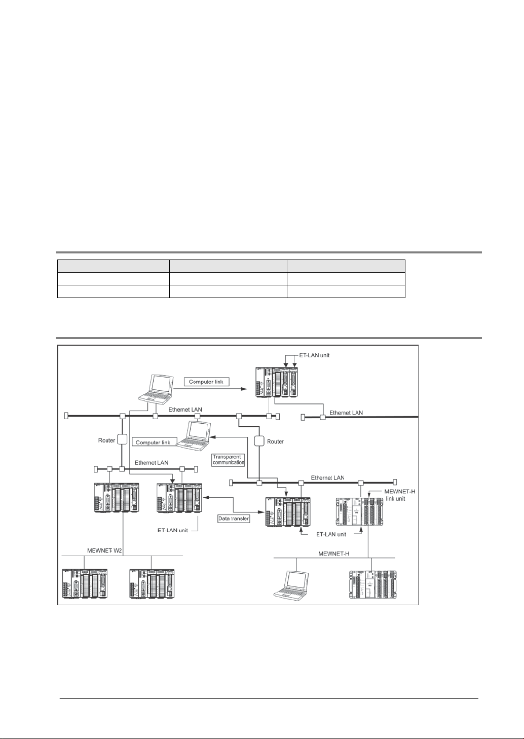
1.1.3 Structure of Network
Communication functions of ET-LAN unit
Using the ET-LAN unit to connect to an Ethernet (100BASE-TX, 10BASE-T, or 10BASE5) enables (1)
computer link function, (2) data transfer function, and (3) transparent communication function to be
carried out with other programmable controllers and computers connected to the network.
Combined use with a conventional MEWNET
The ET-LAN unit can be used in combination with another network unit such as the MEWNET-W/W2.
This makes it possible to connect an existing FA network to an Ethernet LAN, using MEWNET.
1-3
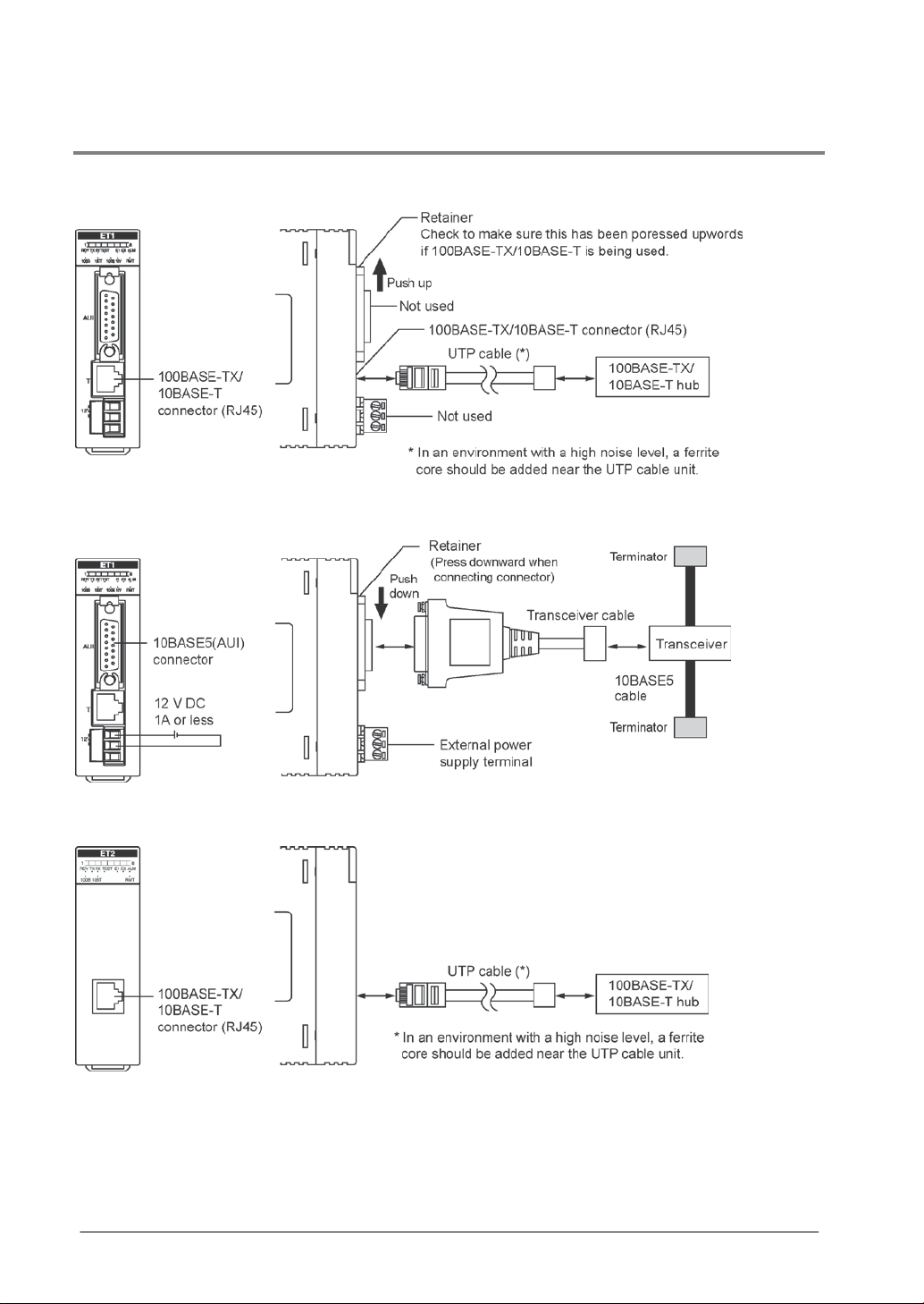
1.1.4 Connecting to a Network
AFP2790
100BASE-TX/10BASE-T
10BASE5 (AUI)
AFP27901
1-4

Item
100BASE-TX Note1)
10BASE-T Note1)
10BASE5
AFP27901
AFP27901
Transfer method
Base band
Base band
Base band
between nodes
length
Node spacing
- - Integer multiples of 2.5 m
Communication specifications
Target model
Data transfer 100M bits/s 10M bit/s 10M bit/s
Max. segment length 100 m Note2) 100 m Note2) 500 m
Max. distance
Communication cable
for connection
Max. transceiver cable
Max. number of nodes - - 100 nodes/segment
Note1) Switching between 100BASE-TX and 10BASE-T is done automatically by auto negotiation
function.
Note2) The standards cite 10 m as the maximum, but noise resistance measures such as attaching a
ferrite core may be necessary in some cases, depending on the usage environment. Also, if the
hub is positioned close to a control board, we recommend using it at a distance of 10 m or less.
Note3) The standards cite 50 m as the maximum, but noise resistance mea sures such as attaching a
ferrite core may be necessary in some cases, depending on the usage environment. Also, if the
transceiver is positioned close to a control board, we recommend using it at a distance of 5 m or
less.
AFP2790
205 m (2 segments) 500 m (5 segments) 2500 m (5 segments)
UTP (Category 5)
- - 50 m Note3)
AFP2790
UTP (Category 3, 4
and 5)
AFP2790
Transceiver cable
1-5
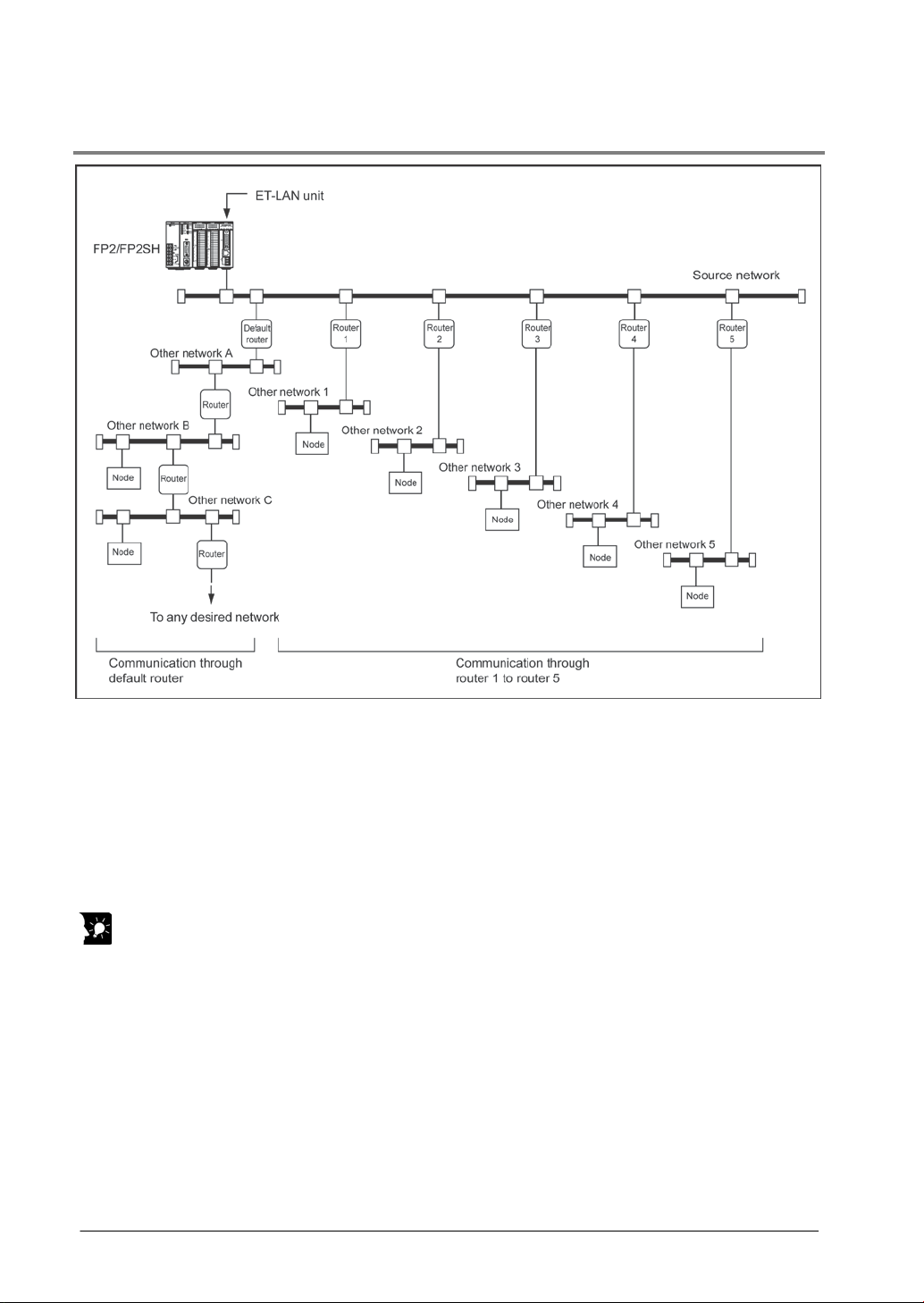
1.1.5 Connections Between Networks
With an Ethernet, communication is possible not only between the home network and a node, but also
between the nodes of other networks, using routers.
As shown in the illustration above, communication with nodes of other networks is classified as follows:
- The router is registered in advance, and communication is carried out between partner nodes of
adjacent networks (other networks 1, 2, 3, etc. in the above illustration)
- Communication is carried out with the partner nodes of networks other than those shown above (other
networks A, B, C, etc. in the above illustration)
Key Point:
When using the ET-LAN unit to carry out communication with partner nodes on another network, the
router used by the ET-LAN unit should be registered.
(1) Up to five routers can be registered for the source network, enabling communication with any of the
nodes on another adjacent network.
(See other networks 1, 2, 3 etc. in the left illustration.)
(2) Only a single default router can be registered, and communication carried out with any desired node
on any network other than those covered by (1), through the default router. (See other networks A,
B, C, etc. in the left illustration.)
The router may be one of the five routers specified at (1), or may be a different router.
1-6
1.2 Overview of ET-LAN Unit Functions
1.2.1 Function Model
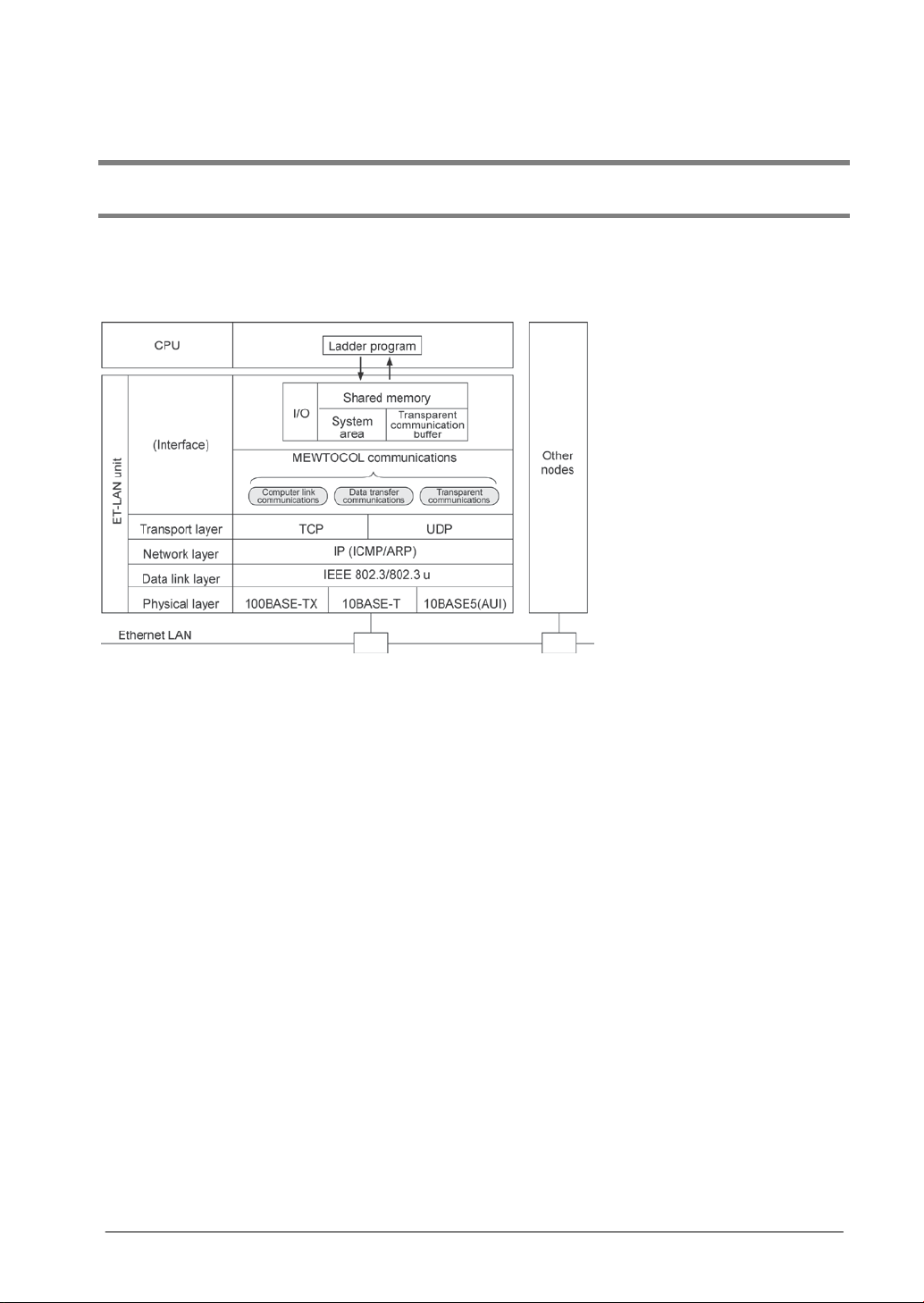
The functions of the ET-LAN unit are shown in the diagram below.
I/O and shared memory are used for the interface to the user progr a m (CPU unit) .
A maximum of eight simultaneous connections are possible for each of the computer link, data transfer,
and transparent communication functions.
The layers beneath the transport layer of the ET-LAN unit provide the following communication serv ic es.
TCP (Transmission Control Protocol):
TCP is a connection-base d co mmu nicat i on meth od which provides the virtual circuit. In the TCP
communication method, since communication services including re-transmission, sequence and flow
control for the communication data are provided, high communication reliability is guaranteed at the
protocol level.
UDP (User Datagram Protocol):
UDP is a connectionless communication method which provides only data communication in IP units. In
the UDP communication method, since no re-transmission, sequence, or flow control for the
communication data is provided, support at the application level is required to guarantee communication
reliability.
IP (Internet Protocol):
IP is used to transmit data in units of datagrams to partner node specified by an IP address. It provides
function such as the dividing and reassembling of communication data and communication services
between networks via a router.
ICMP (Internet Control Message Protocol):
ICMP is used to transmit the error message in the IP. The ET-LAN unit supports the echo replay option
only to the ping command.
ARP (Address Resolution Protocol):
ARP is used to transmit the Ethernet (physical) address, which is essential to Ethernet communications,
by specifying the IP address. When an ET -LAN unit accesses a station with unknown Ethernet address,
you only need to specify its IP address using the broadcast method.
AUI (Attachment Unit Interface
AUI is a transceiver cable that connects the ET-LAN unit with a transceiver.
1-7
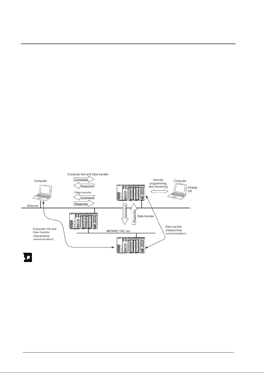
1.2.2 Communication Functions
MEWTOCOL Communication Function
There are two MEWTOCOL communication functions: a computer link function and a data transfer
function.
Computer link function: MEWTOCOL-COM (ASCII communication)
- Computer link communications can be realized by transmitting MEWTOCOL-COM data format from the
computer to the programmable controller.
- The computer can read from and write to the programmable controller’s I/O and registers.
- The maximum message length for one frame is 2k bytes.
- Using programming tools such as the FPWIN GR, remote programming and monitoring can be done
through a LAN circuit.
Data transfer function: MEWTOCOL-DAT (binary communication)
- Execution of the data transfer instructi on “F145 (SEND)/P145 (PSEND) and F!46 (RECV)/P146
(PRECV)” by a programmable controller program allows data transfer communications between
programmable controllers and between a programmable controller and a computer. Data
communication whereby the computer transfers the MEWTOCOL-DAT data format to the
programmable controller is als o possi ble.
- The computer can read from and write to the programmable controller’s I/O and registers. The
programmable controller can read from and write to the computer’s virtual I/O and virtual registers.
A programmable controller can read from and write to the I/O and registers of another programmable
controller partner node.
- The maximum amount of data that can be transferred by execution of one data transfer instruction is
1020 words.
Key Point:
- The programmable controller specifies the IP address and MEWTOCOL station number (1 to 64), and
opens a connection with its communication partner’s nod e using M EWTOCOL communication mode.
- When the programmable controller receives the MEWTOCOL command message, it returns a
response message automatically, so there is no need to describe a program to generate a response.
- With the MEWTOCOL communications function and the transparent communications function, you can
simultaneously use a maximum of eight connections with one ET-LAN unit.
The computer link function and data transfer function can be executed simultaneously using one
connection.
- Hierarchical communication via other MEWNET networks is also possible.
- When using the data transfer function, we recommend that you use TCP/IP to guarantee
communications reliability.
- When carrying out remote programming and monitoring, the ET-LAN unit settings should be set to the
MEWTOCOL communication mode and to TCP/IP communication, and the processing of the various
flags should be executed through a shared memory handshake.
1-8
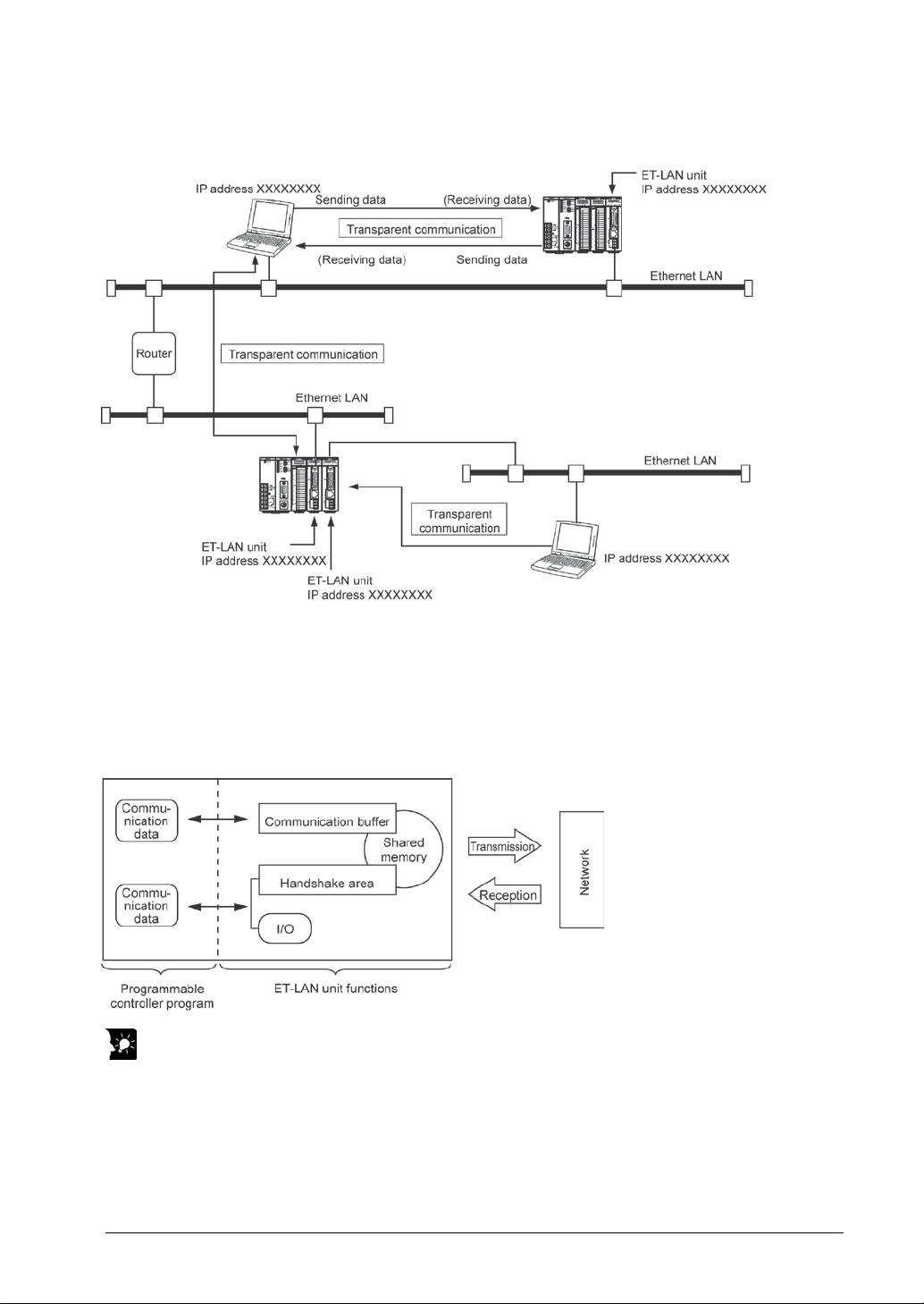
Transparent Communication Function
With the transparent communication function, transparent data transmission and reception between
computer and programmable controller and programmable controller and programmable controller is
possible.
Storage and extraction of the communication data at the programmable controller is carried out by
reading from and writing to the ET-LAN unit’s shared memory communication buffer. The communication
requests are performed by switching on and off bits in the I/O or shared memory handshake areas.
Key Point:
- With transparent communication, either the computer or programmable controller specifies the IP
address, and they open a mutual connection with the communication partner. After opening a
connection, communication processing on the programmable controller side is done by the ladder
program reading from and writing to the communication buffer of shared memory, and executing the
communication requests.
- With the transparent communication function and the MEWTOCOL communications function (computer
link and data transfer), you can simultaneously use a maximum of eight connections with one ET-LAN
unit.
1-9

1.2.3 Self Diagnosis Functions
Hardware and communication status check function
The ET-LAN unit is equipped with a self-diagnosis function that monitors the hardware (CPU unit and
memory) and the communication status during operation. You can check the self diagnosis results using
the LEDs on the unit, or by checking the contents of error log area in the shared memory.
Test mode operation function
The ET-LAN unit is reequipped with a test mode operation function for checking the hardware (memory
check and communications check) and for performing internal and external loop back tests. You can
check the results of the test mode operation function using the LEDs on the unit, or by checking the
contents of error log area in the shared memory.
Error log function
The ET-LAN unit is equipped with an error log function that records hardware and communications faults
in the order that they occur. You can read out the contents of error log from the error log area in the
shared memory.
1-10
Name
Part number
Model number
Current consumption (at 5 V DC)
FP2 ET-LAN2 unit
FP2-ET2
AFP27901
670 mA
1.3 Restrictions on Units Combination
1.3.1 Restrictions on Current Consumption
The internal current consumption (at 5 V DC power supply) for the FP2 ET-LAN unit is 670 mA. When
the system is configured, the other units being used should be taken into consideration, and a power
supply unit with a sufficient capacity should be used.
FP2 ET-LAN unit FP2-ET1 AFP2790 670 mA
Reference: For information on the internal current consumption of other units, see the
“FP2/FP2SH User's Manual” and the manuals provided with the other units.
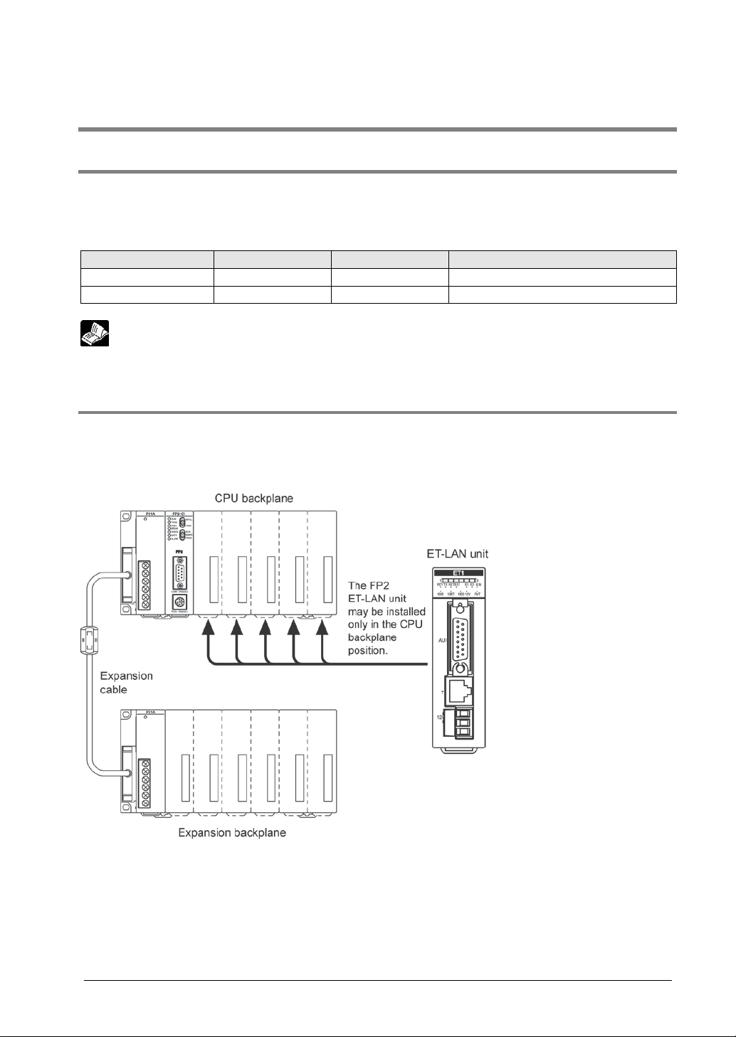
1.3.2 Restrictions on Insta llation Po sition
The FP2 ET-LAN unit may be installed only in the CPU backplane position. However, the units should be
installed to the right of the power supply unit and CPU unit. It cannot be installed in an expansion
backplane.
1-11

Restrictions on number of units
For FP2 CPU unit
For FP2SH CPU unit
Functions of ET-LAN Unit
Version of ET-LAN Unit
Version of CPU unit
Self-diagnosis function
Data transfer function
Transparent communication function
Error log function
System connection
E-mail function
1.3.3 Restrictions o n Numbe r of Unit s that can be Instal led
The following restrictions apply when installing the ET-LA N unit in a program mab le contr ol ler .
Unit name
ET-LAN unit
Multi-wire link unit
(MEWNET-W2 mode)
Note:
If the hierarchical link function is being used through the MEWNET and the communication path includes
an MEWNET-W, the maximum number of units that can be installed is two, for the units noted below.
- ET-LAN unit
- Multi-wire link unit
- Computer communication unit
Up to 3 units
(up to 2 units for link between PLCs)
Up to 8 units
(up to 2 units for link between PLCs)
1.4 Restrictions on Unit Version and Functions
The required versions of ET-LAN unit and CPU unit vary according to the used functions.
1.4.1 Functions of ET-LAN Unit and Applicabl e Vers ions
FP2 CPU unit
- MEWTOCOL-COM communication
- MEWTOCOL-DAT communication
Available with all the versions of
ET-LAN unit.
Ver. 1.08 or later
FP2SH CPU unit
Ver. 1.02 or later
Auto connection function
- Auto connection
-
1.4.2 Precautions when using the e-mail function
The calendar function is required for the CPU unit for using the e-mail function.
Add the following optional memory with the calendar function for using the FP2 CPU unit.
Expansion memory unit FP2-EM1 (AFP2201)
FP2-EM2(AFP2202)
It is not necessary to add the optional memory when using the FP2SH CPU unit as the calendar function
is built in the CPU unit.
Reference: <FP2/FP2SH User’s Manual (ARCT1F320)
2.3.1 Expansion Memory Unit/ROM <Option (FP2-EM)>
When there is no calendar function, the time to be recorded in e-mails is always the following time.
1 Jan. 2030 Tuesday 00:00:00 (Japan time)
- Indication: Date: Tue, 01 Jan 2030 00:00:00 +900
1-12
FP2-EM3(AFP2203)
Ver.2.00 or later of ET-LAN unit is
required.
FP2 CPU unit
Ver. 1.21 or later
FP2SH CPU unit
Ver. 1.10 or later

Version of ET-LAN Unit
Communication setting method
(Can be switched by the mode setting switches.)
Name
Required OS
Hard disk capacity
Model No.
Windows Vista
1.5 Unit Version and Communication Setting Me thod
Various communication settings such as IP address and communication method should be specified for
using the ET-LAN unit.
The setting method varies depending on the version of the used ET-LAN unit.
ET-LAN Unit Ver.1.00 or later Ladder program
ET-LAN Unit Ver.2.00 or later
1.5.1 Configurator ET
Configurator ET is an exclusive tool for setting the communication settings or e-mail function of the ETLAN unit.
Configuration ET can be used with Ver.2.00 or later of ET-LAN unit.
Japanese
Control Configurtor ET
English AFPS32510
Ladder program or Configurator ET
Windows95
(OSR2 or later)
Windows98
WindowsME
Windows2000
WindowsXP
20MB or later
AFPS32110
1.6 Restrictions Relati ng to Communication Conditions and Functions
1.6.1 Precautions When Using the FP2 CPU Unit
If the codes „MC, MD, MG“ for monitor commands are used among the commands sent from the host
computer, commands being sent from multiple computers will prevent data from being read and written
correctly.
Note:
If monitor commands are sent from multiple computers, registered data will overwrite previously
registered data, starting from the latest item, so that different data will end up being monitored.
Key Point:
- Monitor commands are used to execute monitoring after the contacts and data to be monitored have
been registered on the PLC side.
- If using the FP2SH CPU unit, the above restrictions apply for up to 10 connections.
1-13

1-14

Chapter 2
Names and Functions of Parts
2.1 Names and Functions of Parts
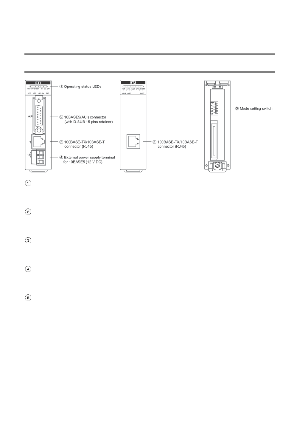
2.1.1 Names and Functions of Parts
Operating status LEDs
These display the operating status of the unit, such as connection and communication conditions, and
error statuses.
10BASE5(AUI) connector
When an Ethernet (10BASE5) is being used, this connector is used to connect the ET-LAN unit and the
transceiver, using a transceiver cable.
100BASE-TX/10BASE-T connector (RJ45)
When an Ethernet (100BASE-TX, 10BASE-T) is being used, this connector is used to connect the ETLAN unit and the hub, using a UTP cable.
External power supply terminal for 10BASE5 (12 V DC)
When an Ethernet (10BASE5) is being used, this terminal supplies power to the transceiver.
When an Ethernet (100BASE-TX, 10BASE-T) is being used, this terminal is not used.
Mode setting switch
These are used to select the communication interface and the test mode for the Ethernet.
2-2
LED
LED
1 1 Connection 1 connec ted
Connection 1 fault
Connection 1 not con nected
4 4 Connection 4 connec ted
Connection 4 fault
Connection 4 not connected
7 7 Connection 7 connec ted
Connection 7 fault
Connection 7 not connected
8 8 Connection 8 connec ted
Connection 8 fault
Connection 8 not c onnected
(communicati on ready status)
RX
RX
Receiving
-
Not receiving
TEST
TEST
Test mode
-
Normal mode
Auto connection error
ALM
ALM
CPU fault
-
Unit normal
10BT
10BT
10BASE-T operation
-
Other mode in operat ion
10B5
-
10BASE5 operation
-
Other mode in operat ion
RMT
RMT
Reserved
Reserved
Reserved
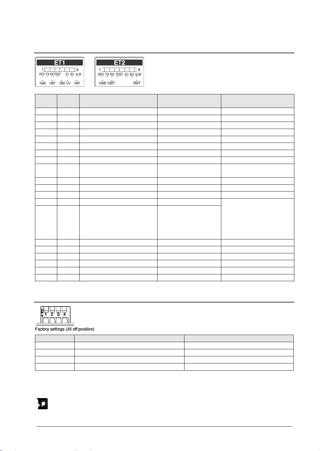
Switch No.
Off
On
1
100BASE-TX/10BASE-T
Note1)
10BASE5
2
Auto connection function is not available
Auto connection function is available
3
Normal mode
Test mode
Note2)
Note2)
2.1.2 Operating Statu s LEDs
ET1
2 2 Connection 2 connected Connection 2 fault Connection 2 not connected
3 3 Connection 3 connected Connection 3 fault Connection 3 not connected
5 5 Connection 5 connected Connection 5 fault Connection 5 not connected
6 6 Connection 6 connected Connection 6 fault Connection 6 not connected
RDY RDY
TX TX Transmitting - Not transmitting
E1 E1 Initialization processing error Recovery possible error
E2 E2
100B 100B 100BASE-TX operati on - Other mode in operat ion
ET2
On Flashing Off
Initialization complete
System error
Hardware error
- Initialization not complete
Warning error
Mail transmission error
Mail reception error
MEWTOCOL error
Normal operation
12V - 12 V power supply on - 12 V power supply off
2.1.3 Mode Setting Switch
4 Test mode 1
Note1) Switching between 100BASE-TX and 10BASE-T is done automatically by auto negotiation
function. Always turn it off when using AFP27901.
Note2) Invalid when the switch 3 is off.
Key Point:
The settings of the mode setting switches become effective at the point when the power supply is turned
on.
2-3
Test mode 2
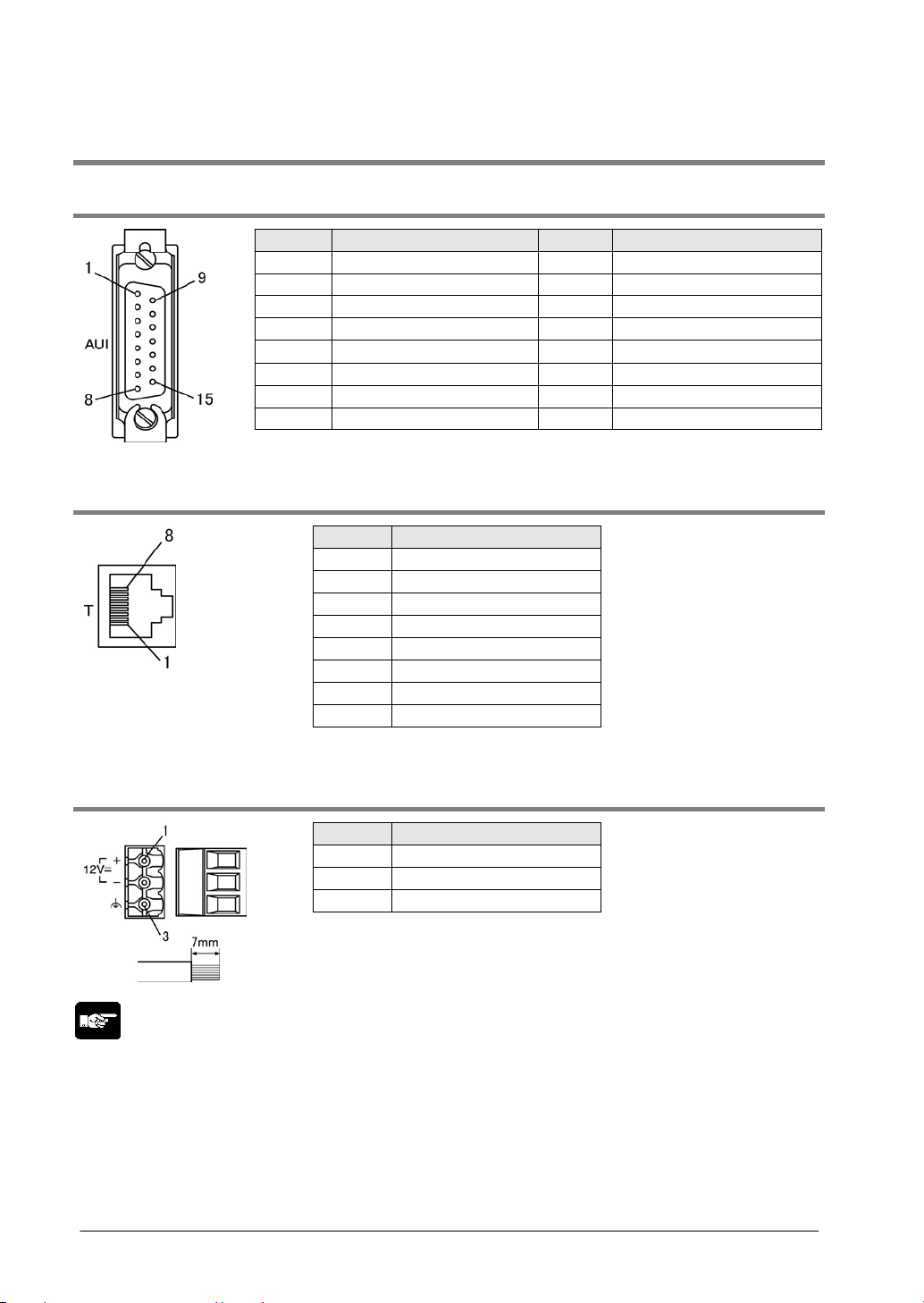
Pin No.
Signal name
Pin No.
Signal name
2
COL+
10
TX-
4
Signal shield
12
RX-
6
GND
14
Power supply shield
8
Signal shield
Shell
F.G.
Pin No.
Signal name
2
TX-
4
Not used
6
RX-
8
Not used
Pin No.
Signal name
2
GND
2.2 Connector Pin La yout
2.2.1 10BASE5(AUI) Connector (with D-SUB 15 pins retain er)
1 Signal shield 9 COL-
3 TX+ 11 Signal shield
5 RX+ 13 12 V DC
7 Not used 15 Not used
2.2.2 100BASE-TX/10BASE-T Connector (RJ45)
1 TX+
3 RX+
5 Not used
7 Not used
2.2.3 External Power Supply Terminal for 10BASE5 (12 V DC)
1 12 V DC
3 F.G.
Note:
- F.G. pin connects to the external metal shell of the 10BASE5 (AUI), 100BASE-TX/10BASE-T
connectors and F.G. pin of the power supply unit.
- Pins should be tightened firmly, to a tightening torque of 0.5 to 0.6 N⋅m).
- The power supply cable should be 0.5 to 2.5 mm
should be 7mm.
2
(AWG20 to 12), and the length of the stripped wire
2-4

Chapter 3
Connection for LAN Cable
3.1 Precautions Concerning Installation
Noise resistance
The Ethernet is a network used in offices and buildings, where there is comparatively little noise. It does
not have a higher resistance to noise than ordinary FA application networks. Consequently, caution is
required when installing the transceiver and hub, and when laying cables.
Guidelines to noise generation
If any of the following are occurring, there is a danger that external noise is affecting the communication
circuit.
- The RX LED on the ET-LAN unit is lighted or flashing, whether or not communication is taking place at
the moment.
Cause: External noise from the communication circuit is penetrating the ET-LAN unit and is being
interpreted as a reception signal.
- An error subsequent to error code 8020H has occurre d.
Cause: External noise from the communication circuit is penetrating the ET-LAN unit and is causing a
communication error.
- An error subsequent to error code A001H has occurred.
Cause: External noise from the communication circuit is penetrating the ET-LAN unit and is causing a
communication error.
Confirm the following items and take any necessary corrective action.
- Check to see if the RXLED lights or flashes, or if a communication error is occurring, in synch with the
operation of the device.
- If either of these is happening in synch with the operation of the device, take whatever measures are
necessary to suppress the generation of noise from the device side.
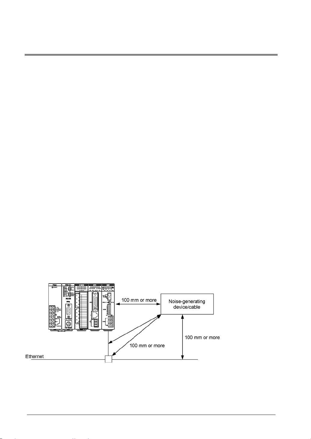
Measures that can be taken in the installation environment
The ET-LAN unit, transceiver, hub, and communication cables should be installed as fast as possible
from high-voltage wires, high-voltage equipment, power lines, power equipment, equipment that
generates strong breaker surges, and the wiring for any of this equipment. At least 100 mm of clearance
should be allowed when installing the equipment.
3-2
 Loading...