

Page 1

PROGRAMMABLE CONTROLLER
FPS/FP2 Fieldbus
Slave Units
Technical Manual
Page 2

BEFORE BEGINNING
Liability and Copyright for the Hardware
This manual and everything described in it are copyrighted. You may not copy this manual, in
whole or part, without written consent of Panasonic Electric Works Europe AG (PEWEU).
PEWEU pursues a policy of continuous improvement of the design and performance of its
products. Therefore we reserve the right to change the manual/product without notice. In no
event will PEWEU be liable for direct, special, incidental, or consequential damage resulting
from any defect in the product or its documentation, even if advised of the possibility of such
damages.
We invite your comments on this manual. Please e-mail us at:
techdoc.peweu@eu.panasonic.com.
Please direct support matters and technical questions to your local Panasonic representative.
LIMITED WARRANTY
If physical defects caused by distribution are found, PEWEU will replace/repair the product
free of charge. Exceptions include:
When physical defects are due to different usage/treatment of the product other than
described in the manual.
When physical defects are due to defective equipment other than the distributed
product.
When physical defects are due to modifications/repairs by someone other than
PEWEU.
When physical defects are due to natural disasters.
Page 3
Important symbols
One or more of the following symbols may be used in this documentation:
DANGER!
The warning triangle indicates especially important safety
instructions. If they are not adhered to, the results could be
fatal or critical injury.
Indicates that you should proceed with caution. Failure to do so may result in
injury or significant damage to instruments or their contents, e.g. data.
Contains important additional information.
Contains an illustrative example of the previous text section.
Indicates that a step-by-step procedure follows.
Indicates where you can find additional information on the subject at hand.
Page 4

Table of Contents
3
Table of Contents
1. Features and Restrictions .................................................... 7
1.1 Fieldbus Slave Units ................................................................................ 8
1.2 Expansion Restrictions and Current Limitations ....................................... 9
1.2.1 Expansion Restrictions for the FP2-FNS Unit ............................................ 9
1.2.2 Expansion Restrictions for the FPΣ FNS Unit ............................................ 9
1.2.3 Limitations on Current Consumption .......................................................... 9
2. Parts and Functions ............................................................ 11
2.1 Fieldbus Slave Units .............................................................................. 12
2.2 FP2 FNS Unit ......................................................................................... 13
2.3 FPΣ FNS Unit ........................................................................................ 14
2.4 FP-FNS Blocks ...................................................................................... 15
2.4.1 FP-FNS Block PROFIBUS DP ................................................................. 15
2.4.2 FP-FNS Block DeviceNet ......................................................................... 16
2.4.3 FP-FNS Block CANopen .......................................................................... 17
2.4.4 FP-FNS Block PROFINET IO .................................................................. 19
2.4.5 FP-FNS Block BACnetIP .......................................................................... 20
2.4.6 FP-FNS Block BACnet MS/TP ................................................................. 22
3. Specifications ...................................................................... 25
3.1 FNS Unit General Specifications ............................................................ 26
3.2 FP-FNS Block General Specifications .................................................... 27
3.2.1 FP-FNS Block PROFIBUS DP General Specifications ............................ 27
3.2.2 FP-FNS Block DeviceNet General Specifications ................................. 27
3.2.3 FP-FNS Block CANopen General Specifications ..................................... 28
3.2.4 FP-FNS Block PROFINET IO General Specifications ............................. 28
Page 5

Table of Contents
4
3.2.5 FP-FNS Block BACnet/IP General Specifications.................................... 28
3.2.6 FP-FNS Block BACnet MS/TP General Specifications ............................ 29
3.3 FP-FNS Block Communication Specifications ........................................ 30
4. Installation and Wiring ........................................................ 31
4.1 Fastening the FP-FNS Block .................................................................. 32
4.2 Removing the FP-FNS Block .................................................................. 34
4.3 Installation of the FP2/FPΣ Unit .............................................................. 35
4.4 Mounting Methods .................................................................................. 39
4.5 Cable Selection ...................................................................................... 40
4.6 Wiring of the FP-FNS Blocks .................................................................. 41
4.6.1 FP-FNS Block PROFIBUS DP Wiring ...................................................... 41
4.6.2 FP-FNS Block DeviceNet Wiring .............................................................. 41
4.6.3 FP-FNS Block CANopen Wiring ............................................................... 43
4.6.4 FP-FNS Block PROFINET IO Wiring ....................................................... 43
4.6.5 FP-FNS Block BACnetIP Wiring............................................................... 43
4.6.6 FP-FNS Block BACnet MS/TP Wiring ...................................................... 44
4.7 Wiring of the FPΣ-FNS Unit .................................................................... 45
5. Programming Examples for FPWIN Pro ............................. 47
5.1 General information ................................................................................ 48
5.2 FNS_InitConfigDataTable Function ........................................................ 49
5.3 FNS_InitConfigNameTable Function ...................................................... 50
5.4 GetPointer Function ................................................................................ 51
5.5 Programming Example, FP-FNS Block ProfibusDP ................................ 52
5.5.1 FNS_ProfibusDP Function Block ............................................................. 54
5.6 Programming Example, FP-FNS Block DeviceNet .................................. 56
Page 6

Table of Contents
5
5.6.1 FNS_DeviceNet Function Block ............................................................... 58
5.7 Programming Example, FP-FNS Block CANopen .................................. 60
5.7.1 FNS_CANopen Function Block ................................................................ 63
5.8 Programming Example, FP-FNS Block Profinet IO ................................ 65
5.8.1 FNS_ProfinetIO Function Block ............................................................... 68
5.9 Programming Example, FP-FNS Block BACnetIP .................................. 70
5.9.1 FNS_BACnetIP Function Block ................................................................ 74
5.10 Programming Example, FP-FNS Block BACnet MS/TP ......................... 77
5.10.1 FNS_BACnetMSTP Function Block ......................................................... 80
6. Outline Dimensions ............................................................. 83
6.1 Outline Dimensions of FP2-FNS Unit ..................................................... 84
6.2 Outline Dimensions of FPΣ FNS Unit ..................................................... 85
6.3 Dimensions of the FP-FNS Blocks ......................................................... 86
6.4 Dimensions with FNS Blocks and Cables ............................................... 87
7. Index..................................................................................... 89
Page 7

Page 8

Chapter 1
Features and Restrictions
Page 9

Features and Restrictions
8
1.1 Fieldbus Slave Units
FP2 and FPΣ (Sigma) Fieldbus Slave Units are preassembled to include a Flexible Network
Slave (FNS) unit and the corresponding FP-FNS block. Panasonic decided to offer customers
these preassembled products to save them time and to prevent damage to the pins in the FNS
units, which bend if the FP-FNS blocks are inserted improperly.
You can still order the FNS units and FP-FNS blocks separately. Please contact your local
sales office.
You can download convenient function blocks for Control FPWIN Pro to help you program the
FP-FNS blocks free of charge from the Panasonic Electric Works Europe AG Web site:
http://www.panasonic-electric-works.com.
FP2 Fieldbus Slave Units
Name
Specifications
Part no.
FP2 PROFIBUS DP Slave Unit
PROFIBUS DP
FP2-DPV1-S
FP2 DeviceNet Slave Unit
DeviceNet
FP2-DEV-S
FP2 CANopen Slave Unit
CANopen
FP2-CAN-S
FP2 PROFINET IO Device Unit
PROFINET IO
FP2-PRT-S
FPΣ Fieldbus Slave Units
Name
Specifications
Part no.
FPΣ PROFIBUS DP Slave Unit
PROFIBUS DP
FPG-DPV1-S
FPΣ DeviceNet Slave Unit
DeviceNet
FPG-DEV-S
FPΣ CANopen Slave Unit
CANopen
FPG-CAN-S
FPΣ PROFINET IO Device Unit
PROFINET IO
FPG-PRT-S
FPΣ BACnet-IP Slave Unit
BACnet/IP
FPG-BACIP-S
FPΣ BACnet-MSTP Slave Unit
BACnet MS/TP
FPG-BACMSTP-S
Page 10

Expansion Restrictions and Current Limitations
9
1.2 Expansion Restrictions and Current Limitations
1.2.1 Expansion Restrictions for the FP2-FNS Unit
The number of FP2-FNS units is restricted by the size of the FP2 backplane.
1.2.2 Expansion Restrictions for the FPΣ FNS Unit
The FP-FNS units are connected to the left side of the control unit via the FP expansion
connector. Up to 4 expansion units can be connected to the left side of the control unit.
1.2.3 Limitations on Current Consumption
The 5V DC power used to drive the internal circuit of each unit is supplied from the power
supply unit of the FP2 through the internal bus of the backplane or from the FP control unit
through the expansion connector.
Pay attention to the combination of units so that the rated capacity of the power supply is not
exceeded.
Page 11

Page 12

Chapter 2
Parts and Functions
Page 13

Parts and Functions
12
2.1 Fieldbus Slave Units
FP2 and FPΣ Fieldbus Slave Units (see page 8) are preassembled to include:
an FP2 FNS unit (see page 13)
or an FPΣ FNS unit (see page 14)
and the corresponding FP-FNS block (see page 15).
Page 14
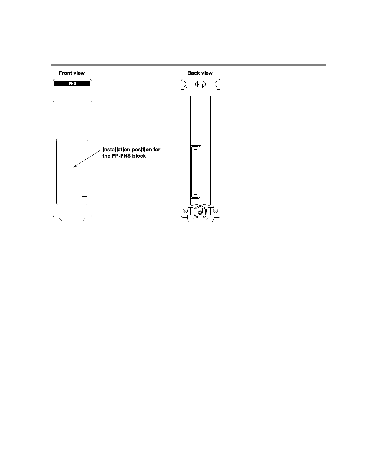
FP2 FNS Unit
13
2.2 FP2 FNS Unit
Page 15
Parts and Functions
14
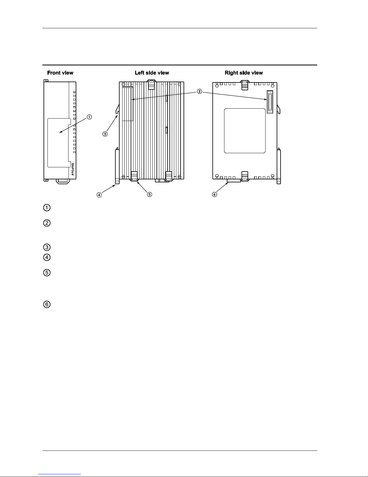
2.3 FPΣ FNS Unit
Installation position for FP-FNS block
FP expansion connector
Used to connect the unit to the control unit or other expansion units.
DIN standard rail attachment
DIN rail attachment lever
Expansion hook
Used to secure an expansion unit. The hook is also used for installation on the flat type
mounting plate (part no. AFP0804).
Function earth connector
At least one of the pins must be connected to function earth to achieve proper EMC behavior.
The FP-FNS unit is connected to the left side of the control unit via the FP expansion
connector.
Page 16
FP-FNS Blocks
15
2.4 FP-FNS Blocks
Various FP-FNS blocks are available to meet your networking needs.
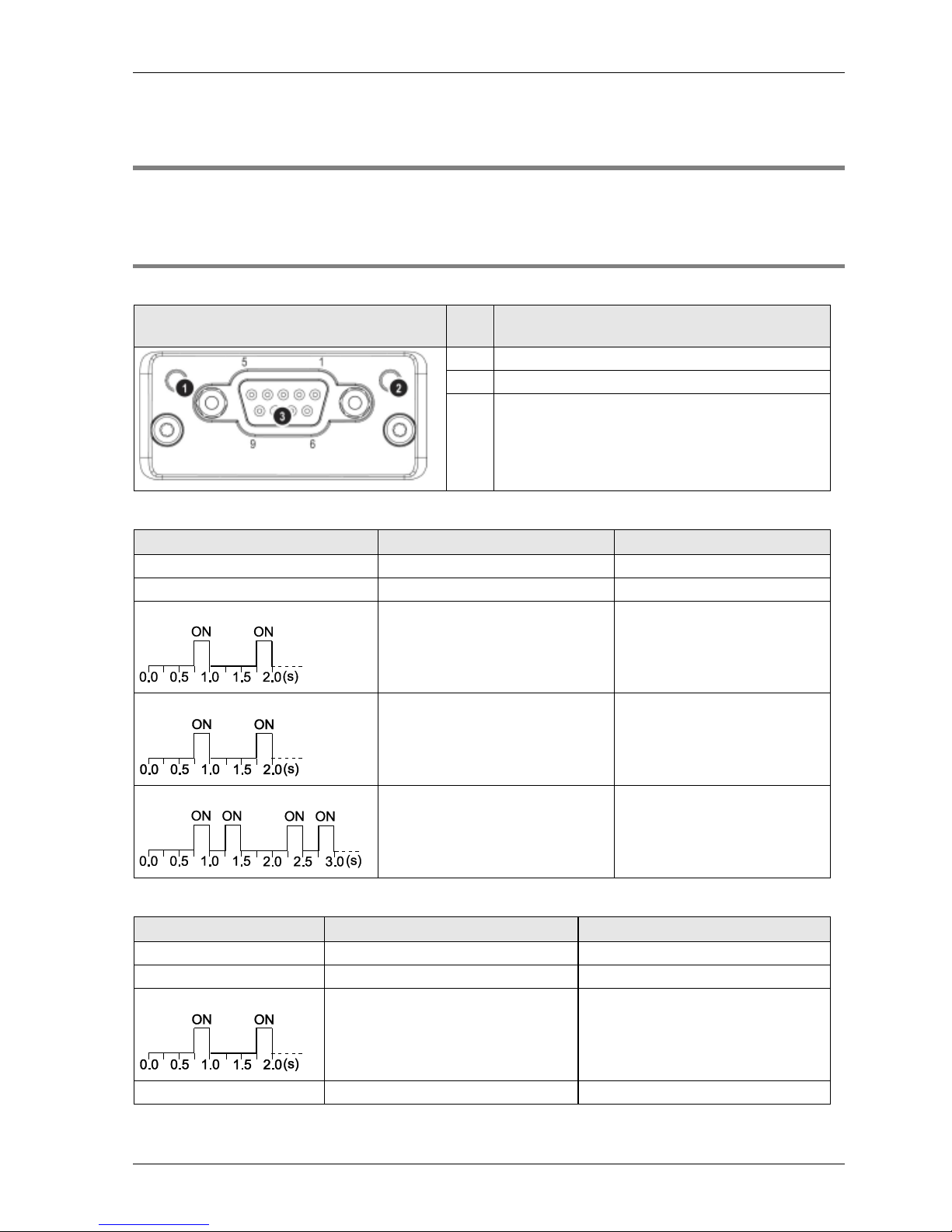
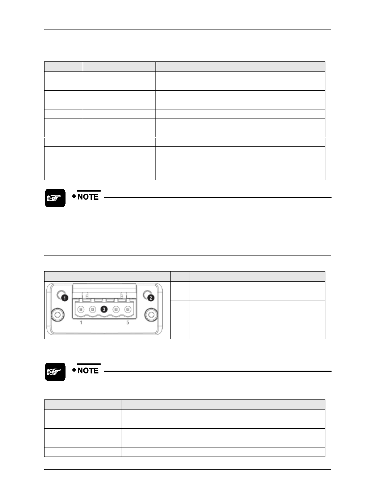
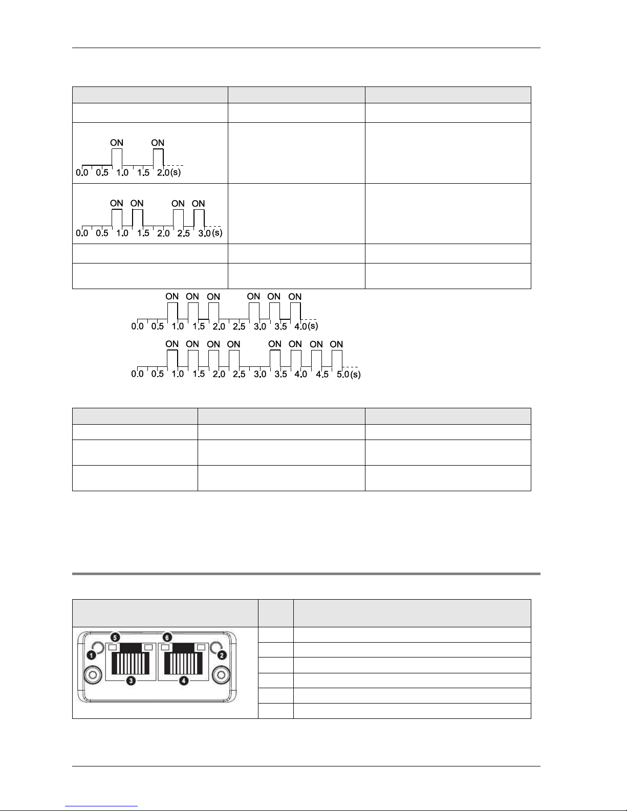
2.4.1 FP-FNS Block PROFIBUS DP
This FP-FNS block connects the unit to a PROFIBUS network.
Front view
No.
Item
1
Operation mode
2
Status
3
PROFIBUS connector (DB9F)
Operation Mode
State
Indication
Comments
Off
Not online/No power
-
Green
Online, data exchange
-
Flashing green
Online, clear
-
Flashing red (1 flash)
Parametrization error
-
Flashing red (2 flashes)
PROFIBUS configuration error
Slave configuration does not
match master configuration
Status
State
Indication
Comments
Off
No power or not initialized
FP-FNS state = 'SETUP¨' or 'NW_INIT'
Green
Initialized
FP-FNS has left the 'NW_INIT' state
Flashing green
Initialized, diagnostic event(s) present
Extended diagnostic bit is set
Red
Exception error
FP-FNS state = 'EXCEPTION'
Page 17
Parts and Functions
16
PROFIBUS connector, DB9F, 9-pin Sub-D female
Pin
Signal
Description
1
-
- 2 -
- 3 B Line
Positive RxD/TxD, RS485 level
4
RTS
Request to send
5
GND
Bus ground (isolated)
6
+5V bus output (see note)
+5V termination power (isolated)
7
-
- 8 A Line
Negative RxD/TxD, RS485 level
9
-
-
Housing
Cable shield
FP: Internally connected to the function earth connector of the
FNS unit.
FP2: Internally connected to the earth terminal of the power unit.
Any current drawn from pin 6, the +5V bus output pin, will affect the total power
consumption.
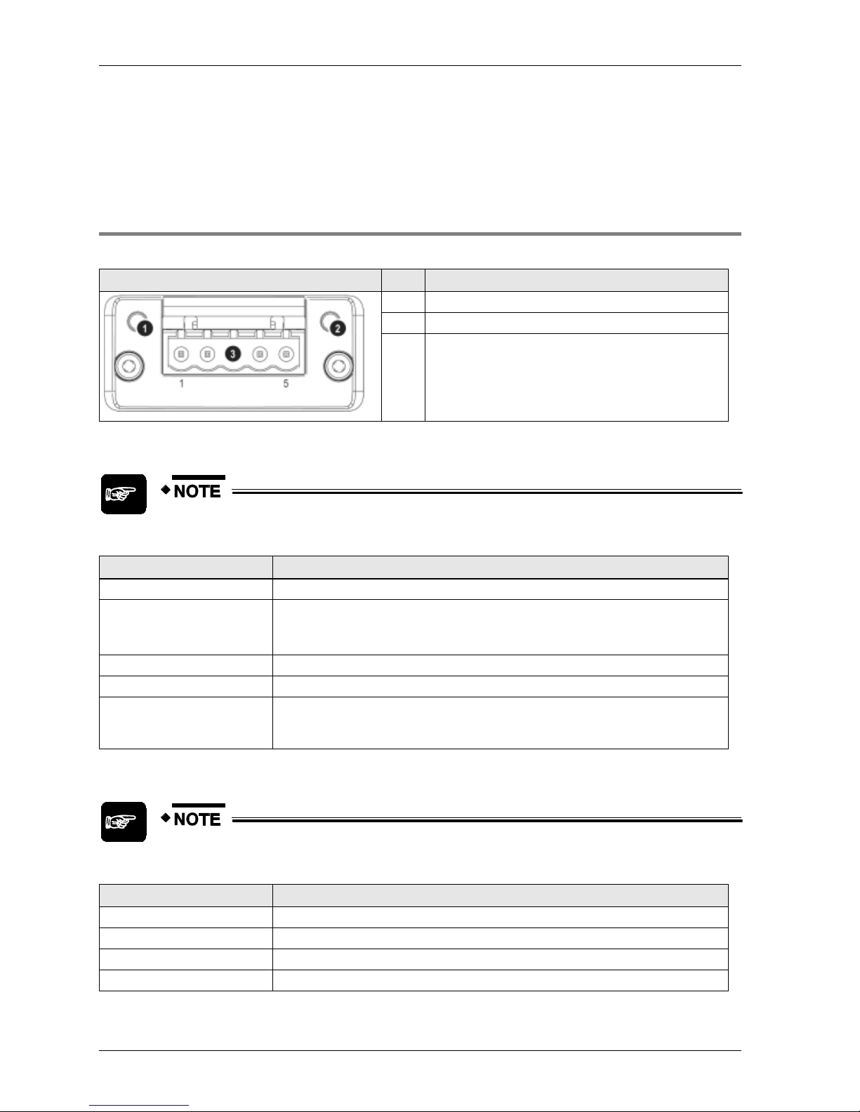
2.4.2 FP-FNS Block DeviceNet
This FP-FNS block connects the unit to a DeviceNet network.
Front view
No.
Item
1
Network status LED
2
Module status LED
3
DeviceNet connector
Network Status
During start-up, an LED test is performed according to the DeviceNet standard.
State
Indication
Off
Not online/No power
Green
Online, one or more connections are established
Flashing green (1Hz)
Online, no connections established
Red
Critical link failure
Flashing red (1Hz)
One or more connections timed out
Page 18
FP-FNS Blocks
17
Module Status
During start-up, an LED test is performed according to the DeviceNet standard.
State
Indication
Off
No power or not initialized
Green
Operating in normal condition
Flashing green (1Hz)
Missing or incomplete configuration, device needs to be configured
Red
Unrecoverable fault(s)
Flashing red (1Hz)
Recoverable fault(s)
DeviceNet Connector
Pin
Signal
Description
1
V-
Negative bus supply voltage (see note)
2
CAN_L
CAN low bus line
3
SHIELD
Cable shield
4
CAN_H
CAN high bus line
5
V+
Positive bus supply voltage (see note)
Mandatory 24V bus power.
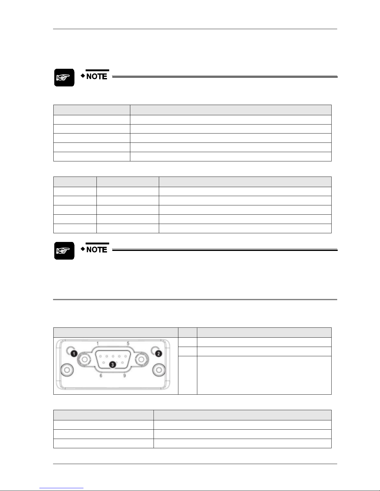
2.4.3 FP-FNS Block CANopen
This FP-FNS block connects the unit to a CANopen network.
AFPN-AB6218
Front view
No.
Item
1
RUN LED
2
ERROR LED
3
CANopen interface
RUN
State
Indication
Off
No power or device is in "Exception" state
Flickering green (10Hz)
Automatic baud rate detection
Single flash green
Device stopped
Page 19
Parts and Functions
18
State
Indication
Blinking green (2.5Hz)
Device is in "pre-operational" state
Green
"Operational" state
Red
Fatal event encountered. Bus interface is in physically passive state.
ERROR
State
Indication
Off
No power or device is in working condition
Single flash red
A bus error counter has reached warning limit
Flickering red (10Hz)
LSS (Layer Setting Service) in progress
Double flash red
Error control event has occurred
Red
Bus off or fatal event
CANopen Interface for AFPN-AB6218
Pin
Signal
Description
1
2
CAN_L
CAN low bus line (dominant low)
3
CAN_GND
Negative bus power supply input
4
5
6
7
CAN_H
CAN high bus line (dominant high)
8
9
Page 20
FP-FNS Blocks
19
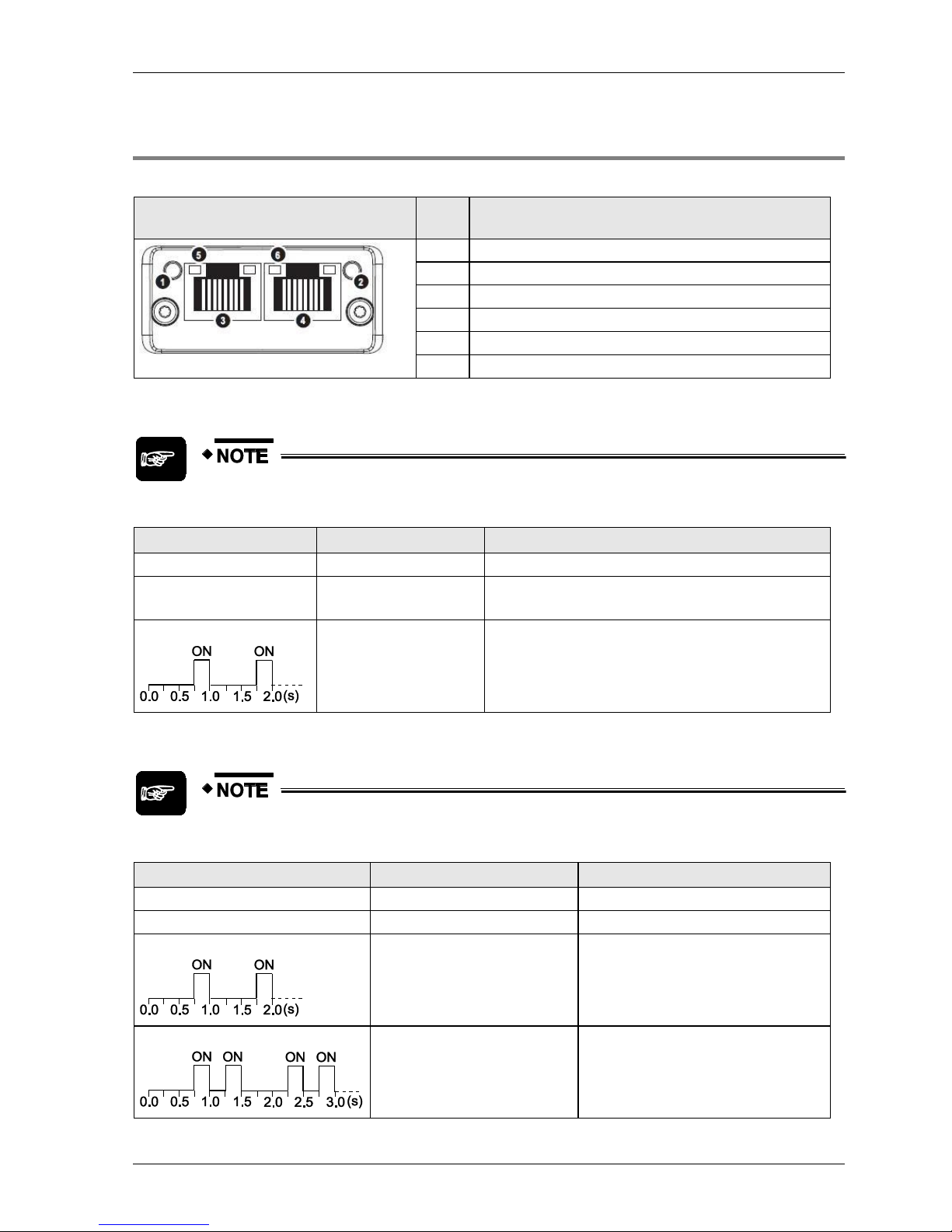
2.4.4 FP-FNS Block PROFINET IO
This FP-FNS block connects the unit to a PROFINET IO network.
Front view
No.
Item
1
Network status LED
2
Module status LED
3
Ethernet port 1
4
Ethernet port 2
5
Link/Activity LED (port 1)
6
Link/Activity LED (port 2)
Network Status
During start-up, a test sequence is performed on this LED.
State
Indication
Comments
Off
Offline
No power, or no connection with the IO controller
Green
Online (RUN)
Connection with IO controller established
IO controller in RUN state
Green, flashing
Online (STOP)
Connection with IO controller established
IO controller in STOP state
Module Status
During start-up, a test sequence is performed on this LED.
State
Indication
Comments
Off
No power or not initialized
FP-FNS state = 'SETUP¨' or 'NW_INIT'
Green
Normal operation
FP-FNS has left the 'NW_INIT' state
Green, 1 flash
Diagnostic event(s)
Diagnostic event(s) present
Green, 2 flashes
Blink
Used by engineering tools to identify the
node on the network.
Page 21
Parts and Functions
20
State
Indication
Comments
Red
Exception error
FP-FNS state = 'EXCEPTION'
Red, 1 flash
Configuration Error
Expected configuration by controller
differs from real configuration.
Red, 2 flashes
IP Address Error
IP address not set
Red, 3 flashes*
Station Name Error
Station Name not set
Red, 4 flashes*
Internal Error
FP-FNS has encountered a major
internal error.
*3 flashes:
*4 flashes:
LINK/Activity LED
LED State
Indication
Comments
Off
No Link
No link, no communication present
Green
Link
Ethernet link established, no
communication present
Green, flickering (10Hz)
Activity
Ethernet link established,
communication present
Ethernet interface, RJ45
The Ethernet interface operates at 100Mbit, full duplex, as required by PROFINET.
2.4.5 FP-FNS Block BACnetIP
This FP-FNS block connects the unit to a BACnetIP network.
Front view
No.
Item
1
Network status LED
2
Module status LED
3
Ethernet port 1
4
Ethernet port 2
5
Link/Activity LED (port 1)
6
Link/Activity LED (port 2)
Page 22

FP-FNS Blocks
21
Network Status
During start-up, a test sequence is performed on this LED.
State
Indication
Comments
Off
Offline
No power, or no IP address
Green
Online (RUN)
On-line, one or more BACnet messages have arrived
Module has active COV subscriptions
At least one value object has one or more events
enabled
Green,flashing
Online, waiting
Waiting for first BACnet message
Red
Duplicate IP address
FATAL error
Red, flashing
Connection timeout
No BACnet message has been received within the
configured 'process active timeout’ time.
A COV or Alarm/Event notification could not be sent
to its recipient.
Module Status
During start-up, a test sequence is performed on this LED.
State
Indication
Comments
Off
No power
FP-FNS state = 'SETUP¨' or 'NW_INIT'
Green
Normal operation
FP-FNS has left the 'NW_INIT' state
Red/green, alternating
Firmware update from file
system in progress
Red
Major fault
EXCEPTION-state, FATAL error etc.
Red, flashing
Recoverable fault(s)
LINK/Activity LED
LED State
Indication
Comments
Off
No Link
No link, no communication present
Green
Link (100 Mbit/s) established
Ethernet link established, no
communication present
Green, flickering (10Hz)
Activity (100 Mbit/s)
Ethernet link established,
communication present
Yellow
Link (10 Mbit/s) established
Ethernet link established, no
communication present
Yellow, flickering (10Hz)
Activity (10 Mbit/s)
Ethernet link established,
communication present
Page 23
Parts and Functions
22
Ethernet interface, RJ45
The Ethernet interface supports autonegotiation and Auto MDI-X, with 10/100Mbit, full or half
duplex operation.
2.4.6 FP-FNS Block BACnet MS/TP
This FP-FNS block connects the unit to a BACnetMS/TP network.
Front view
No.
Item
1
Network status LED
2
Module status LED
3
BACnet MS/TP connector
Network Status
During start-up, a test sequence is performed on this LED.
State
Indication
Off
No power
Green
On-line, one or more BACnet messages have arrived
Module has active COV subscriptions
At least one value object has one or more events enabled
Flashing green (1Hz)
On-line, waiting for first BACnet message
Red
FATAL error
Flashing red (1Hz)
Connection timeout. No BACnet message has been received within the configured
‘process active timeout’ time.
A COV or Alarm/Event notification could not be sent to its recipient
Module Status
During start-up, a test sequence is performed on this LED.
State
Indication
Off
No power
Green
Operating in normal condition
Red
Major fault (EXCEPTION-state, FATAL error etc.)
Flashing red (1Hz)
Recoverable fault(s)
Page 24

FP-FNS Blocks
23
BACnet MS/TP Connector
Pin
Signal
Description
1
Common
Signal common
2
Data-
Negative RS485 RxD/TxD
3
Shield
Cable shield
4
Data+
Positive RS485 RxD/TxD
5
(Not used)
(Not used)
Page 25

Page 26

Chapter 3
Specifications
Page 27

Specifications
26
3.1 FNS Unit General Specifications
Item
Description
Operating temperature
0 to +55°C/32 to +131°F
Storage temperature
-20 to +70°C/-4 to +158°F
Operating humidity
30 to 85% RH (non-condensing)
Storage humidity
30 to 85% RH (non-condensing)
Vibration resistance
10 to 55Hz, 1 cycle/min: double amplitude of 0.75mm/0.030in., 10 min. on 3 axes
Shock resistance
Shock of 98m/s2 or more, 4 times on 3 axes
Operation condition
Free from corrosive gases and excessive dust
Current consumption
55mA or less at 5V
Weight (main unit)
FP2-FNS: 88g
FP-FNS: 61g
Page 28

FP-FNS Block General Specifications
27
3.2 FP-FNS Block General Specifications
3.2.1 FP-FNS Block PROFIBUS DP General Specifications
Item
Description
Operating temperature
0 to +55°C/32 to +131°F
Storage temperature
-20 to +70°C/-4 to +158°F
Operating humidity
30 to 85% RH (non-condensing)
Storage humidity
30 to 85% RH (non-condensing)
Vibration resistance
10 to 55Hz, 1 cycle/min: double amplitude of 0.75mm/0.030in., 10 min. on 3 axes
Shock resistance
Shock of 98m/s2 or more, 4 times on 3 axes
Immunity
EN61000-4-2, EN61000-4-3, EN61000-4-4, EN61000-4-5, EN61000-4-6
Operation condition
Free from corrosive gases and excessive dust
Insulation resistance
Min. 100M (measured with a 500V DC megger)
Breakdown voltage
500V AC, 1 min. between DC external terminal and ground terminal
Current consumption
230mA or less at 5V
Weight
31g
3.2.2 FP-FNS Block DeviceNet General Specifications
Item
Description
Operating temperature
0 to +55°C/32 to +131°F
Storage temperature
-20 to +70°C/-4 to +158°F
Operating humidity
30 to 85% RH (non-condensing)
Storage humidity
30 to 85% RH (non-condensing)
Vibration resistance
10 to 55 Hz, 1 cycle/min: double amplitude of 0.75mm/0.030in., 10 min. on 3 axes
Shock resistance
Shock of 98m/s2 or more, 4 times on 3 axes
Immunity
EN61000-4-2, EN61000-4-3, EN61000-4-4, EN61000-4-5, EN61000-4-6
Operation condition
Free from corrosive gases and excessive dust
Insulation resistance
Min. 100M (measured with a 500 V DC megger)
Breakdown voltage
500V AC, 1 min. between DC external terminal and ground terminal
Current consumption
65mA or less at 5V; additional 140mA for bus power at 24V
Weight
32g
Page 29

Specifications
28
3.2.3 FP-FNS Block CANopen General Specifications
Item
Description
Operating temperature
0 to +55°C/32 to +131°F
Storage temperature
-20 to +70°C/-4 to +158°F
Operating humidity
30 to 85% RH (non-condensing)
Storage humidity
30 to 85% RH (non-condensing)
Vibration resistance
10 to 55Hz, 1 cycle/min: double amplitude of 0.75mm/0.030in., 10 min. on 3 axes
Shock resistance
Shock of 98m/s2 or more, 4 times on 3 axes
Immunity
EN61000-4-2, EN61000-4-3, EN61000-4-4, EN61000-4-5, EN61000-4-6
Operation condition
Free from corrosive gases and excessive dust
Insulation resistance
Min. 100M (measured with a 500V DC megger)
Breakdown voltage
500V AC, 1 min. between DC external terminal and ground terminal
Current consumption
65mA or less at 5V; additional 140mA for bus power at 24V
Weight
32g
3.2.4 FP-FNS Block PROFINET IO General Specifications
Item
Description
Operating temperature
0 to +55°C/32 to +131°F
Storage temperature
-20 to +70°C/-4 to +158°F
Operating humidity
30 to 85% RH (non-condensing)
Storage humidity
30 to 85% RH (non-condensing)
Vibration resistance
10 to 55Hz, 1 cycle/min: double amplitude of 0.75mm/0.030in., 10 min. on 3 axes
Shock resistance
Shock of 98m/s2 or more, 4 times on 3 axes
Immunity
EN61000-4-2, EN61000-4-3, EN61000-4-4, EN61000-4-5, EN61000-4-6
Operation condition
Free from corrosive gases and excessive dust
Insulation resistance
Min. 100M (measured with a 500V DC megger)
Breakdown voltage
500V AC, 1 min. between DC external terminal and ground terminal
Current consumption
375mA or less at 5V
Weight
31g
3.2.5 FP-FNS Block BACnet/IP General Specifications
Item
Description
Operating temperature
0 to +55°C/32 to +131°F
Storage temperature
-20 to +70°C/-4 to +158°F
Operating humidity
30 to 85% RH (non-condensing)
Storage humidity
30 to 85% RH (non-condensing)
Vibration resistance
10 to 55Hz, 1 cycle/min: double amplitude of 0.75mm/0.030in., 10 min. on 3 axes
Page 30

FP-FNS Block General Specifications
29
Item
Description
Shock resistance
Shock of 98m/s2 or more, 4 times on 3 axes
Immunity
EN61000-4-2, EN61000-4-3, EN61000-4-4, EN61000-4-5, EN61000-4-6
Operation condition
Free from corrosive gases and excessive dust
Insulation resistance
Min. 100M (measured with a 500V DC megger)
Breakdown voltage
500V AC, 1 min. between DC external terminal and ground terminal
Current consumption
380mA or less at 5V
Weight
31g
3.2.6 FP-FNS Block BACnet MS/TP General Specifications
Item
Description
Operating temperature
0 to +55°C/32 to +131°F
Storage temperature
-20 to +70°C/-4 to +158°F
Operating humidity
30 to 85% RH (non-condensing)
Storage humidity
30 to 85% RH (non-condensing)
Vibration resistance
10 to 55Hz, 1 cycle/min: double amplitude of 0.75mm/0.030in., 10 min. on 3 axes
Shock resistance
Shock of 98m/s2 or more, 4 times on 3 axes
Immunity
EN61000-4-2, EN61000-4-3, EN61000-4-4, EN61000-4-5, EN61000-4-6
Operation condition
Free from corrosive gases and excessive dust
Insulation resistance
Min. 100M (measured with a 500V DC megger)
Breakdown voltage
500V AC, 1 min. between DC external terminal and ground terminal
Current consumption
200mA or less at 5V
Weight
31g
Page 31

Specifications
30
3.3 FP-FNS Block Communication Specifications
PROFIBUS, DeviceNet, CANopen
Item
PROFIBUS
DeviceNet
CANopen
Baud rate
Automatic baud rate
detection
9.6kbaud to 12Mbaud
Automatic baud rate
detection
125kbps to 500kbps
Automatic baud rate
detection
10kbps to 1Mbps
Isolation
Galvanically isolated bus
electronics
Galvanically isolated bus
electronics
Galvanically isolated bus
electronics
Connection types
DP-V0: process data is
accessed from the
PROFIBUS network as
cyclical I/O data
Cyclic connections
COS (Change of State)
Bit strobe connections
Polled connections
Explicit connections
PDO (Process Data Object)
Exchange via:
Cyclic Synchronous
Acyclic Synchronous
COS
Timer-driven
connections
Maximum inputs/outputs
76 words altogether for
inputs and outputs (in units
of 1, 2 or 4 words)
E.g. for cyclic connections:
128 words in each direction
128 words (for TPDOs and
RPDOs)
Additional features
Diagnostic support
UCMM capable
CIP Parameter Object
Diagnostic support
Diagnostic support
Interface
DB9F (9-pin Sub-D female)
5-pin terminal block
9-pin Sub-D male
(AFPN-AB6218)
PROFINET IO, BACnet/IP, BACnet MS/TP
Item
PROFINET IO
BACnet/IP
BACnet MS/TP
Baud rate
100Mbit/s
Full duplex
100Mbit/s
10Mbit/s
Full duplex
Half duplex
9600kbits/s
19200kbits/s
38400kbits/s
76800kbits/s
Isolation
Galvanically isolated bus
electronics
Galvanically isolated bus
electronics
Galvanically isolated bus
electronics
Connection types
PROFINET IO
conformance class B
Cyclic data exchange
via PROFINET IO
Real Time (RT)
communication, 2ms
cycle time
Change Of Value (COV)
notification
Alarm/ Event
functionality
Change Of Value (COV)
notification
Alarm/ Event
functionality
Maximum inputs/
outputs
128 words of Real Time I/O
data in each direction
256-byte write process data
256-byte write process data
Additional features
Diagnostic support
Diagnostic support
Diagnostic support
Interface
Integrated 2-port switch: 2 x
RJ45 socket
Integrated 2-port switch: 2 x
RJ45 socket
5-pin terminal block
Page 32

Chapter 4
Installation and Wiring
Page 33

Installation and Wiring
32
4.1 Fastening the FP-FNS Block
Pins may bend!
To ensure that the pins in the FP-FNS do not bend or break, which will ruin the
FP-FNS unit, read the following installation instructions carefully and follow them
precisely.
Make sure you are not electrostatically charged before you touch the FP-FNS
block: the discharge of static electricity can damage parts and equipment.
1. CAREFULLY insert the FP-FNS block into the FNS unit's installation port. Do not
force the block into the unit! Do not bend the pins!
Make sure that the FP-FNS block is properly placed in the installation port of the
FNS unit and properly guided in the slot so that there is no space between the
FP-FNS block and the PCB.
2. Push the FP-FNS block into the main unit until it stops. Do not force it!
If the block stops with 5mm of space remaining until it is flush with the surface of
the FP-FNS unit, the pins are not alligned properly! Pull the block out and reinsert
it carefully, making sure it is properly guided.
Page 34

Fastening the FP-FNS Block
33
3. While flush with the unit's surface, tighten the mounting screws.
Make sure the mounting mechanics fit into the fastening support holes of the PCB.
When tightening the FP-FNS block, use a TORX driver with a blade size of T9.
The recommended tightening torque is 0.25Nm.
TORX® are registered trademarks of Acument™ Global Technologies.
Page 35

Installation and Wiring
34
4.2 Removing the FP-FNS Block
1. Loosen the mounting screws.
2. Pull the FP-FNS block out of the installation port of the FNS unit.
Page 36

Installation of the FP2/FPΣ Unit
35
4.3 Installation of the FP2/FPΣ Unit
Warning!
Read the following notes carefully before installing the
unit!
Failure to follow these instructions could lead to fire or
damage the equipment.
Installation environment
Be sure to install the unit in locations designed for electrical equipment, e.g. in a closed
metal cabinet such as a switch cabinet.
Avoid installing the unit in the following locations:
Ambient temperatures outside the range of 0°C to 55°C.
Ambient humidity outside the range of 30% to 85% RH (at 25°C, non-condensing)
Sudden temperature changes causing condensation
Inflammable or corrosive gases
Excessive airborne dust, metal particles or salts
Benzine, paint thinner, alcohol or other organic solvents or strong alkaline solutions
such as ammonia or caustic soda
Excessive vibration or shock
Direct sunlight
Water or oil in any form including spray or mist
Static electricity
Before touching the unit or equipment, always touch some grounded metal to
discharge any static electricity you may have generated (especially in dry locations).
The discharge of static electricity can damage parts and equipment.
Avoid noise interference from the following sources:
Influence from power transmission lines, high voltage equipment, power cables, power
equipment, radio transmitters, or any other equipment that would generate high
switching surges.
If noise occurs in the power supply line even after the above countermeasures are
taken, it is recommended to supply power through an insulation transformer, noise
filter, or the like.
Cleaning
Do not use thinner based cleaners because they deform the unit case and fade the
colors.
Page 37

Installation and Wiring
36
Measures regarding heat discharge
Always install the CPU orientated with the TOOL port facing outward on the bottom in
order to prevent the generation of heat.
Do NOT install the CPU as shown below.
Do not install the unit above devices which generate heat such as heaters,
transformers or large scale resistors.
Page 38

Installation of the FP2/FPΣ Unit
37
Installation space
Leave at least 50mm of space between the wiring ducts of the unit and other devices to
allow heat radiation and unit replacement.
Maintain a minimum of 100mm between devices to avoid adverse effects from noise
and heat when installing a device or panel door to the front of the unit.
Page 39

Installation and Wiring
38
For the FP2/FP2SH, keep the first 170mm from the PLC front surface clear of objects
to allow the connecting of programming tools. For the FP, the distance should be at
least 130mm.
Page 40

Mounting Methods
39
4.4 Mounting Methods
FP-FNS Unit
You can attach up to 4 expansion units, including the FP-FNS unit, to the left side of the FP
CPU. You can mount all units on a DIN rail.
For more information, please refer to the FP User's Manual.
FP2-FNS Unit
Install the FP2-FNS unit on the FP2 backplane. You can mount the backplane on a DIN rail.
For more information, please refer to the FP2 Hardware Manual.
Page 41

Installation and Wiring
40
4.5 Cable Selection
Select a cable suitable for the network used.
PROFIBUS
Use a standard PROFIBUS cable and a standard 9-pin Sub-D PROFIBUS connector.
CANopen
Use a standard CANopen cable and a standard 9-pin Sub-D CANopen connector.
DeviceNet
Use a standard DeviceNet cable.
The round cable contains five wires: one twisted pair (red and black) for 24V DC power, one
twisted pair (blue and white) for signal, and a drain wire (bare).
You can find proposals for standard cables on the Open DeviceNet Vendor Association's Web
site (ODVA): http://www.odva.org. (http://www.odva.org/default.aspx?tabid=84)
PROFINET
Use a standard PROFINET Ethernet cable and a standard RJ45 connector.
BACnet/IP
Use a standard Ethernet cable and a standard RJ45 connector.
BACnet MS/TP
Use a standard RS485 cable.
Page 42

Wiring of the FP-FNS Blocks
41
4.6 Wiring of the FP-FNS Blocks
4.6.1 FP-FNS Block PROFIBUS DP Wiring
Use a standard PROFIBUS cable and standard 9-pin Sub-D male PROFIBUS connectors.
We recommend using a straight (0°) bus interface connector (e.g. PR 103-658). When a
horizontal (90°) bus interface connector is used, the cables will be directed toward the top of
the unit, which may cause difficulties when installing other devices in a control cabinet.
4.6.2 FP-FNS Block DeviceNet Wiring
Open style connector/suitable wire
DeviceNet has a standard open style connector.
If additional connectors are needed, use the standard CAN 5-pin open style connectors
manufactured by Phoenix Contact.
No. of contacts
Phoenix Contact product ID
5
Model no.
Product no.
MSTB 2,5/ 5-ST-5,08 ABGY AU
1849037
Terminal block for DeviceNet
For a suitable wire, please refer to cable selection (see page 40).
Wiring method
Attach a plug-in, open style connector to a cable.
1. Strip 65mm (2.6in.) to 75mm (3in.) of the outer jacket from the end of the cable,
leaving no more than 6.4mm (0.25in.) of the braided shield exposed.
Page 43

Installation and Wiring
42
2. Wrap the end of the cable with 38mm (1.5in.) of shrink wrap, covering part of the
exposed conductors and part of the trunk line insulation.
3. Strip 8.1mm (0.32in.) of the insulation from the end of each of the insulated
conductors.
4. Insert each conductor into the appropriate clamping cavity of the open style
connector or the screw terminal on the device, according to the color of the cable
insulation:
Wire color
Wire identity
Usage
White
CAN_H
Signal
Blue
CAN_L
Signal
Bare
Drain
Shield
Black
V-
Power
Red
V+
Power
5. Tighten the clamping screws to secure each conductor. The male contacts of the
device connector must match the female contacts of the connector.
When removing the wire's insulation, be careful not to scratch the core wire.
Do not twist the wires to connect them.
Do not solder the wires to connect them. The solder may break due to
vibration.
Page 44

Wiring of the FP-FNS Blocks
43
After wiring, make sure stress is not applied to the wire.
In the terminal block socket, make sure to clamp the wire in place by turning
the tightening screw clockwise.
4.6.3 FP-FNS Block CANopen Wiring
Use a standard CANopen cable and standard 9-pin Sub-D female CANopen connectors.
We recommend using a straight (0°) bus interface connector. When a horizontal (90°) bus
interface connector is used, the cables will be directed toward the top of the unit, which may
cause difficulties when installing other devices in a control cabinet.
4.6.4 FP-FNS Block PROFINET IO Wiring
PROFINET uses a transmission rate of 100Mbit/s in full-duplex mode for data communication.
Therefore, the cables used must fulfill these requirements. Use a standard, shielded,
twisted-pair Ethernet cable (100 BASE TX) with a minimum category 5 rating and at least four
wires. For example, STP5 is a shielded, twisted pair cable of category 5.
Please use standard RJ45 connectors. RJ45 connectors are available with different IP degrees
of protection.
The maximum distance between two devices should not exceed 100m.
4.6.5 FP-FNS Block BACnetIP Wiring
BACnetIP uses a transmission rate of 10/100Mbit/s in full or duplex mode for data
communication. Therefore, the cables used must fulfill these requirements. Use a standard,
shielded, twisted-pair Ethernet cable (100 BASE TX) with a minimum category 5 rating and at
least four wires. For example, STP5 is a shielded, twisted pair cable of category 5.
Please use standard RJ45 connectors. RJ45 connectors are available with different IP degrees
of protection.
The maximum distance between two devices should not exceed 100m.
Page 45

Installation and Wiring
44
4.6.6 FP-FNS Block BACnet MS/TP Wiring
Open style connector/suitable wire
BACnet MS/TP has a standard open style connector.
If additional connectors are needed, use the standard 5-pin, open style connectors
manufactured by Phoenix Contact.
No. of contacts
Phoenix Contact product ID
5
Model no.
Product no.
MSTB 2,5/ 5-ST-5,08 BK AU
1767915
Terminal block for BACnet MS/TP
For a suitable wire, please refer to cable selection (see page 40).
Page 46

Wiring of the FPΣ-FNS Unit
45
4.7 Wiring of the FPΣ-FNS Unit
The FP-FNS unit has a spring-cage connection type (2-pin) or screw (3-pin) terminal block on
its lower side to connect to function earth. As the pins are internally bridged, one of the pins
should be connected to function earth for proper EMC behaviour. Use the following items for
wiring.
Accessory terminal block
If additional connectors are needed, use the connector manufactured by Phoenix Contact.
No. of contacts
Phoenix Contact Model no.
Phoenix Contact Product no.
2
FK-MC 0.5/2-ST-2.5
18 81 32 5
3
MC 1,5/ 3-ST-3,5
18 40 37 9
Suitable wire for spring-cage connection type terminal (2-pin)
No. of wires
Size
Cross-sectional area
1
AWG 26-20
0.14-0.5mm²
Suitable wire for screw terminal (3-pin)
No. of wires
Size
Cross-sectional area
1
AWG 28-16
0.14-1.5mm²
Either fixed or flexible wires can be used to connect the function earth.
Wiring method for the spring-cage connection type
Fixed wires with a diameter>0.2mm² and flexible wires with a wire end ferrule can be plugged
in the clamp. When using smaller diameters or flexible wires without a ferrule, you must push
the orange opening lever to plug in the wire.
When removing the wire’s insulation, be careful not to scratch the core wire.
Do not twist the wires to connect them.
Do not solder the wires to connect them. The solder may break from
vibrations.
Page 47

Installation and Wiring
46
After wiring, make sure stress is not applied to the wire.
1. Remove a portion of the wire’s insulation.
2. Press the orange opening lever of the connector using a tool such as a flat-blade
screwdriver.
3. Insert the wire into the connector until it stops while pressing the opening lever.
4. Release the opening lever.
Page 48

Chapter 5
Programming Examples for FPWIN Pro
Page 49

Programming Examples for FPWIN Pro
48
5.1 General information
In these programming examples for Control FPWIN Pro, several different functions and
function blocks are used, which are explained in the following sections.
Make sure you use at least version 5.2.3 of FPWIN Pro, into which the functions necessary for
programming the FP-FNS blocks are integrated.
These example programs are used to configure the various FNS units and to start
communication with the specific network.
The functions and function blocks used in these programming examples depend on the
FP-FNS block used. They can be used for either the FP2-FNS or FP-FNS unit.
You can download the function blocks contained in the FNS library free of charge from the
Panasonic Electric Works Europe AG Web site.
Page 50

FNS_InitConfigDataTable Function
49
5.2 FNS_InitConfigDataTable Function
The FNS_InitConfigDataTable function creates a ConfigDataTable from the variable
ProcessDataTable. This ConfigDataTable is necessary to configure the FP-FNS block.
Make sure that the size of the variable ConfigDataTable corresponds to the
structure of the ProcessDataTable, e.g. if the ProcessDataTable consists of
three entries, then the ConfigDataTable variable should be an "Array[0..2] of
WORD", whose size matches the number of entries. If the ProcessDataTable
variable has only one entry (e.g. WORD), then the ConfigDataTable variable
should be an "Array[0..0] of WORD" (with size 1).
Allowed data types for the input of the FNS_InitConfigDataTable are all 16-bit
(INT, WORD), 32-bit (DINT, DWORD, TIME (32 bits), REAL) and 64-bit
variables or arrays of them. 64-bit variables are defined as 2-dimensional
arrays, e.g. "Array[0..0,0..3] of INT" is a 64-bit variable, while "Array[0..3] of
INT" represents an array with four elements of 16-bit variables.
The data types BOOL, STRING and arrays of these types are NOT allowed at
the input of the function FNS_InitConfigDataTable.
The output ConfigDataTable of the function must be an array of WORD.
In the programming example, both variables ConfigIn and ConfigOut must have a size of
three to accommodate the three elements of the DUT's inputs and outputs.
If no inputs or no outputs are used, just omit the corresponding network when creating the
configuration data.
Page 51

Programming Examples for FPWIN Pro
50
5.3 FNS_InitConfigNameTable Function
This function creates an array, e.g. configNames1, containing all the names and their
addresses of the identifiers declared in the DUT ProcessDataTable.
Make sure that the size of the variable ConfigNameTable corresponds to the
structure of the ProcessDataTable, e.g. if the ProcessDataTable consists of
three entries, then the ConfigNameTable variable should be an "Array[0..2] of
WORD" whose size matches the number of entries. If the ProcessDataTable
variable has only one entry (e.g. WORD), then the ConfigNameTable variable
should be an "Array[0..0] of WORD" (with size 1).
Allowed input data types are all 16-bit (INT, WORD), 32-bit (DINT, DWORD,
TIME (32 bits), REAL) and 64-bit variables or arrays of them. 64-bit variables
are defined as 2-dimensional arrays, e.g. "Array[0..0,0..3] of INT" is a 64-bit
variable, while "Array[0..3] of INT" represents an array with four elements of
16-bit variables.
The data types BOOL, STRING and arrays of these types are NOT allowed at
the input variable.
The output ConfigNameTable of the function must be an array of WORD.
Page 52

GetPointer Function
51
5.4 GetPointer Function
The GetPointer function outputs the size, area and offset of the input variable and writes it to
the output variable of the type POINTER. Connect the output of this function directly to the
respective input of the function block.
For more information about the GetPointer function, please refer to the FPWIN
Pro online help.
Page 53

Programming Examples for FPWIN Pro
52
5.5 Programming Example, FP-FNS Block ProfibusDP
After you install the FNS Library, you can start programming.
1. Create the Data Unit Types (DUTs) for inputs and outputs.
2. Create input and output variables of the type of DUT generated in the previous
step in the global variable list.
3. Generate the configuration data table for inputs and outputs by using the function
FNS_InitConfigDataTable (see page 49). Make sure that the size of the
FNS_InitConfigDataTable output variable corresponds to the DUT.
4. Create pointers of the input, output and ConfigDataTable variables and provide
them to the FNS_ProfibusDP function block together with the corresponding
variables.
Data Unit Types (DUTs)
In the following picture you can see all possible data types and how the different variables
(16-bit, 32-bit and 64-bit) can be defined.
64-bit variables are declared by creating a two-dimensional array, whereas the second
dimension must have a size of four. The first dimension specifies the number of elements of
this type.
In this programming example both variables, the input and output process data, consist of
three elements: a 16-bit, a 32-bit and a 64-bit variable:
Page 54

Programming Example, FP-FNS Block ProfibusDP
53
Input process data represents data that will be sent to the master. Thus, from the slave's
point-of-view, it has to be regarded as output data.
Output process data represents data received from the master. Thus, from the slave's
point-of-view, it has to be regarded as input data.
The order in which inputs and outputs are mapped to the process data is
significant and must be replicated in the master configuration. Inputs are
mapped to the process data previous to the outputs.
Global Variable List
To use the DUTs for further programming and to pass on the process data to an application
program declare the following global variable with the type of DUT that was created in the
previous step. The global variables are afterwards accessed by the variable class
VAR_EXTERNAL in the example program's header.
POU Header
In the POU header, all variables that are required for the program are declared. The size of the
variables ConfigIn and ConfigOut must correspond to the number of entries in the DUTs input
and output.
Page 55

Programming Examples for FPWIN Pro
54
Ladder Diagram Body
In the ladder diagram body you can see an instance of the FNS_ProfibusDP function block
called ProfibusDP, and how the inputs, outputs and configuration data have to be supplied to
the function block.
5.5.1 FNS_ProfibusDP Function Block
The FNS_ProfibusDP function block configures the FP-FNS block ProfibusDP. It has to be
supplied with information about the configuration, the input and output size, and
network-specific data.
If no inputs or no outputs are used, just leave the corresponding pins unconnected.
PLC types: available for FP2/FP2SH and FP.
Variables of this function block have to be of one of the following data types:
Page 56

Programming Example, FP-FNS Block ProfibusDP
55
Inputs
Input
Data Type
Function
bReset
BOOL
Reset pin; network block will be reset while bReset is set
iSlotNo
INT
Installation position of the FNS unit
iSlaveAddress
INT
PROFIBUS slave address. Values from 0 to 125.
pInputs
POINTER
Pointer to the input's process data table
pInConfig
POINTER
Pointer to the input's configuration data table
pOutputs
POINTER
Pointer to the output's process data table
pOutConfig
POINTER
Pointer to the output's configuration data table
iWatchdogTime_ms
POINTER
Watchdog timeout value for unit in ms. Valid values from 1 to 32767.
0: default of 700ms.
Outputs
Output
Data Type
Function
sName
STRING[16]
Name of installed FP-FNS block
sBusType
STRING[20]
Network type of installed FP-FNS block
bOnline
BOOL
Flag for online status
bError
BOOL
Error flag
wErrorCode
WORD
Error code if error flag is set
List of error codes for the FP-FNS block ProfibusDP
Errorcode
Indication
16#0000
No error
16#0001
PROFIBUS configuration error: master and slave configuration do not correspond
16#0002
Process data area is too large (max.76 words)
16#0005
FP-FNS block is not installed correctly
16#0007
FP-FNS block has incorrect provider ID
16#0008
Wrong FP-FNS block installed
16#0009
Invalid slave address
16#000A
Exception state entered; application watchdog timeout
Page 57

Programming Examples for FPWIN Pro
56
5.6 Programming Example, FP-FNS Block DeviceNet
After you install the FNS Library, you can start programming.
1. Create the Data Unit Types (DUTs) for inputs and outputs.
2. Create input and output variables of the type of DUT generated in the previous
step in the global variable list.
3. Generate the configuration data table for inputs and outputs by using the function
FNS_InitConfigDataTable (see page 49). Make sure that the size of the
FNS_InitConfigDataTable output variable corresponds to the DUT.
4. Create pointers of the input, output and ConfigDataTable variables and provide
them to the FNS_DeviceNet function block together with the corresponding
variables.
Data Unit Types (DUTs)
In the following picture you can see all possible data types and how the different variables
(16-bit, 32-bit and 64-bit) can be defined.
64-bit variables are declared by creating a two-dimensional array, whereas the second
dimension must have a size of four. The first dimension specifies the number of elements of
this type.
In this programming example both variables, the input and output process data, consist of
three elements: a 16-bit, a 32-bit and a 64-bit variable:
Page 58

Programming Example, FP-FNS Block DeviceNet
57
Produced data represents data that will be sent to the master. Thus, from the slave's
point-of-view, it has to be regarded as output data.
Consumed data represents data received from the master. Thus, from the slave's
point-of-view, it has to be regarded as input data.
Global Variable List
To use the DUTs for further programming and to pass on the process data to an application
program declare the following global variable with the type of DUT that was created in the
previous step. The global variables are afterwards accessed by the variable class
VAR_EXTERNAL in the example program's header.
POU Header
In the POU header, all variables that are required for the program are declared. The size of the
variables ConfigIn and ConfigOut must correspond to the number of entries in the DUTs input
and output.
Page 59

Programming Examples for FPWIN Pro
58
Ladder Diagram Body
In the ladder diagram body you can see an instance of the FNS_DeviceNet function block
called DeviceNet, and how the inputs, outputs and configuration data have to be supplied to
the function block.
5.6.1 FNS_DeviceNet Function Block
The FNS_DeviceNet function block configures the FP-FNS block DeviceNet. It has to be
supplied with information about the configuration, the input and output size and
network-specific data.
If no inputs or no outputs are used, just leave the corresponding pins unconnected.
Page 60

Programming Example, FP-FNS Block DeviceNet
59
PLC types: available for FP2/FP2SH and FP.
Variables of this function block have to be of one of the following data types:
Inputs
Input
Data Type
Function
bReset
BOOL
Reset pin; network block will be reset while bReset is set
iSlotNo
INT
Installation position of the FNS unit
iMacID
INT
DeviceNet address; Values from 0 to 63.
pInputs
POINTER
Pointer to the input's process data table
pInConfig
POINTER
Pointer to the input's configuration data table
pOutputs
POINTER
Pointer to the output's process data table
pOutConfig
POINTER
Pointer to the output's configuration data table
iWatchdogTime_ms
INT
Watchdog timeout value for unit in ms. Valid values from 1 to
32767. 0: default of 700ms.
Outputs
Output
Data Type
Function
sName
STRING[16]
Name of installed FP-FNS block
sBusType
STRING[20]
Network type of installed FP-FNS block
bOnline
BOOL
Flag for online status
bError
BOOL
Error flag
wErrorCode
WORD
Error code if error flag is set
List of error codes for FP-FNS block DeviceNet
Errorcode
Indication
16#0000
No error
16#0002
Process data area is too large (max.128 Words in each direction)
16#0003
Reset Request Error
16#0004
Bus off or cable disconnected, or no connection established between master and slave
(wrong Mac ID or process data configuration)
16#0005
FP-FNS block is not installed correctly
16#0007
FP-FNS block has incorrect provider ID
16#0008
Wrong FP-FNS block installed
16#0009
Invalid Mac ID
16#000A
Exception state entered; application watchdog timeout; unit needs resetting
Page 61

Programming Examples for FPWIN Pro
60
5.7 Programming Example, FP-FNS Block CANopen
After you install the FNS Library, you can start programming.
1. Create the Data Unit Types (DUTs) for inputs and outputs.
2. Create input and output variables of the type of DUT generated in the previous
step in the global variable list.
3. Generate the configuration data table for inputs and outputs by using the function
FNS_InitConfigDataTable (see page 49). Make sure that the size of the
FNS_InitConfigDataTable output variable corresponds to the DUT.
4. Create pointers of the input, output and ConfigDataTable variables and provide
them to the FNS_CANopen function block together with the corresponding
variables.
Data Unit Types (DUTs)
In the following picture you can see all possible data types and how the different variables
(16-bit, 32-bit and 64-bit) can be defined.
64-bit variables are declared by creating a two-dimensional array, whereas the second
dimension must have a size of four. The first dimension specifies the number of elements of
this type.
In the CANopen network, each entry of the DUT is represented as one PDO (Process Data
Object). Each PDO can carry up to 4 words (64 bits) of data. The FNS_CANopen function
block supports up to 32 TPDOs and 32 RPDOs. The exact representation of the process data
depends on the structure of the .eds file. Only the data types that are supported in each .eds
file can be used.
The .eds files from Panasonic Electric Works Europe AG only support one data type for all 32
RPDOs and 32 TPDOs, so please choose the .eds file that best suits your needs. The
following .eds files are available at the moment:
FNS_32PDO_UNSIGNED.EDS, supports the data type unsigned16 (WORD) only
Page 62

Programming Example, FP-FNS Block CANopen
61
FNS_32PDO_INTEGER.EDS, supports the data type integer16 (INT) only
FNS_32PDO_64UNSIGNED.EDS, supports the data type unsigned64 only
FNSCO4_64IO.EDS, only four RPDOs and four TPDOs are supported
If a mixture of data types is used, you can either handle the data in your application program or
use the file "FNSCO4_64IO.EDS". This file only supports up to four TPDOs and four RPDOs,
but several different data types can be mixed. Please note: only one entry per PDO is allowed,
so each PDO can consist of one data type only.
Independent of the .eds file used, due to the mapping scheme of the process data, a PDO can
only be composed of variables of the same data type.
Each entry of the DUT is represented as an individual manufacturer-specific object in the
CANopen object dictionary, whereas each element of a DUT is assigned to one subindex of
the object, according to the table below. DUTs with one element can be regarded as a
one-dimensional array with one element; DUTs with more than one element (arrays) are
represented as a one-dimensional array with several elements.
In this programming example both variables, the input and output process data, consist of
three elements:
a 16-bit integer variable (PDO1)
an array of a 16-bit integer variable with 2 elements (PDO2)
an array of a 16-bit integer variable with 4 elements (PDO3)
Thus in this programming example, the input structure InputCANStructure can be found at
the following indexes:
InputsCAN PDO1: index 2001h, subindex 01h
InputsCAN PDO2: index 2002h, subindex 01h and 02h
InputsCAN PDO3: index 2003h, subindex 01h to 04h
According to the list above, the output structure OutputCANStructure can be found at the
following indexes:
OutputsCAN PDO1: index 2021h, subindex 01h
OutputsCAN PDO2: index 2022h, subindex 01h and 02h
OutputsCAN PDO3: index 2023h, subindex 01h to 04h
Transmit PDO represents data that will be sent to the master. Thus, from the slave's
point-of-view, it has to be regarded as output data.
Page 63

Programming Examples for FPWIN Pro
62
Receive PDO represents data received from the master. Thus, from the slave's point-of-view, it
has to be regarded as input data.
Global Variable List
To use the DUTs for further programming and to pass on the process data to an application
program declare the following global variable with the type of DUT that was created in the
previous step. The global variables are afterwards accessed by the variable class
VAR_EXTERNAL in the example program's header.
POU Header
In the POU header, all variables that are required for the program are declared. The size of the
variables ConfigIn and ConfigOut must correspond to the number of entries in the DUTs input
and output.
Page 64

Programming Example, FP-FNS Block CANopen
63
Ladder Diagram Body
In the ladder diagram body you can see an instance of the FNS_CANopen function block
called CANopen, and how the inputs, outputs and configuration data have to be supplied to the
function block.
5.7.1 FNS_CANopen Function Block
The FNS_CANopen function block configures the FP-FNS block CANopen. It has to be
supplied with information about the configuration, the input and output size and
network-specific data.
If no inputs or no outputs are used, just leave the corresponding pins unconnected.
PLC types: available for FP2/FP2SH and FP.
Variables of this function block have to be of one of the following data types:
Page 65

Programming Examples for FPWIN Pro
64
Inputs
Input
Data Type
Function
bReset
BOOL
Reset pin; network block will be reset while bReset is set.
iSlotNo
INT
Installation position of the FNS unit
iDeviceAddress
INT
CANopen address; values from 1 to 127.
pInputs
POINTER
Pointer to the input's process data table
pInConfig
POINTER
Pointer to the input's configuration data table
pOutputs
POINTER
Pointer to the output's process data table
pOutConfig
POINTER
Pointer to the output's configuration data table
iWatchdogTime_ms
INT
Watchdog timeout value for unit in ms. Valid values from 1 to
32767. 0: default of 700ms.
Outputs
Output
Data Type
Function
sName
STRING[16]
Name of installed FP-FNS block
sBusType
STRING[20]
Network type of installed FP-FNS block
bOnline
BOOL
Flag for online status
bError
BOOL
Error flag
wErrorCode
WORD
Error code if error flag is set
List of error codes for FP-FNS block CANopen
Errorcode
Indication
16#0000
No error
16#0002
Process data area is too large (max. 32 PDOs, i.e. max. 128 words in each direction)
16#0003
Reset request error
16#0004
Bus off or cable disconnected, or no connection established between master and slave
(wrong device address or process data configuration)
16#0005
FP-FNS block is not installed correctly
16#0007
FP-FNS block has incorrect provider ID
16#0008
Wrong FP-FNS block installed
16#0009
Invalid device address
16#000A
Exception state entered; application watchdog timeout; unit needs resetting
Page 66

Programming Example, FP-FNS Block Profinet IO
65
5.8 Programming Example, FP-FNS Block Profinet IO
After you install the FNS Library, you can start programming.
1. Create the Data Unit Types (DUTs) for inputs and outputs.
2. Create input and output variables of the type of DUT generated in the previous
step in the global variable list.
3. Generate the configuration data table for inputs and outputs by using the function
FNS_InitConfigDataTable (see page 49). Make sure that the size of the
FNS_InitConfigDataTable output variable corresponds to the DUT.
4. Create pointers of the input, output and ConfigDataTable variables and provide
them to the FNS_ProfinetIO function block together with the corresponding
variables.
Data Unit Types (DUTs)
In the following picture you can see all possible data types and how the different variables
(16-bit, 32-bit and 64-bit) can be defined.
64-bit variables are declared by creating a two-dimensional array, whereas the second
dimension must have a size of four. The first dimension specifies the number of elements of
this type.
The FNS PROFINET IO Device handles the plugging of modules and submodules
automatically according to the following scheme:
A DAP (Device Access Point) is plugged into Slot 0
Modules are added beginning with the DUT Inputs followed by the DUT Outputs
Each module occupies a single slot
Each entry of a DUT results in one module being added
One-dimensional array entries in a DUT result in an equal number of modules being
added
Two-dimensional array entries in a DUT (used for 64-bit variables) result in the same
number of modules being added as the size of the first dimension of the array.
Page 67

Programming Examples for FPWIN Pro
66
One sub-module per module
Each slot can carry up to 4 words (64 bits) of data. The FNS_ProfinetIO function block
supports up to 64 slots for input and/or output process data. Only the data types that are
supported in the GSDML-file (.xml) can be used.
In this programming example both variables, the input and output process data, consist of
three elements: a 16-bit, a 32-bit and a 64-bit variable:
Input process data represents data that will be sent to the controller. Thus, from the device's
point-of-view, it has to be regarded as output data.
Output process data represents data received from the controller. Thus, from the device's
point-of-view, it has to be regarded as input data.
The order in which inputs and outputs are mapped to the process data is
significant and must be replicated in the master configuration. Inputs are
mapped to the process data previous to the outputs.
Global Variable List
To use the DUTs for further programming and to pass on the process data to an application
program declare the following global variable with the type of DUT that was created in the
previous step. The global variables are afterwards accessed by the variable class
VAR_EXTERNAL in the example program's header.
Page 68

Programming Example, FP-FNS Block Profinet IO
67
POU Header
In the POU header, all variables that are required for the program are declared. The size of the
variables InputsCfg and OutputsCfg must correspond to the number of entries in the DUTs
Input and Output.
Ladder Diagram Body
Page 69

Programming Examples for FPWIN Pro
68
In the ladder diagram body you can see an instance of the FNS_ProfinetIO function block
called Profinet, and how the inputs, outputs and configuration data have to be supplied to the
function block.
5.8.1 FNS_ProfinetIO Function Block
The FNS_ProfinetIO function block configures the FP-FNS block ProfinetIO. It has to be
supplied with information about the configuration, the input and output size and
network-specific data.
If no inputs or no outputs are used, just leave the corresponding pins unconnected.
PLC types: available for FP2/FP2SH and FP.
Variables of this function block have to be of one of the following data types:
Inputs
Input
Data Type
Function
bReset
BOOL
Reset pin; network block will be reset while bReset is set.
iSlotNo
INT
Installation position of the FNS unit
bSetStationName
BOOL
A rising edge of this input sets the string stored in sStationName
as the station's name and performs a power-up reset of the unit.
sStationName
STRING
The Station Name identifies the PROFINET IO unit in the
PROFINET network. If this value is set with bSetStationName
while the connection with the IO controller is established, the unit
will reset so changes can take effect. Changes made through
DCP will take immediate effect without reset.
pInputs
POINTER
Pointer to the input's process data table
pInConfig
POINTER
Pointer to the input's configuration data table
pOutputs
POINTER
Pointer to the output's process data table
pOutConfig
POINTER
Pointer to the output's configuration data table
iWatchdogTime_ms
INT
Watchdog timeout value for unit in ms. Valid values from 1 to
32767. 0: default of 700ms.
Page 70

Programming Example, FP-FNS Block Profinet IO
69
Outputs
Output
Data Type
Function
sName
STRING[16]
Name of installed FP-FNS block
sBusType
STRING[20]
Network type of installed FP-FNS block
bOnline
BOOL
Flag for online status
bError
BOOL
Error flag
wErrorCode
WORD
Error code if error flag is set
List of error codes for FP-FNS block CANopen
Errorcode
Indication
16#0000
No error
16#0001
Controller and Device process data configuration do not match
16#0002
Process data area is too large (max. 64 slots, max. 128 words in each direction)
16#0004
Bus off or cable disconnected, or no link established between controller and device.
16#0005
FP-FNS block is not installed correctly
16#0007
FP-FNS block has incorrect provider ID
16#0008
Wrong FP-FNS block installed
16#000A
Exception state entered; application watchdog timeout; unit needs resetting
Page 71

Programming Examples for FPWIN Pro
70
5.9 Programming Example, FP-FNS Block BACnetIP
After you install the FNS Library, you can start programming.
1. Create the Data Unit Type (DUT) for analog values.
2. Create the Data Unit Type (DUT) for binary values.
3. Create the Data Unit Type (DUT) for multistate values
4. Create output variables of the type of DUT generated in the previous steps in the
global variable list
5. Generate the configuration data table for analog values by using the function
FNS_InitConfigDataTable (see page 49).
Make sure that the size of the FNS_InitConfigDataTable output variable
corresponds to the DUT.
6. Generate the configuration name table for analog values, binary values, and
multistate values by using the function FNS_InitConfigNameTable (see page 49).
Make sure that the size of the FNS_InitConfigDataTable output variable
corresponds to the DUT.
7. Create pointers of the analog values, binary values, multistate
values,ConfigNameTable and ConfigDataTable variables and provide them to the
FNS_BACnetIP function block together with the corresponding variables.
Data Unit Types (DUTs)
In the following picture you can see all possible data types for analog values and how the
different variables (16-bit, 32-bit) can be defined.
In the following picture you can see how the different variables for binary values can be
defined.
Page 72

Programming Example, FP-FNS Block BACnetIP
71
In the following picture you can see how the different variables for multistate values can be
defined.
Input process data represents data that will be sent to the controller. Thus, from the device's
point-of-view, it has to be regarded as output data.
Global Variable List
To use the DUTs for further programming and to pass on the process data to an application
program, declare the following global variable with the type of DUT that was created in the
previous step. The global variables are afterwards accessed by the variable class
VAR_EXTERNAL in the example program's header.
Page 73

Programming Examples for FPWIN Pro
72
POU Header
In the POU header, all variables that are required for the program are declared. The size of the
variable AnalogValues and AnalogValuesCfg must correspond to the number of entries in
the DUTs Input and Output.
Page 74

Programming Example, FP-FNS Block BACnetIP
73
Ladder Diagram Body
In the ladder diagram body you can see an instance of the FNS_BACnetIP function block
called BACnet_IP, and how the inputs, outputs and configuration data have to be supplied to
the function block.
Page 75

Programming Examples for FPWIN Pro
74
5.9.1 FNS_BACnetIP Function Block
The FNS_BACnetIP function block configures the FP-FNS block BACnetIP. It has to be
supplied with information about the configuration, the input size and network-specific data.
If inputs are not used, just leave the corresponding pins unconnected.
PLC types: available for FP.
Variables of this function block have to be of one of the following data types:
Inputs
Input
Data Type
Function
iSlotNo
INT
Installation position of the FNS unit
pAnalogValues
POINTER
Pointer to the Analog Value input process
data table
pAnalogValuesVarConfig
POINTER
Pointer to the Analog Value input's
configuration data table
pAnalogValuesVarNames
POINTER
Pointer to the Analog Value input's process
data variable names
pAnalogValuesIDNumbers
POINTER
Pointer to the Analog value ID numbers
pBinaryValues
POINTER
Pointer to the Binary Value input process
data table
pBinaryValuesVarNames
POINTER
Pointer to the Binary Value input's process
data variable names
pBinaryValuesIDNumber
POINTER
PPointer to the Binary Value ID Numbers
pMultistateValues
POINTER
Pointer to the Multistate Value input process
data table
pMultistateValuesVarNames
POINTER
Pointer to the Multistate Value input's
process data variable names
pMultistateValuesVarText
POINTER
Pointer to the Multistate Value input's
process data variables' text
pMultistateValuesIDNumber
POINTER
Pointer to the Multistate Value ID Numbers
pMultistateValuesStateTextOrderNr
POINTER
Pointer to the Multistate Value State Text
Order Number
Page 76

Programming Example, FP-FNS Block BACnetIP
75
Input
Data Type
Function
iWatchdogTime_ms
INT
Watchdog timeout value for the unit in ms.
Valid values from 1 to 32767. 0: default of
700ms.
ModuleConfig
DUT BACnetIP_DeviceInit
Data unit type to configure the module.
Outputs
Output
Data Type
Function
sName
STRING[16]
Name of installed FP-FNS block
sBusType
STRING[20]
Network type of installed FP-FNS block
bOnline
BOOL
Flag for online status
bError
BOOL
Error flag
wErrorCode
WORD
Error code if error flag is set
List of error codes for FP-FNS block BACnet
Error code
Indication
16#0000
No error
16#0005
FP-FNS block is not installed correctly
16#0007
FP-FNS block has incorrect provider ID
16#0008
Wrong FP-FNS block installed
16#000A
Exception state entered; application watchdog timeout; unit needs resetting
16#0056
Process data area is too large (max. 256 bytes)
16#0057
pMultistateValues and pMultistateValuesVarName variable: different number of elements
16#0058
pBinarValues and pBinaryValuesVarName variable: different number of elements
16#0059
pAnalogrValues and pAnalogValuesVarName variable: different number of elements
16#005A
pAnalogrValuesConfig and pAnalogrValuesIDNumber: different number of elements
16#005B
pBinarValues and pBinaryValuesIDNumber variable: different number of elements
16#005C
pMultistateValues and pMultistateValuesIDNumber: different number of elements
16#0060
Stringsize pMultistateValuesStateText > 32
16#0061
Stringsize pMultistateValuesVarName > 32
16#0062
Stringsize pBinaryValuesVarName > 32
16#0063
Stringsize pAnalogValuesVarName > 32
16#0064
AnalogValuesIDNumber > 2039
16#0065
AnalogValuesIDNumber < 0
16#0066
BinaryValuesIDNumber > 2039
16#0067
BinaryValuesIDNumber < 0
16#0068
MultiStateValueValuesIDNumber > 2039
16#0069
MultiStateValueValuesIDNumber < 0
16#0070
AnalogValueConfig: array not allowed
16#0071
AnalogValueConfig: not a valid datatype
Page 77

Programming Examples for FPWIN Pro
76
Error code
Indication
16#0090
Error in adi mapping AnalogValue
16#0091
Error in adi mapping BinaryValue
16#0092
Error in adi mapping MultistateValue
Page 78

Programming Example, FP-FNS Block BACnet MS/TP
77
5.10 Programming Example, FP-FNS Block BACnet
MS/TP
After you install the FNS Library, you can start programming.
1. Create the Data Unit Type (DUT) for analog values.
2. Create the Data Unit Type (DUT) for binary values.
3. Create the Data Unit Type (DUT) for multistate values
4. Create output variables of the type of DUT generated in the previous steps in the
global variable list
5. Generate the configuration data table for analog values by using the function
FNS_InitConfigDataTable (see page 49).
Make sure that the size of the FNS_InitConfigDataTable output variable
corresponds to the DUT.
6. Generate the configuration name table for analog values, binary values, and
multistate values by using the function FNS_InitConfigNameTable (see page 49).
Make sure that the size of the FNS_InitConfigDataTable output variable
corresponds to the DUT.
7. Create pointers of the analog values, binary values, multistate values,
ConfigNameTable and ConfigDataTable variables and provide them to the
FNS_BACnet MS/TP function block together with the corresponding variables.
Data Unit Types (DUTs)
In the following picture you can see all possible data types for analog values and how the
different variables (16-bit, 32-bit) can be defined.
In the following picture you can see how the different variables for binary values can be
defined.
Page 79

Programming Examples for FPWIN Pro
78
In the following picture you can see how the different variables for multistate values can be
defined.
Input process data represents data that will be sent to the controller. Thus, from the device's
point-of-view, it has to be regarded as output data.
Global Variable List
To use the DUTs for further programming and to pass on the process data to an application
program declare the following global variable with the type of DUT that was created in the
previous step. The global variables are afterwards accessed by the variable class
VAR_EXTERNAL in the example program's header.
Page 80

Programming Example, FP-FNS Block BACnet MS/TP
79
POU Header
In the POU header, all variables that are required for the program are declared. The size of the
variables AnalogValuesCfg and AnalogValuesCfg must correspond to the number of entries
in the DUTs Input and Output.
Page 81

Programming Examples for FPWIN Pro
80
Ladder Diagram Body
In the ladder diagram body you can see an instance of the FNS_BACnetMSTP function block
called BACnet_MSTP, and how the inputs, outputs and configuration data have to be supplied
to the function block.
5.10.1 FNS_BACnetMSTP Function Block
The FNS_BACnetMSTP function block configures the FP-FNS block BACnet MS/TP. It has to
be supplied with information about the configuration, the input size and network-specific data.
Page 82

Programming Example, FP-FNS Block BACnet MS/TP
81
If inputs are not used, just leave the corresponding pins unconnected.
PLC types: available for FP.
Variables of this function block have to be of one of the following data types:
Inputs
Input
Data Type
Function
iSlotNo
INT
Installation position of the FNS unit
pAnalogValues
POINTER
Pointer to the Analog Value input
process data table
pAnalogValuesVarConfig
POINTER
Pointer to the Analog Value input's
configuration data table
pAnalogValuesVarNames
POINTER
Pointer to the Analog Value input's
process data variable names
pAnalogValuesIDNumbers
POINTER
Pointer to the Analog value ID numbers
pBinaryValues
POINTER
Pointer to the Binary Value input process
data table
pBinaryValuesVarNames
POINTER
Pointer to the Binary Value input's
process data variable names
pBinaryValuesIDNumber
POINTER
PPointer to the Binary Value ID
Numbers
pMultistateValues
POINTER
Pointer to the Multistate Value input
process data table
pMultistateValuesVarNames
POINTER
Pointer to the Multistate Value input's
process data variable names
pMultistateValuesVarText
POINTER
Pointer to the Multistate Value input's
process data variables' text
pMultistateValuesIDNumber
POINTER
Pointer to the Multistate Value ID
Numbers
pMultistateValuesStateTextOrderNr
POINTER
Pointer to the Multistate Value State
Text Order Number
iWatchdogTime_ms
INT
Watchdog timeout value for the unit in
ms. Valid values from 1 to 32767. 0:
default of 700ms.
ModuleConfig
DUT BACnetMSTP_DeviceInit
Data unit type to configure the module.
Outputs
Output
Data Type
Function
sName
STRING[16]
Name of installed FP-FNS block
sBusType
STRING[20]
Network type of installed FP-FNS block
bOnline
BOOL
Flag for online status
bError
BOOL
Error flag
wErrorCode
WORD
Error code if error flag is set
Page 83

Programming Examples for FPWIN Pro
82
List of error codes for FP-FNS block BACnet
Error code
Indication
16#0000
No error
16#0005
FP-FNS block is not installed correctly
16#0007
FP-FNS block has incorrect provider ID
16#0008
Wrong FP-FNS block installed
16#000A
Exception state entered; application watchdog timeout; unit needs resetting
16#0056
Process data area is too large (max. 256 bytes)
16#0057
pMultistateValues and pMultistateValuesVarName variable: different number of elements
16#0058
pBinarValues and pBinaryValuesVarName variable: different number of elements
16#0059
pAnalogrValues and pAnalogValuesVarName variable: different number of elements
16#005A
pAnalogrValuesConfig and pAnalogrValuesIDNumber: different number of elements
16#005B
pBinarValues and pBinaryValuesIDNumber variable: different number of elements
16#005C
pMultistateValues and pMultistateValuesIDNumber: different number of elements
16#0060
Stringsize pMultistateValuesStateText > 32
16#0061
Stringsize pMultistateValuesVarName > 32
16#0062
Stringsize pBinaryValuesVarName > 32
16#0063
Stringsize pAnalogValuesVarName > 32
16#0064
AnalogValuesIDNumber > 2039
16#0065
AnalogValuesIDNumber < 0
16#0066
BinaryValuesIDNumber > 2039
16#0067
BinaryValuesIDNumber < 0
16#0068
MultiStateValueValuesIDNumber > 2039
16#0069
MultiStateValueValuesIDNumber < 0
16#0070
AnalogValueConfig: array not allowed
16#0071
AnalogValueConfig: not a valid datatype
16#0090
Error in adi mapping AnalogValue
16#0091
Error in adi mapping BinaryValue
16#0092
Error in adi mapping MultistateValue
Page 84

Chapter 6
Outline Dimensions
Page 85

Outline Dimensions
84
6.1 Outline Dimensions of FP2-FNS Unit
Page 86

Outline Dimensions of FPΣ FNS Unit
85
6.2 Outline Dimensions of FPΣ FNS Unit
Page 87

Outline Dimensions
86
6.3 Dimensions of the FP-FNS Blocks
Page 88

Dimensions with FNS Blocks and Cables
87
6.4 Dimensions with FNS Blocks and Cables
FP-FNS Block PROFIBUS DP or CANopen, example
Page 89

Outline Dimensions
88
FP-FNS Block DeviceNet, PROFINET IO or BACnet MS/TP
For these modules, how far the cable protrudes from the FNS unit face depends on the cable
and connector you choose and how you connect it.
Page 90

89
Index
A
Accessory connector .............................. 45
Ambient humidity .................................... 26
Ambient temperature .............................. 26
B
Backplane ............................................... 39
Baud rate ................................................ 30
BEFORE BEGINNING .............................. 1
C
Cable Selection ....................................... 40
CANopen cable ....................................... 40
CANopen Interface ................................. 17
Conductor ............................................... 41
Configuration Data Table .................. 52, 56
Connection types .................................... 30
Connectors
Additional connectors ........................ 41
Consumption current .............................. 26
Current Consumption
limitations ............................................. 9
D
Data Unit Types ................................ 52, 56
DeviceNet cable ...................................... 40
DeviceNet Connector .............................. 16
Diagnostic support .................................. 30
Dimensions of the FP-FNS Blocks ......... 86
Dimensions with FNS Blocks and Cables
............................................................ 87
DIN rail attachment lever ........................ 14
DIN rails
attachment ......................................... 39
DIN standard rail attachment .................. 14
E
Error codes ....................................... 54, 58
FNS blockProfibusDP ........................ 54
FNS_DeviceNet ................................. 58
Expansion hook ...................................... 14
Expansion Restrictions and Current
Limitations ............................................. 9
Expansion Restrictions for the FP2-FNS
Unit ........................................................ 9
Expansion Restrictions for the FPΣ FNS
Unit ........................................................ 9
F
Fastening the FP-FNS Block .................. 32
Features and Restrictions ......................... 7
Female contacts ..................................... 41
Fieldbus Slave Units ........................... 8, 12
FNS blocks
wiring ................................................. 41
FNS libraries ........................................... 48
FNS Library ....................................... 52, 56
FNS Unit General Specifications ............ 26
FNS_BACnetIP Function Block .............. 74
FNS_BACnetMSTP Function Block ....... 80
FNS_CANopen Function Block .............. 63
FNS_DeviceNet Function Block ............. 58
FNS_InitConfigDataTable Function ........ 49
FNS_InitConfigNameTable Function ...... 50
FNS_ProfibusDP Function Block ............ 54
FNS_ProfinetIO Function Block .............. 68
FP2 FNS Unit .......................................... 13
FP-FNS Block BACnet MS/TP ............... 22
FP-FNS Block BACnet MS/TP General
Specifications ...................................... 29
FP-FNS Block BACnet MS/TP Wiring .... 44
FP-FNS Block BACnet/IP General
Specifications ...................................... 28
FP-FNS Block BACnetIP ........................ 20
FP-FNS Block BACnetIP Wiring ............. 43
FP-FNS Block CANopen ........................ 17
FP-FNS Block CANopen General
Specifications ...................................... 28
FP-FNS Block CANopen Wiring ............. 43
FP-FNS Block Communication
Specifications ...................................... 30
FP-FNS Block DeviceNet ....................... 16
Page 91

Index
90
FP-FNS Block DeviceNet General
Specifications ...................................... 27
FP-FNS Block DeviceNet Wiring ............ 41
FP-FNS Block General Specifications .... 27
FP-FNS Block Profibus
Wiring ................................................. 41
FP-FNS Block PROFIBUS DP ................ 15
FP-FNS Block PROFIBUS DP General
Specifications ...................................... 27
FP-FNS Block PROFIBUS DP Wiring .... 41
FP-FNS Block PROFINET IO ................. 19
FP-FNS Block PROFINET IO General
Specifications ...................................... 28
FP-FNS Block PROFINET IO Wiring ...... 43
FP-FNS Blocks ....................................... 15
FPS-FNS Unit
Wiring ................................................. 45
FPΣ expansion connector ....................... 14
FPΣ FNS Unit .......................................... 14
G
General information ................................ 48
GetPointer Function ................................ 51
Global Variable List ..................... 52, 56, 60
I
Important symbols..................................... 2
Input process data ............................ 52, 56
Installation and Wiring ............................ 31
Installation of the FP2/FPΣ Unit .............. 35
Interface .................................................. 30
Isolation ................................................... 30
L
Ladder Diagram Body ............................. 52
LED test .................................................. 16
Limitations on Current Consumption ........ 9
M
Male contacts .......................................... 41
Maximum Inputs/Outputs ........................ 30
Mounting Methods .................................. 39
O
Open style connector .............................. 41
Operation condition ................................. 26
Outline Dimensions ................................. 83
Outline Dimensions of FP2-FNS Unit ..... 84
Outline Dimensions of FPΣ FNS Unit ..... 85
P
Parts and Functions ................................ 11
PDO ........................................................ 60
POU Header ........................................... 52
Power supply unit...................................... 9
Profibus
connector ........................................... 40
Profibus cable ......................................... 40
Programming Example, FP-FNS Block
BACnet MS/TP .................................... 77
Programming Example, FP-FNS Block
BACnetIP ............................................. 70
Programming Example, FP-FNS Block
CANopen ............................................. 60
Programming Example, FP-FNS Block
DeviceNet ............................................ 56
Programming Example, FP-FNS Block
ProfibusDP .......................................... 52
Programming Example, FP-FNS Block
Profinet IO ........................................... 65
Programming Examples for FPWIN Pro . 47
Protective earth 2-pin connector housing
............................................................. 14
R
Record of Changes ................................. 92
Removing the FP-FNS Block .................. 34
S
Shock resistance..................................... 26
Specifications .......................................... 25
Storage humidity ..................................... 26
Storage temperature ............................... 26
Page 92

Index
91
V
Vibration resistance ................................ 26
W
Weight ..................................................... 26
Wire color ................................................ 41
Wire identity ............................................ 41
Wiring
FNS blocks ........................................ 41
Wiring method ......................................... 41
Wiring of the FP-FNS Blocks .................. 41
Wiring of the FPΣ-FNS Unit .................... 45
Page 93

Record of Changes
Manual No.
Date
Description of changes
ACGM0160V10END
March 2007
First edition
ACGM0160V11END
May 2007
Product nos. for FNS units and blocks removed (part nos.
and product nos. have been harmonized)
Addition of CANopen function block for Control FPWIN Pro
ACGM0160V20END
May 2008
New CANopen block (9-pin Sub-D male interface)
Improvements in function blocks for FPWIN Pro for all
networks
ACGM0160V21EN
November 2008
Note added to Profibus programming example that inputs are
mapped to the process data before outputs.
ACGM0160V30EN
March 2009
FP2 and FPΣ Fieldbus Slave Units added. These products are
preassembled and include the FNS Unit and corresponding
FP-FNS Block. Manual renamed to reflect this change.
ACGM0160V4EN
October 2009
PROFINET IO Fieldbus Slave Unit added.
CANopen block, standard 5-pole open type connector
(AFPN-AB6202), discontinued and removed.
ACGM0160V5EN
December 2011
BACnet/IP and BACnet MS/TP Fieldbus Slave Units added.
ACGM0160V6EN
December 2012
Minor corrections in the descriptions of the function blocks for
BACnet/IP and BACnet MS/TP.
Page 94

Global Network
Panasonic Electric Works Nordic AB
Filial Nordic, Knarrarnäsgatan 15, 16440 Kista, Sweden, Tel. +46 859476680, Fax +46 859476690,
www.panasonic-electric-works.se
Asia Pacific JapanNorth America Europe
China
Panasonic Electric Works Global Sales Companies
Europe
f Headquarters Panasonic Electric Works Europe AG
f Austria Panasonic Electric Works Austria GmbH
Panasonic Industrial Devices Materials
Europe GmbH
f Benelux Panasonic Electric Works
Sales Western Europe B.V.
f Czech Republic Panasonic Electric Works Czech s.r.o.
f France Panasonic Electric Works
Sales Western Europe B.V.
f Germany Panasonic Electric Works Europe AG
f Hungary Panasonic Electric Works Europe AG
f Ireland Panasonic Electric Works UK Ltd.
f Italy Panasonic Electric Works Italia s.r.l.
f Nordic Countries
Panasonic Eco Solutions Nordic AB
f Poland Panasonic Electric Works Polska sp. z o.o.
f Portugal Panasonic Electric Works España S.A.
f Spain Panasonic Electric Works España S.A.
f Switzerland Panasonic Electric Works Schweiz AG
f United Kingdom Panasonic Electric Works UK Ltd.
North & South America
f USA Panasonic Industrial Devices Sales Company
of America
Asia Pacic / China / Japan
f China Panasonic Electric Works (China) Co., Ltd.
f Hong Kong Panasonic Industrial Devices Automation
Controls Sales (Hong Kong) Co., Ltd.
f Japan Panasonic Corporation
f Singapore Panasonic Industrial Devices Automation
Controls Sal es Asia Pacic Pte. Ltd.
Rudolf-Diesel-Ring 2, 83607 Holzkirchen, Tel. +49 (0) 8024 648-0, Fax +49 (0) 8024 648-111,
www.panasonic-electric-works.com
Josef Madersperger Str. 2, 2362 Biedermannsdorf, Tel. +43 (0) 2236-26846, Fax +43 (0) 2236-46133,
www.panasonic-electric-works.at
Ennshafenstraße 30, 4470 Enns, Tel. +43 (0) 7223 883, Fax +43 (0) 7223 88333,
www.panasonic-electronic-materials.com
De Rijn 4, (Postbus 211), 5684 PJ Best, (5680 AE Best), Netherlands, Tel. +31 (0) 499 372727, Fax +31 (0) 499 372185,
www.panasonic-electric-works.nl
Administrative centre PLATINIUM, Veveri 111, 616 00 Brno, Tel. (+420)541 217 001, Fax (+420)541 217 101,
www.panasonic-electric-works.cz
Succursale française, 10, rue des petits ruisseaux, 91371 Verrières le Buisson, Tél. +33 (0) 1 6013 5757, Fax +33 (0) 1
6013 5758, www.panasonic-electric-works.fr
Rudolf-Diesel-Ring 2, 83607 Holzkirchen, Tel. +49 (0) 8024 648-0, Fax +49 (0) 8024 648-111
www.panasonic-electric-works.de
Magyarországi Közvetlen Kereskedelmi Képviselet, 1117 Budapest, Neumann János u. 1., Tel. +36(0)1482 9258,
Fax +36 (0) 1482 9259, www.panasonic-electric-works.hu
Dublin, Tel. +353 (0) 14600969, Fax +353 (0) 14601131, www.panasonic-electric-works.co.uk
Via del Commercio 3-5 (Z.I. Ferlina), 37012 Bussolengo (VR), Tel. +39 (0) 456752711, Fax +39 (0) 456700444,
www.panasonic-electric-works.it
Jungmansgatan 12, 21119 Malmö, Tel. +46 40697-7000, Fax +46 40697-7099, www.panasonic-re-security.com
Al. Krakowska 4/6, 02-284 Warszawa, Tel. +48 (0) 22 338-11-33, Fax +48 (0) 22 338-12-00, www.panasonic-electricworks.pl
Portuguese Branch Ofce, Avda Adelino Amaro da Costa 728 R/C J, 2750-277 Cascais, Tel. +351 214812520,
Fax +351 214812529
Barajas Park, San Severo 20, 28042 Madrid, Tel. +34 913293875, Fax +34 913292976,
www.panasonic-electric-works.es
Grundstrasse 8, 6343 Rotkreuz, Tel. +41 (0) 417997050, Fax +41 (0) 417997055, www.panasonic-electric-works.ch
Sunrise Parkway, Linford Wood, Milton Keynes, MK14 6 LF, Tel. +44(0) 1908 231555, +44(0) 1908 231599,
www.panasonic-electric-works.co.uk
629 Central Avenue, New Providence, N.J. 07974, Tel. +1-908-464-3550, Fax +1-908-464-8513,
www.pewa.panasonic.com
Level 2, Tower W3, The Tower Oriental Plaza, No. 2, East Chang An Ave., Dong Cheng District, Beijing 100738,
Tel. +86-10-5925-5988, Fax +86-10-5925-5973
RM1205-9, 12/F, Tower 2, The Gateway, 25 Canton Road, Tsimshatsui, Kowloon, Hong Kong, Tel. +852-2956-3118,
Fax +852-2956-0398
1048 Kadoma, Kadoma-shi, Osaka 571-8686, Japan, Tel. +81-6-6908-1050, Fax +81-6-6908-5781, www.panasonic.net
300 Beach Road, #16-01 The Concourse, Singapore 199555, Tel. +65-6390-3811, Fax +65-6390-3810
Copyright © 2012. All rights reserved. Specifications are subject to change without notice. Printed in Europe. ACGM0160V6EN 12/2012
 Loading...