

Page 1
Aluminum Electrolytic Capacitors/Medium-size FK
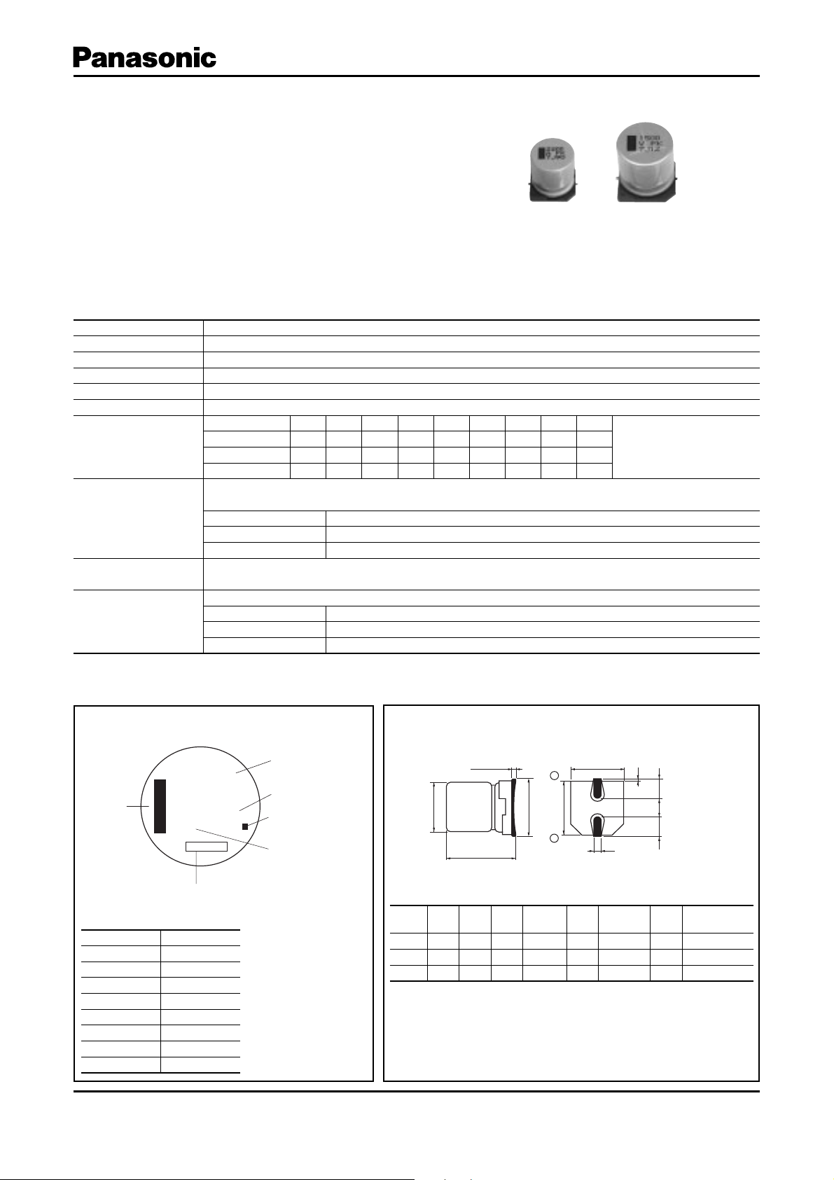
0.3 max.
A±0.2
W
( )reference size
L±0.5
φD±0.5
H
B±0.2
(I)
K
(P)
(I)
+
–
Surface Mount Type
Series:
Medium-size FK
High temperature Lead-Free refl ow(suffi x:A✽)
FK
■ Features
Endurance: 5000 h at 105 °C
●
Vibration-proof product is available upon request.
●
RoHS directive compliant
●
■ Specifi cations
Category Temp. Range –55 °C to +105 ° C
Rated W.V.Range 6.3 V. DC to 10 0 V.D C
Nominal Cap.Range 47 µF to 6800 µF
Capacitance Tolerance ±20 % (120 Hz/+20 °C)
DC Leakage Cur rent I < 0.01 CV (µA) After 2 minutes
tan
δ
W.V. (V) 6.3 10 16 25 35 50 63 80 100
Characteristics
at Low Temperature
Endurance
Shelf Life
Resistance to
Soldering Heat
Z(–25 °C)/Z(+20 °C)
Z(–40 °C)/Z(+20 °C)
Z(–55 °C)/Z(+20 °C)
After applying rated working voltage for 5000 hours at +105 °C±2 °C and then being stabilized at +20 °C,
Capacitors shall meet the following limits.
Capacitance change ±30 % of initial measured value
tan
δ
DC leakage current
After storage for 1000 hours at +105 °C±2 °C with no voltage applied and then being stabilized
at +20 °C, capacitors shall meet the limits specifi ed in Endurance (With voltage treatment)
After refl ow soldering and then being stabilized at +20 °C, capacitors shall meet the following limits.
Capacitance change ±10 % of initial measured value
tan
δ
DC leakage current
Typ e:
V
Please see the attached High temperature lead- free refl ow products list.
222222222
333333333
444333333
200 % of initial specifi ed value
<
initial specifi ed value
<
initial specifi ed value
<
initial specifi ed value
<
(Impedance ratio at 120 Hz)
■ Di men sions in mm (not to scale)■ Marking
Example:6.3 V 3300 µF Marking color : BLACK
Capacitance (µF)
3300
Series identification
Mark for Lead-Free
Products
Black Dot (Square)
Rated Voltage Mark
Size
code
DLA,BH max.I W P K
H13 12.5 13.513.5 15.0 4.7 0.90±0.3 4.4 0.70±0.3
J16 16.0 16.5 17.0 19.0 5.5 1.20±0.3 6.7 0.70±0.3
K16 1 8.0 16. 5 19 .0 2 1.0 6 .7 1.20±0. 3 6.7 0.70 ±0.3
Negative
polarity
marking (–)
Rated Voltage Mark
j6.3 V
A10 V
C16 V
E25 V
V35 V
H50 V
J63 V
K80 V
2A 100 V
Design and specifi cations are each subject to change without notice. Ask factory for the current technical specifi cations before purchase and/or use.
Should a safety concern arise regarding this product, please be sure to contact us immediately.
jFK
Lot number
(mm)
Jul. 2008
Page 2
Aluminum Electrolytic Capacitors/Medium-size FK
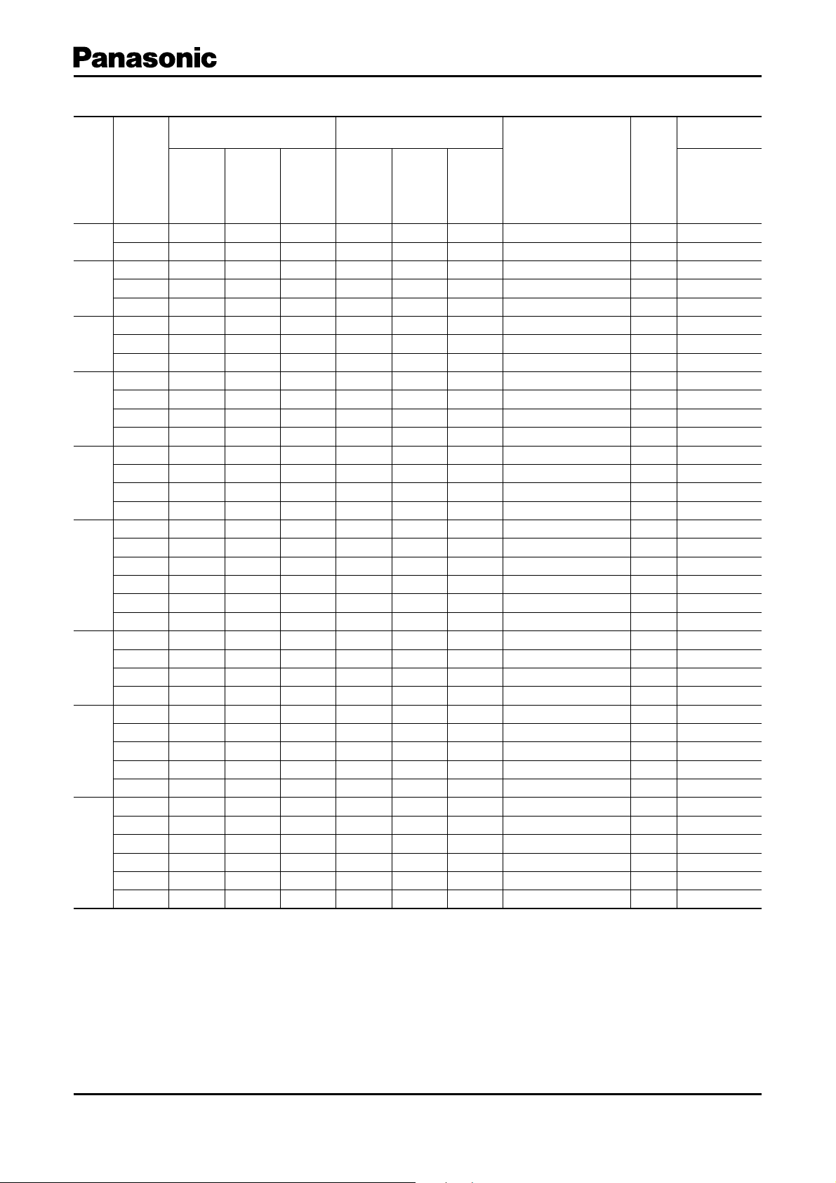
■ High temperature Lead-Free refl ow
Case size Specifi cation
W.V.
Cap.
(±20 %)
Dia. Length
Size
Code
Ripple
Current
(10 0 kHz)
(+105 °C)
(V) (µF) (mm) (mm)
6.3
3300 12.5 13.5 H1311000.06 0.30
6800 16 16.5 J16 180 0 0.035 0.36
(mA r.m.s.)
2200 12.5 13.5 H1311000.06 0.21
10
4700 16 16.5 J16 1800 0.035 0.25
6800 18 16.5 K16 2060 0.033 0.29
150 0 12.5 13.5 H1311000.06 0.16
16
3300 16 16.5 J16 1800 0.035 0.20
4700 18 16.5 K16 2060 0.033 0.22
1000 12.5 13.5 H13 1100 0.06 0.14
1500 16 16.5 J16 1800 0.035 0.16
25
2200 16 16.5 J16 1800 0.035 0.16
3300 18 16.5 K16 2060 0.033 0.18
470 12.5 13.5 H13 110 0 0.06 0.12
35
680 12.5 13.5 H13 1100 0.06 0.12
100 0 16 16.5 J16 1800 0.035 0.12
1500 16 16.5 J16 1800 0.035 0.12
330 12.5 13.5 H13 900 0.120.12
390 12.5 13.5 H13 900 0.120.12
50
470 16 16.5 J16 1610 0.073 0.12
560 16 16.5 J16 1610 0.073 0.12
680 16 16.5 J16 1610 0.073 0.12
100 0 16 16.5 J16 1610 0.073 0.12
150 12.5 13.5 H13 800 0.160.10
63
220 12.5 13.5 H13 800 0.160.10
470 16 16.5 J16 1410 0.082 0.10
680 18 16.5 K16 16 90 0.08 0.10
68 12.5 13.5 H135000.32 0.08
100 12.5 13.5 H13 500 0.32 0.08
80
150 12.5 13.5 H13 500 0.32 0.08
330 16 16.5 J16 793 0.17 0.08
470 18 16.5 K16 917 0.153 0.08
47 12.5 13.5 H135000.32 0.07
68 12.5 13.5 H135000.32 0.07
100
100 16 16.5 J16 793 0.17 0.07
150 16 16.5 J16 793 0.17 0.07
220 18 16.5 K16 917 0.153 0.07
330 18 16.5 K16 917 0.153 0.07
The taping dimensions are explained on p.177 of our Catalog. Please use it as a ref er ence guide.
Refl ow Profi le(Fig-1 to Fig-11) listed on p.175 of our Catalog.
Impedance
(10 0 kHz)
(+20 ° C)
tan
δ
(120 Hz)
(+20 ° C)
Part No.
(RoHS:compliant)
EEEFK0J332AQ
EEEFK0J682AM
EEEFK1A222AQ
EEEFK1A472AM
EEEFK1A682AM
EEEFK1C152AQ
EEEFK1C332AM
EEEFK1C472AM
EEEFK1E102AQ
EEEFK1E152AM
EEEFK1E222AM
EEEFK1E332AM
EEEFK1V471AQ
EEEFK1V681AQ
EEEFK1V102AM
EEEFK1V152AM
EEEFK1H331AQ
EEEFK1H391AQ
EEEFK1H471AM
EEEFK1H561AM
EEEFK1H681AM
EEEFK1H102AM
EEEFK1J151AQ
EEEFK1J221AQ
EEEFK1J471AM
EEEFK1J681AM
EEEFK1K680AQ
EEEFK1K101AQ
EEEFK1K151AQ
EEEFK1K331AM
EEEFK1K471AM
EEEFK2A470AQ
EEEFK2A680AQ
EEEFK2A101AM
EEEFK2A151AM
EEEFK2A221AM
EEEFK2A331AM
Endurance : 105 °C 5000 h
Min.
Packaging Q'ty
Refl ow
Tap ing
(pcs)
(9) 200
(9) 125
(9) 200
(9) 125
(9) 125
(9) 200
(9) 125
(9) 125
(9) 200
(9) 125
(9) 125
(9) 125
(9) 200
(9) 200
(9) 125
(9) 125
(10) 200
(10) 200
(10) 125
(10) 125
(10) 125
(10) 125
(10) 200
(10) 200
(10) 125
(10) 125
(11) 2 0 0
(11) 2 0 0
(11) 2 0 0
(11) 125
(11) 125
(11) 2 0 0
(11) 2 0 0
(11) 125
(11) 125
(11) 125
(11) 125
Design and specifi cations are each subject to change without notice. Ask factory for the current technical specifi cations before purchase and/or use.
Should a safety concern arise regarding this product, please be sure to contact us immediately.
Jul. 2008
Page 3

Aluminum Electrolytic Capacitors/ FK
Surface Mount Type
Series:
■ Features
Endurance: 2000 h at 105 °C
●
Low impedance (40 % to 60 % less than FC series)
●
Miniaturized (30 % to 50 % less than FC series)
Vibration-proof product is available upon request. (φ8 <)
●
RoHS directive compliant
●
■ Specifi cations
Category Temp. Range –55 °C to +105 ° C
Rated W.V.Range 6.3 V. DC to 3 5 V. DC
Nominal Cap.Range 4.7 µF to 1500 µF
Capacitance Tolerance ±20 % (120 Hz/+20 °C)
DC Leakage Cur rent I < 0.01 CV or 3 (µA) After 2 minutes (Whichever is greater)
tan
δ
Characteristics
at Low Temperature
Endurance
Shelf Life
Resistance to
Soldering Heat
Typ e:
FK
High temperature Lead-Free refl ow(suffi x:A✽)
FK
V
Please see the attached High temperature lead- free refl ow products list.
W.V. (V) 6.3 10 16 25 35
Z(–25 °C)/Z(+20 °C) 22222
Z(–40 °C)/Z(+20 °C) 33333
Z(–55 °C)/Z(+20 °C) 44433
After applying rated working voltage for 2000 hours at +105 °C±2 °C and then being stabilized at +20 °C,
Capacitors shall meet the following limits.
Capacitance change ±30 % of initial measured value
tan
δ
DC leakage current
After storage for 1000 hours at +105 °C±2 °C with no voltage applied and then being stabilized
at +20 °C, capacitors shall meet the limits specifi ed in Endurance. (With voltage treatment)
After refl ow soldering and then being stabilized at +20 °C, capacitor shall meet the following limits.
Capacitance change ±10 % of initial measured value
tan
δ
DC leakage current
200 % of initial specifi ed value
<
initial specifi ed value
<
initial specifi ed value
<
initial specifi ed value
<
(Impedance ratio at 120 Hz)
■ Di men sions in mm (not to scale) ■ Marking
Example:6.3 V 22 µF
Marking color : BLACK
Negative polarity
marking (–)
Capacitance (µF)
22
Series identification
jFK
Lot number
Rated Voltage Mark
j6.3 V
A10 V
C16 V
E25 V
V35 V
Design and specifi cations are each subject to change without notice. Ask factory for the current technical specifi cations before purchase and/or use.
Should a safety concern arise regarding this product, please be sure to contact us immediately.
Mark for Lead-Free
Products Black Dot
(Square)
Rated Voltage Mark
Size
code
B4.05.84.35.5 1.8 0.65±0.1 1.0 0.35– 0.20 to +0.15
C5.05.85.36.52.20.65±0.1 1.5 0.35 –0.20 to +0.15
D6.35.86.67.82.60.65±0.11.80.35–0.20 to +0.15
D8 6.3 7.7 6.6 7.8 2.6 0.65±0.1 1.8 0.35–0.20 to +0.15
E8.06.28.39.53.40.65±0.1 2.2 0.35– 0.20 to +0.15
F8.010.28.310.0 3.40.90 ±0.2 3.1 0.70±0.2
G10.010.2 10.3 12.0 3.5 0.9 0±0.2 4.6 0.70±0.2
0.3 max.
H
φD±0.5
L±0.3
DLA,BH max.I W P K
A±0.2
–
B±0.2
+
( )reference size
K
W
(I)
(P)
(I)
(mm)
Jul. 2008
Page 4

Aluminum Electrolytic Capacitors/ FK
■ High temperature Lead-Free refl ow
Endurance : 105 °C 2000 h
Case size Specifi cation
W.V.
Cap.
(±20 %)
Dia. Length
Size
✽
Code
(V) (µF) (mm) (mm)
22 45.8B901.350.26
4 5.8 (B) 90 1.35 0.26
47
5 5.8 C 160 0.70 0.26
5 5.8 (C) 160 0.70 0.26
100
6.3 5.8 D 240 0.36 0.26
6.3
220 6.3 5.8 D 240 0.36 0.26
6.3 7.7 D8 280 0.34 0.26
330
8 6.2 E 300 0.26 0.26
470 8 10.2F6000.160.26
1000 8 10.2F6000.160.26
1500 10 10.2 G 850 0.08 0.26
22 45.8B901.350.19
4 5.8 (B) 90 1.35 0.19
33
5 5.8 C 160 0.70 0.19
150 6.3 5.8 D 240 0.36 0.19
10
6.3 7.7 D8 280 0.34 0.19
220
8 6.2 E 300 0.26 0.19
330 8 10.2F6000.160.19
470 8 10.2F6000.160.19
680 8 10.2F6000.160.19
100 0 10 10.2 G 850 0.08 0.19
10 45.8B901.350.16
4 5.8 (B) 90 1.35 0.16
22
5 5.8 C 160 0.70 0.16
5 5.8 (C) 160 0.70 0.16
47
6.3 5.8 D 240 0.36 0.16
68 6.3 5.8 D 240 0.36 0.16
16
100 6.3 5.8 D 240 0.36 0.16
150 6.3 7.7 D8 280 0.34 0.16
6.3 7.7 D8 280 0.34 0.16
220
8 6.2 E 300 0.26 0.16
330 8 10.2F6000.160.16
470 8 10.2F6000.160.16
680 10 10.2 G 850 0.08 0.16
10 45.8B901.350.14
22 5 5.8 C 160 0.70 0.14
5 5.8 (C) 160 0.70 0.14
33
6.3 5.8 D 240 0.36 0.14
47 6.3 5.8 D 240 0.36 0.14
25
68 6.3 5.8 D 240 0.36 0.14
100 6.3 7.7 D8 280 0.34 0.14
8 6.2 E 300 0.26 0.14
150 8 10.2F6000.160.14
220 8 10.2F6000.160.14
330 8 10.2F6000.160.14
470 10 10.2 G 850 0.0 8 0.14
4.7 4 5.8 B 90 1.35 0.12
4 5.8 (B) 90 1.35 0.12
10
5 5.8 C 160 0.70 0.12
22 5 5.8 C 160 0.70 0.12
33 6.3 5.8 D 240 0.36 0.12
35
47 6.3 5.8 D 240 0.36 0.12
68 6.3 7.7 D8 280 0.34 0.12
100 8 10.2F6000.160.12
150 8 10.2F6000.160.12
220 8 10.2F6000.160.12
330 10 10.2 G 850 0.08 0.12
Size code( ):Miniaturization product
✽
If Part number exceeds 12 digits, voltage code is abbreviated as follows; 0J씮J, 1A씮A, 1C씮C, 1E씮E, 1V씮V
The taping dimensions are explained on p.177 of our Catalog. Please use it as a ref er ence guide.
Refl ow Profi le(Fig-1 to Fig-11) listed on p.175 of our Catalog.
Ripple
Current
(10 0 kHz)
(+105 °C)
(mA r.m.s.)
Impedance
(10 0 kHz)
(+20 ° C)
tan
δ
(120 Hz)
(+20 ° C)
Part No.
(RoHS:compliant)
EEEFK0J220AR
EEEFKJ470UAR
EEEFK0J470AR
EEEFKJ101UAR
EEEFK0J101AP
EEEFK0J221AP
EEEFKJ331XAP
EEEFK0J331AP
EEEFK0J471AP
EEEFK0J102AP
EEEFK0J152AP
EEEFK1A220AR
EEEFKA330UAR
EEEFK1A330AR
EEEFK1A151AP
EEEFKA221XAP
EEEFK1A221AP
EEEFK1A331AP
EEEFK1A471AP
EEEFK1A681AP
EEEFK1A102AP
EEEFK1C100AR
EEEFKC220UAR
EEEFK1C220AR
EEEFKC470UAR
EEEFK1C470AP
EEEFK1C680AP
EEEFK1C101AP
EEEFKC151XAP
EEEFKC221XAP
EEEFK1C221AP
EEEFK1C331AP
EEEFK1C471AP
EEEFK1C681AP
EEEFK1E100AR
EEEFK1E220AR
EEEFKE330UAR
EEEFK1E330AP
EEEFK1E470AP
EEEFK1E680AP
EEEFKE101XAP
EEEFK1E101AP
EEEFK1E151AP
EEEFK1E221AP
EEEFK1E331AP
EEEFK1E471AP
EEEFK1V4R7AR
EEEFKV100UAR
EEEFK1V100AR
EEEFK1V220AR
EEEFK1V330AP
EEEFK1V470AP
EEEFKV680XAP
EEEFK1V101AP
EEEFK1V151AP
EEEFK1V221AP
EEEFK1V331AP
Refl ow
Min.
Packaging Q'ty
Tap ing
(pcs)
(5) 2000
(5) 2000
(5) 1000
(5) 1000
(5) 1000
(5) 1000
(5) 900
(6) 1000
(6) 500
(6) 500
(6) 500
(5) 2000
(5) 2000
(5) 1000
(5) 1000
(5) 900
(6) 1000
(6) 500
(6) 500
(6) 500
(6) 500
(5) 2000
(5) 2000
(5) 1000
(5) 1000
(5) 1000
(5) 1000
(5) 1000
(5) 900
(5) 900
(6) 1000
(6) 500
(6) 500
(6) 500
(5) 2000
(5) 1000
(5) 1000
(5) 1000
(5) 1000
(5) 1000
(5) 900
(6) 1000
(6) 500
(6) 500
(6) 500
(6) 500
(5) 2000
(5) 2000
(5) 1000
(5) 1000
(5) 1000
(5) 1000
(5) 900
(6) 500
(6) 500
(6) 500
(6) 500
Design and specifi cations are each subject to change without notice. Ask factory for the current technical specifi cations before purchase and/or use.
Should a safety concern arise regarding this product, please be sure to contact us immediately.
Jul. 2008
 Loading...