

Page 1
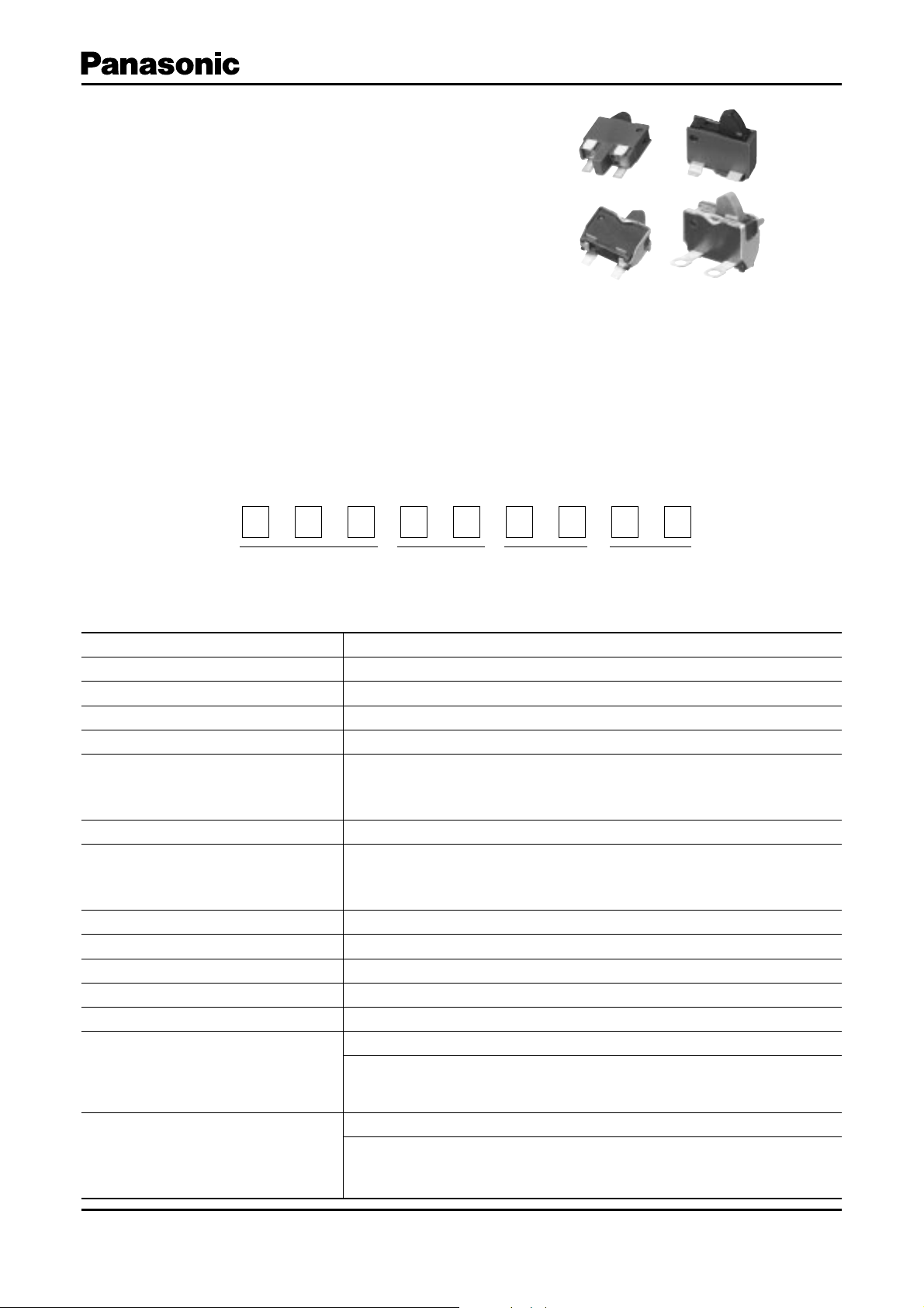
2N Detector Switches
Typ e:
ESE22
Detector Switches/ESE22
■ Features
● Can be operated with different actuation angles
(horizontally and vertically)
■ Recommended Applications
● Detection of media in portable electronic equipment
● Refl ow soldering
● Light operating force
■ Explanation of Part Numbers
1
E
2
S
Product Code
3456789
E
22
Type
Style
Design No.
■ Specifi cations
Rating 50 µA 3 Vdc to 10 mA 5 Vdc (Resistive load)
Contact Resistance 500 m액 max.
Insulation Resistance 100 M액 min. (100 Vdc)
Dielectric Withstanding Voltage 100 Vac for 1 minute
Operating Force 300 mN max.
Mounting Height
Poles and Throws 1-pole 1-throw
Full Travel (Pushing distance)
Operating Life 50000 cycles min.
Temperature Range –10 °C to +70 °C
Heat Resistance +80 °C for 96 hours
Low Temperature Resistance –25 °C for 96 hours
Humidity Resistance +40 °C 90 % to 95 % RH for 96 hours
Minimum Quantity/Packing Unit
Quantity/Carton
Design and specifi cations are each subject to change without notice. Ask factory for the current technical specifi cations before purchase and/or use.
Should a safety concern arise regarding this product, please be sure to contact us immediately.
· Type MV 4.1 mm · Type MH 2.1 mm
· Type MH
· Type MV 4.25 mm(2.05 mm) · Type MH 1.2 mm(2.0 mm)
· Type MH
500 pcs. Polyethylene Bag (Bulk)
· Type MV
· Type MH with Frame
· Type MH
10000 pcs. Polyethylene Bag (Bulk)
· Type MV
· Type MH with Frame
· Type MH
with Frame
with Frame
1000 pcs. Embossed Taping (Reel Pack)
6000 pcs. Embossed Taping (Reel Pack)
2.85 mm
0.6 mm(2.0 mm)
3000 pcs. Embossed Taping (Reel Pack)
4000 pcs. Embossed Taping (Reel Pack)
180 00 pcs. Embossed Taping (Reel Pack)
24000 pcs. Embossed Taping (Reel Pack)
Jun. 2008
Page 2
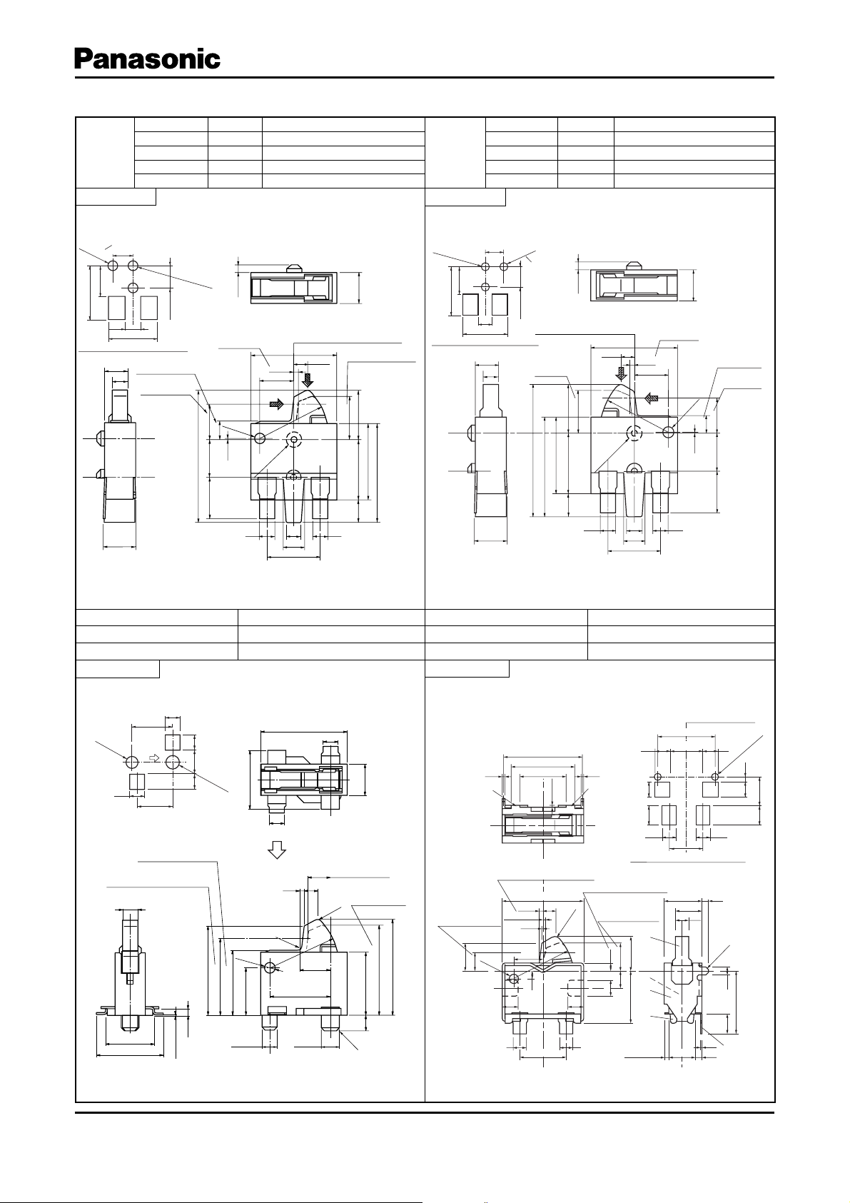
■ Dimensions in mm (not to scale)
0.35 max.
0.1 min.
0.1
2
6.15
1.3
2.1
0.6
–0.2
+0.3
2.63.95
3.5
1
0.6
0.18±0.25
1.4
1.2
2.2
φ0
.7
1.2
1.2
0.28
0.08
(2.1)
0.5
1
0.98
R
4.55
R0.45
2.85 0.5
0.6
4.75
1.5
C0.2
2
1±0.1
5
4
3
1
2
5.95
0.2 0.2
3.5
4.8
Vertical direction
ON starting position
Horizontal ON position
measuring point
Full stroke position
Part A
Part A
Horizontal ON starting
position
5.95
Center of on start position
in case of horizontal operation
PWB mounting hole for reference
(Tolerance:±0.05)
(Scale:1/2)
3.5
3.5
2
-
φ0.7
+0.05
(
Hole
)
0
0.5
1.6
1.6
2.0
1.4
1.6 1.6
2.0 2.95
1.4
Part Numbers H : boss Packaging
ESE22MH21
Type
ESE22MH27
ESE22MH22
ESE22MH27T
No. 1
(The hole for flux prevention)
φ1.1 hole
2.2
3.5
6.0
1.7
PWB mounting hole for reference
1.45
1.0
1-pole 1-throw
5.3
Full stroke
position
Horizontal
ON position
measuring
position
φ1.1
2.5±0.1
2.1 max.
0.5 Polyethylene Bag (Bulk)
1.0 Polyethylene Bag (Bulk)
0.5 Embossed Taping (Reel Pack)
1.0 Embossed Taping (Reel Pack)
+0.
0
5
0
hole
H
ON starting
position
0.26
2.2
(φ0.7)
2.3
1.2
0.05
2.5
(8.65)
0.05
±
.00
1
2-φ
2.7
1.0
1.9
Boss center
ON starting position standard
5.7
R4.5
0.88
Vertical direction
ON starting position
3.2
2.8
5.0
3.95
6.5
1.5
1.0
1.4
3.5
1.0
Part Numbers H : boss Packaging
ESE22MH23
Type
ESE22MH28
ESE22MH24
ESE22MH28T
No. 2
2φ1
+
0
.
.
05
1
0
hole
3.5
6.0
PWB mounting hole for reference
1-pole 1-throw
2.2
φ1.1
2.5±0.1
1.7
5.3
1.45
Vertical direction
ON starting position
1.0
hole
(The hole flux
prevention)
2.1 max.
Detector Switches/ESE22
0.5 Polyethylene Bag (Bulk)
1.0 Polyethylene Bag (Bulk)
0.5 Embossed Taping (Reel Pack)
1.0 Embossed Taping (Reel Pack)
H
Boss center
ON starting position standard
0.88
2.8
1.0
2-φ1.00
±
R4.5
.05
0
1.0
1.4
3.5
(8.65)
6.5
5.0
3.2
3.95
1.5
5.7
0.26
ON starting
position
2.2
1.0
φ0.7)
(
1.9
0.05
1.2
2.3
2.5
2.7
Full stroke
position
Horizontal
ON position
measuring
position
Part Numbers Packaging Part Numbers Packaging
ESE22MV21
ESE22MV21T
No. 3
Polyethylene Bag (Bulk)
Embossed Taping (Reel Pack)
1-pole 1-throw
ESE22MH51
ESE22MH52
No. 4
Polyethylene Bag (Bulk)
Embossed Taping (Reel Pack)
1-pole 1-throw
With Frame Type
1.4
φ1.1
Operating
+
0
1.4
.1
0
direction
3.5
1.51.5 2.4
φ1.3
+0.
1
0
3.8
PWB mounting hole for reference
4.0
(View from
Design and specifi cations are each subject to change without notice. Ask factory for the current technical specifi cations before purchase and/or use.
Should a safety concern arise regarding this product, please be sure to contact us immediately.
A direction, SCL=1/2)
Pushable height
Horizontal ON position
measuring position
±0.11.0
3.4
4.4
0.13 max.
(φ
0.7)
5.85
5.1
4.25
0.45
(3.1)
0
φ1.0
-0.1
1.0
A
0.2
R0.1
5.7
(4.0)
φ1.2
±0.1
1.5
0.88
1.95
-0.1
±0.3
R4.5
0
1.0
R0.
ON starting
position
ON starting
position
3
C0.2
±0.1
1.9
4.1
1.0
±0.3
5.9
±0.3
6.3
Jan. 2008
Page 3

■ Dimensions in mm (not to scale)
Common
terminal
Common
terminal
C
C
Part Numbers Packaging Part Numbers Packaging
ESE22MH53
ESE22MH54
No. 5
1-pole 1-throw
With Frame Type
Part A
Vertical direction
ON starting position
Full stroke position
–0.2
+0.3
0.6
2.6
(2.1)
1.3
1.2
3.95
1.2 1.2
11
R0.45
R
5.95
4.8
3.5
0.1 min.
Horizontal ON starting
position
6.15
0.28
0.98
0.18±0.25
0.08
4.55
2.2
0.6
3.5
Polyethylene Bag (Bulk)
Embossed Taping (Reel Pack)
0.20.2
Part A
Horizontal ON position
measuring point
7
φ0.
1.4
0.35 max.
2.1
Detector Switches/ESE22
ESE22MH57
No. 6
1-pole 1-throw
Solder lug Type
5.95
4.8
0.2 0.2
Part A
0.52.85
2
1±0.1
1
4
5
2
C0
0.6
.2
4.75
Horizontal on position
measuring point
φ0.7
2.1
1.4
Part A
1.5
0.1
3
0.5
2
3.5
0.1min.
1.61.6
3.5
Horizontal on starting
position
6.15
0.28
0.08
2.2
0.98
R0.45
R4.55
0.18±0.25
0.6
Polyethylene Bag (Bulk)
Part A
3.35
4.15
2-φ1
Full stroke position
Vertical direction
ON starting position
–0.2
+0.3
0.6
2.6
(2.1)
1.3
1.2
1.21.2
Part A
3.95
0.1
3
1
4
5
1±0.1
2.85 0.5
2
C0.2
Part A
0.5
2
0.6
2
No. 7
Solder lug Type
Vertical direction
ON starting position
Full stroke position
–0.2
+0.3
2.6
(2.1)
1.3
3.95
Part Numbers Packaging
ESE22MH58
Polyethylene Bag (Bulk)
1-pole 1-throw
5.95
4.8
3.5 0.20.2
Part A
Part A
0.6
1.2
1.2 1.2
R0.4
1.6
5
R4.55
6.15
0.98
3.5
0.28
0.1 min.
0.18±0.25
0.08
Part A
φ1
2-
1.6
Horizontal operation
ON starting position
Horizontal ON position
measuring point
2.2
7
.
φ0
Part A
0.6
3.35
4.15
1.4
3
0.1
2.1
1
■ Circuit Diagram
1-pole 1-throw (N.O)
■ Packaging Specifi cations
Standard Reel Dimensions in mm (not to scale)
0.52.85
2
1±0.1
C0.2
4
Part A
5
2
0.5
2
Tap ing Re el Embos sed Ca rrier Taping
0.6
φ380.0±2.0
16.4
2.0
ESE22MH
2.0
7.5±0.1
1.75±0.1
16.0±0.3
ESE22MV
7.9 0.4
1.75±0.1
7.5
16.0±0.3
Carrier tape
Non-packed portion
(160 mm min.)
φ1.5
+0.1
0
Carrier tape
10.0
Non-packed portion
(160 mm min.)
P=8.0±0.1
φ1.5
+0.1
0
Packed portion
P=12.0±0.1
4.0±0.1
2.0±0.1
Packed portion
Insert direction of switch
Drawing direction
4.0±0.1
2.0±0.1
Pilot holes
Drawing direction
Pilot holes
Leading portion 400 mm min.
Non-packed portion
Leading portion 400 mm min.
Non-packed portion
(100 mm min.)
(100 mm min.)
TOPEND
TOPEND
Cover tape
Cover tape
13.5
13.5
Design and specifi cations are each subject to change without notice. Ask factory for the current technical specifi cations before purchase and/or use.
Should a safety concern arise regarding this product, please be sure to contact us immediately.
Nov. 2005
 Loading...