

Page 1
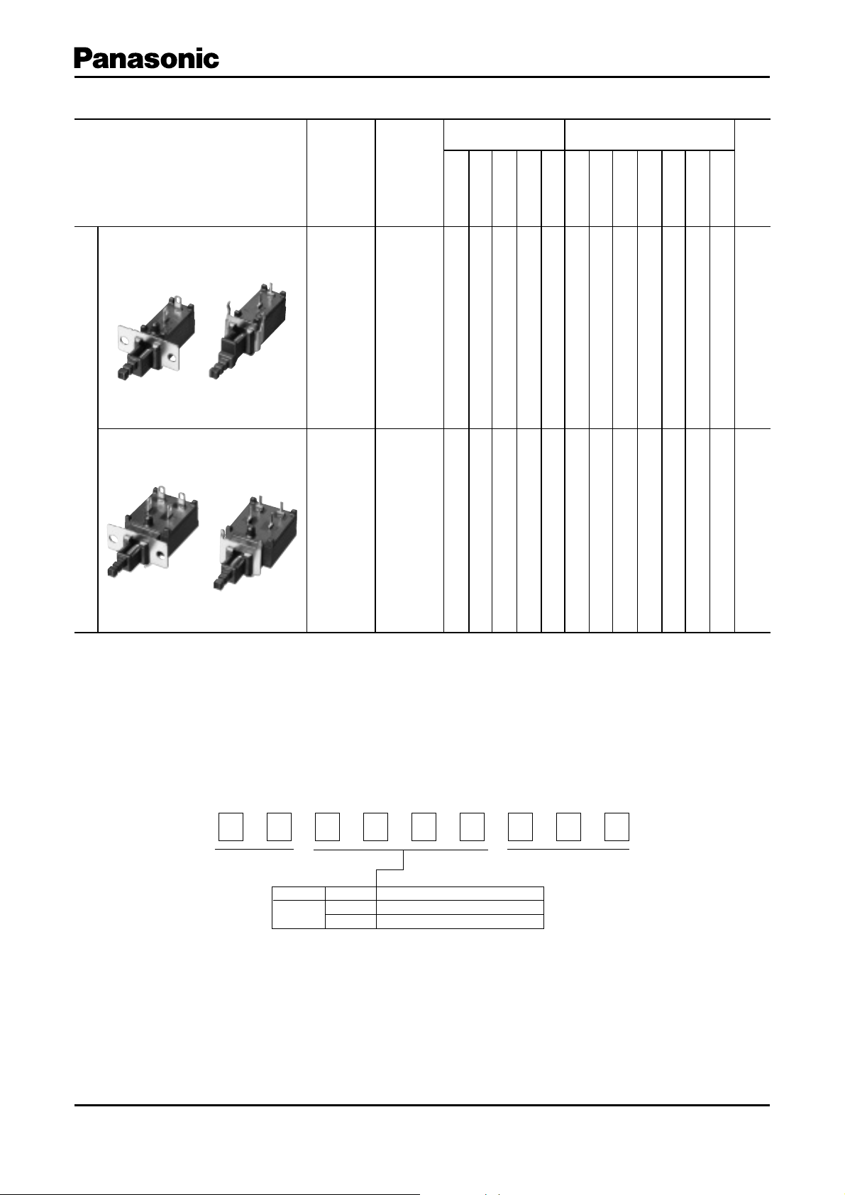
Quick Selection Guide
■
Type
ESB92S
OperationTravel
Power Switches
Circuit Diagram Acquired Standard
S
S
D
D
P
P
P
D
S
T
T
P
D
S
T
T
ULC
✽
S
V
D
E
S
A
M
E
K
Others
O
B
E
Page
A
B
Others
Push
ESB92D
Series R
Push
Power switches described here are not under jurisdiction of the Electrical Appliance and Material Safety Law, but comply with its technical
✽
re quire ments.
1.5 mm
2.5 mm
1.5 mm
2.5 mm
쑗
쑗
✽
쑗쑗쑗쑗쑗 쑗
✽
쑗쑗쑗쑗쑗 쑗
13
16
Explanation of Part Numbers
■
1
E
Product Code Design No.
Design and specifi cations are each subject to change without notice. Ask factory for the current technical specifi cations before purchase and/or use.
Should a safety concern arise regarding this product, please be sure to contact us immediately.
2 3 4 56789
S
3th
B
4th,5th,6th
92S
92D
Compact Push Type (SPST)
Compact Push Type (DPST)
Type
Jan. 2006
Page 2

Product Consolidation
■
Power Switches
●
Type ESB82
PWB Mount Type 1
PWB Mount Type 2
Solder lug Type
●
Type ESB92S
Rating TV-5, 5 A 250 V ac
4 A/128 A 250 V ac
PWB Mount Type 1
PWB Mount Type 2
Solder lug Type
●
Type ESB99
●
Type ESB91
PWB Mount Type
Type ESB99 Type ESB91
Solder lug Type
Type ESB99 Type ESB91
●
Type ESB92D
Rating TV-5, 5 A 250 V ac
4 A/128 A 250 V ac
PWB Mount Type
Solder lug Type
Design and specifi cations are each subject to change without notice. Ask factory for the current technical specifi cations before purchase and/or use.
Should a safety concern arise regarding this product, please be sure to contact us immediately.
Nov. 2005
Page 3
Power Switches
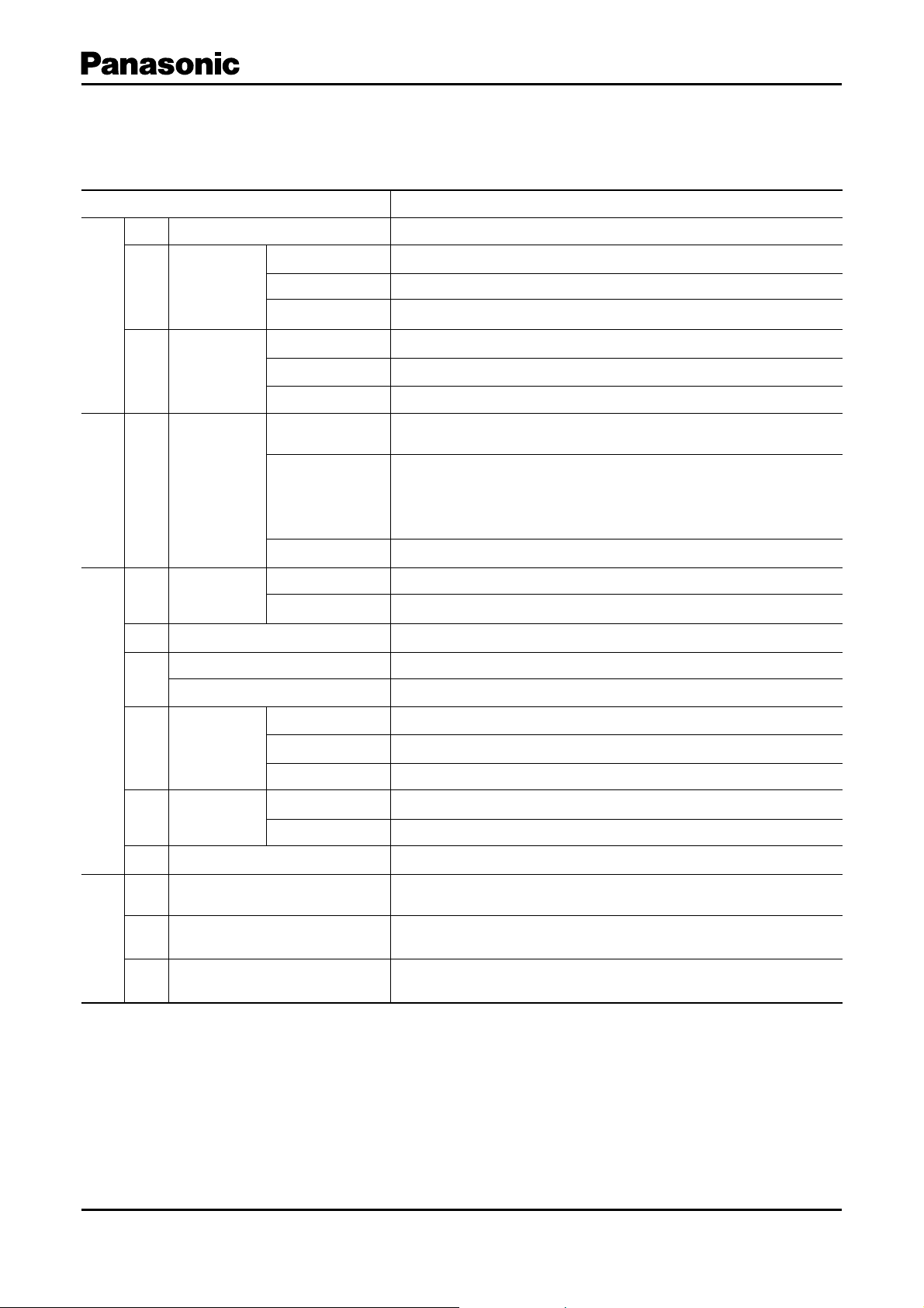
Checklist Before lnquiry
■
When specifying Power Switches, please take advantage of our standard products for better price and delivery.
Please inquire about the following items before ordering.
Item Information (Requirements)
C-1 Inquiry purpose New use, Modifi cation, Others ( )
Previous supplier
C-2 Modifi cation
Conventional part No.
Purpose
Common
C-3 Application
Equipment
Environment Indoor/Outdoor use, Stationary/Portable set, High humidity, SO
Temperature ( °C) to ( °C)
UL
CSA
SEMKO DEMKO
✽
VDE NEMKO
BEAB FIMKO
SEV (SETI)
4 A/128 A 250 Vac
(Based on IEC standards)
Regulations
S-1
Safety
Standards
(Ratings)
Others
Operation type Push type, Others ( )
M-1 Operation
Operating force When specially requested ( N)
M-2 Circuit Diagrams SPST, DPST
Lever length (Push type) 18.0 mm
M-3
Travel (Push type)1.5 mm, 2.5 mm
Mounting holes 2-M3҂0.5 Tap, 2-f3.2 hole W/O Mounting Plate, Others ( )
TV-5
2
, NaCl
M-4 Mounting
Shapes/ Dimensions
Supporting legs Necessary (PWB mount type, Solder lug type), Unnecessary
Mounting height PWB to center of rod
Shape PWB, Solder lug, Others ( )
M-5 Terminals
Connection Manual soldering, Wave soldering
M-6 Lever top dimensions Width ( mm) ҂ Height ( mm) ҂ Length ( mm)
L-1 Special requirements for endurance
L-2 Special requirements for safety
Others
L-3 Other questionnaires
Power switches described here are not under jurisdiction of the Electrical Appliance and Material Safety Law (Japan), but comply with its
✽
tech ni cal requirements.
Notes:
1. Whe n you sp ecif y custom types (custom -made), new too ling and jigs, and/or equipment may be required. It will be necess ary to confi rm your
estimates of quantity and development schedule as accurately as possible.
2. Please inform us if you designate your own part number.
Design and specifi cations are each subject to change without notice. Ask factory for the current technical specifi cations before purchase and/or use.
Should a safety concern arise regarding this product, please be sure to contact us immediately.
Nov. 2005
Page 4

Power Switches
(2.5)
(3.0)
(3.3)
(0.6)
Switch rod top
Customer's
button
(0.6)
(R1.2)
Application
■
When using our Power Switches, please observe the fol low ing
items (“prohibited items”) and be cautious of the fol low ing
in or der to prevent dangerous ac ci dents and de te ri o ra tion
of per for mance.
1. Prohibited items and notes on mounti ng
1. Operation position for soldering (including pre heat ing)
Push type switches: Do not solder in the locked con di tion.
Slide type switches: Be sure to switch the lever se cure ly
when soldering.
2. When soldering using a soldering iron, soldering con di tions
vary with the tip shape of the soldering iron, watt age,
and PWB thickness. Thoroughly check the con di tions
in ad vance, including the heat re sis tance rat ing of the
solder.
3. Do not apply a load to terminals when soldering. Care
should be taken in this regard because a load may
deteriorate electric and mechanical characteristics.
4. Since the power switches are not sealed, do not wash
them.
5. When mounting a power switch to a through-hole type
PWB, the infl uence of thermal stress on the switch is
greater than that on one-sided PW B.
Be sure to check the infl uence as well as the heat
re sis tance rating of the solder.
2. Notes on circuit conditions
When a power switch is used with a weak current of less
1.
than 500 mA, the fi lm on the surface of con tact cannot
be bro ken and contact failure may oc cur.
2. The durability of power switches varies with the type
of the switch: those for ac power and those for dc
pow er. When using switches for ac power, check the
durability. When us ing switches for dc power, re view
and check the load conditions of a relevant set.
3. Use the switches within their rating, including in rush
current rating. Check particularly the inrush current
using a switch with a set. Since voltage fl uc tuation
occurs depending on geographical re gion, review the
derating for using a switch.
If load conditions vary in a set to be used, adapt ability
4.
with the switch must be considered. Be sure to check
the above mentioned notes 1 to 3.
3. Prohibited items and notes on mounting and op er at ing
con di tions
1. In pri ncip le, oper ate the center of the lever.
2. For mounting an operation button:
1) Design so that the button is mounted to the cen ter
of the lever.
2) Design so that the load in removal and mount ing of
the button is within the range of the switch’s strength
rating of the o perational part.
3. Do not pull the switch rod while it is locked. Oth er wise,
the self-lock ing func tion may be broken, re sult ing in a
lock ing fail ure or mal func ti on. Make sure that the switch
is re leased es pe cial ly when attaching/de tach ing a but ton
to the rod and as sem bling/ dis as sem bling the target
prod uct. (This ap plies to the self- lock ing switches) Set
the strength for de tach ing your but ton (knob) from our
switch rod to a max i mum of 10 N in order to minimize
Design and specifi cations are each subject to change without notice. Ask factory for the current technical specifi cations before purchase and/or use.
Should a safety concern arise regarding this product, please be sure to contact us immediately.
Notes
Button
Lever
the pos si bil i ty of a break down of the locking func tion.
When de sign ing your but ton, re fer to the followi ng
shape and dimensions.
Before adopting our switches, check the requirements
carefully.
Reference of Customer's button design
4. When mounting a switch to a set, check the switch
ON/OFF setting and the position of the op er a tion al part
(slide t ype, rotary type, etc.).
5. Desi gn an d use so that external stress is not
continuously applied to the soldering parts (solder lugs
and PWB terminals) with a switch mounted in a set.
6. In actual operating conditions, do not use switch es
un der ambient temperatures above 70 °C.
7. Avoid the following ambient surroundings and oth er
con di tions because they may affect per for mance:
Under an atmosphere of corrosive gas such as Cl
●
2
S, NOx, or SO
H
In atmospheres of residual water drops, dew
●
con den sa tion, or adhesive water drops
In liquids such as water, salt solution, oil, chem i cals,
●
and organic solvents
In direct sunlight
●
In dust y locations
●
4. Prohibited ite ms and notes on storage c on di tions
Since contact characteristics and soldering quality may
de te ri o rate due to sulfuration and oxidation of con tacts
and ter mi nals, pay heed to the following items.
1. For storage and transport of the switches, avoid
unpacking them, and store them at room tem per a ture
and room humidity. Use them as soon as pos si ble,
gen er al ly with in 3 months, or within a max i mum of 6
months after de liv ery.
2. Do not store the switches under conditions of high
tem per a ture and/or high humidity, or in a location
where cor ro sive gas may be generated.
3. If some units remain after unpacking, store them af ter
applying adequate moisture-proof and gas-proof
treat ment.
5. For use in equipment for which safety re quest ed
Although care is taken to ensure switch quality,
vari a tion of contact resistance (increase), short
cir cuits, open cir cuits, and temperature rise are
some prob lems that might be generated.
To de sign a set which places maximum emphasis
on safety, review the affect of any single fault of
a switch in advance and perform virtually fail-safe
design to ensure maximum safety by:
1. pr ep ar in g a protective circuit or a protective
de vice to improve system safety, and
2. preparing a redundant circuit to improve sys tem
safety so that the single fault of a switch does
not cause a dangerous situation.
6. For actual use, be sure to refer to “Product Spec i fi ca tions
for Information.”
2
Mar. 2005
2
,
Page 5

Indications of Safety Standard
LL2
■
Power Switches
UL U.S.A
CSA Canada
SEMKO Sweden
VDE Germany
SEV Switzerland
BEAB U.K
DEMKO Denmark
NEMKO Norway
FIMKO Finland
WO
BEAB
Design and specifi cations are each subject to change without notice. Ask factory for the current technical specifi cations before purchase and/or use.
Should a safety concern arise regarding this product, please be sure to contact us immediately.
Mar. 2005
Page 6

Standard Products
■
Power Switches
Series
Series R1
Part
Numbers
ESB92S27B
ESB92S17B
ESB92S28B
ESB92S18B
ESB92S21B
ESB92S Type
ESB92S11B
ESB92S81B
ESB92S9 4 B
ESB92S22B
ESB92D27B
Cir cuit
SPST
SPST No.1-a
SPST –
SPST –
SPST No.2
SPST No.2-a
SPST No.3
SPST No.3-a
SPST –
DPST
Power
Rating
TV-5
5 A 250 V ac
4 A/128 A
250 V ac
Acguired
Safety
Stan dard
UL
CSA
SEMKO
VDE
BEAB
SEV
DEMKO
NEMKO
FIMKO
Shape
No.1
No.1
Terminal Type
Solder
PWB
Lug
Mount
●●
●●
●●
●●
●●
Lock Travel
(mm)
1.5 mm 2.5 mm
●●
●●
●●
●●
●●
Mounting
height
from PWB
to lever
(mm)
6.5 mm
6.5 mm
6.5 mm
6.5 mm
6.5 mm
6.5 mm
12. 5 mm
12. 5 mm
6.5 mm
6.5 mm
M3
Tap
●
●
Mounting Spec.
f
3.2 Hole
f
3.2
Self Standing
Hole
Type
●
●
●
●
W/O Plate
Self Standing
Type
●
●
●
●
Page
13
ESB92D17B
ESB92D28B
ESB92D18B
ESB92D21B
Series R2
ESB92D Type
ESB92D11B
ESB92D22B
ESB92D12B
Minimum Quantity/Packing Unit
■
DPST No.1-a
DPST –
TV-5
DPST –
5 A 250 V ac
4 A/128 A
DPST No.2
250 V ac
DPST No.2-a
DPST –
DPST –
UL
CSA
SEMKO
VDE
BEAB
SEV
DEMKO
NEMKO
FIMKO
●●
●●
●●
●●
●●
●●
●●
Please place an order by an integer multiple of the Quantity/Car ton.
6.5 mm
6.5 mm
6.5 mm
6.5 mm
6.5 mm
6.5 mm
6.5 mm
●
●
●
16
●
●
●
●
Produ ct Item (Se ries, Ty pe ) Pa r t N o. Pa c ka gi n g
ESB92S
Series: R, Typ e E SB 9 2
ESB92D
Design and specifi cations are each subject to change without notice. Ask factory for the current technical specifi cations before purchase and/or use.
Should a safety concern arise regarding this product, please be sure to contact us immediately.
Polyethylene Bag
(Bulk)
Quantity/Carton
(Export)
600 pcs.
(1800 pcs.)
300 pcs.
(900 pcs.)
Min. Q’ty/
Packi ng Unit
50 pcs.
25 pcs.
Notes
Jan. 2006
Page 7

Common Specifi cations for Push Type Power Switches (Series R)
Type:
ESB92
■ Mechanical Specifi cations
Power Switches/ESB92
Ter m ina l S t ren gt h
Lever Strength To withstand 50 N push force applied along the lever for 1 minute
Lever Wobble 1 mm max. in any direction at the lever top
Contact Pressure 300 mN min.
To w ithstand 10 N push force applied at the terminal top in any direction for
1 minute without damage or loosening
■ Electrical Specifi cations and Operating Temperature
Contact Resistance After several non-loaded operations: 50 m액 ma x. (at 1 A 5 Vdc )
Insulation Resistance Terminal to Terminal, Terminal to Frame: 100 M액 min. at 500 Vdc
Dielectric Withstanding
Voltage
As per applicable Safety Standard
Operating Temperature –10 °C to +6 0 °C
Design and specifi cations are each subject to change without notice. Ask factory for the current technical specifi cations before purchase and/or use.
Should a safety concern arise regarding this product, please be sure to contact us immediately.
Mar. 2005
 Loading...