

a
b
t
W
L
Metal Film Chip Resistors,
High Reliability Type
0402, 0603, 0805, 1206
Typ e:
ERA 2A, 3A, 6A, 8A
Metal Film Chip Resistors, High Reliability Type
■ Features
High reliability
●
(85 °C 85 %RH rated load, Category temperature range : –55 to +155 °C)
High accuracy
●
High performance
●
Reference Standard
●
...............
..............
.........
......
Stable at high temperature and humidity
Small resistance tolerance and Temperature Coeffi cient of Resistance
Low current noise, excellent non-linearity
IEC 60115-8, JIS C 5201-8, EIAJ RC-2133A
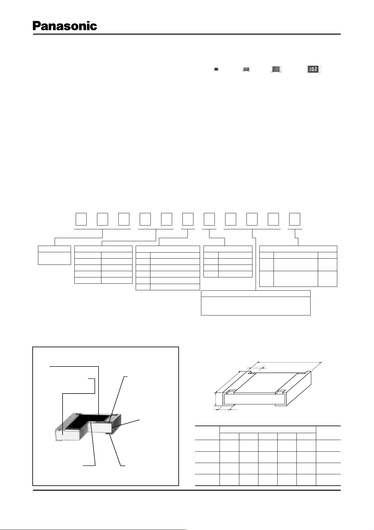
■ Explanation of Part Numbers
1
E
Product Code Size, Power Rating
Metal Film
Chip Resistors
Type: inches Power Rating
2A : 0402
3A : 0603
6A : 0805
8A : 1206
2
R
0.063 W
0.1 W
0.125 W
0.25 W
3
A
4
3
Temperature Coefficient
Code
R
P
E
H
K
A
±1010
±1510
±2510
±5010
±10010
5
T.C.R.
–6
/°C (ppm/°C)
–6
/°C (ppm/°C)
–6
/°C (ppm/°C)
–6
/°C (ppm/°C)
–6
/°C (ppm/°C)
6
E
7
B
Resistance Tolerance
Code
W
B
D
The first two digits are significant figures of resistance
and the third one denotes number of zeros following.
(ex.) 102:1k
8
1
Tolerance
±0.05 %
±0.1 %
±0.5 %
Resistance Value
9
0
Code
X
V
10
2
Packaging Methods
Punched Carrier
Taping (2 mm pitch)
Punched Carrier
Taping (4 mm pitch)
11
V
Packaging Type
ERA2A
ERA3A
ERA6A
ERA8A
■ Dimensions in mm (not to scale)■ Construction
Protective coating
Alumina substrate
High reliability
metal film
Design and specifi cations are each subject to change without notice. Ask factory for the current technical specifi cations before purchase and/or use.
Should a safety concern arise regarding this product, please be sure to contact us immediately.
Electrode (Inner)
Electrode
(Between)
Electrode (Outer)
Type
(inches)
ERA2A
(0402)
ERA3A
(0603)
ERA6A
(0805)
ERA8A
(1206 )
Dimensions (mm)
LWa b t
1.00
1.60
2.00
3.20
±0.10
±0.20
±0.20
±0.20
0.50
0.80
1.25
1.60
+0.10
–0.05
±0.20
±0.10
±0.10
0.15
0.30
0.40
0.50
±0.10
±0.20
±0.25
±0.25
0.25
0.30
0.40
0.50
±0.10
±0.20
±0.25
±0.25
0.35
0.45
0.50
0.60
Mass (Weight)
[g/1000 pcs.]
±0.05
±0.10
±0.10
±0.10
Mar. 2009
0.6
2
4
8
Metal Film Chip Resistors, High Reliability Type
■ Ratings
Power
Typ e
(inches)
Rating
at 85 °C
(W)
ERA2A
(0402)
ERA3A
(0603)
ERA6A
(0805)
ERA8A
(1206 )
(1) Rated Co ntinuous Working Voltage (RCWV) shall be de ter mined from RCWV=Rated Power Re sis tance Values, or Limiting Element Voltage
(max. RCWV) list ed above, whichever less.
(2) Overload (Short-time Overload) Test Voltage (SOTV) shall be de termined from SOTV=2.5 Power Rating or max. Over load Volt age list ed above
which ev er less.
(3) E96 series resistance values are also available. Please contact us for details.
0.063 25 50
0.1 75 150
0.125 100 200
0.25 150 300
Limiting Element
Voltage (Maximum
(1)
RCWV)
(V)
Maximum
Overload
Voltage
(V)
(2)
Typ e
(detail)
Resistance
Tol e rance
(%)
ERA2AKD ±0.5 ±100
ERA2AED ±0.5
ERA2AEB ±0.1
ERA3AHD ±0.5 ±50
ERA3AED ±0.5
ERA3AEB ±0.1
ERA6AHD ±0.5 ±50
ERA6AED ±0.5
ERA6AEB ±0.1
ERA6APB ±0.1 ±15
ERA6ARB ±0.1
ERA6ARW ±0.05
ERA8AHD ±0.5 ±50
ERA8AED ±0.5
ERA8AEB ±0.1
T.C.R .
–6
/°C
[10
(ppm/ °C)]
±25
±25
±25
±10
±25
Resistance
Range
(3)
()
10 to 43 (E24)
47 to 100 k (E24)
10 to 43 (E24)
47 to 330 k (E24)
10 to 43 (E24)
47 to 1 M (E24)
470 to 100 k (E24)
1 k to 100 k (E24)
10 to 43 (E24)
47 to 1 M (E24)
Category Temperature
Range (Operating
Temp e r ature R a n g e)
(°C)
–55 to +155
Power Derating Curve
For resistors operated in ambient temperatures above
85 °C, power rating shall be derated in ac cor dance
with the fi gure on the right.
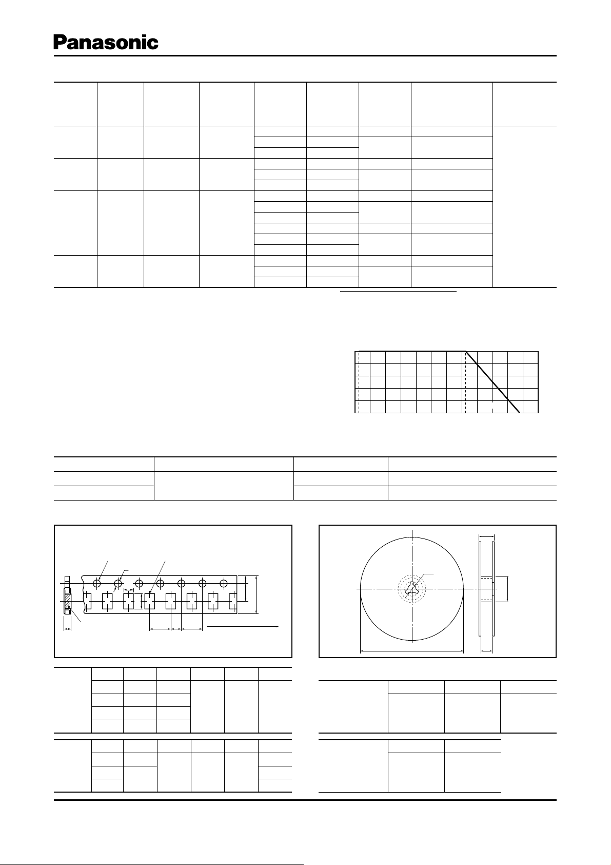
■ Packaging Methods (Taping)
● Standard Quantity
Typ e Kin d o f Taping Pi tch (P1)Quantity
ERA2A
ERA3A, 6A, 8A
Sprocket hole Compartment
φD
A
T
Punched Carrier Taping
0
B
P1P2P
0
FE
W
Tape running directionChip component
100
Rated Load (%)
–55 °C
80
60
40
20
–40 –20 0 20 40 60 80 100 120 140 1600180–60
Ambient Temperature (°C)
85 °C
2 mm 10000 pcs./reel
4 mm 5000 pcs./reel
● Taping Reel● Carrier Taping
φC
155 °C
T
φB
φA
Typ e A B W F E
0.67
1.10
1.65
2.00
2.00
4.00
P
±0.05
±0.10
±0.15
±0.15
1
±0.10
±0.10
Dimensions
(mm)
2A
3A
6A
8A
形式
Dimensions
(mm)
2A
3A
6A, 8A
Design and specifi cations are each subject to change without notice. Ask factory for the current technical specifi cations before purchase and/or use.
Should a safety concern arise regarding this product, please be sure to contact us immediately.
1.17
1.90
2.50
3.60
2.00
±0.05
±0.10
±0.20
±0.20
P
2
±0.05
8.00
4.00
±0.20
P
0
±0.10
3.50
1.50
±0.05
D
φ
0
+0.10
–0
1.75
0.52
0.70
0.84
±0.10
T
±0.05
±0.05
±0.05
Dimensions
(mm)
Dimensions
(mm)
φ
180.0
A
+0
–3.0
B
φ
60 min. 13.0
WT
9.0
±1.0
11.4
±1.0
W
C
φ
±1.0
Feb. 2009

Metal Film Chip Resistors, High Reliability Type
■ Recommended Land Pattern
In case of fl ow soldering, the land width must be small er than the Chip Resistor width to properly control the sol der amount
properly. Generally, the land width should be 0.7 to 0.8 times (W) of the width of chip resistor. In case of refl ow soldering,
solder amount can be adjusted, there fore the land width should be set to 1.0 to 1.3 times chip resistor width (W).
Chip Resistor
c
a
b
■ Recommended Soldering Conditions
Recommendations and precautions are described below.
Recommended soldering conditions for refl ow
●
· Refl ow soldering shall be performed a maximum of
two times.
· Please contact us for additional information when
used in conditions other than those specifi ed.
· Please measure the temperature of the terminals
and study every kind of solder and printed circuit
board for solderability be fore ac tu al use.
Peak
Typ e
(inches)
ERA2A(0402)
ERA3A(0603)
ERA6A(0805)
ERA8A(1206)
0.5 to 0.6 1.4 to 1.6 0.4 to 0.6
0.7 to 0.9 2 to 2.2 0.8 to 1
1 to 1.4 3.2 to 3.8 0.9 to 1.4
2 to 2.4 4.4 to 5.0 1.2 to 1.8
For soldering (Example : Sn/Pb)
Temp erature Time
Preheating 140 °C to 160 °C 60 s to 120 s
Main heating Above 200 °C 30 s to 40 s
Peak 235 ± 5 °C max. 10 s
Dimensions (mm)
abc
Preheating
Heating
Temperature
For lead-free soldering (Example : Sn/Ag/Cu)
Temp erature Time
Preheating 150 °C to 180 °C 60 s to 120 s
Main heating Above 230 °C 30 s to 40 s
Peak max. 260 °C max. 10 s
Time
Recommended soldering conditions for fl ow
●
For soldering For lead-free soldering
Temp erature TimeTemperatureTime
Preheating 140 °C to 180 °C 60 s to 120 s 150 °C to 180 °C 60 s to 120 s
Soldering 245 ± 5 °C 20 s to 30 s max. 260 °C max. 10 s
Safety Precautions
The following are precautions for individual products. Please also refer to the precautions common to Fixed Resistors
shown on page ER2 of this catalog.
1. Keep the rated power and ambient temperature within the specifi ed derating curve.
* When positioning and mounting Metal Film Chip Resistors (hereafter called the resistors), make allowance for the
effect of heat generated through close contact between the resistors and neigh bor ing components and for the
temperature rise of adjacent heat-generating components.
2. If a transient load (heavy load in a short time) like a pulse is expected to be applied, check and evaluate the operations
of the resistors when installed in your products before use.
When applying pulses to the resistors, keep the pulse peak within the rated voltage.
3. Do not use halogen-based or other high-activity fl ux. Otherwise, the residue may impair the resistors' per for mance
and/or reliability.
4. When soldering with a soldering iron, never touch the resistors' bodies with the tip of the soldering iron. When using a
soldering iron with a high temperature tip, fi nish soldering as quickly as possible (within three seconds at 350 °C max.).
5. As the amount of applied solder becomes larger, the mechanical stress applied to the resistors increases, causing
problems such as cracks and faulty characteristics. Avoid applying an excessive amount of solder.
6. When the resistors' protective coatings are chipped, fl awed, or removed, the characteristics of the resistors may be
impaired. Take special care not to apply mechanical shock during automatic mounting or cause damage during
handling of the boards with the resistors mounted.
7. D o n o t a p p ly shock to the resistors or pinch them with a hard tool (e.g. pliers and tweezers). Otherwise, the resistors'
protective coatings and bodies may be chipped, affecting their performance.
8. Avoid excessive bending of printed circuit boards in order to protect the resistors from abnormal stress.
9. Do not immerse the resistors in solvent for a long time. Before using solvent, carefully check the effects of im mer sion.
Design and specifi cations are each subject to change without notice. Ask factory for the current technical specifi cations before purchase and/or use.
Should a safety concern arise regarding this product, please be sure to contact us immediately.
Feb. 2009

Safety Precautions
(Common precautions for Fixed Resistors)
• When using our products, no matter what sort of equipment they might be used for, be sure to make a written
agreement on the specifi cations with us in advance. The design and specifi cations in this catalog are subject
to change without prior notice.
• Do not use the products beyond the specifi cations described in this catalog.
• This catalog explains the quality and performance of the products as individual components. Be fore use, check
and evaluate their operations when installed in your products.
• Install the following systems for a failsafe design to ensure safety if these products are to be used in equip ment
where a defect in these products may cause the loss of human life or other signifi cant damage, such as damage to
vehicles (au to mo bile, train, vessel), traffi c lights, medical equipment, aerospace equipment, elec tric heating
ap pli anc es, com bus tion/gas equipment, rotating equipment, and disaster/crime prevention equip ment.
Systems equipped with a protection circuit and a protection device
✽
Systems equipped with a redundant circuit or other system to prevent an unsafe status in the event of a single fault
✽
(1) Precautions for use
• These products are designed and manufactured for general and stan dard use in general elec tron ic
equipment (e.g. AV equipment, home electric ap pli anc es, offi ce equipment, information and com mu ni ca tion
equipment)
• These products are not intended for use in the following special conditions. Be fore using the products, care ful ly
check the effects on their quality and performance, and determine whether or not they can be used.
1. In liquid, such as water, oil, chemicals, or organic solvent
2. In direct sunlight, outdoors, or in dust
3. In salty air or air with a high concentration of corrosive gas, such as Cl
4. Electric Static Discharge (ESD) Environment
These components are sensitive to static electricity and can be damaged under static shock (ESD).
Please take measures to avoid any of these environments.
Smaller components are more sensitive to ESD environment.
5. Electromagnetic Environment
Avoid any environment where strong electromagnetic waves exist.
6. In an environment where these products cause dew condensation
7. S e al i ng o r c o ating of these products or a printed circuit board on which these products are mounted, with resin
or other materials
• These products generate Joule heat when energized. Carefully position these products so that their heat will not
affect the other components.
• Carefully position these products so that their temperatures will not exceed the category temperature range due
to the effects of neighboring heat- generating com po nents. Do not mount or place heat- generating com po nents or
infl ammables, such as vinyl-coated wires, near these products .
• Note that non -cleaning solder, halogen-based highly active fl ux, or water-soluble fl ux may deteriorate the
performance or reliability of the products.
• Carefull y select a fl ux cleaning agent for use after soldering. An unsuitable agent may deteriorate the
performance or reliability. In particular, when using water or a water-soluble cleaning agent, be careful not to leave
water res i dues. Otherwise, the insulation performance may be deteriorated.
, H2S, NH3, SO2, or NO
2
2
(2) Precautions for storage
The performance of these products, including the solderability, is guaranteed for a year from the date of arrival at your
company, provided that they remain packed as they were when delivered and stored at a temperature of 5 °C to 35 °
C and a relative humidity of 45 % to 85 %.
Even within the above guarantee periods, do not store these products in the fol low ing conditions. Otherwise, their
elec tri cal performance and/or solderability may be deteriorated, and the packaging materials (e.g. tap ing ma te ri als)
may be de formed or deteriorated, resulting in mounting failures.
1. In salty air or in air with a high concentration of corrosive gas, such as Cl
, H2S, NH3, SO2, or NO
2
2
2. In direct sunlight
<Package markings>
Package markings include the product number, quantity, and country of origin.
In principle, the country of origin should be indicated in English.
Oct. 2007
– ER3 –
 Loading...