

Page 1
RoHS Directive compatibility information
http://www.mew.co.jp/ac/e/environment/
100A 100V DC
HIGH VOLTAGE RELAY
FEATURES
1. Compact and high capacity using
double contacts in series and
permanent magnet installed.
1) Nominal switching capacity (resistive
load): 100A 100V DC, Min. 10
2) Max. cut-off current: 800A 100V DC
2. Compact and lightweight for space
savings.
70mm (L) × 80mm (W) × 34mm (H)
2.756inch (L) × 3.150inch (W) ×
1.339inch (H)
3. Environmentally friendly
In consideration of the environment,
cadmium-free contacts, lead-free solder
are used.
4
EJ (AEJ)
EJ RELAYS (AEJ)
TYPICAL APPLICATIONS
Quick recharging power supplies for
AGVs (automatic guided vehicle), UPS
(uninterruptible power supplies), Fuel
cell, Combined heat/power generation
system, etc.
ORDERING INFORMATION
AEJ
EJ Relay
Contact arrangement
1: 1 Form A
Contact capacity
1: 100 A (100 V)
Operating function
0: Single side stable
Coil voltage (DC)
12: 12, 24: 24
TYPES
Contact arrangement Coil voltage Protective construction Terminal shape Part No.
1 Form A
Standard packing: Carton: 1 pc.; Case: 20 pcs.
12V DC
24V DC AEJ11024
Dust cover Screw terminal
RATING
1. Coil data
Nominal coil
voltage
12V DC Max. 9.0V DC Min. 1.0V DC 417mA 28.8Ω 5.0W
24V DC Max. 18.0V DC Min. 2.0V DC 208mA 115Ω 5.0W
Pick-up voltage
(at 20°C 68°F)
(Initial)
Drop-out voltage
(at 20°C 68°F)
(Initial)
Nominal coil current
[±10%] (at 20°C 68°F)
Coil resistance
[±10%] (at 20°C 68°F)
Nominal operating
power
(at 20°C 68°F)
AEJ11012
Max. allowable voltage
(at 20°C 68°F)
150%V of
nominal voltage
All Rights Reserved © COPYRIGHT Matsushita Electric Works, Ltd.
Page 2
EJ (AEJ)
2. Specifications
Characteristics Item Specifications
Arrangement 1 Form A
Contact voltage drop (Initial) Max. 0.15V (at 100A)
Contact material AgCuO type
Rating
Electrical
characteristics
Mechanical
characteristics
Expected life
Conditions Conditions for operation, transport and storage*
Unit weight Approx. 300g 10.58oz
Notes: *1 This value can change due to the switching frequency, environmental conditions and desired reliability level, therefore it is recommended to check this with the
*2 The upper operation ambient temperature limit is the maximum temperature that can satisfy the coil temperature rise value.
*3 Condition: Nominal switching 100cycles, each cut off 800A
*4 When using a surge absorbing element for the relay coil drive circuit, please use with a surge absorbing element with a clamp voltage of 1.5 to 2.0 times the rated
Nominal switching capacity (resistive load) 100A 100V DC
Max. carrying current/short time carrying current 1,000A (0.1s)
Min. switching capacity (Reference value)*
Max. cut-off current 800A 100V DC/3 cycle*
1
1A 12V DC
3
Overload opening rating 300A 150V DC/10 cycle
Insulation resistance (Initial)
Breakdown voltage
(Initial)
Between open contacts 1,500 Vrms for 1min. (Detection current: 10mA.)
Between contact and coil 2,500 Vrms for 1min. (Detection current: 10mA.)
Min. 100MΩ (at 500V DC)
Measurement at same location as “Initial breakdown voltage” section.
Operate time (at 20°C 68°F) Max. 30ms (Nominal voltage applied to the coil, excluding contact bounce time)
Release time (at 20°C 68°F) Max. 15ms (Nominal voltage applied to the coil)
2
Shock resistance
Functional
Destructive
Min. 500 m/s
Min. 50 m/s
Min. 1000 m/s2 (Nominal voltage applied to the coil or deenergized.)
(Half-wave pulse of sine wave: 6 ms)
Functional 10 to 200Hz, 44.1m/s
Vibration resistance
Destructive
10 to 200Hz, 44.1m/s2 (Nominal voltage applied to the coil or deenergized)
(Time of vibration for each direction; X, Y, Z direction: 4 hours)
Mechanical Min. 10
Electrical
Min. 10
(Resistive load, operating frequency 1s ON, 9s OFF, room temperature)
2
Ambient temperature: –40°C to +85°C –40°F to +185°F
(Nominal voltage applied to the coil)
2
(deenergized) (Half-wave pulse of sine wave: 11 ms; detection time: 10µs.)
2
(Nominal voltage applied to the coil or deenergized)
6
4
(at 100A 100V DC)
actual load.
Refer to 6. Conditions for operation, transport and storage mentioned in AMBIENT ENVIRONMENT .
operating voltage. When the coil is connected in parallel with a diode, resistor or capacitor, the release time will delay which might lead to degradation in shutoff
performance and electrical life.Contact terminals have polarity; therefore, please obey the wiring diagram when connecting contacts.The electrical load
performance value applies when a varistor is connected in parallel with the coil.
REFERENCE DATA
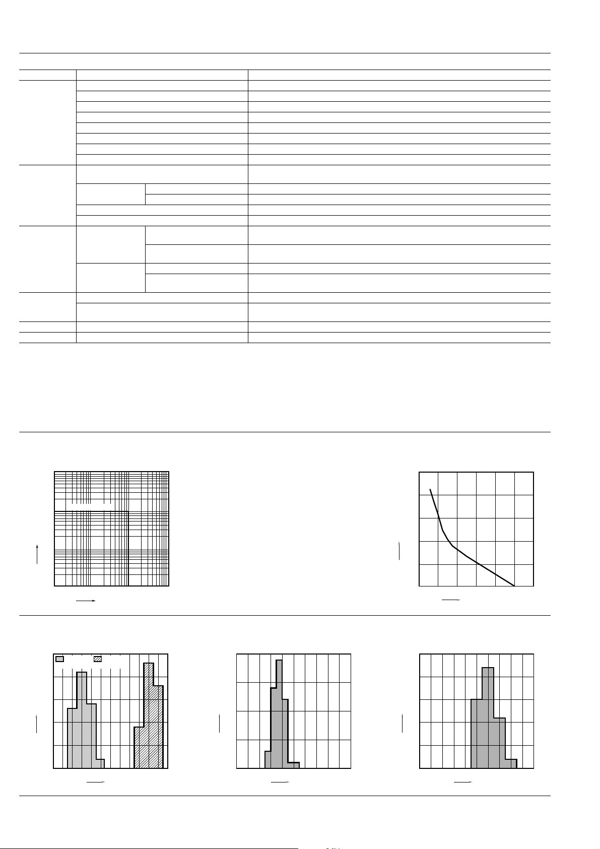
1. Maximum value for switching capacity 2. Carrying current limit
1,000
DC resistive load
100
Contact current, A
10
10 100 1,000
Contact voltage, V
3. Distribution of pick-up and drop-out voltages
Tested sample: AEJ11012, 50 pcs.
25
20
15
Quantity
10
Drop-out
voltage
Pick-up
voltage
)(20°C 68°F
Connection electric wire: 40mm
Ambient temperature: 85°C 185°F
Standard for judgment: Relay contacts off when
carrying finished.
4. Distribution of operate time
Tested sample: AEJ11012, 50 pcs.
20
15
Quantity
10
2
Carrying current and carrying time
10000
1000
100
Carrying time, s
10
1
0.1
0 200 400 600 800 1000 1200
Carrying current, A
5. Distribution of release time
Tested sample: AEJ11012, 50 pcs.
)(20°C 68°F
25
20
15
Quantity
10
)(20°C 68°F
5
0
3.02.01.51.0 2.5 3.5 4.5 5.04.0 5.5 6.0 7.06.5
Voltage, V
5
0
13.011.010.0 12.0 14.0 16.0 17.015.0 18.0 19.0 20.0
Time, ms
5
0
1.50.50.0 1.0 2.0 3.0 3.52.5 4.0 4.5 5.0
Time, ms
All Rights Reserved © COPYRIGHT Matsushita Electric Works, Ltd.
Page 3

6. Functional shock resistance
Tested sample: AEJ11012, 3 pcs.
Half-wave pulse of sine wave: 11 ms
Detection time: 10µs.
Applied direction: 6 directions
Applied cycle: Each of 3 cycles
Deenengized condition
Energized condition
Z'
Y
2
1,000m/s
Z
Y'
X
Y
X'
XZ
2
1,000m/s
1,000m/s
2
EJ (AEJ)
1,000m/s
DIMENSIONS (Unit: mm inch)
External dimensions
71.4
2.811
58.4
2.299
36.0
1.417
70.0
2.756
31.5
1.240
3.7
.146
(–) (+)
2
Z' X'
1,000m/s
Y'
3.7
.146
2-M6
2-M.236
2-5.3 dia.
2-.209 dia.
1,000m/s
2
+0.3
−0.1
+.012
−.004
2
1.323
33.6
+1.0
−0.5
+.039
−.020
Schematic (Top view)
2 (–)
1 (+)
Coil terminal
Coil terminal
Mounting hole pattern (Top view)
66.0
2.598
2-5.3
2-.209
Tolerance: ±0.1 ±.004
37.5
15.0
.591
1.476
27.0
1.063
<>
52.0
2.047
66.0±0.3
2.598±.012
80.0
3.150
10.0
.394
300±20
11.811±.787
34.0
1.339
+1.0
−0.5
+.039
−.020
Notes: 1. Please be warned that contact terminals have polarity. There is no polarity in the coil input line.
2. We will make separate consideration if a coil lead wire connector is desired.
Tolerance:
Max. 10mm .394inch: ±0.3 ±.012
10 to 50mm .394 to 1.969inch:±0.6 ±.024
Min. 50mm 1.969inch: ±1.0 ±.039
All Rights Reserved © COPYRIGHT Matsushita Electric Works, Ltd.
Page 4

EJ (AEJ)
;;
;;
;;
;;
;;
;;
;;
;;
;
;
;
;;
Tolerance range
(Avoid
condensation when
used at temperatures
higher than 0°C 32°F)
(Avoid freezing when
used at temperatures
lower than 0°C 32°F)
85
5
–40
–40
0
+32
+85
+185
Temperature, °C °F
Humidity, %R.H.
NOTES
1. To ensure proper operation, the
voltage applied to the coil should be
the rated operating voltage of the coil.
Also, be aware that the pick-up and
drop-out voltages will fluctuate
depending on the ambient
temperature and operating conditions.
2. Heat, smoke, and even a fire may
occur if the relay is used in conditions
outside of the allowable ranges for the
coil ratings, contact ratings, operating
cycle lifetime, and other
specifications. Therefore, do not use
the relay if these ratings are exceeded.
3. If the relay has been dropped, the
appearance and characteristics
should always be checked before use.
4. This relay is for DC loads. Do not
use it for AC load switching.
5. Make sure that the relay is wired
correctly. Incorrect wiring may cause
unexpected events or the generation
of heat or flames.
6. We recommend you use a surge
absorbing element with a clamp
voltage of 1.5 to 2.0 times the rated
operating voltage for the relay coil
drive circuit as a means for relay coil
surge absorption. Please avoid the
use of diodes, capacitors and
resistors because they lead to
degradation in cut-off performance.
7. Avoid mounting the relay in strong
magnetic fields (near a transformer or
magnet) or close to an object that
radiates heat.
8. Electrical life
This relay is a high-voltage direct-current
switch. In its final breakdown mode, it
may lose the ability to provide the proper
cut-off. Therefore, do not exceed the
indicated switching capacity and life.
(Please treat the relay as a product with
limited life and replace it when
necessary.)
In the event that the relay loses cut-off
ability, there is a possibility that burning
may spread to surrounding parts, so
configure the layout so that the power is
turned off within one second.
9. If the power is turned off and then
immediately on after applying the
rated voltage (current) continuously to
the relay’s coil and contact, the
resistance of the coil will increase due
to a rise in the coil temperature. This
causes the pick-up voltage to rise, and
possibly exceed the rated pick-up
voltage. In these circumstances, take
measures such as reducing the load
current, limiting the duration of
current flow, and applying a coil
voltage higher than the rated
operating voltage (quick start).
10. If you are using an inductive load
(L load) such that L/R > 1 ms, add
surge protection in parallel with the
inductive load. If this is not done, the
electrical life will decrease and cut-off
failure may occur.
11. Be careful that foreign matter and
oils and fats kind doesn’t stick to the
main terminal part because it is likely
to cause a terminal part to give off
unusual heat.
12. Avoid excessive load applied to
the terminal in case of installing such
as a bus bar etc., because it might
give bad influence to the opening and
closing performance.
Tighten each of the screws within the
rated ranges given below.
Main terminal (M6 screw):
6.0N·m to 8.0N·m
Main unit mounting (M5 screw):
2.5N·m to 3.6N·m
13. Usage, transport and storage
conditions
Ambient temperature, humidity, and
atmospheric pressure during usage,
transport, and storage of the relay:
1) Temperature: –40 to +85°C –40 to
+185°F
2) Humidity: 5 to 85% RH
(Avoid freezing and condensation.)
3) Atmospheric pressure: 85 to 106 kPa
Temperature and humidity range for
usage, transport, and storage:
;;;
;;
;
;
;
;;
;;;
;;
;;;;;;
;;;;;;;
;
;;;;;;;;
;;;;
;
;;;;;;
;;
4) Condensation
Condensation forms when there is a
sudden change in temperature under
high temperature and high humidity
conditions. Condensation will cause
deterioration of the relay insulation.
5) Freezing
Condensation or other moisture may
freeze on the relay when the
temperatures is lower than 0°C 32°F.
This causes problems such as sticking of
movable parts or operational time lags.
6) Low temperature, low humidity
environments
The plastic becomes brittle if the relay is
exposed to a low temperature, low
humidity environment for long periods of
time.
For Cautions for Use, see Relay Technical Information.
All Rights Reserved © COPYRIGHT Matsushita Electric Works, Ltd.
 Loading...