

Page 1
Order No: PAPAMY1501049CE
/
MP
O
S
O
123
C
/
TEM P
O
TIMER
S
O
2
3
CHEC
K
FAN
AUTO
SPEED
HEAT
COOL
DRY
FAN
OFF/ON
FF/ON
ECONAVI
MODE
TEMP
TE
POWERFUL/
FANSPEED
QUIET
TIMER
TIMER
ON
123
FF
SETCHECK CLOCK RESET
HECK
AIR
SWING
AUTO
COMFORT
AIRSWING
ET
SET
CANCEL
CANCELONOFF
AC RC
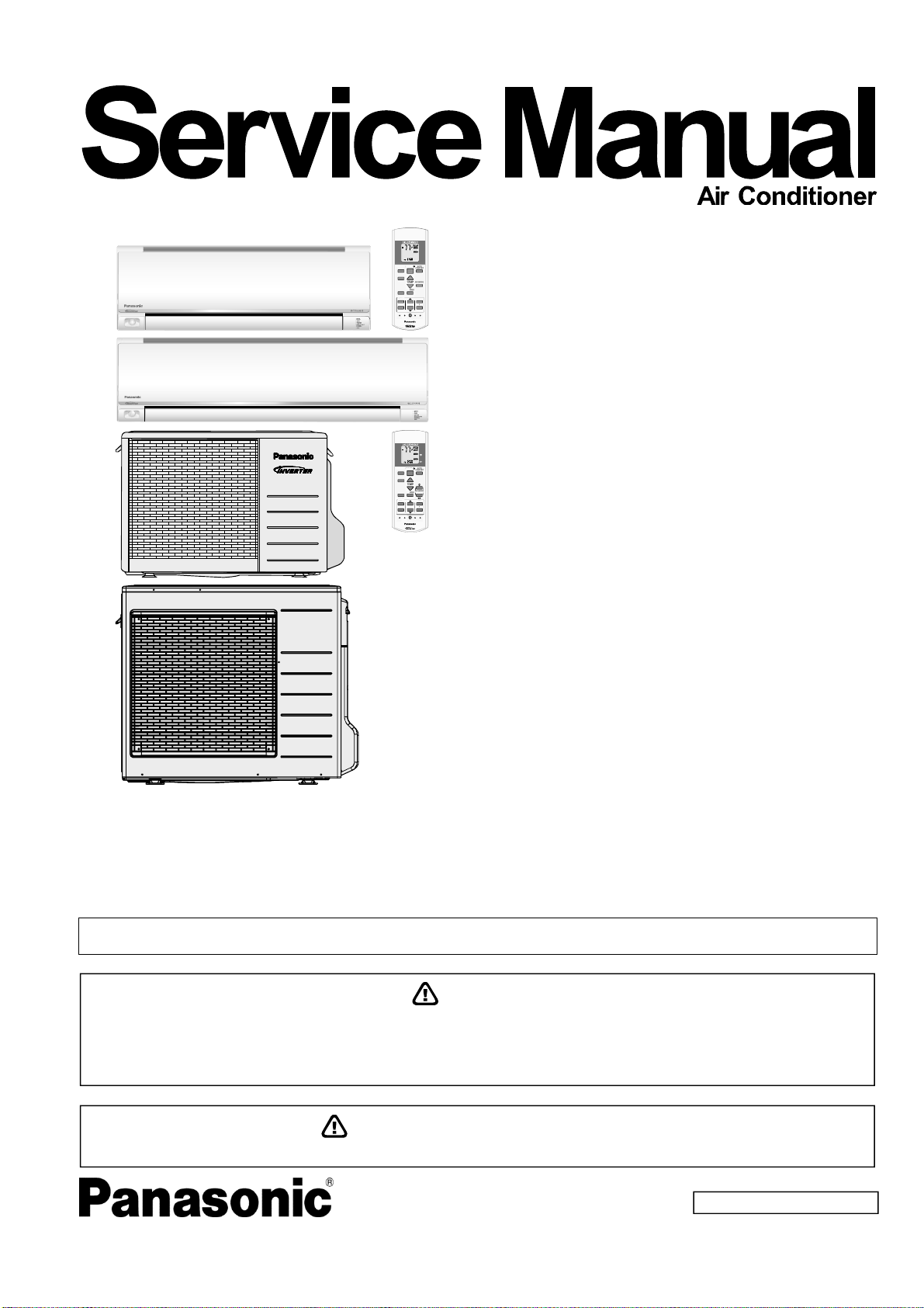
CS-E12RKUAW
CS-E18RKUAW
Indoor Unit Outdoor Unit
CS-E9RKUAW
CU-E9RKUA
CU-E12RKUA
CU-E18RKUA
AUTO
HEAT
COOL
DRY
FAN
ECONAVI
MODE
POWERFUL/
QUIET
TIMER
ON
1
123
FF
SETCHECK CLOCK RESET
CS-E24RKUAW
CU-E24RKUA
FAN
SPEED
AIR
SWING
AUTO
OFF/ON
FF/ON
COMFORT
TEMP
AIRSWING
FANSPEED
ET
SET
CANCEL
CANCELONOFF
AC RC
Destination
USA
Canada
Please file and use this manual together with the service manual for Model No. CU-2E18NBU and CU-5E36QBU, Order No.
PHAAM1111120A1 and PAPAMY1312037CE.
WARNING
This service information is designed for experienced repair technicians only and is not designed for use by the general public.
It does not contain warnings or cautions to advise non-technical individuals of potential dangers in attempting to service a product.
Products powered by electricity should be serviced or repaired only by experienced professional technicians. Any attempt to
service or repair the products dealt with in this service information by anyone else could result in serious injury or death.
In order to avoid frostbite, be assured of no refrigerant leakage during the installation or repairing of refrigerant circuit.
PRECAUTION OF LOW TEMPERATURE
© Panasonic Corporation 2015.
Page 2

TABLE OF CONTENTS
1. Safety Precautions ............................................. 3
2. Specification ....................................................... 5
3. Features ............................................................. 11
4. Location of Controls and Components .......... 12
4.1 Indoor Unit .................................................. 12
4.2 Outdoor Unit ............................................... 12
4.3 Remote Control .......................................... 12
5. Dimensions ....................................................... 13
5.1 Indoor Unit .................................................. 13
5.2 Outdoor Unit ............................................... 15
6. Refrigeration Cycle Diagram ........................... 16
6.1 CU-E9RKUA CU-E12RKUA ...................... 16
6.2 CU-E18RKUA CU-E24RKUA .................... 17
7. Block Diagram .................................................. 18
7.1 CS-E9RKUAW CU-E9RKUA
CS-E12RKUAW CU-E12RKUA ................. 18
7.2 CS-E18RKUAW CU-E18RKUA
CS-E24RKUAW CU-E24RKUA ................. 19
8. Wiring Connection Diagram ............................ 20
8.1 Indoor Unit .................................................. 20
8.2 Outdoor Unit ............................................... 22
9. Electronic Circuit Diagram .............................. 24
9.1 Indoor Unit .................................................. 24
9.2 Outdoor Unit ............................................... 26
10. Printed Circuit Board ....................................... 28
10.1 Indoor Unit .................................................. 28
10.2 Outdoor Unit ............................................... 30
11. Installation Instruction (E9RK and E12RK) .... 33
11.1 Select the Best Location ............................. 33
11.2 Indoor Unit .................................................. 34
11.3 Outdoor Unit ............................................... 38
12. Installation Instruction
(E18RK and E24RK) ......................................... 41
12.1 Select the Best Location ............................. 41
12.2 Indoor Unit .................................................. 42
12.3 Outdoor Unit ............................................... 46
13. Operation Control ............................................. 49
13.1 Basic Function ............................................ 49
13.2 Indoor Fan Speed Control .......................... 50
13.3 Indoor Fan Motor Operation ....................... 51
13.4 Outdoor Fan Motor Operation .................... 51
13.5 Airflow Direction .......................................... 52
13.6 Quiet Operation (Cooling Mode/Cooling
Area of Dry Mode) ...................................... 53
13.7 Quiet Operation (Heating) .......................... 54
13.8 Powerful Mode Operation ........................... 54
13.9 Timer Control .............................................. 54
13.10 Auto Restart Control ................................... 55
13.11 Indication Panel .......................................... 55
13.12 ECONAVI and AUTO COMFORT
Operation ....................................................55
14. Operation Control
(For Multi Split Connection) ............................59
14.1 Cooling operation .......................................59
14.2 Soft Dry Operation ......................................59
14.3 Heating Operation ......................................59
14.4 Automatic Operation
(For Multi Split Connection Only) ...............60
14.5 Indoor Fan Motor Operation .......................60
14.6 Powerful Mode Operation ...........................60
14.7 Auto restart control .....................................60
14.8 Indication Panel ..........................................60
15. Protection Control (E9RK and E12RK) ...........61
15.1 Protection Control For All Operations .........61
15.2 Protection Control For Cooling & Soft Dry
Operation ....................................................63
16. Protection Control (E18RK and E24RK) .........66
16.1 Protection Control For All Operations .........66
16.2 Protection Control For Cooling & Soft Dry
Operation ....................................................67
17. Servicing Mode .................................................70
17.1 Auto Off/On Button .....................................70
17.2 Cooling Only Operation
(Single connection Only, Multi connection
please refer to Multi outdoor manual) .........71
17.3 Remote Control Button ...............................72
18. Troubleshooting Guide ....................................73
18.1 Refrigeration Cycle System ........................73
18.2 Breakdown Self Diagnosis Function ...........75
18.3 Error Code Table ........................................76
18.4 Self-diagnosis Method ................................78
19. Disassembly and Assembly Instructions ... 107
19.1 CS-E9RKUAW CS-E12RKUAW ............ 107
19.2 CS-E18RKUAW CS-E24RKUAW .......... 111
19.3 Outdoor Electronic Controller Removal
Procedure ................................................ 114
20. Technical Data ............................................... 116
20.1 Cool Mode Performance Data ................. 116
20.2 Heat Mode Performance Data ................. 120
21. Service Data ................................................... 122
21.1 Cool Mode Outdoor Air Temperature
Characteristic ........................................... 122
21.2 Heat Mode Outdoor Air Temperature
Characteristic ........................................... 126
21.3 Piping Length Correction Factor .............. 130
22. Exploded View and Replacement Parts
List .................................................................. 132
22.1 Indoor Unit ............................................... 132
22.2 Outdoor Unit ............................................ 138
2
Page 3
1. Safety Precautions
Read the following “SAFETY PRECAUTIONS” carefully before perform any servicing.
Electrical work must be installed or serviced by a licensed electrician. Be sure to use the correct rating of the
power plug and main circuit for the model installed.
The caution items stated here must be followed because these important contents are related to safety. The
meaning of each indication used is as below. Incorrect installation or servicing due to ignoring of the instruction
will cause harm or damage, and the seriousness is classified by the following indications.
WARNING
CAUTION
The items to be followed are classified by the symbols:
Carry out test run to confirm that no abnormality occurs after the servicing. Then, explain to user the operation,
care and maintenance as stated in instructions. Please remind the customer to keep the operating instructions for
future reference.
1. Do not modify the machine, part, material during repairing service.
This indication shows the possibility of causing death or serious injury
This indication shows the possibility of causing injury or damage to properties.
This symbol denotes item that is PROHIBITED from doing.
WARNING
2. If wiring unit is supplied as repairing part, do not repair or connect the wire even only partial wire break. Exchange the whole wiring unit.
3. Do not wrench the fasten terminal. Pull it out or insert it straightly.
4. Engage authorized dealer or specialist for installation and servicing. If installation of servicing done by the user is defective, it will cause water
leakage, electrical shock or fire.
5. Install according to this installation instructions strictly. If installation is defective, it will cause water leakage, electric shock or fire.
6. Use the attached accessories parts and specified parts for installation and servicing. Otherwise, it will cause the set to fall, water leakage, fire
or electrical shock.
7. Install at a strong and firm location which is able to withstand the set’s weight. If the strength is not enough or installation is not properly done,
the set will drop and cause injury.
8. For electrical work, follow the local national wiring standard, regulation and the installation instruction. An independent circuit and single outlet
must be used. If electrical circuit capacity is not enough or defect found in electrical work, it will cause electrical shock or fire.
9. This equipment is strongly recommended to be installed with Earth Leakage Circuit Breaker (ELCB) or Residual Current Device (RCD).
Otherwise, it may cause electrical shock and fire in case equipment breakdown or insulation breakdown.
10. Do not use joint cable for indoor/outdoor connection cable. Use the specified indoor/outdoor connection cable, refer to installation instruction
CONNECT THE CABLE TO THE INDOOR UNIT and connect tightly for indoor/outdoor connection. Clamp the cable so that no external force
will be acted on the terminal. If connecting or fixing is not perfect, it will cause heat up or fire at the connection.
11. Wire routing must be properly arranged so that control board cover is fixed properly. If control board cover is not fixed perfectly, it will cause
heat-up or fire at the connection point of terminal, fire or electrical shock.
12. When install or relocate air conditioner, do not let any substance other than the specified refrigerant, eg. air etc. mix into refrigeration cycle
(piping). (Mixing of air etc. will cause abnormal high pressure in refrigeration cycle and result in explosion, injury etc.).
13. Do not install outdoor unit near handrail of veranda. When installing air-conditioner unit at veranda of high rise building, child may
climb up to outdoor unit and cross over the handrail and causing accident.
14. This equipment must be properly earthed. Earth line must not be connected to gas pipe, water pipe, earth of lightning rod and
telephone. Otherwise, it may cause electrical shock in case equipment breakdown or insulation breakdown.
15. Keep away from small children, the thin film may cling to nose and mouth and prevent breathing.
16. Do not use unspecified cord, modified cord, joint cord or extension cord for power supply cord. Do not share the single outlet with
other electrical appliances. Poor contact, poor insulation or over current will cause electrical shock or fire.
17. Tighten the flare nut with torque wrench according to specified method. If the flare nut is over-tightened, after a long period, the flare may
break and cause refrigerant gas leakage.
18. For R410A model, use piping, flare nut and tools which is specified for R410A refrigerant. Using of existing (R22) piping, flare nut
and tools may cause abnormally high pressure in the refrigerant cycle (piping), and possibly result in explosion and injury.
Thickness or copper pipes used with R410A must be more than 1/32" (0.8 mm). Never use copper pipes thinner than 1/32" (0.8 mm).
It is desirable that the amount of residual oil is less than 0.0008 oz/ft (40 mg/10 m).
3
Page 4
19. During installation, install the refrigerant piping properly before run the compressor. (Operation of compressor without fixing refrigeration piping
and valves at opened condition will cause suck-in of air, abnormal high pressure in refrigeration cycle and result in explosion, injury etc.).
20. During pump down operation, stop the compressor before remove the refrigeration piping. (Removal of refrigeration piping while compressor is
operating and valves are opened condition will cause suck-in of air, abnormal high pressure in refrigeration cycle and result in explosion, injury
etc.).
21. After completion of installation or service, confirm there is no leakage of refrigerant gas. It may generate toxic gas when the refrigerant
contacts with fire.
22. Ventilate if there is refrigerant gas leakage during operation. It may cause toxic gas when the refrigerant contacts with fire.
23. Do not insert your fingers or other objects into the unit, high speed rotating fan may cause injury.
24. Must not use other parts except original parts describe in catalog and manual.
25. Using of refrigerant other than the specified type may cause product damage, burst and injury etc.
1. Do not install the unit at place where leakage of flammable gas may occur. In case gas leaks and accumulates at surrounding of the
unit, it may cause fire.
2. Carry out drainage piping as mentioned in installation instructions. If drainage is not perfect, water may enter the room and damage
the furniture.
3. Tighten the flare nut with torque wrench according to specified method. If the flare nut is over-tightened, after a long period, the flare
may break and cause refrigerant gas leakage.
4. Do not touch outdoor unit air inlet and aluminium fin. It may cause injury.
WARNING
CAUTION
5. Select an installation location which is easy for maintenance.
6. Pb free solder has a higher melting point than standard solder; typically the melting point is 50°F – 70°F (30°C – 40°C) higher. Please use
a high temperature solder iron. In case of the soldering iron with temperature control, please set it to 700 ± 20°F (370 ± 10°C).
Pb free solder will tend to splash when heated too high (about 1100°F / 600°C).
7. Power supply connection to the room air conditioner.
Power supply cord shall be UL listed or CSA approved 3 conductor with minimum AWG14 (For E9RK and E12RK) and AWG12
(For E18RK and E24RK) wires.
Power supply point should be in an easily accessible place for power disconnection in case of emergency.
In some countries, permanent connection of this air conditioner to the power supply is prohibited.
Fix power supply connection to a circuit breaker for permanent connection.
Use NRTL approved fuse or circuit breaker (rating refers to name plate) for permanent connection.
8. Do not release refrigerant during piping work for installation, servicing, reinstallation and during repairing a refrigerant parts. Take
care of the liquid refrigerant, it may cause frostbite.
9. Installation or servicing work: It may need two people to carry out the installation or servicing work.
10. Do not install this appliance in a laundry room or other location where water may drip from the ceiling, etc.
11. Do not sit or step on the unit, you may fall down accidentally.
12. Do not touch the sharp aluminium fins or edges of metal parts.
If you are required to handle sharp parts during installation or servicing, please wear hand glove.
Sharp parts may cause injury.
4
Page 5
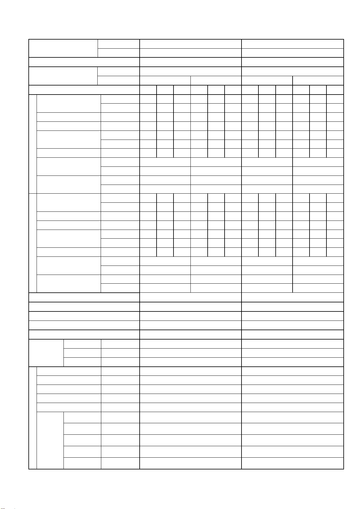
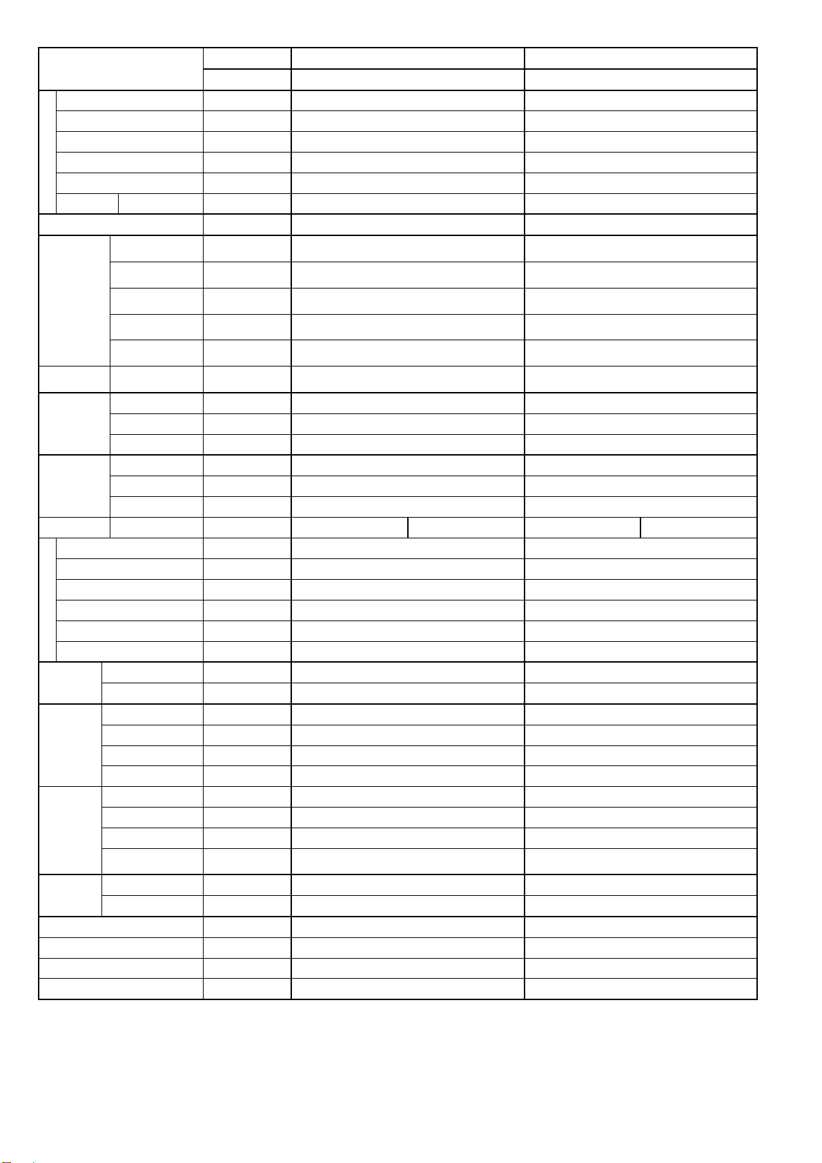
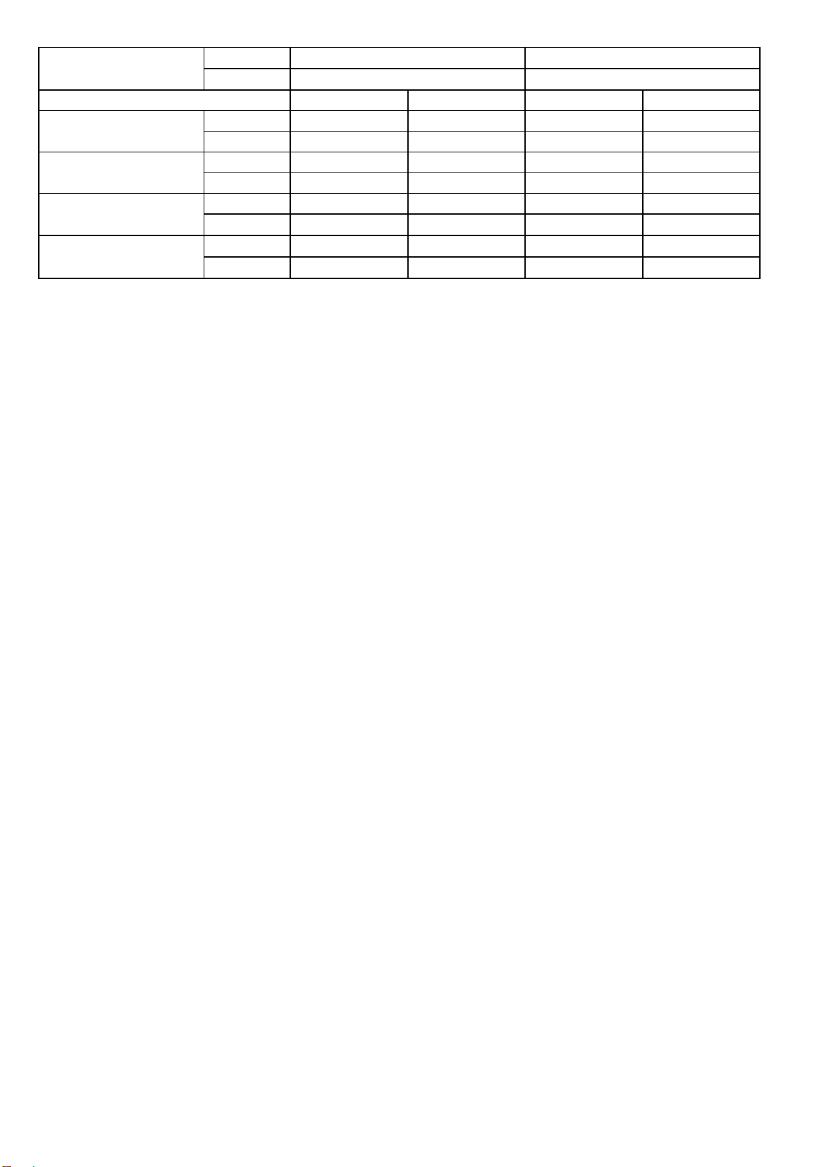
2. Specification
Model
Performance Test Condition ARI ARI
Power Supply
Min. Mid. Max. Min. Mid. Max. Min. Mid. Max. Min. Mid. Max.
Capacity
Running Current A - 3.6 - - 3.2 - - 4.7 - - 4.2 -
Input Power W 250 690 850 250 690 850 250 920 1.15k 250 920 1.15k
EER
Cooling
Heating
Compressor
Indoor Fan
Power Factor % - 92 - - 94 - - 94 - - 95 -
Indoor Noise (H / L / QLo)
Outdoor Noise (H / L / QLo)
Capacity
Running Current A - 5.7 - - 5.1 - - 6.3 - - 5.6 -
Input Power W 200 1.12k 1.50k 200 1.12k 1.50k 200 1.25k 1.71k 200 1.25k 1.71k
COP
Power Factor % - 94 - - 95 - - 95 - - 97 -
Indoor Noise (H / L / QLo)
Outdoor Noise (H / L / QLo)
Max Current (A) / Max Input Power (W) 7.0 / 1.57k 7.8 / 1.71k
Starting Current (A) 5.7 6.3
Min Circuit Ampacity 15.0 15.0
Max. Current Protection 15.0 15.0
SEER / HSPF 23.00 / 11.00 22.50 / 11.00
Type Hermetic Motor / Rotary Hermetic Motor / Rotary
Motor Type Brushless (4 poles) Brushless (4 poles)
Output Power W 700 700
Type Cross-flow fan Cross-flow fan
Material ASG20K1 ASG20K1
Motor Type DC (8 poles) DC (8 poles)
Input Power W 47.0 - 47.0 47.0 - 47.0
Output Power W 40 40
QLo rpm
Lo rpm
Speed
Me rpm
Hi rpm
SHi rpm
Indoor CS-E9RKUAW CS-E12RKUAW
Outdoor CU-E9RKUA CU-E12RKUA
Phase, Hz Single, 60 Single, 60
V 208 230 208 230
kW 1.20 2.64 3.00 1.20 2.64 3.00 1.20 3.36 3.90 1.20 3.36 3.90
BTU/h 4100 9000 10200 4100 9000 10200 4100 11500 13300 4100 11500 13300
W/W 4.80 3.83 3.53 4.80 3.83 3.53 4.80 3.65 3.39 4.80 3.65 3.39
Btu/hW 16.40 13.00 12.00 16.40 13.00 12.00 16.40 12.50 11.55 16.40 12.50 11.55
dB-A 40 / 25 / 20 40 / 25 / 20 43 / 28 / 20 43 / 28 / 20
Power Level dB 56 / - / - 56 / - / - 59 / - / - 59 / - / -
dB-A 47 / - / - 47 / - / - 48 / - / - 48 / - / -
Power Level dB 62 / - / - 62 / - / - 63 / - / - 63 / - / -
kW 1.20 3.52 4.14 1.20 3.52 4.14 1.20 4.05 4.77 1.20 4.05 4.77
BTU/h 4100 12000 14100 4100 12000 14100 4100 13800 16300 4100 13800 16300
W/W 6.00 3.14 2.76 6.00 3.14 2.76 6.00 3.24 2.79 6.00 3.24 2.79
Btu/hW 20.50 10.70 9.40 20.50 10.70 9.40 20.50 11.00 9.50 20.50 11.00 9.50
dB-A 42 / 29 / 26 42 / 29 / 26 44 / 35 / 32 44 / 35 / 32
Power Level dB 58 / - / - 58 / - / - 60 / - / - 60 / - / -
dB-A 48 / - / - 48 / - / - 49 / - / - 49 / - / -
Power Level dB 63 / - / - 63 / - / - 64 / - / - 64 / - / -
Cooling : 610
Heating : 730
Cooling : 710
Heating : 830
Cooling : 910
Heating : 1040
Cooling : 1120
Heating : 1250
Cooling : 1210
Heating : 1340
Cooling : 620
Heating : 940
Cooling : 780
Heating : 1040
Cooling : 1000
Heating : 1210
Cooling : 1230
Heating : 1380
Cooling : 1350
Heating : 1450
5
Page 6
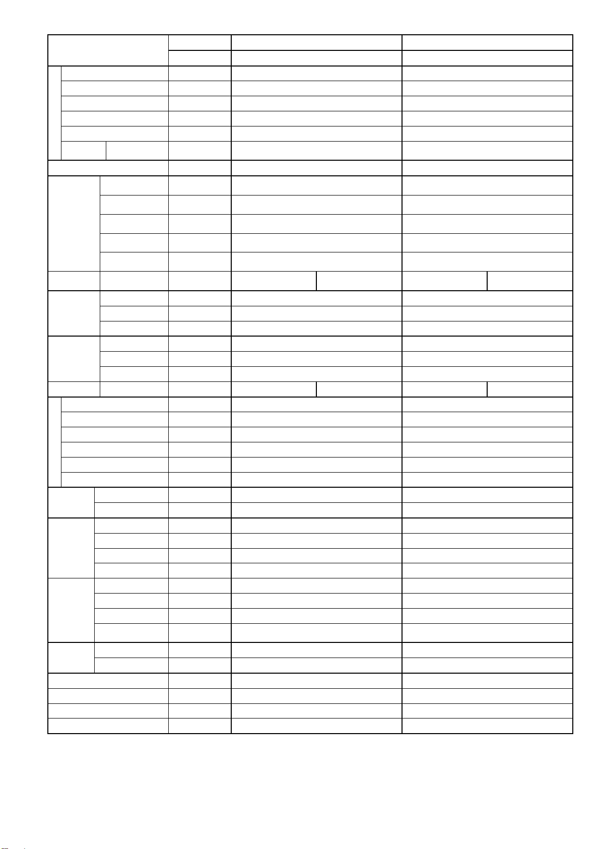
Model
Type Propeller Propeller
Material PP PP
Motor Type DC (8 poles) DC (8 poles)
Input Power W - -
Outdoor Fan
Indoor Airflow
Outdoor
Refrigeration
Dimension
Piping
Drain Hose
Indoor Heat
Exchanger
Outdoor
Exchanger
Air Filter
Output Power W 40 40
Speed Hi rpm C: 830 H: 780 C: 830 H: 820
Moisture Removal L/h (Pt/h) 0.6 (1.3) 0.8 (1.7)
QLo m
Lo m3/min (ft3/min)
Me m3/min (ft3/min)
Hi m3/min (ft3/min)
SHi m3/min (ft3/min)
Airflow
Cycle
Weight Net (I/D / O/D) kg (lb) 9 (20) 37 (82) 9 (20) 37 (82)
Pipe Diameter (Liquid / Gas) mm (inch) 6.35 (1/4) / 9.52 (3/8) 6.35 (1/4) / 12.70 (1/2)
Standard length m (ft) 7.5 (24.6) 7.5 (24.6)
Length range (min – max) m (ft) 3 (9.8) ~ 20 (65.6) 3 (9.8) ~ 20 (65.6)
I/D & O/D Height different m (ft) 15 (49.2) 15 (49.2)
Additional Gas Amount g/m (oz/ft) 20 (0.2) 20 (0.2)
Length for Additional Gas m (ft) 7.5 (24.6) 7.5 (24.6)
Row x Stage x FPI 2 x 15 x 21 2 x 15 x 21
Heat
Row x Stage x FPI 2 x 24 x 17 2 x 24 x 17
Power Supply Outdoor Outdoor
Power Supply Cord A - -
Thermostat - -
Protection Device - -
Hi m
Control Device Expansion Valve Expansion Valve
Refrigerant Oil cm3 FV50S (320) FV50S (320)
Refrigerant Type g (oz) R410A, 980 (34.6) R410A, 1.08k (38.1)
Height(I/D / O/D) mm (inch) 290 (11-7/16) / 540 (21-9/32) 290 (11-7/16) / 540 (21-9/32)
Width (I/D / O/D) mm (inch) 870 (34-9/32) / 780 (30-23/32) 870 (34-9/32) / 780 (30-23/32)
Depth (I/D / O/D) mm (inch) 214 (8-7/16) / 289 (11-13/32) 214 (8-7/16) / 289 (11-13/32)
Inner Diameter mm (inch) 16.7 (5/8) 16.7 (5/8)
Length mm (inch) 650 (25-5/8) 650 (25-5/8)
Fin Material Aluminium (Pre Coat) Aluminium (Pre Coat)
Fin Type Slit Fin Slit Fin
Size (W x H x L) inch 1 x 12-13/32 x 24 1 x 12-13/32 x 24
Fin Material Aluminium (Blue coated) Aluminium (Blue coated)
Fin Type Corrugate Fin Corrugate Fin
Size (W x H x L) inch
Material Polypropelene Polypropelene
Type One-touch One-touch
Indoor CS-E9RKUAW CS-E12RKUAW
Outdoor CU-E9RKUA CU-E12RKUA
3
/min (ft3/min)
3
/min (ft3/min)
Cooling : 6.28 (222)
Heating : 7.08 (250)
Cooling : 7.40 (261)
Heating : 8.20 (290)
Cooling : 9.64 (340)
Heating : 10.55 (373)
Cooling : 12.0 (425)
Heating : 12.9 (455)
Cooling : 13.00 (459)
Heating : 13.91 (491)
Cooling : 31.0 (1095)
Heating : 31.0 (1095)
1-13/32 x 19-13/16 x 28-1/16
26-7/8
Cooling : 5.97 (211)
Heating : 9.37 (331)
Cooling : 7.76 (274)
Heating : 10.49 (370)
Cooling : 10.22 (361)
Heating : 12.40 (438)
Cooling : 12.8 (450)
Heating : 14.3 (505)
Cooling : 14.14 (499)
Heating : 15.08 (532)
Cooling : 31.2 (1100)
Heating : 31.2 (1100)
1-13/32 x 19-13/16 x 32-7/16
31-1/4
6
Page 7
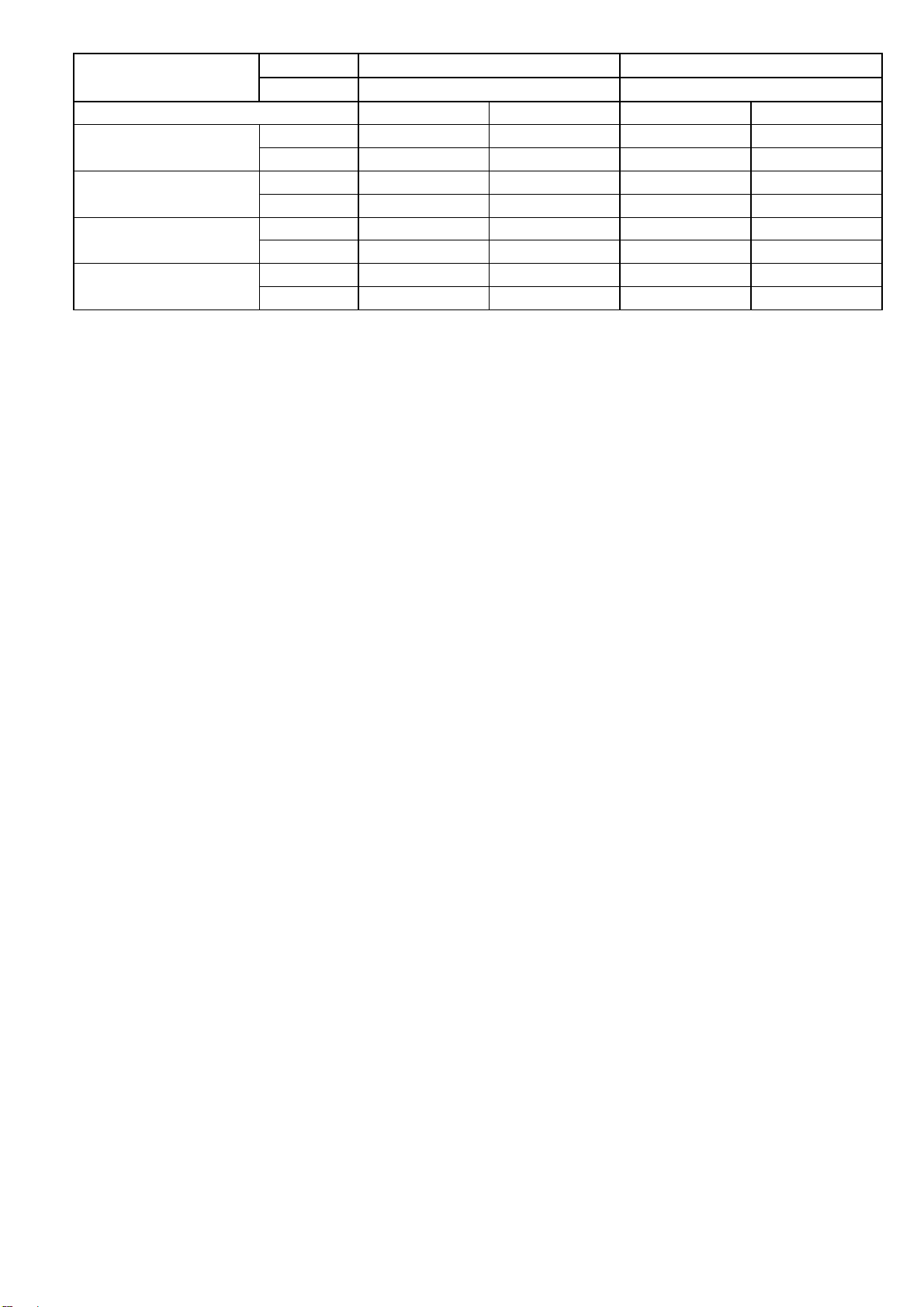
Model
DRY BULB WET BULB DRY BULB WET BULB
Indoor Operation Range
(Cooling) (°F / °C)
Outdoor Operation Range
(Cooling) (°F / °C)
Indoor Operation Range
(Heating) (°F / °C)
Outdoor Operation Range
(Heating) (°F / °C)
1. Cooling capacities are based on indoor temperature of 27°C DRY BULB (80.6°F DRY BULB), 19.0°C WET BULB (66°F WET BULB) and
outdoor air temperature of 35°C DRY BULB (95°F DRY BULB), 24°C WET BULB (75.2°F WET BULB)
2. Heating capacities are based on indoor temperature of 20°C Dry Bulb (68°F Dry Bulb) and outdoor air temperature of 7°C Dry Bulb (44.6°F
Dry Bulb), 6°C Wet Bulb (42.8°F Wet Bulb)
3. Specifications are subjected to change without prior notice for further improvement.
Indoor CS-E9RKUAW CS-E12RKUAW
Outdoor CU-E9RKUA CU-E12RKUA
Maximum 89.6 / 32 73.4 / 23 89.6 / 32 73.4 / 23
Minimum 60.8 / 16 51.8 / 11 60.8 / 16 51.8 / 11
Maximum 114.8 / 46 78.8 / 26 114.8 / 46 78.8 / 26
Minimum 0 / -17.8 - / - 0 / -17.8 - / -
Maximum 86.0 / 30 - / - 86.0 / 30 - / -
Minimum 60.8 / 16 - / - 60.8 / 16 - / -
Maximum 75.2 / 24 64.4 / 18 75.2 / 24 64.4 / 18
Minimum -4 / -20 -5.8 / -21 -4 / -20 -5.8 / -21
7
Page 8
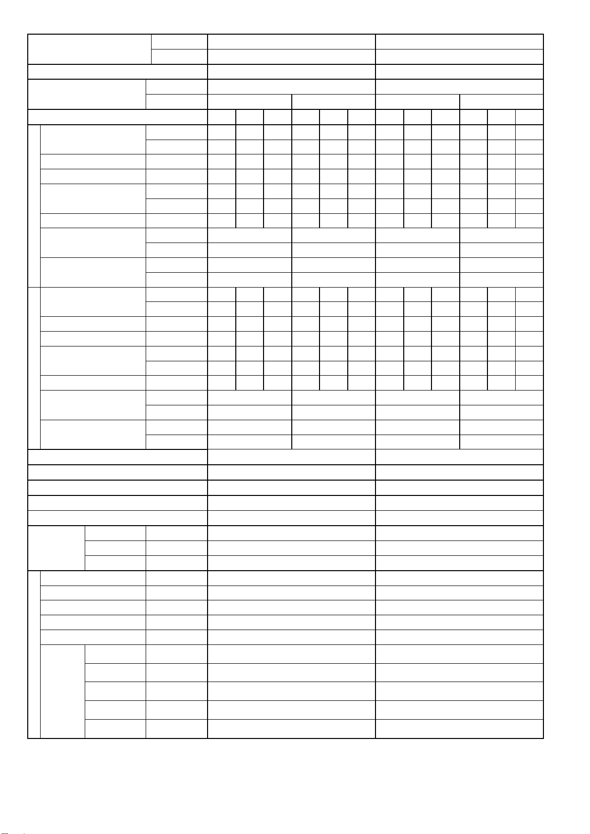
Model
Performance Test Condition ARI ARI
Power Supply
Min. Mid. Max. Min. Mid. Max. Min. Mid. Max. Min. Mid. Max.
Capacity
Running Current A - 7.00 - - 6.30 - - 11.90 - - 10.80 -
Input Power W 430 1.30k 1.60k 430 1.30k 1.60k 430 2.35k 2.72k 430 2.35k 2.72k
EER
Cooling
Heating
Compressor
Indoor Fan
Power Factor % - 89 - - 90 - - 95 - - 95 -
Indoor Noise (H / L / QLo)
Outdoor Noise (H / L / QLo)
Capacity
Running Current A - 9.30 - - 8.30 - - 12.60 - - 11.40 -
Input Power W 380 1.75k 1.80k 380 1.75k 1.80k 380 2.50k 2.66k 380 2.50k 2.66k
COP
Power Factor % - 90 - - 92 - - 95 - - 95 -
Indoor Noise (H / L / QLo)
Outdoor Noise (H / L / QLo)
Max Current (A) / Max Input Power (W) 12.7 / 2.69k 13.7 / 3.06k
Starting Current (A) 9.3 12.6
Min Circuit Ampacity 15.0 20.0
Max. Overcurrent Protection 20.0 25.0
SEER / HSPF 19.50 / 10.00 19.00 / 10.00
Type Hermetic Motor / Rotary Hermetic Motor / Rotary
Motor Type Brushless (4 poles) Brushless (4 poles)
Output Power W 1.7k 1.7k
Type Cross-flow fan Cross-flow fan
Material ASG30K1 ASG30K1
Motor Type DC (8 poles) DC (8 poles)
Input Power W 94.8 - 94.8 94.8 - 94.8
Output Power W 40 40
QLo rpm
Lo rpm
Speed
Me rpm
Hi rpm
SHi rpm
Indoor CS-E18RKUAW CS-E24RKUAW
Outdoor CU-E18RKUA CU-E24RKUA
Phase, Hz Single, 60 Single, 60
V 208 230 208 230
kW 1.70 5.04 5.80 1.70 5.04 5.80 1.70 7.02 8.00 1.70 7.02 8.00
BTU/h 5800 17200 19800 5800 17200 19800 5800 24000 27200 5800 24000 27200
W/W 3.95 3.88 3.63 3.95 3.88 3.63 3.95 2.99 2.94 3.95 2.99 2.94
Btu/hW 13.45 13.20 12.35 13.45 13.20 12.35 13.45 10.20 10.00 13.45 10.20 10.00
dB-A 47 / 39 / 36 47 / 39 / 36 48 / 40 / 37 48 / 40 / 37
Power Level dB 63 / - / - 63 / - / - 64 / - / - 64 / - / -
dB-A 49 / - / - 49 / - / - 51 / - / - 51 / - / -
Power Level dB 63 / - / - 63 / - / - 65 / - / - 65 / - / -
kW 1.70 6.33 6.43 1.70 6.33 6.43 1.70 8.46 8.56 1.70 8.46 8.56
BTU/h 5800 21600 22000 5800 21600 22000 5800 28800 29200 5800 28800 29200
W/W 4.47 3.62 3.57 4.47 3.62 3.57 4.47 3.38 3.22 4.47 3.38 3.22
Btu/hW 15.25 12.30 12.20 15.25 12.30 12.20 15.25 11.50 10.95 15.25 11.50 10.95
dB-A 46 / 39 / 36 46 / 39 / 36 48 / 40 / 37 48 / 40 / 37
Power Level dB 62 / - / - 62 / - / - 64 / - / - 64 / - / -
dB-A 51 / - / - 51 / - / - 53 / - / - 53 / - / -
Power Level dB 65 / - / - 65 / - / - 67 / - / - 67 / - / -
Cooling : 970
Heating : 1030
Cooling : 1060
Heating : 1120
Cooling : 1220
Heating : 1260
Cooling : 1380
Heating : 1410
Cooling : 1480
Heating : 1500
Cooling : 1000
Heating : 1110
Cooling : 1090
Heating : 1220
Cooling : 1240
Heating : 1360
Cooling : 1400
Heating : 1500
Cooling : 1500
Heating : 1600
8
Page 9
Model
Type Propeller Propeller
Material PP PP
Motor Type DC Motor (8 poles) DC Motor (8 poles)
Input Power W - -
Outdoor Fan
Indoor Airflow
Outdoor
Refrigeration
Dimension
Piping
Drain Hose
Indoor Heat
Exchanger
Outdoor
Exchanger
Air Filter
Output Power W 60 60
Speed Hi rpm
Moisture Removal L/h (Pt/h) 1.4 (3.0) 3.6 (7.6)
QLo m
Lo m3/min (ft3/min)
Me m3/min (ft3/min)
Hi m3/min (ft3/min)
SHi m3/min (ft3/min)
Airflow
Cycle
Weight Net (I/D / O/D) kg (lb) 12 (26) 60 (132) 12 (26) 60 (132)
Pipe Diameter (Liquid / Gas) mm (inch) 6.35 (1/4) / 12.70 (1/2) 6.35 (1/4) / 15.88 (5/8)
Standard length m (ft) 7.5 (24.6) 7.5 (24.6)
Length range (min – max) m (ft) 3 (9.8) ~ 30.5 (100.0) 3 (9.8) ~ 30.5 (100.0)
I/D & O/D Height different m (ft) 15 (49.2) 15 (49.2)
Additional Gas Amount g/m (oz/ft) 25 (0.3) 25 (0.3)
Length for Additional Gas m (ft) 10 (32.8) 10 (32.8)
Row x Stage x FPI 2 x 15 x 21 2 x 15 x 21
Heat
Row x Stage x FPI 2 x 36 x 19 2 x 36 x 19
Power Supply Outdoor Outdoor
Power Supply Cord A - -
Thermostat - -
Protection Device - -
Hi m
Control Device Expansion Valve Expansion Valve
Refrigerant Oil cm3 FV50S (800) FV50S (800)
Refrigerant Type g (oz) R410A, 1.60k (56.5) R410A, 1.85k (65.3)
Height(I/D / O/D) mm (inch) 290 (11-7/16) / 795 (31-5/16) 290 (11-7/16) / 795 (31-5/16)
Width (I/D / O/D) mm (inch) 1070 (42-5/32) / 875 (34-15/32) 1070 (42-5/32) / 875 (34-15/32)
Depth (I/D / O/D) mm (inch) 240 (9-15/32) / 320 (12-5/8) 240 (9-15/32) / 320 (12-5/8)
Inner Diameter mm (inch) 16.7 (5/8) 16.7 (5/8)
Length mm (inch) 650 (25-5/8) 650 (25-5/8)
Fin Material Aluminium (Pre Coat) Aluminium (Pre Coat)
Fin Type Slit Fin Slit Fin
Size (W x H x L) inch 1 x 12-13/32 x 31-7/8 1 x 12-13/32 x 31-7/8
Fin Material Aluminium (Blue coated) Aluminium (Blue coated)
Fin Type Corrugate Fin Corrugate Fin
Size (W x H x L) inch
Material Polypropelene Polypropelene
Type One-touch One-touch
Indoor CS-E18RKUAW CS-E24RKUAW
Outdoor CU-E18RKUA CU-E24RKUA
3
/min (ft3/min)
3
/min (ft3/min)
Cooling: 700
Heating: 700
Cooling : 13.28 (469)
Heating : 14.40 (508)
Cooling : 14.53 (513)
Heating : 15.65 (553)
Cooling : 16.77 (592)
Heating : 17.61 (622)
Cooling : 19.00 (670)
Heating : 19.70 (695)
Cooling : 20.40 (720)
Heating : 20.96 (740)
Cooling : 54.5 (1925)
Heating : 54.5 (1925)
1-13/32 x 29-25/32 x 34-7/32
35-5/16
Cooling : 54.5 (1925)
Heating : 54.5 (1925)
Cooling : 54.9 (1940)
Heating : 56.5 (1995)
Cooling: 730
Heating: 750
Cooling : 13.42 (474)
Heating : 14.86 (525)
Cooling : 14.67 (518)
Heating : 16.39 (579)
Cooling : 16.77 (592)
Heating : 18.35 (648)
Cooling : 19.00 (670)
Heating : 20.30 (715)
Cooling : 20.40 (720)
Heating : 21.70 (766)
Cooling : 54.9 (1940)
Heating : 56.5 (1995)
1-13/32 x 29-25/32 x 34-7/32
35-5/16
9
Page 10
Model
DRY BULB WET BULB DRY BULB WET BULB
Indoor Operation Range
(Cooling) (°F / °C)
Outdoor Operation Range
(Cooling) (°F / °C)
Indoor Operation Range
(Heating) (°F / °C)
Outdoor Operation Range
(Heating) (°F / °C)
1. Cooling capacities are based on indoor temperature of 80°F DRY BULB, 67°F WET BULB and outdoor air temperature of 95°F DRY BULB,
75°F WET BULB.
2. Heating capacities are based on indoor temperature of 70°F DRY BULB, 60°F WET BULB and outdoor air temperature of 47°F DRY BULB,
43°F WET BULB.
3. Specifications are subjected to change without prior notice for further improvement.
Indoor CS-E18RKUAW CS-E24RKUAW
Outdoor CU-E18RKUA CU-E24RKUA
Maximum 89.6 / 32 73.4 / 23 89.6 / 32 73.4 / 23
Minimum 60.8 / 16 51.8 / 11 60.8 / 16 51.8 / 11
Maximum 114.8 / 46 78.8 / 26 114.8 / 46 78.8 / 26
Minimum 0 / -17.8 - / - 0 / -17.8 - / -
Maximum 86.0 / 30 - / - 86.0 / 30 - / -
Minimum 60.8 / 16 - / - 60.8 / 16 - / -
Maximum 75.0 / 24 64.4 / 18 75.0 / 24 64.4 / 18
Minimum -4 / -20 -5.8 / -21 -4 / -20 -5.8 / -21
10
Page 11

3. Features
Inverter Technology
o Wider output power range
o Energy saving
o Quick Cooling
o More precise temperature control
Environment Protection
o Non-ozone depletion substances refrigerant (R410A)
Long Installation Piping
o CS/CU-E9/12RK, long piping up to 65 feet (20 meters)
o CS/CU-E18/24RK, long piping up to 100 feet (30 meters)
Easy to use remote control
Quality Improvement
o Random auto restart after power failure for safety restart operation
o Gas leakage protection
o Prevent compressor reverse cycle
o Inner protector to protect Compressor
o Noise prevention during soft dry operation
Operation Improvement
o Quiet mode to reduce the indoor unit operating sound
o Powerful mode to reach the desired room temperature quickly
Serviceability Improvement
o Breakdown Self Diagnosis function
11
Page 12
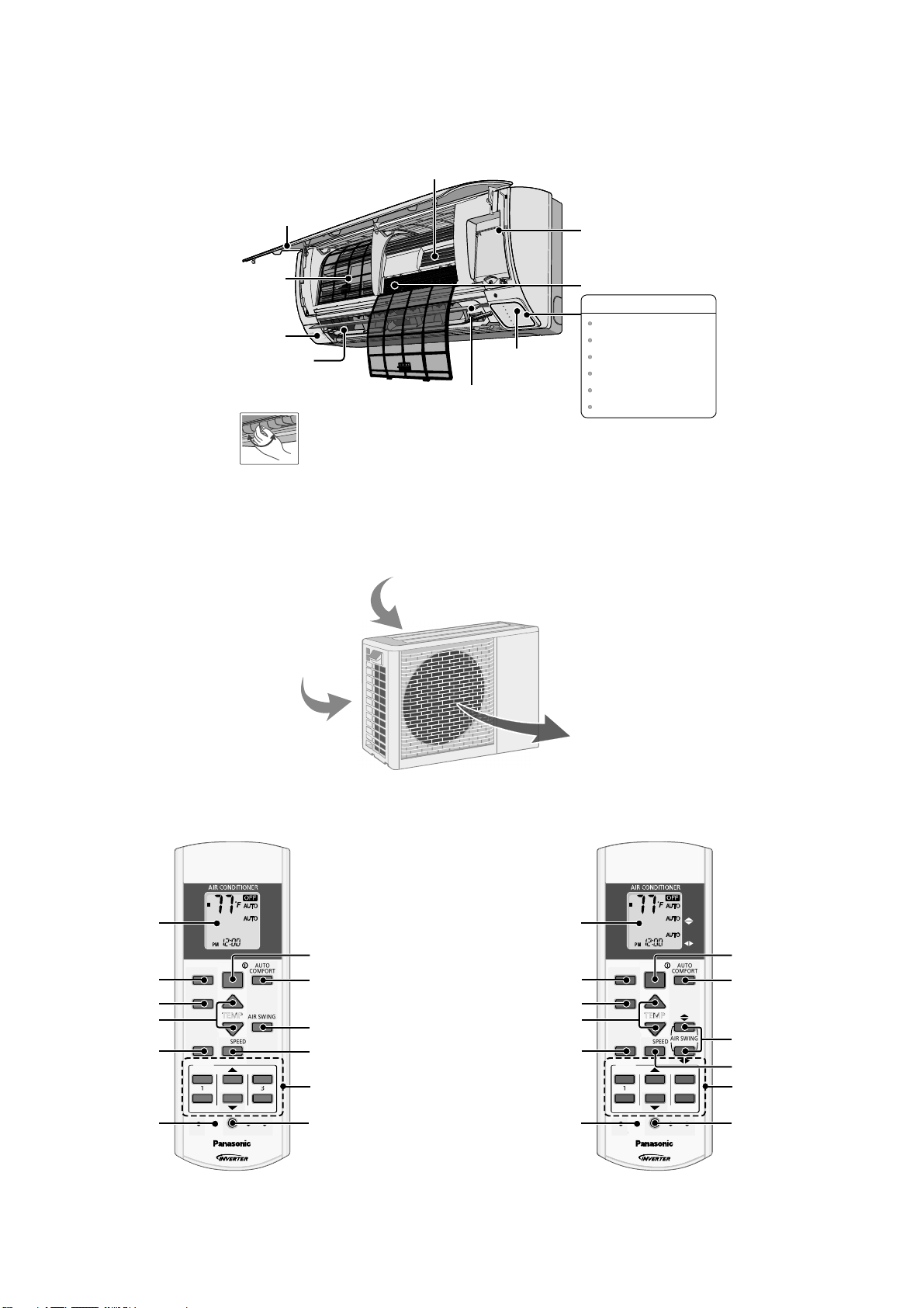
4. Location of Controls and Components
Alu
miniu
mFin
A
TEMP
OFF/O
N
TIMER
S
CANCEL
O
N
OFF2
CHEC
K
TEMP
OFF/O
N
TIMER
S
CANCEL
O
N
OFF2
3
CHEC
K
4.1 Indoor Unit
Front Panel
Air Filters
Human activity
sensor
Horizontal Airflow
Direction Louver
• Manually adjustable
(E9RK and E12RK).
• Do not adjust by hand
(E18RK and E24RK).
4.2 Outdoor Unit
ir inlet (side)
Air inlet (rear)
R
E
W
O
P
R
E
M
I
T
I
V
A
N
O
C
E
T
R
O
F
M
O
C
O
T
U
A
L
U
F
R
E
W
O
P
T
E
I
U
Q
Remote control
receiver and Indicator
Vertical Airflow
Direction Louver
• Do not adjust by hand.
Auto OFF/ON button
Air Purifying Filter
INDICATOR
POWER
TIMER
ECONAVI
AUTO COMFORT
POWERFUL
QUIET
(Green)
(Orange)
(Green)
(Green)
(Orange)
(Orange)
4.3 Remote Control
OFF/ON
TEMP
FAN SPEED
2
AUTO
COMFORT
AIR SWING
SET
CANCEL
AC
FAN
SPEED
AIR
SWING
ET
3
RC
Remote control
display
Econavi operation
Operation mode
Temperature setting
Powerful/Sleep mode
operation
Check Check
AUTO
HEAT
COOL
DRY
FAN
ECONAVI
MODE
POWERFUL/
QUIET
TIMER
ON
1
OFF
SET CHECK CLO CK RESET
E9RK E12RK E18RK E24RK
OFF/ON
Auto comfort operation
Vertical airflow
direction selection
Fan speed selection
Timer setting
Clock setting
Remote control
display
Econavi operation
Operation mode
Temperature setting
Powerful/Sleep mode
operation
Air outlet
AUTO
HEAT
COOL
DRY
FAN
OFF/ON
ECONAVI
MODE
TEMP
POWERFUL/
FAN SPEED
QUIET
TIMER
ON
1
2
OFF
SET CHECK CL OCK RESET
AUTO
COMFORT
AIR SWING
SET
CANCEL
AC
FAN
SPEED
AIR
SWING
ET
3
RC
OFF/ON
Auto comfort operation
Airflow direction
selection
Fan speed selection
Timer setting
Clock setting
12
Page 13
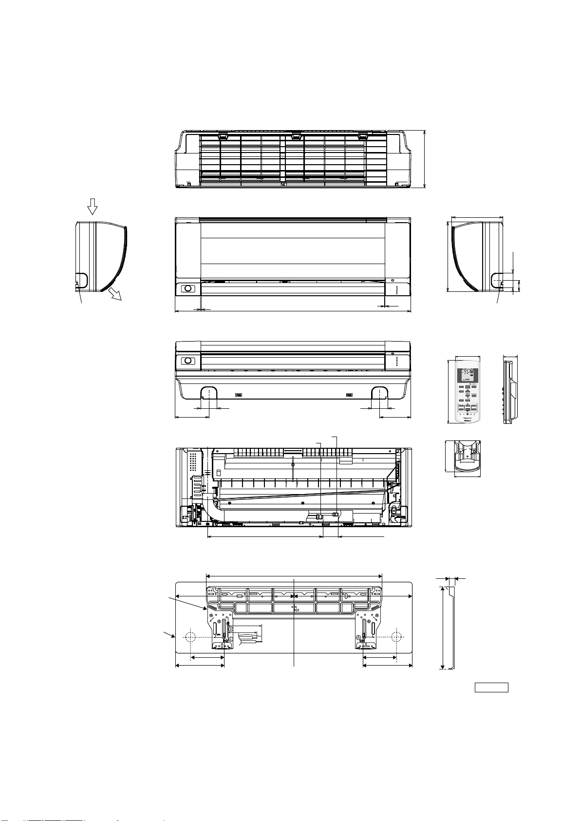
5. Dimensions
/
TEM
OFF/O
N
S
O
123
CHEC
K
5.1 Indoor Unit
5.1.1 CS-E9RKUAW CS-E12RKUAW
<Side View> <Side View>
Air intake
direction
<Top View>
<Front View>
(8-7/16)
8-7/16
Left piping
hole
Air outlet
direction
1/32~1/16
<Bottom View>
4-29/32
<Rear View>
16-1/8
34-9/32
Liquid si de
Gas s ide
2-11/322-11/32
(1-5/8~2-13/32)
1/32~1/16
4-17/32
11- 7/ 16
Right piping
hole
Remote control
1-7/8
FAN
AUTO
SPEED
HEAT
AIR
COOL
SWING
DRY
FAN
AUTO
OFF/ON
ECONAVI
COMFORT
MODE
TEMP
P
AIRSWING
POWERFUL/
FANSPEED
QUIET
5-1/4
TIMER
TIMER
SET
ET
N
123
CANCELONOFF
CANCEL
OFF
AC
RC
SETC HECKCLOCK R ESET
Remote control holder
2-3/8
2
2-13/32
1-49/64
7/8
Relative position between the indoor unit and the installation plate <Front View>
Installation
plate
Indoor unit
external
dimensions
line
29-29/64
Left
piping
hole
3-3/4
1-11/16
5-1/16
9-17/32 9-17/32
5-1/16
1717-9/32
Right
piping
hole
5/8
10-3/8
Unit: inch
13
Page 14
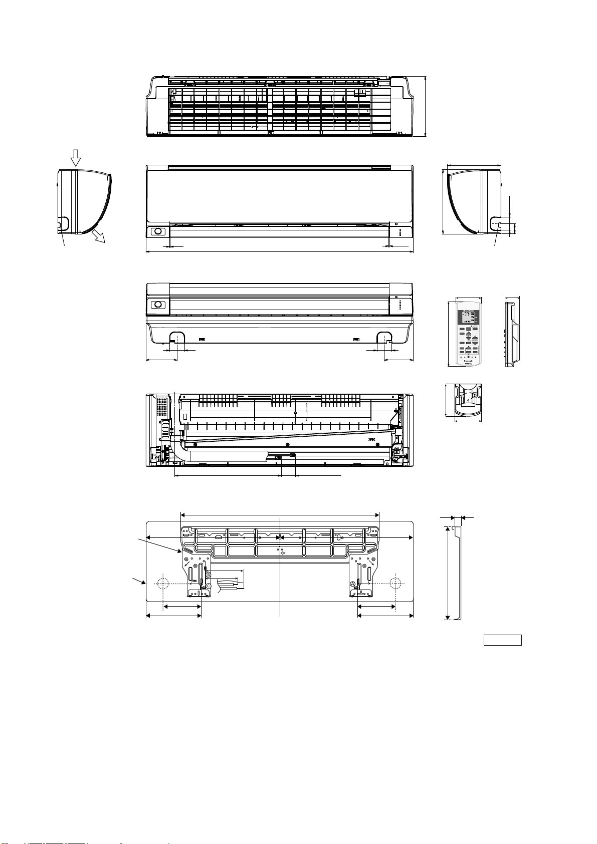
5.1.2 CS-E18RKUAW CS-E24RKUAW
TEM P
OFF/O
N
T
S
OFF123
CHEC
K
<Top View>
<Side View> <Side View>
Air intake
direction
<Front View>
(9-15/32)
9-15/32
Left piping
hole
Air outlet
direction
1/32~1/16
42-5/32
<Bottom View>
2-11/32
<Rear View>
16-9/64
(1-39/64~2-13/32)
Relative position between the indoor unit and the installation plate <Front View>
29-7/16
2-11/32
1/32~1/16
4-17/324-29/32
11- 7/ 16
Right piping
hole
Remote control
1-7/8
AUTO
FAN
SPEED
HEAT
COOL
DRY
AIR
SWING
FAN
AUTO
OFF/ON
ECONAVI
COMFORT
MODE
TEMP
POWERFUL/
AIRSWING
QUIET
FANSPEED
5-1/4
TIMER
IMER
SET
ET
ON
123
CANCELONOFF
CANCEL
AC
RC
SETCHECK CLOCK RESET
Remote control holder
2-3/8
2
5/8
2-13/32
1-49/64
7/8
Installation
plate
Indoor unit
external
dimensions
line
Left
piping
hole
8-5/8
6-21/32
5-1/16
9-17/32 9-17/32
14
5-1/16
20-15/1621-7/32
Right
piping
hole
10-3/8
Unit: inch
Page 15
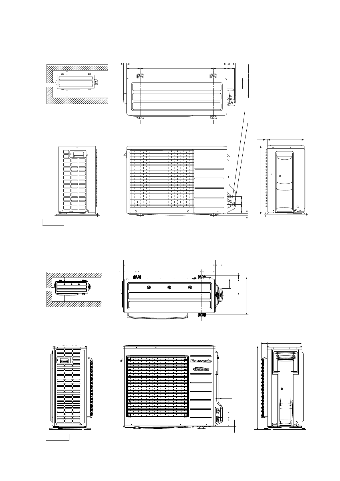
5.2 Outdoor Unit
5.2.1 CU-E9RKUA CU-E12RKUA
Space necessary for
installation
3-7/8
<Top View>
(4-1/8)
30-23/321
22-1/2
2-5/8
4-1/8 2-3/8
1-3/86-1/8
3-7/8
39-3/8
Anchor Bolt Pitch
12-5/8 x 22-1/2
<Side View> <Front View>
Unit : inch
5.2.2 CU-E18RKUA CU-E24RKUA
<Top View>
3-3/8
2-way valve at Liquid side
(High Pressure)
3-way valve at Gas side
(Low Pressure)
<Side View>
1/2
21-9/32
(3/4)
(2-3/4) (2-3/8)
11- 13 /32
Space necessary for
3-7/8
Anchor Bolt Pitch
15-5/64 x 24-7/64
<Side View>
installation
3-7/8
39-3/8
1-5/64
(5-5/32)
<Front View>
34-15/32
24-1/8 5-5/32
2-3/4
3-7/32
2-17/32
2-61/64
2-3/4
1-1/2
5-31/32
14-3/16
<Side View>
2-5/16
31-5/16
(31/32)
12-5/8
Unit: inch
15
Page 16
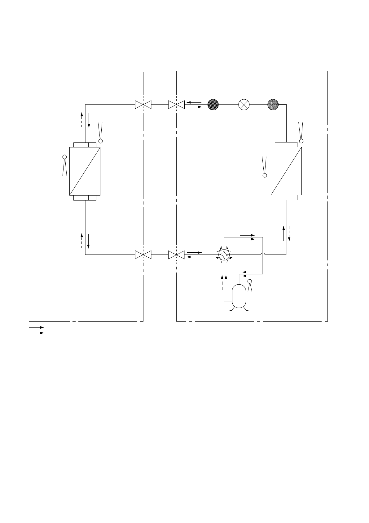
6. Refrigeration Cycle Diagram
DOOROUTDOOR
G
6.1 CU-E9RKUA CU-E12RKUA
IN
INTAKE
TEMP.
SENSOR
HEAT EXCHANGER
(EVAPORATOR)
PIPE
TEMP.
SENSOR
LIQUID
SIDE
2-WAY
VALV E
GAS
SIDE
3-WAY
VALV E
DISCHARGE
MUFFLER
4-WAY VALVE
EXP ANSION
VALV E
INTAKE
TEMP.
SENSOR
HEAT EXCHANGER
(CONDENSER)
STRAINER
PIPE
TEMP.
SENSOR
COMPRESSOR
TEMP. SENSOR
COMPRESSOR
COOLING
HEAT I N
16
Page 17
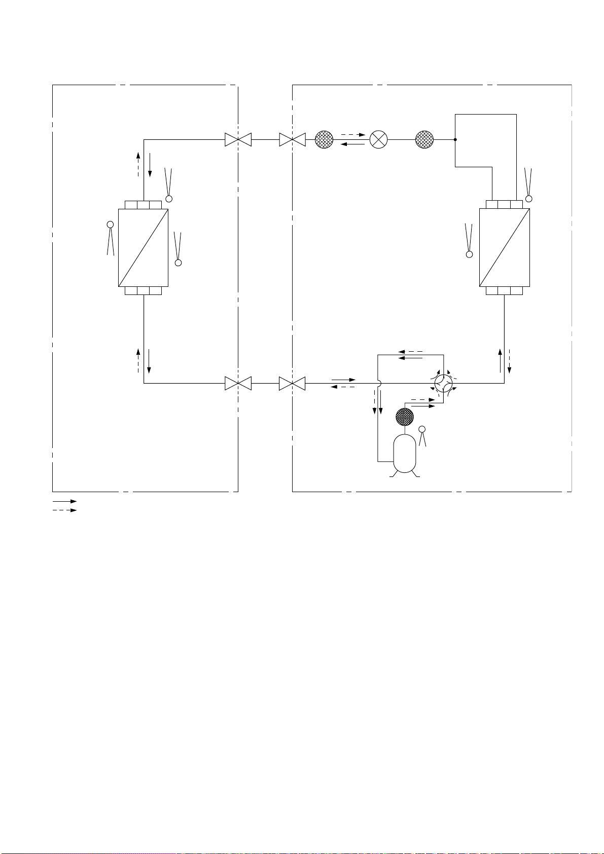
6.2 CU-E18RKUA CU-E24RKUA
U
T
H
EATIN
G
INDOOR O
DOOR
INTAKE
TEMP.
SENSOR
HEAT EXCHANGER
(EVAPORATOR)
PIPE
TEMP.
SENSOR 1
PIPE
TEMP.
SENSOR 2
LIQUID
SIDE
2-WAY
VALV E
GAS
SIDE
3-WAY
VALV E
EXP ANSION
VALV E
STRAINERRECEIVER
PIPE
TEMP.
SENSOR
INTAKE
TEMP.
SENSOR
HEAT EXCHANGER
(CONDENSER)
4-WAY VALVE
DISCHARGE MUFFLER
COOLING
COMPRESSOR
DISC. SENSOR
COMPRESSOR
17
Page 18
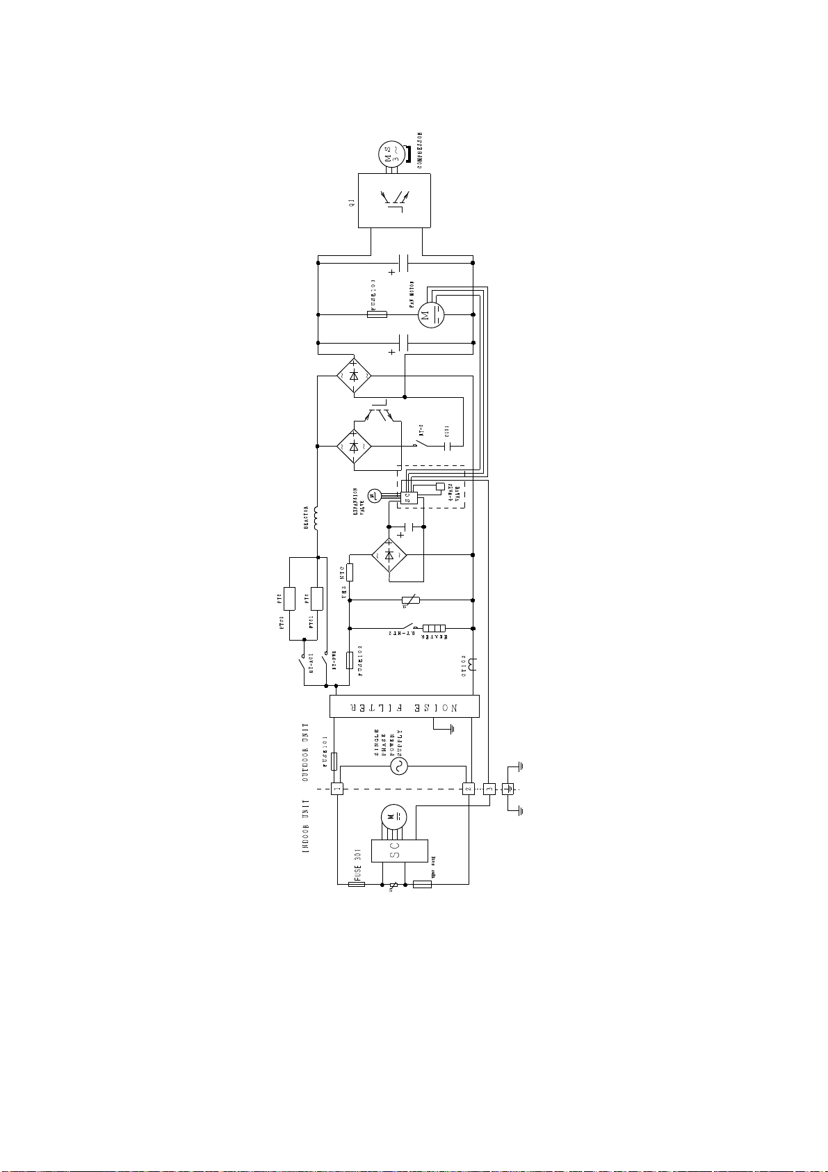
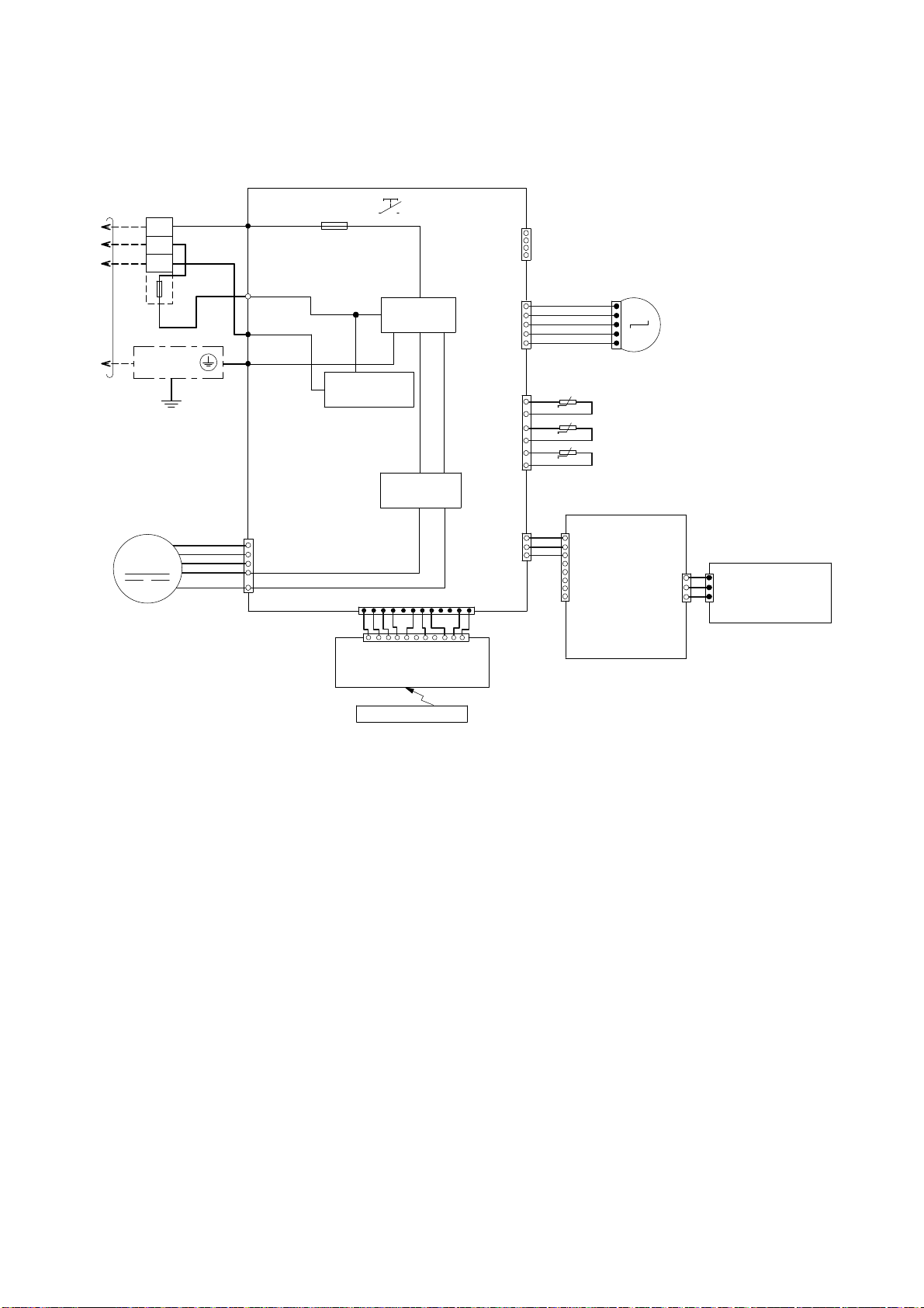
7. Block Diagram
7.1 CS-E9RKUAW CU-E9RKUA CS-E12RKUAW CU-E12RKUA
18
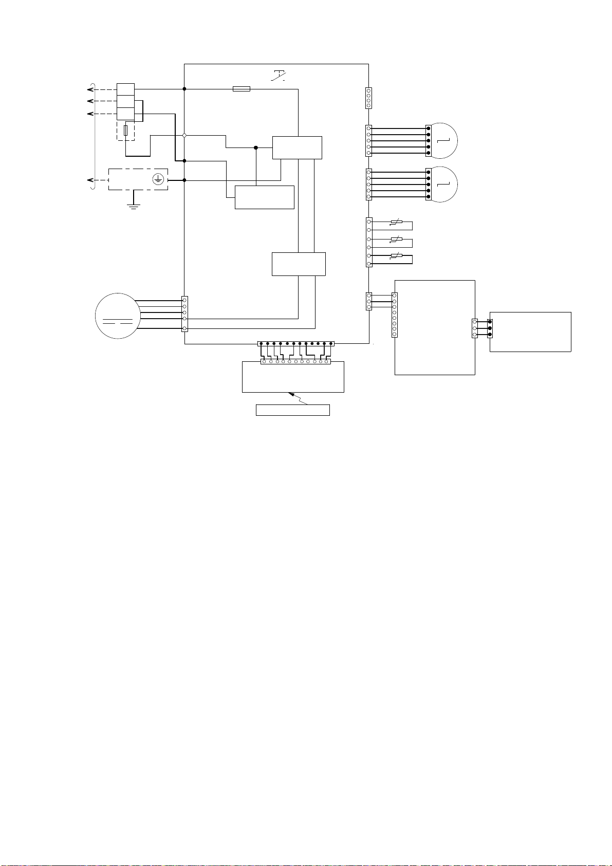
Page 19
7.2 CS-E18RKUAW CU-E18RKUA CS-E24RKUAW CU-E24RKUA
19
Page 20
8. Wiring Connection Diagram
8.1 Indoor Unit
8.1.1 CS-E9RKUAW CS-E12RKUAW
TERMINAL
TO
OUTDOOR
UNIT
BOARD
TEMP.
FUSE
102°C
(3A)
GROUNDING
TERMINAL
EVAPORATOR
1
2
3
Y/G
BL
W
R
AC306 (BLK)
AC303 (WHT)
AC304 (RED)
G301 (GRN)
G
FUSE301
T3.15A L250V
COMMUNICATION
CIRCUIT
NOISE FILTER
RECTIFICATION
AUTO SW
(SW01)
CIRCUIT
CIRCUIT
REMARKS
B : BLUE P : PINK
4
(WHT)
1
CN–RMT
1
(WHT)
CN–STM1
5
6
(RED)
CN–TH
1
BR
R
O
Y
P
t
t
t
1
5
PIPING TEMP. SENSOR 2
(THERMISTOR)
PIPING TEMP. SENSOR 1
(THERMISTOR)
SUCTION TEMP. SENSO R
(THERMISTOR)
BR : BROWN O : ORANGE
BL : BLACK Y : YELLOW
W : WHITE G : GREEN
R : RED
Y/G : YELLOW /GREEN
UP DOWN
M
LOUVER MOTOR
FAN MOTOR
M
Y
7
B
6
W
5
BL
4
R
1
CONTROLLER
CN–FM (WHT)
(MAIN)
CN
–DISP (YLW)
1
WWWWWWWWW
11
CN–DISP (WHT)
ELECTRONIC CONTROLLER
(DISPLAY & RECEIVER)
REMOTE CONTROLLER
12
1
ELECTRONIC
3
1
(WHT)
CN–MSENS
W
1
W
W
W
1
(WHT)
CN–MSENS
8
ELECTRONIC CONTROLLER
(COMPARATOR)
(WHT)
CN–SENS1
1
SENS1
3
–
CN
ELECTRONIC
CONTROLLER
(YLW)
(ECO SENSOR)
W
W
3
20
Page 21
8.1.2 CS-E18RKUAW CS-E24RKUAW
TOO
TERMINAL
UTDOOR
UNIT
BOARD
TEMP.
FUSE
102°C
(3A)
GROUNDING
TERMINAL
EVAPORATOR
1
2
3
Y/G
BL
W
R
AC306 (BLK)
AC303 (WHT)
AC304 (RED)
G301 (GRN)
G
FUSE301
T3.15A L250V
COMMUNICATION
CIRCUIT
NOISE FILTER
RECTIFIC A TION
AUTO SW
(SW01)
CIRCUIT
CIRCUIT
CN–RMT
CN–STM1
CN–STM2
CN–TH
REMARKS
B : BLUE P : PINK
4
(WHT)
1
1
(WHT)
5
1
(YLW)
5
6
(RED)
1
BR
R
O
Y
P
BR
R
O
Y
P
PIPING TEMP. SENSOR 2
t
(THERMISTOR)
PIPING TEMP. SENSOR 1
t
(THERMISTOR)
SUCTION TEMP. SENSO R
t
(THERMISTOR)
BR : BROWN O : ORANGE
BL : BLACK Y : YELLOW
W : WHITE G : GREEN
R : RED
Y/G : YELLOW /GREEN
1
UP DOWN
M
LOUVER MOTOR
5
1
LEFT RIGHT
M
LOUVER MOTOR
5
FAN MOTOR
M
Y
7
B
6
W
5
BL
4
R
1
CONTROLLER
CN–FM (WHT)
(MAIN)
CN–DISP (YLW)
1
WWWWWWWWW
11
CN–DISP (WHT)
ELECTRONIC CONTROLLER
(DISPLAY & RECEIVER)
REMOTE CONTROLLER
12
1
ELECTRONIC
CN–MSENS
W
3
1
(WHT)
1
W
W
W
1
(WHT)
CN–MSENS
8
ELECTRONIC CONTROLLER
(WHT)
CN-SENS1
(COMPARATOR)
1
3
CN–SENS1
ELECTRONIC
CONTROLLER
(YLW)
(ECO SENSOR)
W
W
3
21
Page 22
8.2 Outdoor Unit
TOIN
U
N
T
ERSU
Y
8.2.1 CU-E9RKUA CU-E12RKUA
YELLOW (YLW)
CIRCUIT
RED (RED)
BLUE (BLU)
(TRADERMARK)
COMPRESSOR TERMINAL
ELECTRONIC CONTROLLER
THE PARENTHESIZED LETTERS IS
INDICATED ON TERMINAL COVER.
3~
MS
W
N
COMPRESSOR
SWITCHING
POWER SUPPLY
ELECTRONIC-MAGNETIC
1.711
1.741
1.765
5RS102XHA21
(THERMISTOR)
U-V
V-W
U-W
CONNECTION
Resistance of Compressor Windings
1
M
CN-STM
ELECTRONIC-MAGNETIC
COIL (EXPANSION VALVE)
REACTOR
16
RAT1
(GRY)
RAT2
(GRY)
GRY GRY
234
CN-TH
PFC
PIPING TEMP. SENSOR
CIRCUIT
FUSE 102
(THERMISTOR)
RECTIFICATION
T3.15A L250V
t°
t°
AIR TEMP. SENSOR
COMPRESSOR TEMP. SENSOR
(THERMISTOR)
CIRCUIT
1
t°
3
CN-TANK
CIRCUIT
RECTIFICATION
COIL (4-WAY VALVE)
BLU
YLW
Q1
RED
(RED)
P
(BLU)
(YLW)
V
U
FUSE 103
T3.15A l250v
YLW
YLW
1
3
CN-HOT
I
DOOR
PPL
POW
3
2
1
TERMINAL BOARD
(RED)
(BLACK)
(BLACK)
L1 L2
WHT RED
AC-BLK
(BLK)
CIRCUIT
NOISE FILTER
FUSE 101
20A 250V
AC-WHT
(WHT)
FG1 (GRN)
1
LJP101 (GRN)
456
CN-DCFM
7
HT2 (ORG)
1
CN4
1
5
(BLK)
CN5
(BLK)
ACL (BRW)BRW
5
CIRCUIT
COMMUNICATION
DATA (RED)
M
WHT
GRN
BLK
BLK
GRN
REMARKS;
BLACK; (BLK)
BLUE; (BLU)
WHITE; (WHT)
RED; (RED)
GRAY; (GRY)
GREEN; (GRN)
GRN
FAN
MOTOR
ELECTRONIC
CONTROLLER
ORG
HEATER
BROWN; (BRW)
ORANGE; (ORG)
YELLOW/GREEN; (YLW/GRN)
RY-HT2
ACL (BRW)
HT2 (ORG)
ORG
22
Page 23
8.2.2 CU-E18RKUA CU-E24RKUA
O
COMPRESSOR
RED
3
3
0.720Ω
0.726Ω
Resistance of Compressor Windings
0.708Ω
5KD240XAF21
U-V
V-W
U-W
CONNECTION
ELECTRONIC CONTROLLER (MAIN)
RED
(RED) U
U
Q10
PFC
CIRCUIT
~
3
MS
BLU
YLW
1
1
BLU
YLW
(YELLOW) W
(BLUE) V
V
W
P
N
SWITCHING POWER
HEATER
3
1
CN-HT
(BLACK)
RY-HT
SUPPLY CIRCUIT
11
OUTDOOR AIR
TEMP. SENSOR
(THERMISTOR)
CN-TH1
(WHITE)
t° t°
4
PIPING TEMP.
SENSOR
(THERMISTOR)
DC-FMG
YLW
DC-FMG
CN-DIS
(WHITE)
2
3
(BLUE)
CN-HOT
1
RY -HOT
16
CN-EV
(WHITE)
(YELLOW)
(YELLOW)
(WHITE)
CN-DCFM
7
4
1
t°
DISCHARGE TEMP.
SENSOR (THERMISTOR)
BLU
ELECTRO-MAGNETIC
COIL (4-WAY VALVE)
M
COIL
(EXPANSION VALVE)
ELECTRO-MAGNETIC
M
FAN M OTO R
7
7
YLW
BLU
44
11
BLK
RED
WHT
BLK
L2-0
(BLACK)
R
REACT
GRY
TO INDOO R UNIT
BLK
1
1
2
2
L2-1
GRY
(GRAY)
CN-COM
(YELLOW)
WHT
WHT
WHT
RED
WHT
11
44
FUSE2
AC-BL K
RECTIFICATION
(T 3.15A L 250V)
(BLACK)
BLK
CIRCUIT
FUSE1
(T 2.5A L 250V)
1
(WHITE)
AC-WHT
WHT
WHT
1
CIRCUIT
RECTIFICATION
CN-FM1
(WHITE)
DC-FM1
55
(ORANGE)
WHT
WHT
WHT
WHT
ORG
123
CN-BLK
TERMINAL
TERMINAL
BOARD
L2
L1
CN-COM
(YELLOW)
(RED)
WHT
BLK
COM3
FUSE3
ACL1
(25A, 250V)
(BLACK)
ACN1
(WHITE)
BOARD
BLK
(BLACK)
CIRCUIT
COMMUNICATION
(WHITE)
CN-WHT
CIRCUIT
NOISE FILTER
FG1
CN-FM1
(WHITE)
DC-FM1
(ORANGE)
ELECTRONIC CONTROLLER
(GREEN)
(NOISE FILTER)
POWER SUPPLY
RED
GRN WHT
YLW/GRN
GRN
YLW/GRN
YELLOW (YLW)
(RED)
BLUE
(BLU)
(TRADEMARK)
COMP. TERMINAL
INDICATED ON TERMINAL COVER
THE PARENTHESIZED LETTERS IS
23
Page 24
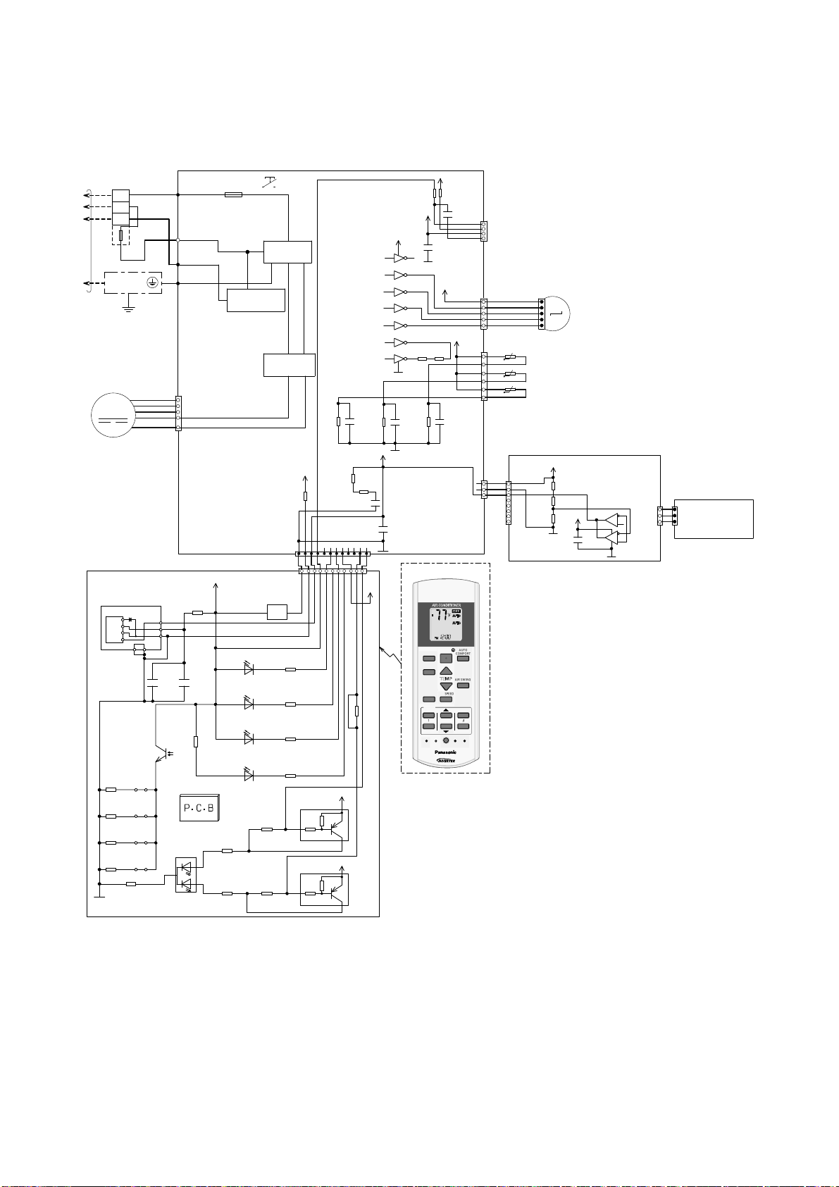
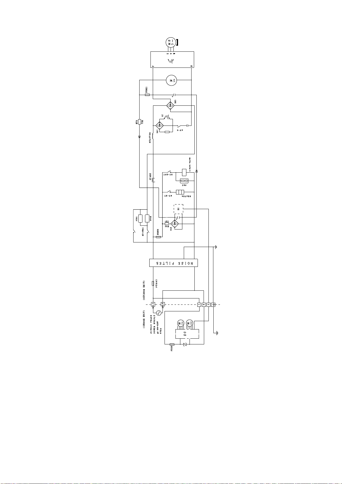
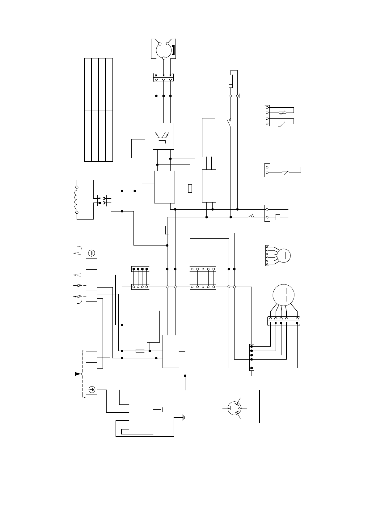
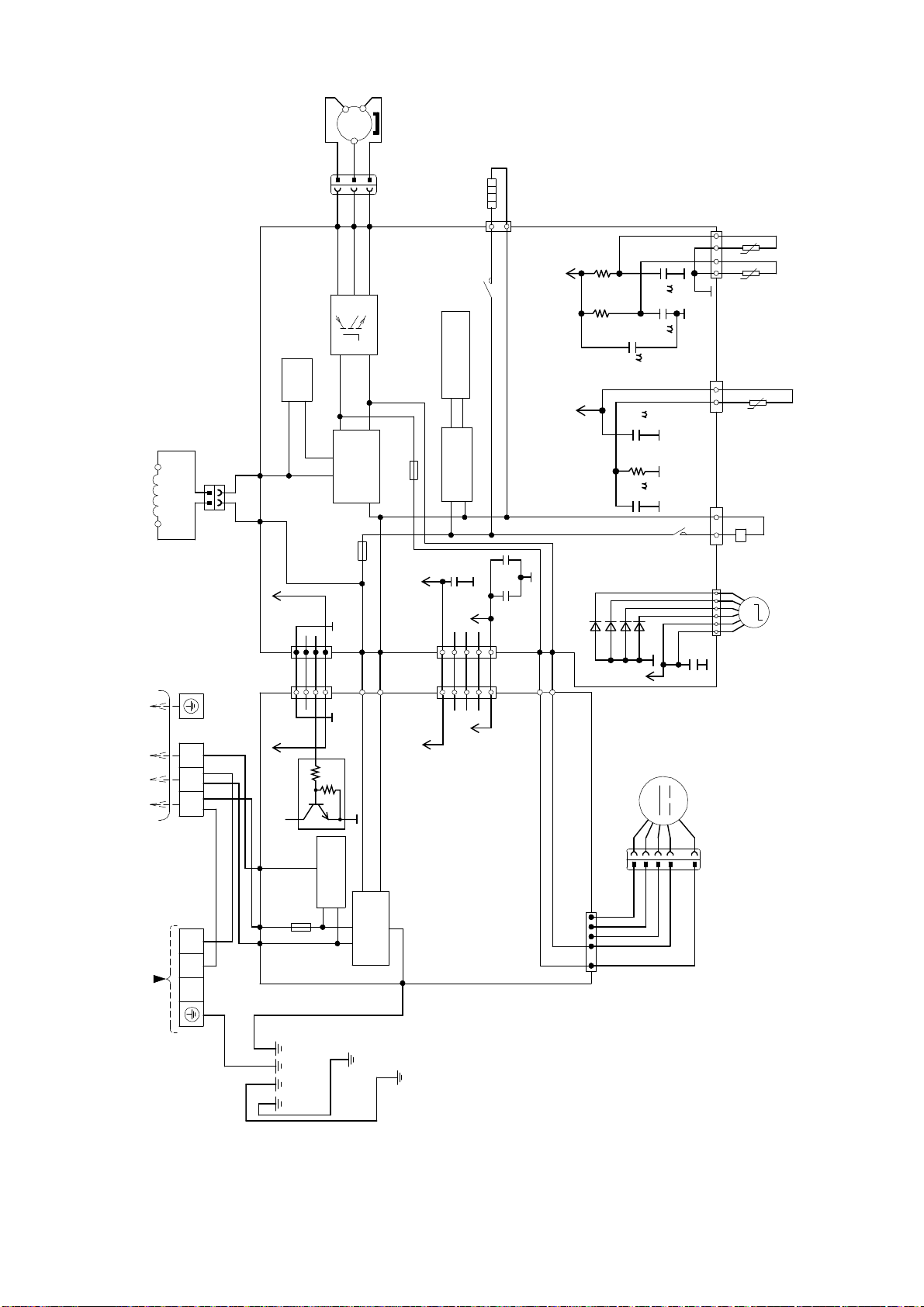
9. Electronic Circuit Diagram
TEMP
OFF/O
N
TIMER
S
CANCEL
O
N
OFF123
C
9.1 Indoor Unit
9.1.1 CS-E9RKUAW CS-E12RKUAW
TO
OUTDOOR
UNIT
TERMINAL
BOARD
1
2
3
TEMP.
FUSE
102°C
(3A)
GROUNDING
TERMINAL
Y/G
EVAPORATOR
FAN MOTOR
M
ELECTRONIC CONTROLLER
(DISPLAY & RECEIVER)
IC201
R213
R208
GND-A
45
JP201R210
JP200R211
JP203R212
JP204
BL
R
W
Y
B
W
BL
R
Vout
Vcc
GND
GNDGND
+
C201
47u
c
e
AC306 (BLK)
AC303 (WHT)
AC304 (RED)
G301 (GRN )
G
7
6
5
4
1
CN–FM (WHT)
R209
47
1
2
3
C202
0.01u
R218
0
SEN201
PCB3
LED205
2
POWERFUL/QUIET
(orange/green)
FUSE301
T3.15A L250V
ELECTRONIC
CONTROLLER
(MAIN)
5V_
(green)
(orange)
(green)
NANOE G/AUTO COM F
(green)
R207
620
3
1
R206
2.7k
NOISE FILTER
COMMUNICATION
CIRCUIT
RECTIFICATION
CN–DISP (YLW)
CN–DISP (WHT)
BZ201
POWER
LED201
TIMER
LED202
ECO NAVI
LED203
LED204
R216
0
R217
0
AUTO SW
(SW01)
CIRCUIT
CIRCUIT
R62
15.0k
5V
R89
1
WWWWWWWW W
11
BZ
R201 470
R202
2k
R203
27k
R204
820
Q201
10k
b
4.7k
Q202
10k
b
4.7k
5V_
e
c
5V_
e
c
C25
1u
*R74
*R75
*C41
20.0k
1
12V
R215
5V
*R54
*R37
270
10k
*C45
5V
0.1u
4
12V
VCC
9
16
1
IC03
15
2
IC03
14
3
IC03
13
4
IC03
12
5
IC03
11
6
IC03
R46R47
10
7
IC03
GND
8
C27
R61
*R63
1u
5V
C3
0.1u
12
*C49
NONE
12V
CN–RMT
(WHT)
CN–STM1
(WHT)
5V
CN–TH
(RED)
*C28
CN–MSENS
(WHT)
1
1
BR
1
R
O
Y
P
5
6
1
3
1
W
W
W
t
t
t
CN–MSENS
1
(WHT)
PIPING TEMP. SENSOR 2
(THERMISTOR)
PIPING TEMP. SENSOR 1
(THERMISTOR)
SUCTION TEMP. SENSOR
(THERMISTOR)
8
UP DOWN
M
LOUVER MOTOR
5
5V_3
ELECTRONIC CONTROLLER
(COMPARATOR)
R401
R402
5V_3
R403
C403
W
1
1
6
7
IC401
5
(WHT)
3
CN–SENS1
2
8
1
IC401
3
4
ELECTRONIC
W
W
CONTROLLER
SENS1
3
–
(YLW)
(ECO SENSOR)
CN
REMOTE CONTROLLER
HEAT
DRY
FAN
OFF/ON
ECONAVI
MODE
TEMP
POWERFUL/
FAN SP EED
QUIET
TIMER
ON
1
2
OFF
SET CHECK CLOCK RESET
HECK
AUTO
COMFORT
AIRSWING
CANCEL
AC
FAN
SPEED
AIR
SWING
SET
ET
3
RC
AUTO
COOL
0
24
Page 25
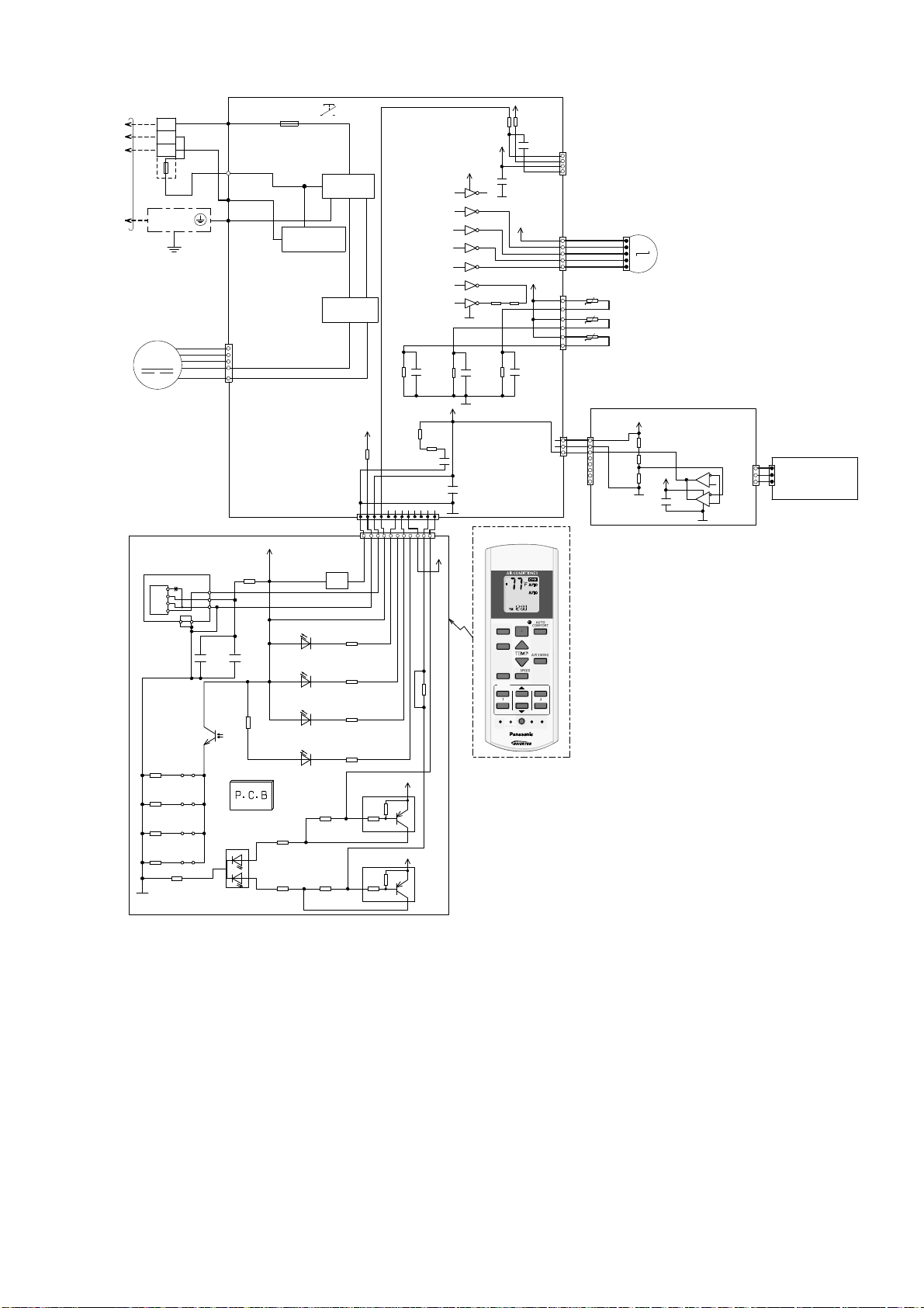
9.1.2 CS-E18RKUAW CS-E24RKUAW
TEMP
OFF/O
N
TIMER
S
CANCEL
O
N
O
123
C
TO
OUTDOOR
UNIT
TERMINAL
BOARD
1
2
3
TEMP.
FUSE
102°C
(3A)
GROUNDING
TERMINAL
Y/G
EVAPORATOR
FAN MOTOR
M
ELECTRONIC CONTROLLER
(DISPLAY & RECEIVER)
IC201
R213
R208
GND-A
45
JP201R210
JP200R211
JP203R212
JP204
BL
R
W
Y
B
W
BL
R
Vout
Vcc
GND
GNDGND
+
C201
47u
c
e
AC306 (B LK)
AC303 (WHT)
AC304 (RED)
G301 (GRN)
G
7
6
5
4
1
CN–FM (WHT)
R209
47
1
2
3
C202
0.01u
R218
0
SEN201
PCB3
LED205
2
POWERFUL/QUIET
(orange/gree n )
FUSE301
T3.15A L250V
ELECTRONIC
CONTROLLER
(MAIN)
5V_
(green)
(orange)
(green)
NANOE G/AUTO COMF
(green)
R207
620
3
1
R206
2.7k
COMMUNICATION
ECO NAVI
NOISE FILTER
CIRCUIT
RECTIFICATION
CN–DISP (YLW)
CN–DISP (WHT)
BZ201
POWER
LED201
TIMER
LED202
LED203
LED204
R216
0
R217
0
AUTO SW
(SW01)
CIRCUIT
CIRCUIT
R62
15.0k
5V
R89
1
WWWWWWWW W
11
BZ
R201 470
R202
2k
R203
27k
R204
820
Q201
10k
b
4.7k
Q202
10k
b
4.7k
C25
1u
*R74
*R75
*C41
5V_
e
c
5V_
e
c
1
12V
R215
R61
20.0k
12
0
12V
VCC
9
1
IC03
2
IC03
3
IC03
4
IC03
5
IC03
6
IC03
7
IC03
GND
8
C27
5V
C3
0.1u
5V
*R54
*R37
270
10k
5V
*C49
NONE
16
15
12V
14
13
12
11
R46R47
10
*C28
*R63
1u
REMOTE CONTROLLER
AUTO
HEAT
COOL
DRY
FAN
OFF/ON
ECONAVI
MODE
TEMP
POWERFUL/
FAN SPEED
QUIET
TIMER
ON
1
2
OFF
FF
SET CHECK CLOCK RESET
HECK
*C45
0.1u
CN–RMT
(WHT)
CN–STM1
(WHT)
5V
CN–TH
(RED)
CN–MSENS
(WHT)
FAN
SPEED
AIR
SWING
AUTO
COMFORT
AIRSWING
SET
ET
3
CANCEL
AC
RC
4
1
1
BR
1
R
O
Y
P
5
6
t
t
t
1
CN–MSENS
(WHT)
1
3
W
W
W
1
8
UP DOWN
M
LOUVER MOTOR
5
PIPING TEMP. SENSOR 2
(THERMISTOR)
PIPING TEMP. SENSOR 1
(THERMISTOR)
SUCTION TEMP. SENSOR
(THERMISTOR)
5V_3
ELECTRONIC CONTROLLER
(COMPARATOR)
R401
R402
5V_3
R403
C403
W
1
1
6
7
IC401
5
(WHT)
3
CN–SENS1
2
8
1
IC401
3
4
ELECTRONIC
W
W
CONTROLLER
SENS1
3
–
(YLW)
(ECO SENSOR)
CN
25
Page 26
9.2 Outdoor Unit
9.2.1 CU-E9RKUA CU-E12RKUA
ELECTRONIC-MAGNETIC
COIL (4-WAY VALVE)
AIR TEMP. SENSOR
CN-TH
R12
15.0k
5V
R11
C80
13V
123456
D26
D27
D28
D29
M
ELECTRONIC-MAGNETIC
COIL (EXPANSION VALVE)
CN-STM
t°t°t°
(THERMISTOR)
(WHT)
15.8k
1
234
C7
PFC
PIPING TEMP. SENSOR
(THERMISTOR)
COMPRESSOR TEMP. SENSOR
(THERMISTOR)
1
3
(WHT)
CN-TANK
1
C6
5V
1
CIRCUIT
CIRCUIT
RECTIFICATION
RAT1
(GRY)
T3.15A L250V
REACTOR
RAT2
(GRY)
FUSE 102
CIRCUIT
RECTIFICATION
YLW
YLW
1
3
(WHT)
CN-HOT
R1
4.99k
D19
C3
1
3~
MS
COMPRESSOR
BLU
YLW
RED
(BLU)
(YLW)
(RED)
V
U
W
Q1
P
N
ELECTRONIC CONTROLLER
FUSE 103
T3.15A l250v
CIRCUIT
SWITCHING
POWER SUPPLY
GRY GRY
13V
CIRCUIT
COMMUNICATION
TERMINAL BOARD
DATA (RED)
3
(RED)
WHT RED
2
TO INDOOR UNITPOWER SUPPLY
(BLACK)
1
(BLACK)
WHT
BLK
BLK
L1 L2
GRN
CIRCUIT
NOISE FILTER
CN-HT1
12345
RY-HT1
CN-HT2
12345
RY-HT2
CN-DCFM
FUSE 101
20A 250V
AC-BLK
(BLK)
AC-WHT
(WHT)
GRN
FG1 (GRN)
14567
LJP101 (GRN)
GRN
HT2 (ORG)
1
234
12345
CN4
(BLK)
5V
M
FAN
MOTOR
R1291kR118
5V
ELECTRONIC
CONTROLLER
R1301kR116
9
CN5
(BLK)
13_1V
16151413121110
IC12
IC12
IC12
IC12
IC12
1234567
IC12
5
RY-HT2
8
IC12
ACL (BRW)BRW
ACL (BRW)
HT2 (ORG)
ORG
HEATER
ORG
26
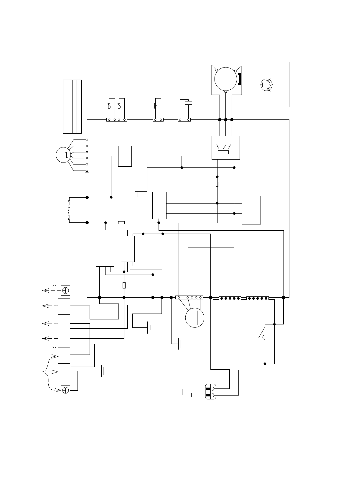
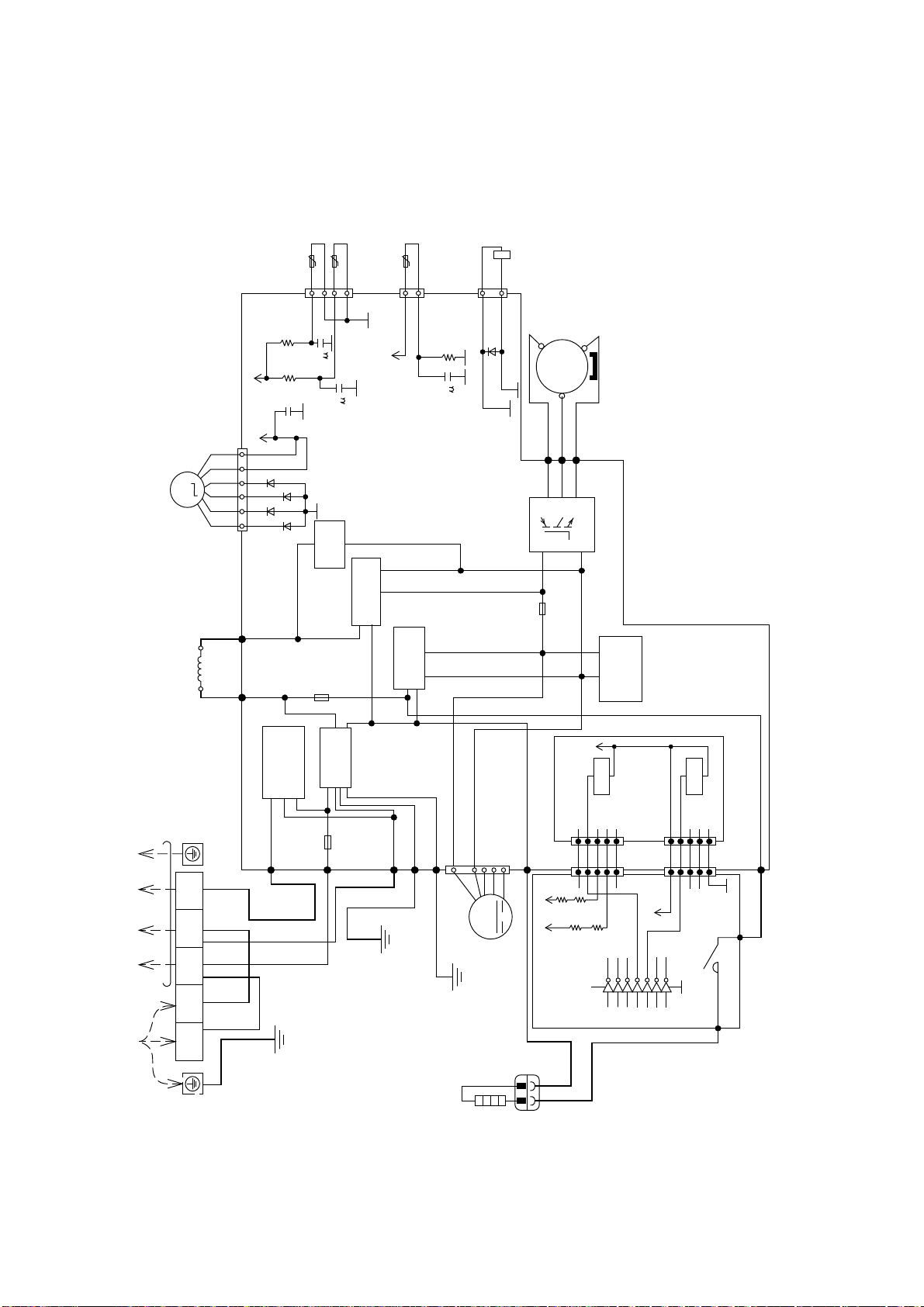
Page 27
9.2.2 CU-E18RKUA CU-E24RKUA
SEN
S
O
R(T
R
MISTOR)
REACTOR
~
3
MS
COMPRESSOR
BLU
YLW
RED
3
3
RED
(RED) U
Q10
PFC
CIRCUIT
ELECTRONIC CONTROLLER (MAIN)
BLK
L2-0
(BLACK)
BLK
1
1
2
2
L2-1
GRY
GRY
TO INDOOR UNIT
123
TERMINAL
BOARD
BLK
WHT
TERMINAL
BOARD
(GRAY)
5V5V
123
CN-COM
CN-COM
RED
COM3
BLK
ACL1
4
(YELLOW)
WHT
WHT
WHT
WHT
123
4
(YELLOW)
b
4.7k
10k
Q25
c
(RED)
COMMUNICATION
FUSE3
(25A, 250V)
(BLACK)
L2
L1
ACN1
(WHITE)
1
1
BLU
YLW
(BLUE) V
(YELLOW) W
V
U
W
P
N
CIRCUIT
FUSE1
RECTIFIC ATION
FUSE2
(T 3.15A L 250V)
AC-BLK
(BLACK)
AC-WHT
BLK
WHT
CN-BLK
(BLACK)
CN-WHT
e
CIRCUIT
CIRCUIT
NOISE F ILTER
(T 2.5A L 250V)
(WHITE)
(WHITE)
5V
CN-FM1
CN-FM1
5V
FG1
12345
(WHITE)
WHT
123
(WHITE)
(GREEN)
HEATER
OUTDOOR AIR
TEMP. SENSOR
(THERMISTOR)
t° t°
(WHITE)
PIPING TEMP.
SENSOR
(THERMISTOR)
HE
t°
(WHITE)
(BLUE)
BLU
M
(WHITE)
DISCHARGE TEMP.
ELECTRO-MAGNETIC
COIL (4-WAY VALVE)
COIL
(EXPANSION VALVE)
ELECTRO-MAGNETIC
1
C45
1
C46
BLK
RY-HOT
*C84
44
11
RED
1234
CN-TH1
1
2
CN-DIS
CN-HOT
3
1
123456
CN-EV
1
3
CN-HT
(BLACK)
RY-HT
SUPPLY CIRCUIT
SWITCHING POWER
CIRCUIT
RECTIFIC ATION
C260
+
C209
WHT
15V_2
WHT
15V_2
ELECTRONIC CONTROLLER
C259
WHT
WHT
5
4
(NOISE F ILTER)
DC-FM1
DC-FM1
(ORANGE)
ORG
(ORANGE)
V
5
DC-FMG
YLW
DC-FMG
R100
15.0k
R101
15.8k
C251
220
5V
(YELLOW)
*D36
(YELLOW)
(WHITE)
CN-DCFM
7
4
1
1
C212
R102
4.99k
1
C47
*D35
*D34
*D33
13V
M
FAN M OTO R
7
7
BLU
YLW
WHT
POWER SUPPLY
GRN WHT
YLW/GRN
GRN
YLW/GRN
27
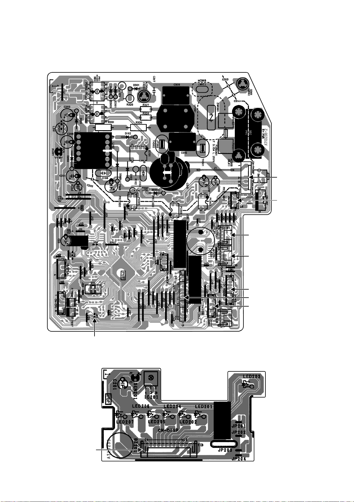
Page 28
10. Printed Circuit Board
JP1(Ran
dom
R
e
e
nable/d
e
)
10.1 Indoor Unit
10.1.1 Main Printed Circuit Board
CN-FM
CN-RMT
Auto
start
isabl
10.1.2 Indicator Printed Circuit Board
CN-STM2
(E18/24RKUAW only)
CN-STM1
CN-MSENS
CN-DISP
CN-TH
CN-DISP
28
Page 29
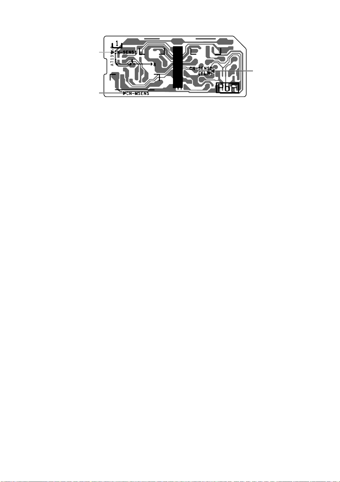
10.1.3 Comparator Printed Circuit Board
CN-SENS1
CN-SENS2
CN-MSENS
29
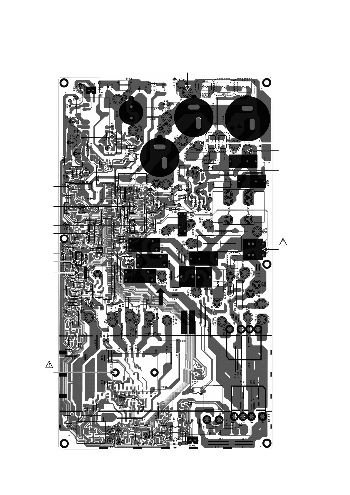
Page 30
10.2 Outdoor Unit
10.2.1 Main Printed Circuit Board
10.2.1.1 CU-E9RKUA CU-E12RKUA
CN-DCFM
FG1
AC-BLK
AC-WHT
DATA
CN5
CN4
CN-STM
CN-TANK
CN-TH
CN-HOT
POWER
TRANSISTOR
(IPM)
CURRENT
TRANSFORMER
(CT)
30
Page 31

10.2.1.2 CU-E18RKUA CU-E24RKUA
D
C-FM
G
CN-TH1
CN-EV
CN-DIS
CN-HT
CN-S
CN-COM
CN-FM1
CN-HOT
AC-BLK
AC-WHT
CURRENT
TRANSFORMER
(CT)
DC-FM1
POWER
TRANSISTOR
(IPM)
31
Page 32

10.2.2 Noise Filter Printed Circuit Board
10.2.2.1 CU-E18RKUA CU-E24RKUA
32
Page 33

11. Installation Instruction (E9RK and E12RK)
11.1 Select the Best Location
11.1.1 Indoor Unit
Do not install the unit in excessive oil fume area
such as kitchen, workshop and etc.
There should not be any heat source or steam
near the unit.
There should not be any obstacles blocking the air
circulation.
A place where air circulation in the room is good.
A place where drainage can be easily done.
A place where noise prevention is taken into
consideration.
Do not install the unit near the door way.
Ensure the spaces indicated by arrows from the
wall, ceiling, fence or other obstacles.
Recommended installation height for indoor unit
shall be at least 8 ft (2.4 m).
11.1.2 Outdoor Unit
If an awning is built over the unit to prevent direct
sunlight or rain, be careful that heat radiation from
the condenser is not obstructed.
There should not be any animal or plant which
could be affected by hot air discharged.
Keep the spaces indicated by arrows from wall,
ceiling, fence or other obstacles.
Do not place any obstacles which may cause a
short circuit of the discharged air.
If piping length is over the [piping length for
additional gas], additional refrigerant should be
added as shown in the table.
Recommended installation height for outdoor unit
should be above the seasonal snow level.
Capacity
Model
(Btu/h)
E9RKUAW 9000
E12RKUAW 11500
Piping size
Gas
3/8"
(9.52 mm)
1/2"
(12.7 mm)
Liquid
1/4"
(6.35 mm)
Std.
Length
24.6 ft
(7.5 m)
Max.
Elevation
49.2 ft
(15 m)
Min.
Piping
Length
9.8 ft
(3 m)
Max.
Piping
Length
65.6 ft
(20 m)
Refrigerant
Example: For E9RKUAW
If the unit is installed at 32.8 ft (10 m) distance, the
quantity of additional refrigerant should be 1.64 oz
(50 g) .... (32.8 - 24.6) ft x 0.2 oz/ft = 1.64 oz.
((10 -7.5) m x 20 g/m = 50 g).
Additional
0.2 oz/ft
(20 g/m)
Piping
Length
for add.
gas
24.6 ft
(7.5 m)
11.1.3 Indoor/Outdoor Unit Installation
Diagram
Piping direction Do not bend up
Right
Rear
Right
bottom
31
1
/
32
"
(50 mm)
or more
Insulation of piping connections
• Carry out insulation after
checking for gas leaks and
secure with vinyl tape.
Attaching the remote control holder to the wall
Remote control holder fixing screws
Remote
3
control
It is advisable to
avoid more than 2
blockage directions.
For better ventilation
& multiple-outdoor
installation, please
consult authorized
dealer/specialist.
•
This illustration is for
explanation pur poses only.
The indoor unit will actually face
a different way.
(Front side)
Left
Rear
Left
Left bottom
(Left and right are identical)
Floor / Grade level
Vinyl tape
Remote control holder
drain hose
6
3
1
(
1
0
0
o
r
m
o
Installation parts you
"
)
6
1
m
/
e
m
r
o
0
0
m
r
o
1
1
(
3
0
0
o
r
m
o
should purchase ()
Installation plate 1
Bushing-Sleeve (
Sleeve (
Putty (
)
(Gum Type Sealer)
Bendthepipeas
closely on the wall as
possible, but be careful
that it doesn’t break.
Vinyl tape (wide) ()
• Apply after carr ying
out a drainage test.
• To carry out the
drainage test,
remove the air filters
and pour water into
the heat exchanger.
Saddle (
Conduit
(Power supply cord (
Conduit
(Connection cable)
Liquidsidepiping(
Gas side piping (
Additional drain hose (
Control Board cover
1
3
/
1
6
m
"
m
)
r
e
)
)
)
))
)
)
)
)
e
"
r
m
6
o
1
m
/
m
9
5
r
6
2
o
(
)
m
e
r
4
o
.
2
m
(
r
t
f
o
8
5
5
5
/
1
6
"
m
m
)
r
e
"
8
/
3
m
9
3
0
0
0
m
1
r
(
o
1
3
(1
)
m
e
r
o
33
Page 34

11.2 Indoor Unit
M
11.2.1 How to Fix Installation Plate
The mounting wall shall be strong and solid enough to prevent it from the vibration.
easuring
Ta pe
Wall
917/32"
(241.5 mm)
51/16"
(128 mm)
More than 1
Indoor unit
2 screw
3 4
6
5
5
For best strength of
INDOOR unit installation,
it is highly recommended
to locate “
as shown.
More than
1
/16" (128 mm)
Installation plate 1
” at 5 position
Wall
More than 1
2
917/32"
(241.5 mm)
51/16"
(128 m m )
Wall
Dimension
179/32"
(439 mm)
17"
(432 mm)
111/16"
(43 mm)
E9RKUAW,
E12RKUAW
Model
123 456
or
199/32"
(490 mm)
37/32"
(82 mm)
The center of installation plate should be at more than at right and left of the wall.
The distance from installation plate edge to ceiling should more than .
From installation plate left edge to unit’s left side is .
From installation plate right edge to unit’s right side is .
B : For left side piping, piping connection for liquid should be about from this line.
○
: For left side piping, piping connection for gas should be about from this line.
1 Mount the installation plate on the wall with 5 screws or more (at least 5 screws).
(If mounting the unit on the concrete wall, consider using anchor bolts.)
o Always mount the installation plate horizontally by aligning the marking-off line with the thread and using
a level gauge.
2 Drill the piping plate hole with ø2 3/4" (ø70 mm) hole-core drill.
o Line according to the left and right side of the installation plate. The meeting point of the extended line is
the center of the hole. Another method is by putting measuring tape at position as shown in the diagram
above. The hole center is obtained by measuring the distance namely 5 1/16" (128 mm) for left and right
hole respectively.
o Drill the piping hole at either the right or the left and the hole should be slightly slanting to the outdoor
side.
11.2.2 To Drill a Hole in the Wall and
Install a Sleeve of Piping
1 Insert the piping sleeve to the hole.
2 Fix the bushing to the sleeve.
Wall
Indoor
3 Cut the sleeve until it extrudes about 19/32"
(15 mm) from the wall.
CAUTION
When the wall is hollow, please be sure
to use the sleeve for tube assembly to
prevent dangers caused by mice biting
the connection cable.
Sleeve for
tube
assembly
4 Finish by sealing the sleeve with putty or
caulking compound at the final stage.
3
/4" (ø70 mm)
ø2
through hole
33/4"
(95 mm)
Outdoor
19
/32" (15 mm)
Bushing for tube
assembly
Putty or caulking compound
Approx.
7
/32" -9/32"
(5-7 mm)
34
Page 35

11.2.3 Indoor Unit Installation
Do not tur n over the unit without it’s shock absorber during pul l out the piping.
It may cause intake grille damage.
Use shock absorber during pull out the piping to protect the intake gr ille from damage.
p
u
l
l
o
u
t
t
h
e
p
i
p
i
n
g
Piping
Piping
p
u
l
l
o
u
t
t
h
e
p
i
p
i
n
g
PUSH PUSH
Intake grille
11.2.3.1 For the right rear piping
Step-1
Step-2
Step-3
Step-4
Pull out the Indoor piping
Install the Indoor Unit
Secure the Indoor Unit
Insert the connection cable
11.2.3.2 For the right bottom piping
Step-1
Step-2
Step-3
Step-4
Pull out the Indoor piping
Install the Indoor Unit
Insert the connection cable
Secure the Indoor Unit
11.2.3.3 For the embedded piping
Step-1
Step-2
Step-3
Step-4
Step-5
Step-6
Step-7
Step-8
Replace the drain hose
Bend the embedded piping
• Use a spring bender or equivalent to bend the
piping so that the piping is not crushed.
Pull the connection cable into Indoor Unit
• The inside and outside connection cable can be
connected w ithout removing the front grille.
Cut and flare the embedded piping
• When determining the dimensions of the p iping,
slide the unit all the way to the left on the installation
plate.
• Refer to the section “Cutting and flaring the piping”.
Install the Indoor Unit
Connect the piping
• Please refer to “Connecting the piping” column in
outdoor unit section. (Below steps are done after
connecting the outdoor piping and gas-leakage
confirmation.)
Insulate and finish the piping
• Please refer to “Insulation of piping connection”
column as mentioned in indoor/outdoor unit
installation.
Secure the Indoor Unit
PUSH PUSH
Shock absorber
Right Rear piping
Tap e i t wi t h
piping in a posi tion as
mentioned in
Fig. below.
Piping
Drain
hose
Cover for the
bottom piping
Cover for the
bottom piping
Cover
for the
left
piping
Cover for the
bottom piping
Unit’s
hook
Cover for pipi ng
Hooks at
installation
plate
Sleeve f or
piping hole
Drain hose
Installation
plate
Gas side
piping
Liquid side
piping
Drain hose
Cover for
the left
piping
Piping
How to keep the cover
In case of the cover is cut, keep the
cover at the rear of chassis as shown
in the illustration for future
reinstallation.
(Left and 2 bottom covers for piping.)
Right and Right Bottom piping
Tape it with piping in a
position as menti oned
in Fig. below.
Drain hose
Piping
Cover for
the r ight
piping
Install the indoor unit
Hook the indoor unit onto the upper
portion of installation plate. (Engage
the indoor unit with the upper edge
of the installation plate). Ensure the
hooks are properly seated on the
installation plate by moving it in left
and right.
Indoor unit
Secure the Indoor Unit
1. Press the lower left and right side
of the unit against the installation
plate until hooks engages with their
slot (sound click).
To take out the unit, push the
marking at the bottom unit, and pull it
slightly towards you to disengage the
k
m
r
a
g
n
i
hooks from the unit.
Insert the connection cable
A
2
b
3
o
/
(
4
u
7
"
t
0
-
-
3
8
5
0mm
/
3
2
"
)
Guide
surface
Connection
cable
Connection cable
(This can be used for left rear piping and bottom
piping also.)
35
Page 36

Replace the drain hose
Rear view for left piping installation
Drain cap
How to pull the piping and drain hose out, in case of embedded piping.
•
Drain hose
Apply putty or
caulking material
to seal the wa ll
opening.
PVC tube for
drain hose (VP-20)
PVC tube
for d rain
hose
M
3
"
16
/
9
18
PVC tube (VP-65) for piping
More than 27
(700 mm)
and connection cable
PVC tube for drain hose (VP-30)
Indoor unit
15
/16"(100mm)
3
Connection
cable
Adjust the piping slightly downwards.
)
m
m
n
a
0
h
5
t
9
(
e
r
"
2
o
3
/
3
1
7
Connection
cable
Piping
n
a
h
t
e
r
M
1/2
o
"
Cable
Piping
(
4
0
7
)
m
m
Drain hose
from main unit
Drain hose
Connection
°
5
4
cable
More than 37
(950 mm)
Cable
13
/32"
Piping
Drain hose
Sleeve for pip ing hole
How to insert the connection cable and drain hose
•
inthecaseofleftpiping.
Drain
hose
Piping
(For right piping, follow the same procedure)
Drain hose adapter
Join indoor drain hose to 3/4" (20 mm) nominal PVC pipe size
•
by using drain hose adapter
Remarks :
Make sure indoor unit drain hose & 3/4" (20 mm ) nom inal PVC pipe
are fully inserted to drain hose adapter
9
usage
when necessary.
9
9
.
11.2.4 Connect the Cable to the Indoor Unit
1. The inside and outside connection cable can
be connected without removing the front grille.
2. Unscrew the conduit cover and fix the conduit
connector to conduit cover with lock nut, then
secure it against chassis.
3. Connection cable between indoor unit and
outdoor unit should be UL listed or CSA
approved 4 conductor wires minimum AWG16
in accordance with local electric codes.
4. Connection cable between indoor unit and
outdoor unit should be UL listed or CSA
approved 4 conductor wires minimum AWG16
in accordance with local electric codes.
o Ensure the colour of wires of outdoor unit
and terminal number are the same as the
indoor's repectively.
Terminals on the indoor unit 1 2 3
Colour of wires (connection cable)
Terminals on the outdoor unit 1 2 3
WARNING
This equipment must be properly ear thed.
Indoor unit
drain hose
Close join by Vinyl Tape ( )
Drain hose adapter
3/4" (20 mm) nominal PVC pipe
- Install incline downward more than 1 °
- Apply PVC glue at the join.
9
o Earth lead wire shall be Yellow/Green
(Y/G) in colour and shall be longer than
other lead wires as shown in the figure for
electrical safety in case of the slipping.
Conduit
Connector
Conduit
Cover
Lock Nut
Chassis
Rear Side of Indoor Unit
Ter m i na l
Board
Indoor and
outdoor
connection
cable
123
Holder
Earth Wire
longer than
others AC
wires for
safety
reason
36
Page 37

11.2.5 Wiring Stripping and connecting requirement
mproperfla
rin
g
Wire stri pping
Indoor/outdoor
connection
terminal board
No loose strand
when inserted
WARNING
Do not joint wires
(10±1 mm)
13/32" ± 1/16"
RISK OF FIRE
JOINING OF WIRES
MAY CAUSE
OVER HEATING
AND FIRE.
7
/32"
(5 mm)
or more
(gap between wires)
Conductor
fully inserted
ACCEPT PROHIBITED PROHIBITED
Conductor
over inserted
OR
Conductor not
fully inserted
OR
OR
Use complete wire without joining.
Use approved socket and plug with earth pin.
Wire connection in this area must follow to
national wiring rules.
11.2.5.1 Cutting and flaring the piping
1 Please cut using pipe cutter and then remove the burrs.
2 Remove the burrs by using reamer. If burrs are not removed, gas leakage may be caused. Turn the piping
end down to avoid the metal powder entering the pipe.
3 Please make flare after inserting the flare nut onto the copper pipes.
1
Bar
0–
/32"
(0-0.5 mm)
Copper
pipe
When properly flared, the internal surface of the
flare will evenly shine and be of even thickness.
Since the flare part comes into contact with the
connections, carefully check the flare finish.
.Tocut
Pipe
Point down
2. To remove burrs
Reamer
Bar
Clamp handle
3. To flare
Handle
Yo ke
Core
Red arrow mark
I
Inclined Surface
damaged
Cracked U n even
thickness
37
Page 38

11.3 Outdoor Unit
S
11.3.1 Install the Outdoor Unit
After selecting the best location, start installation according to indoor/outdoor unit installation diagram.
1 Fix the unit on concrete or rigid frame firmly and horizontally by bolt nut (ø13/32" (ø10 mm)).
2 When installing at roof, please consider strong wind and earthquake.
Please fasten the installation stand firmly with bolt or nails.
11.3.2 Connect the Piping
11.3.2.1 Connecting the piping to
indoor
Please make flare after inserting flare nut (locate at
joint portion, of tube assembly) onto the copper pipe.
(In case of using long piping)
Connect the piping
Align the center of piping and sufficiently tighten
the flare nut with fingers.
Further tighten the flare nut with torque wrench in
specified torque as stated in the table.
11.3.2.2 Connecting the piping to
outdoor
Decide piping length and then cut by using pipe cutter.
Remove burrs from cut edge.
Make flare after inserting the flare nut (locate at valve)
onto the copper pipe.
Align center of piping to valves and then tighten with
torque wrench to the specified torque as stated in the
table.
AB
C
D
Model A B C D
E9RKUA, E12RKUA
22-7/16"
(570 mm)
4-1/8"
(105 mm)
23/32"
(18.5 mm)
Do not over tighten, over tightening may cause gas leakage.
Piping size Torque
1/4" (6.35 mm) 13.3 Ibf.ft [18 N•m (1.8 kgf•m)]
3/8” (9.52 mm) 31.0 Ibf.ft [42 N•m (4.3 kgf•m)]
1/2" (12.7 mm) 40.6 Ibf.ft [55 N•m (5.6 kgf•m)]
5/8” (15.88 mm) 47.9 Ibf.ft [65 N•m (6.6 kgf•m)]
3/4" (19.05 mm) 73.8 Ibf.ft [100 N•m (10.2 kgf•m)]
panner
or Wrench
Torq u e
wrench
12-19/32"
(320 mm)
38
Page 39

11.3.2.3 Connecting the piping to outdoor multi
Decide piping length and then cut by using pipe cutter. Remove burrs from cut edge.
Make flare after inserting the flare nut (locate at valve) onto the copper pipe.
Align center of piping to valve and then tighten with torque wrench to the specified torque as stated in the table.
Male side Female side
(Adjustable Wrench)
Male side
(Adjustable Wrench)
Torque Wrench for Flare
Nut and Pipe Size Reducer
Hall Union
(Auxiliary pipe)
Wrench
(Auxiliary pipe)
Wrench
Hall Union
Pack ing
Flare Nut
(Connection pipe)
T orque Wrench for Flare Nut
Pipe Size
Reducer
Applicable to
Liquid and Gas side of
CS-E9RKUAW
Liquid side of
CS-E12RKUAW
Flare Nut
Female side
(Connection pipe)
Applicable to
Gas side of
CS-E12RKUAW
11.3.2.4 Gas Leak Checking
Pressure test to system to 400 PSIG with dry nitrogen, in stages. Thoroughly leak check the system.
If the pressure holds, release the nitrogen and proceed to section 11.3.3.
11.3.3 Evacuation of the equipment
WHEN INSTALLING AN AIR CONDITIONER, BE SURE TO EVACUATE THE AIR INSIDE THE INDOOR UNIT AND
PIPES in the following procedures.
Indoor unit
OPEN
Vacuum
pump
1. Connect a charging hose with a push pin to the Low side of a charging set and the service port of the 3-way
valve.
2. Connect the micron gauge between vacuum pump and service port of outdoor units.
3. Turn on the power switch of the vacuum pump and make sure that connect digital micron gauge and to pull
down to a value of 500 microns.
4. To make sure micron gauge a value 500 microns and close the low side valve of the charging set and turn off
the vacuum pump.
5. Disconnect the vacuum pump house from the service port of the 3-way valve.
6. Tighten the service port caps of the 3-way valve at a torque of 13.3 Ibf.ft (18 N•m) with a torque wrench.
7. Remove the valve caps of both of the 2-way valve and 3-way valve. Position both of the valves to “Open”
using a hexagonal wrench (5/32" (4 mm)).
8. Mount valve caps onto the 2-way valve and the 3-way valve.
o Be sure to check for gas leakage.
If micron gauge value does not descend 500 microns, take the following measures:
•
- If the leak stops when the piping connections are tightened further, continue working from step3.
- If the leak does not stop when the connections are retightened, repair location of leak.
- Do not release refrigerant during piping work for installation and reinstallation.
- Be careful with the liquid refrigerant, it may cause frostbite.
Liquid side
Hi
Lo
Gas side
CLOSE
Two-way valve
Close
Three-way valve
Close
Outdoor unit
39
Page 40

11.3.3.1 Connect the Cable to the Outdoor Unit
o
pPa
n
C
C
r
U
r
U
1. Remove Top panel.
2. Remove Control Board Cover (Resin and
Metal).
3. Remove Plugs.
4. Fix the conduit connectors to the knockout
holes with lock-nuts, then secure them against
the side panel.
5. All wires pass through conduits.
6. Connection cable between indoor unit and
outdoor unit should be UL listed or CSA
approved 4 conductor wires minimum AWG16
in accordance with local electric codes.
7. Wire connection to the power supply
(208/230V 60Hz) through circuit breaker.
o Connect the UL listed or CSA approved
wires minimum AWG14 to the terminal
board, and connect the other end of the
wires to ELCB / GFCI.
8. Connect the power supply cord and
connection cable between indoor unit and
outdoor unit according to the diagram below.
9. Secure the wire onto the control board with
the holder (clamper).
10. After completing wiring connections, reattach
the control board cover (Metal and Resin) and
the top panel to the original position with the
screws.
11. For wire stripping and connection requirement,
refer to instruction 11.2.5 of indoor unit.
This equipment must be properly ear thed.
Earth lead wire shall be Yellow/Green (Y/G) in
colour and shall be longer than other lead wires
as shown in the figure for electrical safety in case
of the slipping.
Indoo
nit
1
2
3
WARNING
208/230V min AWG16
208/230V min AWG16
208/230V min AWG16
Grounding wire min AWG16
* Ensure all connecting wire
between indoor unit and
outdoor unit and power supply
cord are installed in individual
conduit.
Outdoo
1
2
3
L1
L2
ontrol Board
over (Resin)
nit
lanimreTlanimreT
Disconnect
Switch
Field supply
Grounding wire
Earth wire
longer than
others AC
wires for
safety
reason
Control Board
Metal Cover
Connectors
Power Supply
Single Phase
208/230V 60Hz
min AWG14
L1 L2 1 2 3
Power
supply
cord
T
Indoor &
outdoor
connection
cable
el
Power
Supply
Wires
Lock Nuts
Knockout
Holes
Plugs
Side Panel
Ter m i na l
Board
Earth wire
longer than
others AC
wires for
safety
reason
Holder
11.3.3.2 Piping Insulation
1. Please carry out insulation at pipe connection portion as mentioned in Indoor/Outdoor Unit Installation
Diagram. Please wrap the insulated piping end to prevent water from going inside the piping.
2. If drain hose or connecting piping is in the room (where dew may form), please increase the insulation by
using POLY-E FOAM with thickness 1/4" (6 mm) or above.
40
Page 41

12. Installation Instruction (E18RK and E24RK)
ferentway
12.1 Select the Best Location
12.1.1 Indoor Unit
Do not install the unit in excessive oil fume area
such as kitchen, workshop and etc.
There should not be any heat source or steam
near the unit.
There should not be any obstacles blocking the air
circulation.
A place where air circulation in the room is good.
A place where drainage can be easily done.
A place where noise prevention is taken into
consideration.
Do not install the unit near the door way.
Ensure the spaces indicated by arrows from the
wall, ceiling, fence or other obstacles.
Recommended installation height for indoor unit
shall be at least 8 ft (2.4 m).
12.1.2 Outdoor Unit
If an awning is built over the unit to prevent direct
sunlight or rain, be careful that heat radiation from
the condenser is not obstructed.
There should not be any animal or plant which
could be affected by hot air discharged.
Keep the spaces indicated by arrows from wall,
ceiling, fence or other obstacles.
Do not place any obstacles which may cause a
short circuit of the discharged air.
If piping length is over the [piping length for
additional gas], additional refrigerant should be
added as shown in the table.
Recommended installation height for outdoor unit
should be above the seasonal snow level.
Model
E18RKUA
E24RKUA
Capacity
(Btu/h)
17200
24000
Piping size
Gas Liquid
1/2"
12.7 mm)
(
5/8"
15.88 mm)
(
1/4"
(
6.35 mm)
Std.
Length
24.6 ft
(
7.5 m)
Max.
Elevation
49.2 ft
(
15 m)
Min.
Piping
Length
9.8 ft
(
3m)
Max.
Piping
Length
100.0 ft
(
30.5 m)
Example: For E18RKUA
If the unit is installed at 41 ft (12.5 m) distance, the
quantity of additional refrigerant should be 2.46 oz
(62.5 g) .... (41 - 32.8) ft x 0.3 oz/ft = 2.46 oz.
((12.5 - 10) m x 25 g/m = 62.5 g).
Additional
Refrigerant
0.3 oz/ft
(
25 g/m)
Piping
Length
for add.
gas
32.8 ft
(
10 m)
12.1.3 Indoor/Outdoor Unit Installation
Diagram
Piping di rection Attention not to bend
Right
Rear
Right
Left
Rear
bottom
131/32"
(50 mm)
or more
Insulation of pipi ng connections
• Carr y out insulation after
checking for gas leaks and
secure w ith vinyl tape.
Attaching the remote control holder to the wall
Remote control holder fixing screws
Remote
control
Left bottom
(Left and right are identical)
Floor / Grade level
3
Remote control holder
It is advisable to
avoid more than 2
blockage directions.
For better ventilation
& multiple-outdoor
installation, please
consult authorized
dealer/specialist.
• This i llustration is for
explanation pur poses only.
The indoor unit will actually face
adif
up drain hose(Front side)
Left
"
)
6
1
m
/
e
5
r
m
o
0
m
0
r
1
(
o
(
3
0
o
r
mo
Installation parts you
should purchase ()
Installation plate 1
Bushing-Sleeve (
Sleeve (
Putty (
(Gum Type Sealer)
Bend th e pipe as
closely on the wall as
possible, but be careful
that it doesn’t break.
Vinyl tape (wide) ()
• Apply after carrying
out a drainage test.
• To carry out the
drainage tes t,
remove the air filters
and pour water into
the heat exchanger.
Saddle (
Conduit
(Power supply cord (
Conduit
(Connection cable)
Liquid si de piping (
Gas side piping (
Additional drain ho se
1
Control Board cover
1
1
3
/
0mm)
1
6
"
r
e
)
)
)
)
))
)
)
)
e
"
r
m
6
o
1
/
m
9
m
5
r
2
6
o
(
)
m
e
r
4
o
.
2
m
(
r
t
f
o
8
Vinyl tape
6
5
3
1
(
5
1
/
0
1
0
6
"
o
m
r
m
m
o
)
r
e
"
8
/
3
m
m
9
r
3
0
o
0
0
m
1
r
(
o
.
1
3
)
e
41
Page 42

12.2 Indoor Unit
12.2.1 How to Fix Installation Plate
The mounting wall shall be strong and solid enough to prevent it from the vibration.
Wall
More than 1
Indoor unit
2 screw
3 4
Wall
More than
2
More than 1
Wall
51/16" (128 mm)
Installation plate 1
For best strength of
INDOOR unit installation,
it is highly recommended
to locate “
as shown.
37/32"
(82 mm)
” at 5 position
217/32"
(539 mm)
Dimension
2015/16"
(532 mm)
621/32"
(169 mm)
Measuring
Ta pe
E18RKUA, E24RKUA
917/32"
(241.5 mm)
Model
51/16"
(128 mm)
6
5
123 4 56
7
/32"
23
(590 mm)
The center of installation plate should be at more than at right and left of the wall.
The distance from installation plate edge to ceiling should more than .
From installation plate left edge to unit’s left side is .
From installation plate right edge to unit’s right side is .
B : For left side piping, piping connection for liquid should be about from this line.
○
: For left side piping, piping connection for gas should be about from this line.
1 Mount the installation plate on the wall with 5 screws or more (at least 5 screws).
(If mounting the unit on the concrete wall, consider using anchor bolts.)
o Always mount the installation plate horizontally by aligning the marking-off line with the thread and using
a level gauge.
2 Drill the piping plate hole with ø2 3/4" (ø70 mm) hole-core drill.
o Line according to the left and right side of the installation plate. The meeting point of the extended line is
the center of the hole. Another method is by putting measuring tape at position as shown in the diagram
above. The hole center is obtained by measuring the distance namely 5 1/16" (128 mm) for left and right
hole respectively.
o Drill the piping hole at either the right or the left and the hole should be slightly slanting to the outdoor
side.
12.2.2 To Drill a Hole in the Wall and
Install a Sleeve of Piping
1 Insert the piping sleeve to the hole.
2 Fix the bushing to the sleeve.
Wall
Indoor
3 Cut the sleeve until it extrudes about 19/32"
(15 mm) from the wall.
CAUTION
When the wall is hollow, please be sure
to use the sleeve for tube assembly to
prevent dangers caused by mice biting
the connection cable.
Sleeve for
tube
assembly
4 Finish by sealing the sleeve with putty or
caulking compound at the final stage.
3
ø2
/4" (ø70 mm)
through hole
17
/32”
9
(241.5 mm)
1
/16"
5
(128 mm)
85/8"
(219 mm)
Outdoor
19
/32" (15 mm)
Bushing for tube
assembly
Putty or caulking compound
Approx.7/32"-9/32"
(5 - 7 mm)
42
Page 43

12.2.3 Indoor Unit Installation
Do n ot tur n over the unit without it’s shock absorber during pull out the piping.
It may cause intake grille damage.
Use shock absorber during pull out the piping to protect the intake grille from damage.
p
u
l
l
o
u
t
t
h
e
p
i
p
i
n
g
Piping
Piping
p
u
l
l
o
u
t
t
h
e
p
i
p
i
n
g
PUSH PUSH
Intake grille
12.2.3.1 For the right rear piping
Step-1
Step-2
Step-3
Step-4
Pull out the Indoor piping
Install the Indoor Unit
Secure the Indoor Unit
Insert the connection cable
12.2.3.2 For the right bottom piping
Step-1
Step-2
Step-3
Step-4
Pull out the Indoor piping
Install the Indoor Unit
Insert the connection cable
Secure the Indoor Unit
12.2.3.3 For the embedded piping
Step-1
Step-2
Step-3
Step-4
Step-5
Step-6
Step-7
Step-8
Replace the drain hose
Bend the embedded piping
• Use a spring bender or equivalent to bend the
piping so that the piping is not crushed.
Pull the connection cable into Indoor Unit
• The inside and outside connection cable can be
connected w ithout removing the front grille.
Cut and flare the embedded piping
• When determining the dimensions of the p iping,
slide the unit all the way to the left on the installation
plate.
• Refer to the section “Cutting and flaring the piping”.
Install the Indoor Unit
Connect the piping
• Please refer to “Connecting the piping” column in
outdoor unit section. (Below steps are done after
connecting the outdoor piping and gas-leakage
confirmation.)
Insulate and finish the piping
• Please refer to “Piping and finishing” column of
outdoor section and “Insulation of piping
connection” column as m entioned in indoor/outdoor
unit installation.
Secure the Indoor Unit
PUSH PUSH
Shock absorber
Right Rear piping
Tap e i t wi t h
piping in a posi tion as
mentioned in
Fig. below.
Piping
Drain
hose
Cover for the
bottom piping
Cover for the
bottom piping
Cover
for the
left
piping
Cover for the
bottom piping
Unit’s
hook
Cover for pi ping
Hooks at
installation
plate
Sleeve for
piping hole
Drain hose
Installation
plate
Gas side
piping
Liquid si de
piping
Drain hose
Cover for
the left
piping
Piping
How to keep the cover
In case of the cover is cut, keep the
cover at the rear of chassis as shown
in the illustration for future
reinstallation.
(Left and 2 bottom covers for piping.)
Right and Right Bottom piping
Tape it with piping in a
position as ment ioned
in Fig. belo w.
Drain hose
Piping
Cover for
the r ight
piping
Install the indoor unit
Hook the indoor unit onto the upper
portion of installation plate. (Engage
the indoor unit with the upper edge
of the installation plate). Ensure the
hooks are properly seated on the
installation plate by moving it in left
and right.
Indoor unit
Secure the Indoor Unit
1. Press the lower left and right side
of the unit against the installation
plate until hooks engages with their
slot (sound click).
To take out the unit, push the
marking at the bottom unit, and pull it
slightly towards you to disengage the
k
m
r
a
g
n
i
hooks from the unit.
Insert the connection cable
A
2
b
3
o
/
(
4
u
7
"
t
0
-
-
3
8
5
0mm)
/
3
2
"
Guide
surface
(This can be used for left rear piping and bottom
Connection
cable
Connection cable
piping also.)
43
Page 44

Replace the drain hose
Rear view for left piping installation
Drain cap
How to pull the piping and drain hose out, in case of embedded piping.
•
Drain hose
Apply putty o r
caulking material
to seal the wall
opening.
hose (VP-20)
PVC tube
for drain
hose
"
16
/
9
More than 27
(700 mm)
r
o
M
5
4
(
M
8
1
PVC tube (VP-65) for piping
and connection cable
PVC tube for drain hose (VP-30)PVC tube for drain
Indoor unit
227/32" (72 mm)
Connection
cable
Adjust the piping slightly downwards.
n
a
h
t
e
"
2
)
3
/
9
m
m
0
5
1
1
Connection cable
Piping
n
a
h
t
e
r
)
o
m
Drain hose
m
0
7
4
(
"
2
1
/
Cable
Piping
from main unit
Drain hose
Connection
°
5
4
cable
More than 45
(1150 mm)
Cable
9
/32"
Piping
Drain hose
Sleeve for pip in g hole
How to insert the connection cable and drain hose
•
inthecaseofleftpiping.
Drain
hose
Piping
(For right piping, follow the same procedure)
Drain hose adapter
Join indoor drain hose to 3/4" (20 mm) nominal PVC pipe size
•
by using drain hose adapter
Remarks :
Make sure indoor unit drain hose & 3/4" (20 m m ) nom inal PV C pipe
are fully inserted to drain hose adapter
9
usage
when necessary.
9
9
.
12.2.4 Connect the Cable to the Indoor Unit
1. The inside and outside connection cable can
be connected without removing the front grille.
2. Unscrew the conduit cover and fix the conduit
connector to conduit cover with lock nut, then
secure it against chassis.
3. Connecting wire between indoor unit and
outdoor unit should be UL listed or CSA
approved 4 conductor wires minimum AWG16
in accordance with local electric codes.
o Ensure the colour of wires of outdoor unit
and terminal number are the same as the
indoor's repectively.
Terminals on the indoor unit 1 2 3
Colour of wires (Connecting wire)
Terminals on the outdoor unit 1 2 3
WARNING
This equipment must be properly ear thed.
o Earth lead wire shall be Yellow/Green
(Y/G) in colour and shall be longer than
other lead wires as shown in the figure for
electrical safety in case of the slipping.
Indoor unit
drain hose
3/4" (20 mm) nominal PVC pipe
- Install incline downward more than 1°
- Apply PVC glue at the join.
Conduit
Connector
Lock Nut
Rear Side of Indoor Unit
123
Indoor and
outdoor
connection
cable
Close join by Vinyl Tape ( )
Ter m i na l
Board
Earth Wire
longer than
others AC
wires for
safety
reason
9
Conduit
Cover
Chassis
Drain hose adapter
Holder
44
Page 45

12.2.5 Wiring Stripping and connecting requirement
mproperfla
rin
g
Wire stri pping
Indoor/outdoor
connection
terminal board
No loose strand
when inserted
WARNING
Do not joint wires
(10±1 mm)
13/32" ± 1/16"
RISK OF FIRE
JOINING OF WIRES
MAY CAUSE
OVER HEATING
AND FIRE.
7
/32"
(5 mm)
or more
(gap between wires)
Conductor
fully inserted
ACCEPT PROHIBITED PROHIBITED
Conductor
over inser ted
OR
Conductor not
fully inserted
OR
OR
Use complete wire without joining.
Use approved socket and plug with earth pin.
Wire connection in this area must follow to
national wiring rules.
12.2.5.1 Cutting and flaring the piping
1 Please cut using pipe cutter and then remove the burrs.
2 Remove the burrs by using reamer. If burrs are not removed, gas leakage may be caused. Turn the piping
end down to avoid the metal powder entering the pipe.
3 Please make flare after inserting the flare nut onto the copper pipes.
1
/32"
0–
(0-0.5 mm)
Copper
pipe
When properly flared, the internal surface of the
flare will evenly shine and be of even thickness.
Since the flare part comes into contact with the
connections, carefully check the flare finish.
.Tocut
Pipe
Point dow n
2. To remove burrs
Reamer
Bar
Clamp handle
3. To flare
Handle
Yo ke
Core
Red arrow mark
Bar
I
Inclined Surface
damaged
Cracked U n even
thickness
45
Page 46

12.3 Outdoor Unit
S
12.3.1 Install the Outdoor Unit
After selecting the best location, start installation according to indoor/outdoor unit installation diagram.
1 Fix the unit on concrete or rigid frame firmly and horizontally by bolt nut ø13/32" (ø10 mm).
2 When installing at roof, please consider strong wind and earthquake.
Please fasten the installation stand firmly with bolt or nails.
12.3.2 Connect the Piping
12.3.2.1 Connecting the piping to
indoor
Please make flare after inserting flare nut (locate at
joint portion, of tube assembly) onto the copper pipe.
(In case of using long piping)
Connect the piping
Align the center of piping and sufficiently tighten
the flare nut with fingers.
Further tighten the flare nut with torque wrench in
specified torque as stated in the table.
12.3.2.2 Connecting the piping to
outdoor
Decide piping length and then cut by using pipe cutter.
Remove burrs from cut edge.
Make flare after inserting the flare nut (locate at valve)
onto the copper pipe.
Align center of piping to valves and then tighten with
torque wrench to the specified torque as stated in the
table.
AB
C
D
Model A B C D
E18RKUA,
E24RKUA
24-1/8"
(613 mm)
5 5/32"
(131 mm)
5/8"
(16 mm)
Do not over tighten, over tightening may cause gas leakage.
Piping size Torque
1/4" (6.35 mm) 13.3 Ibf.ft [18 N•m (1.8 kgf•m)]
3/8” (9.52 mm) 31.0 Ibf.ft [42 N•m (4.3 kgf•m)]
1/2" (12.7 mm) 40.6 Ibf.ft [55 N•m (5.6 kgf•m)]
5/8” (15.88 mm) 47.9 Ibf.ft [65 N•m (6.6 kgf•m)]
3/4" (19.05 mm) 73.8 Ibf.ft [100 N•m (10.2 kgf•m)]
panner
or Wrench
Torq u e
wrench
14 3/16"
(360.5 mm)
46
Page 47

12.3.2.3 Connecting the piping to outdoor multi
Decide piping length and then cut by using pipe cutter. Remove burrs from cut edge.
Make flare after inserting the flare nut (locate at valve) onto the copper pipe.
Align center of piping to valve and then tighten with torque wrench to the specified torque as stated in the table.
Male side Female side
(Adjustable Wrench)
Male side
(Adjustable Wrench)
Torque Wrench for Flare
Nut and Pipe Size Reducer
Hall Union
(Auxiliary pipe)
Wrench
(Auxiliary pipe)
Wrench
Hall Union
Pack ing
Flare Nut
Torq u e W re n ch
for Flare N ut
(Connection pipe)
Pipe Size
Reducer
Applicable to
Liquid side of
CS-E18RKUA
CS-E24RKUA
Flare Nut
Female side
(Connection pipe)
Applicable to
Gas side of
CS-E18RKUA
CS-E24RKUA
12.3.2.4 Gas Leak Checking
Pressure test to system to 400 PSIG with dry nitrogen, in stages. Thoroughly leak check the system.
If the pressure holds, release the nitrogen and proceed to section 12.3.3.
12.3.3 Evacuation of the equipment
Indoor unit
Vac uu m
pump
1. Connect a charging hose with a push pin to the Low side of a charging set and the service port of the 3-way
valve.
2. Connect the micron gauge between vacuum pump and service port of outdoor units.
3. Turn on the power switch of the vacuum pump and make sure that connect digital micron gauge and to pull
down to a value of 500 microns.
4. To make sure micron gauge a value 500 microns and close the low side valve of the charging set and turn off
the vacuum pump.
5. Disconnect the vacuum pump house from the service port of the 3-way valve.
6. Tighten the service port caps of the 3-way valve at a torque of 13.3 Ibf•ft (18 N•m) with a torque wrench.
7. Remove the valve caps of both of the 2-way valve and 3-way valve. Position both of the valves to “Open”
using a hexagonal wrench (5/32" (4 mm)).
8. Mount valve caps onto the 2-way valve and the 3-way valve.
o Be sure to check for gas leakage.
If micron gauge value does not descend 500 microns, take the following measures:
•
- If the leak stops when the piping connections are tightened further, continue working from step3.
- If the leak does not stop when the connections are retightened, repair location of leak.
- Do not release refrigerant during piping work for installation and reinstallation.
- Be careful with the liquid refrigerant, it may cause frostbite.
Liquid side
Gas side
Two-way valve
Close
Three-way valve
Close
Outdoor unit
47
Page 48

12.3.3.1 Connect the Cable to the Outdoor Unit
r
U
r
U
Con
n
n
gWires
1. Remove control board cover (Resin and Metal).
2. Remove particular plate.
3. Remove plugs.
4. Fix the conduit connectors to the knockout holes with lock-nuts, then secure them against the side panel.
5. All wires pass through conduits & particular plate’s opening hole.
6. Connecting wire between indoor unit and outdoor unit should be UL listed or CSA approved 4 conductor
wires minimum AWG16 in accordance with local electric codes.
7. Wire connection to the power supply (208/230V 60Hz) through circuit breaker.
o Connect the UL listed or CSA approved wires minimum AWG12 to the terminal board, and connect the
other end of the wires to ELCB / GFCI.
8. Connect the power supply cord and connecting wire between indoor unit and outdoor unit according to the
diagram below.
nit
Indoo
1
2
3
208/230V min AWG16
208/230V min AWG16
208/230V min AWG16
Grounding wire min AWG16
* Ensure all connecting wire
between indoor unit and
outdoor unit and power supply
cord are installed in individual
conduit.
9. Secure the wire onto the control board with the holder (clamper).
10. After completing wiring connections, reattach the control board cover (Metal and Resin) and the top panel to
the original position with the screws.
11. For wire stripping and connection requirement, refer to instruction 12.2.5 of indoor unit.
WARNING
This equipment must be properly ear thed.
Earth lead wire shall be Yellow/Green (Y/G) in colour and longer than other lead wires for electrical safety in case
of the slipping.
Front Panel
Particular
Plate
Lock Nuts
ecti
Control Board
Cover (Metal)
Control Board
Cover (Resin)
Outdoo
TerminalTerminal
Earth wire
longer than
others
AC wires
for safety
reason
1
2
3
L1
L2
Ter min a l
Board
nit
Disconnect
Switch
Field supply
Grounding wire
Power Supply
Single Phase
208/230V 60Hz
min AWG12
Te r min a l
Board
Earth wire
longer than
others
AC wir es
for safet y
reason
Knockout
Holes
12.3.3.2 Piping Insulation
1. Please carry out insulation at pipe connection portion as mentioned in Indoor/Outdoor Unit Installation
Diagram. Please wrap the insulated piping end to prevent water from going inside the piping.
2. If drain hose or connecting piping is in the room (where dew may form), please increase the insulation by
using POLY-E FOAM with thickness 1/4" (6 mm) or above.
Plugs
Connectors
Particular Plate’s
opening holes
48
Powe r
supply
cord
Indoor &
outdoor
connection
cable
HolderHolder
Page 49

13. Operation Control
13.1 Basic Function
Inverter control, which equipped with a microcomputer in determining the most suitable operation mode as time
passes, automatically adjusts output power for maximum comfort always. In order to achieve the suitable operation
mode, the microcomputer maintains the set temperature by measuring the temperature of the environment and
performing temperature shifting. The compressor at outdoor unit is operating following the frequency instructed by
the microcomputer at indoor unit that judging the condition according to internal setting temperature and intake air
temperature.
13.1.1 Internal Setting Temperature
Once the operation starts, remote control setting temperature will be taken as base value for temperature shifting
processes. These shifting processes are depending on the air conditioner settings and the operation environment.
The final shifted value will be used as internal setting temperature and it is updated continuously whenever the
electrical power is supplied to the unit.
Remote Control Setting Temperature
Outdoor Air Temperature Shifting
60.8°F - 86°F
Auto Operation Mode Shifting
Indoor Air Temperature Shifting
Powerful Mode Shifting
Setting Temperature Limit Checking
(Min: 60.8°F; Max 91.4°F)
Internal Setting Temperature
13.1.2 Cooling Operation
13.1.2.1 Thermostat control
Compressor is OFF when intake Air Temperature - Internal Setting Temperature < 2.7°F.
Compressor is ON after waiting for 3 minutes, if the Intake Temperature - Internal Setting Temperature >
Compressor OFF point.
13.1.3 Soft Dry Operation
13.1.3.1 Thermostat control
Compressor is OFF when Intake Temperature - Internal Setting Temperature < -3.6°F.
Compressor is ON after waiting for 3 minutes, if the Intake Air Temperature - Internal Setting Temperature >
Compressor OFF point.
13.1.4 Heating Operation
13.1.4.1 Thermostat control
Compressor is OFF when Intake Temperature - Internal Setting Temperature > 3.6°F.
Compressor is ON after waiting for 3 minutes, if the Intake Air Temperature - Internal Setting Temperature <
Compressor OFF point
49
Page 50

13.1.4.2 Automatic Operation (For Single Split Connection Only)
y
This mode can be set using remote control and the operation is decided by remote control setting temperature,
remote control operation mode and indoor intake air temperature.
During operation mode judgment, indoor fan motor (with speed of Lo-) is running for 30 seconds to detect the
indoor intake air temperature.
Every 10 minutes, the indoor temperature is judged.
For the 1st judgment
o If indoor intake temperature - remote control setting temperature 3.6°F, COOL mode is decided.
o If -3.6°F ≤ indoor intake temperature - remote control setting temperature < 3.6°F, DRY mode is decided.
o If indoor intake temperature - remote control setting temperature < -3.6°F , HEAT mode is decided.
Heat Dr
-10.8 -9.0 -7.2 -5.4 -3.6 -1.8 1.8 3.6 5.4 7.2 9.0 10.80
Cool
For the 2nd judgment onwards
o If indoor intake temperature - remote control setting temperature 5.4°F, if previous operate in DRY mode,
then continue in DRY mode. otherwise COOL mode is decided.
o If -3.6°F ≤ indoor intake temperature - remote control setting temperature < 5.4°F, maintain with previous
mode.
o If indoor intake temperature - remote control setting temperature < -3.6°F, HEAT mode is decided.
Heat
-10.8 -9.0 -7.2 -5.4 -3.6 -1.8 1.8 3.6 5.4 7.2 9.0 10.80
current mode
Maintain
Cool
/Dry
13.2 Indoor Fan Speed Control
Indoor Fan Speed can be set using remote control.
13.2.1 Fan Speed Rotation Chart
E9RKUAW E12RKUAW E18RKUAW E24RKUAW
Mode Fan Tap Application rpm rpm rpm rpm
SHi Pwr Me+ 1210 1350 1480 1500
Hi Fc, RC 1120 1230 1380 1400
Me+ RC 1010 1110 1300 1320
Me RC 910 1000 1220 1240
COOL
Mode Fan Tap Application rpm rpm rpm rpm
HEAT
Me- RC 810 890 1140 1160
Lo Fcmin, RC 710 780 1060 1090
Lo- QuietLo 610 620 970 1000
SLo Dry 550 560 690 690
SSLo Auto Cut 540 550 580 580
E9RKUAW E12RKUAW E18RKUAW E24RKUAW
SSHi Pwr Me+ 1340 1450 1500 1600
SHi Fh, RC 1250 1380 1410 1500
Me+ RC 1140 1290 1330 1430
Me RC 1040 1210 1260 1360
Me- RC 930 1120 1190 1290
Lo Fhmin, RC 830 1040 1120 1220
Lo- QuietLo 730 940 1030 1110
SLo Thermo Off, Hot start 570 570 430 430
SSLo Thermo Off 560 560 330 330
50
Page 51

13.3 Indoor Fan Motor Operation
H
FanS
M
13.3.1 Basic Rotation Speed (rpm)
Manual Fan Speed
[Cooling, Dry]
o Fan motor’s number of rotation is determined according to remote control setting.
Remote control ○ ○ ○ ○ ○
Tab Hi Me+ Me Me- Lo
[Heating]
o Fan motor’s number of rotation is determined according to remote control setting.
Remote control ○ ○ ○ ○ ○
Tab Shi Me+ Me Me- Lo
Auto Fan Speed
[Cooling, Dry]
o According to room temperature and setting temperature, indoor fan speed is determined automatically.
o The indoor fan will operate according to pattern below.
peed
igher
edium
Lower
abc def gh
o During operation, indoor fan motor may stop due to odor prevention.
[Heating]
o According to indoor pipe temperature, automatic heating fan speed is determined as follows.
[1 pattern : 10 s]
ab
RPM Increased
o
102.2
F
o
F
66.2
Indoor Pipe Temp.
RPM Maintain
RPM Reduced
OFF
95oC
60.8oF
Feedback control
o Immediately after the fan motor started, feedback control is performed once every second.
o During fan motor on, if fan motor feedback ≥ 2550 rpm or < 50 rpm continue for 10 seconds, then fan motor
error counter increase, fan motor is then stop and restart. If the fan motor counter becomes 7 times, then
H19 - fan motor error is detected. Operation stops and cannot on back.
13.4 Outdoor Fan Motor Operation
Outdoor fan motor is operated with fan speed number of rotation. It starts when compressor starts operation and it
stops 30 seconds after compressor stops operation.
ON ON
Compressor OFF
ON Fan Speed ON
Outdoor Fan 30 sec OFF
51
Page 52

13.5 Airflow Direction
0
There are two types of airflow, vertical airflow (directed by horizontal vane) and horizontal airflow (directed by
vertical vanes).
Control of airflow direction can be automatic (angles of direction is determined by operation mode, heat
exchanger temperature and intake air temperature) and manual (angles of direction can be adjusted using
remote control).
13.5.1 Vertical Airflow
13.5.1.1 CU-E9RKUA CU-E12RKUA
Operation Mode Airflow Direction
Auto with Heat Exchanger
Heating
Cooling
Soft Dry
Temperature
Manual 20 32 45 57 68
Auto 20 ~ 45
Manual 20 26 32 37 45
Auto 20 ~ 45
Manual 20 26 32 37 45
A 20
B 57
C 32
1 2 3 4 5
13.5.1.2 CU-E18RKUA CU-E24RKUA
Operation Mode Airflow Direction
A 20
B 45
C 32
Heating
Cooling
Soft Dry
Auto with Heat Exchanger
Temperature
Manual 20 32 45 57 68
Auto 20 ~ 45
Manual 20 26 32 37 45
Auto (Anti-Dew Control) 20 ~ 45
Manual (Anti-Dew Control) 20 26 32 37 45
Automatic vertical airflow direction can be set using remote control; the vane swings up and down within the
angles as stated above. For heating mode operation, the angle of the vane depends on the indoor heat
exchanger temperature as Figure 1 below. When the air conditioner is stopped using remote control, the vane
will shift to close position.
Manual vertical airflow direction can be set using remote control; the angles of the vane are as stated above and
the positions of the vane are as Figure 2 below. When the air conditioner is stopped using remote control, the
vane will shift to close position.
36.4°F
96.8°F
Indoor Heat Exchanger
Temperature
C
B
A
122°F
86°F
°
1
2
3
4
5
1 2 3 4 5
140°
Vane angle (°)
Vane angle (°)
Side View
Close position
13.5.2 Horizontal Airflow (CU-E9RKUA CU-E12RKUA)
The horizontal airflow direction louvers can be adjusted manually by hand.
52
Figure 2Figure 1
Page 53

13.5.3 Horizontal Airflow (CU-E18RKUA CU-E24RKUA)
Automatic horizontal airflow direction can be set using remote control; the vane swings left and right within the
angles as stated below. For heating mode operation, the angle of the vane depends on the indoor heat
exchanger temperature as Figure 1 below.
Operation Mode Vane Angle (°)
Heating with heat exchanger temperature
Cooling and Soft Sry 68 ~ 112
A 68 ~ 112
B 90
109.4°F
Indoor Heat Exchanger
Temperature
A: swi ng
B: fi x front
Figure 1
104.0°F
0°
1
2
3
Figure 2
Top Vi e w
5
4
Manual vertical airflow direction can be set using remote control; the angles of the vane are as stated below and
the positions of the vane are as figure below:
54321nrettaP
Airflow Direction
Patterns at Remote
Control
Vane Angle (° ) 90 68 78 102 112
13.6 Quiet Operation (Cooling Mode/Cooling Area of Dry Mode)
Purpose
o To provide quiet cooling operation compare to normal operation.
Control condition
o Quiet operation start condition
When “Quiet” button at remote control is pressed.
Quiet LED illuminates.
o Quiet operation stop condition
When one of the following conditions is satisfied, quiet operation stops:
POWERFUL/QUIET button is pressed.
Stop by OFF/ON button.
OFF Timer activates.
POWERFUL/QUIET button is pressed again.
When quiet operation is stopped, operation is shifted to normal operation with previous setting.
When fan speed is changed, quiet operation is shifted to quiet operation of the new fan speed.
When operation mode is changed, quiet operation is shifted to quiet operation of the new mode.
During quiet operation, if ON timer activates, quiet operation maintains.
After off, when on back, quiet operation is not memorised.
Control contents
o Auto fan speed is change from normal setting to quiet setting of respective fan speed. This is to reduce
sound of Hi, Me, Lo for 3dB.
o Manual fan speed for quiet operation is -1 step from setting fan speed.
53
Page 54

13.7 Quiet Operation (Heating)
e
air
e
air
Purpose
o To provide quiet heating operation compare to normal operation.
Control condition
o Quiet operation start condition
When “POWERFUL/QUIET” button at remote control is pressed.
Quiet LED illuminates.
o Quiet operation stop condition
When one of the following conditions is satisfied, quiet operation stops:
Stop by OFF/ON button.
Timer “off” activates.
POWERFUL/QUIET button is pressed again.
When quiet operation is stopped, operation is shifted to normal operation with previous setting.
When fan speed is changed, quiet operation is shifted to quiet operation of the new fan speed.
When operation mode is changed, quiet operation is shifted to quiet operation of the new mode.
During quiet operation, if timer “on” activates, quiet operation maintains.
After off, when on back, quiet operation is not memorised.
Control contents
o Fan speed auto
Indoor FM RPM depends on pipe temperature sensor of indoor heat exchanger. Auto fan speed is
changed from normal setting to quiet setting of respective fan speed. This is to reduce sound of Hi, Me,
Lo for 3dB.
o Fan speed manual
Manual fan speed for quiet operation is -1 step from setting fan speed.
13.8 Powerful Mode Operation
When the powerful mode is selected, the internal setting temperature will shift lower up to 3.6°F (for Cooling/Soft
Dry) or higher up to 6.3°F (for Heating) than remote control setting temperature for 20 minutes to achieve the
setting temperature quickly.
13.9 Timer Control
13.9.1 ON Timer Control
ON Timer can be set using remote control, where the unit with timer set will start operation earlier than the setting
time. This is to provide a comfortable environment when reaching the set ON time.
60 minutes before the set ON time, indoor (at fan speed of Lo-) and outdoor fan motor start operation for 30
seconds to determine the indoor intake air temperature and outdoor air temperature in order to judge the
operation starting time.
From the above judgment, the decided operation will start operation earlier than the set time as shown below.
Indoorintak
temperature (oF)
86
77
5min
15 min
10 min
86 95
o
F)
(
Outdoor air
temperature (
Indoorintak
temperature (oF)
59
41
35 min
o
F)
25 min
30 min
32 41
o
F)
(
Outdoor air
temperature (
o
F)
Cooling/Soft Dry
13.9.2 OFF Timer Control
OFF Timer can be set using remote control, the unit with timer set will stop at set time.
54
Heating
Page 55

13.10 Auto Restart Control
When the power supply is cut off during the operation of air conditioner, the compressor will re-operate within
three to four minutes (there are 10 patterns between 2 minutes 58 seconds and 3 minutes 52 seconds to be
selected randomly) after power supply resumes.
This type of control is not applicable during ON/OFF Timer setting.
13.11 Indication Panel
LED POWER TIMER QUIET POWERFUL AUTO COMFORT ECONAVI
Color Green Orange Orange Orange Green Green
Light ON Operation ON Timer Setting ON Quiet Mode ON Powerful Mode ON Auto Comfort ON Econavi Mode ON
Light OFF Operation OFF Timer Setting OFF Quiet Mode OFF Powerful Mode OFF Auto Comfort OFF Econavi Mode OFF
Note:
If POWER LED is blinking, the possible operation of the unit are Hot Start, during Deice operation, operation
mode judgment, or ON timer sampling.
If Timer LED is blinking, there is an abnormality operation occurs.
13.12 ECONAVI and AUTO COMFORT Operation
A Pyoelectric infrared sensor is used to detect injection strength variation of infrared at setting area to determine
the presence or absence of human and its activity level. Human detection area is shown in figure below:
Top Vi ew
90°
2m
Angle of detection
7m
Area of detection
ECONAVI and AUTO COMFORT operation – Human presence/absence detection outlined flow
Process infrared sensor output signal
Human detection (movement) every 3 seconds.
▼
Human detection records
Records human detection (movement) result for 30 seconds and determine its activity level i.e. Hi/Lo.
▼
Presence / absence detection
Compares current and previous human detection result every 30 seconds to determine the presence
or absence of human.
▼
Presence / absence determination
Based on human presence / absence detection, if human presence detection showed within
30 minutes, it is recognised that human is present. If human absence detection showed continuously
for more than 30 minutes, it is recognised that no human is present.
ECONAVI and AUTO COMFORT Sensor abnormality detection
1. Connector pulled out (disconnected), Wire cut Abnormality (Fix Output at Hi)
a. Abnormal judgment start condition.
Start from ECONAVI and AUTO COMFORT Sensor power ON, and end after 30 seconds.
b. Control content.
Judge ECONAVI and AUTO COMFORT Sensor power level every 100ms.
c. Abnormal Judgment condition.
When ECONAVI and AUTO COMFORT Sensor has continues for 25 seconds Hi level.
55
Page 56

2. Circuit Abnormal (Fix Output Lo)
a. Abnormal judgment start condition.
After ECONAVI and AUTO COMFORT Sensor unit power ON, and after pressed 70 seconds.
b. Control content.
Judge ECONAVI and AUTO COMFORT Sensor power level every 100ms.
c. Abnormal Judgment condition.
When ECONAVI and AUTO COMFORT Sensor has continues at Lo level for 25 seconds.
3. Abnormal treatment
Any one of the above self-diagnosis result is abnormal
Abnormal counter +1 and ECONAVI and AUTO COMFORT Sensor power supply OFF.
After ECONAVI and AUTO COMFORT Sensor unit power is OFF for 5 seconds, Retry the ECONAVI and
AUTO COMFORT operation.
When Abnormal counter reach 4 counts, ECONAVI and AUTO COMFORT sensor abnormality is
confirmed.
(Abnormal counter is cleared when sensor power ON and maintain normal for 120 seconds and above or
Clear Abnormal counter by power reset)
Save ECONAVI and AUTO COMFORT Sensor Abnormality H59 (no Timer LED blinking).
ECONAVI & AUTO COMFORT Sensor operation OFF, but ECONAVI and AUTO COMFORT LED
maintain ON.
The unit still operate as normal.
Sensor error counter can be cleared only after power supply reset or AC Reset button on the remote
control is pressed.
ECONAVI and AUTO COMFORT Demo Mode
To enable ECO DEMO mode, during unit is OFF (power standby):
Remote control normal mode
Press continously for 5s
SET
SET
Transmit ECO demo code
and after 30 seconds return to normal
mode.
TEMP
TEMP
SET
Transmit sunlight sensor check code
and after 30 seconds return to normal
mode.
TEMP
TEMP
SET
Transmit check code
and after 30 seconds return to normal
mode.
To disable ECO Demo MODE:
Transmit ECO Demo signal again.
Control details:
During ECONAVI and AUTO COMFORT Demo mode, operation LED ON and horizontal vane will set to Auto
Swing.
When Hi activity judge, Fan speed change to Hi Fan and ECONAVI and AUTO COMFORT LED ON.
When Lo activity judge, Fan speed change to Lo Fan and ECONAVI and AUTO COMFORT LED OFF.
No setting temperature adjustment.
During ECONAVI and AUTO COMFORT operation, the internal setting temperature and fan speed are adjusted
in order to provide comfort and energy saving.
56
Page 57

ECONAVI Start condition.
V
Press ECONAVI button.
ECONAVI Stop condition.
Press ECONAVI button again.
OFF Timer activates.
Press OFF/ON button to turn off the air conditioner.
Press AUTO OFF/ON button to turn off the air conditioner.
Press POWERFUL/QUIET button.
AUTO COMFORT Start condition.
Press AUTO COMFORT button.
AUTO COMFORT Stop condition.
Press AUTO COMFORT button again.
OFF Timer activates.
Press OFF/ON button to turn off the air conditioner.
Press AUTO OFF/ON button to turn off the air conditioner.
Press POWERFUL/QUIET button.
ECONAVI and AUTO COMFORT operation could ON when any of the following conditions is fulfilled:
During forced cooling or forced heating operation.
Power Failure
ECONAVI and AUTO COMFORT operation will be resuming after recovered from power failure.
Timer Operation
When unit is turn on by ON Timer and ECONAVI and AUTO COMFORT operation is ON during previous
operation before OFF, ECONAVI and AUTO COMFORT operation will not be ON automatically.
When unit is turn on by ON Timer and ECONAVI and AUTO COMFORT operation is OFF during
previous operation before OFF, ECONAVI and AUTO COMFORT operation will not be ON automatically.
Other Information
ECONAVI and AUTO COMFORT, Powerful, Quiet and Mild Dry Cooling cannot be operated at the same
time.
ECONAVI and AUTO COMFORT sensor initialized time is 70 seconds from power supplied to ECONAVI
and AUTO COMFORT sensor, or 70 seconds from the operation start.
Setting Temperature and Fan Speed Shift
Mono Sensor
I ; Detecting human presence and activity, the unit controls room temperature to save energy.
ECONA
Mode
COOL/DRY
HEAT
AUTO COMFORT ; Detecting human presence and activity, the unit controls room temperature to keep human
comfortable consistently.
Mode
COOL/DRY
HEAT
* During low activity, fan speed 1 tap up for first 15 minutes or until set temperature is reached.
** During human absence, maximum fan speed for COOL/DRY mode is medium fan.
Human
Set
temperature
Human
Set
temperature
Set
Fan Speed
Low activity Normal activity
+2°F / +1°C
Low activity Normal activity
+2°F / +1°C
+0.5°F / +0.3°C
+1 tap*
High activity Absent
-4°F / -2°C
High activity Absent
-2°F / -1°C
-4°F / -2°C
+1 tap
+4°F /
+2°C
-4°F /
-2°C
+4°F /
+2°C
-4°F /
-2°C
57
Page 58

13.12.1 Human Activity Sensor Check Mode
To enable Human Activity sensor abnormality check mode, during ECONAVI operation ON:
Remote control normal mode
Press continously for 5s
SET
SET
Transmit ECO demo code
and after 30 seconds return to normal
mode.
TEMP
TEMP
SET
Transmit sunlight sensor check code
and after 30 seconds return to normal
mode.
TEMP
TEMP
SET
During ECONAVI is ON, when CHECK signal received, if either sensors has abnormality, the 4 times abnormality
counter is ignored, ECONAVI Indicator will blink immediately and error code is memorized.
The unit could operate without ECONAVI or AUTO COMFORT.
The ECONAVI indicator blinking could be cancelled by pressing ECONAVI button again.
If the human activity sensor has no abnormality, the CHECK process will end and continue with normal operation.
Transmit check code
and after 30 seconds return to normal
mode.
58
Page 59

14. Operation Control (For Multi Split Connection)
During multi split connection, indoor unit’s operation controls are same with single split connection unless specified in
this chapter.
14.1 Cooling operation
14.1.1 Thermostat control
Capability supply to indoor unit is OFF (Expansion valve closed) when Intake Air Temperature — Internal setting
temperature < 28.4°F.
Capability resume supply to indoor unit after waiting for 3 minutes, if the Intake Air temperature — Internal setting
temperature > Capability supply OFF point.
14.2 Soft Dry Operation
14.2.1 Thermostat control
Capability supply to indoor unit is OFF (Expansion valve closed) when Intake Air Temperature — Internal setting
temperature < 26.6°F.
Capability resume to indoor unit after waiting for 3 minutes, if the Intake Air temperature — Internal setting
temperature > Capability supply OFF point.
14.3 Heating Operation
14.3.1 Thermostat control
Capability supply to indoor unit is OFF (Expansion valve closed) when Intake Air Temperature — Internal setting
temperature > 33.8°F.
During this condition, the indoor fan is stopped if compressor is ON.
Capability resume supply to indoor unit after waiting for 3 minutes, if the Intake Air Temperature — Internal
setting temperature < Capability supply OFF point.
14.3.2 Temperature Sampling Control
Temperature sampling is controlled by outdoor unit where room temperature for all power supply ON indoor unit
could be obtained.
When capability supply to the indoor unit is OFF and the compressor is ON during heating operation, the indoor
fan motor is stopped. During this condition, 15 seconds after sampling signal from outdoor unit is received, the
indoor fan start operation at low fan speed.
However, within first 4 minutes of capability stopped supply to the indoor unit, even sampling signal is received,
the sampling control is cancelled.
59
Page 60

14.4 Automatic Operation (For Multi Split Connection Only)
This mode can be set using remote control and the operation is decided by remote control setting temperature,
remote control operation mode, indoor intake and outdoor air temperature.
During operation mode judgment, indoor fan motor (with speed of -Lo) and outdoor fan motor are running for
30 seconds to detect the indoor intake and outdoor air temperature. The operation mode is decided based on
below chart.
Indoor intake air
temperature (F)
96.8
60.8
Heating Mode
Soft Dry Mode
T1
T2
T3
Cooling Mode
Remote Control
setting temperature
66.255.4 69.8 73.4 77
Outdoor air
temperature (F)
Every 180 minutes, the indoor and outdoor temperature is judge. Based on remote control setting temperature,
the value of T1 will increase up to 50°F, T2 will decrease by 37.4°F and T3 will decrease up to 46.4°F.
14.5 Indoor Fan Motor Operation
14.5.1 Residual Heat Removal Control
To prevent high pressure at indoor unit, when heating mode thermostat-off condition or power supply OFF,
indoor fan continue to operate at controlled fan speed for maximum 30 seconds then stop.
14.6 Powerful Mode Operation
When the power mode is selected, the internal setting temperature will shift lower up to 39.2F for Cooling/Soft
Dry or higher up to 42.8°F for heating than remote control setting temperature, the powerful operation continue
until user cancel the Powerful operation by pressing powerful button again.
14.7 Auto restart control
When the power supply is cut off during the operation of air conditioner, the compressor will re-operate between
three to four minutes (10 patterns to be selected randomly) after power resume.
During multi split connection, Indoor unit will resume previous mode, include unit standby mode.
14.8 Indication Panel
LED POWER TIMER QUIET POWERFUL AUTO COMFORT ECONAVI
Color Green Orange Orange Orange Green Green
Light ON Operation ON Timer Setting ON Quiet Mode ON Powerful Mode ON Auto Comfort ON Econavi Mode ON
Light OFF Operation OFF Timer Setting OFF Quiet Mode OFF Powerful Mode OFF Auto Comfort OFF Econavi Mode OFF
Note:
If POWER LED is blinking (0.5 second ON, 0.5 second OFF), the possible operation of the unit are during Indoor
Residual Heat Removal, Hot Start, during Deice operation, operation mode judgment, or ON timer sampling.
If POWER LED is blinking (2.5 seconds ON, 0.5 second OFF), the unit is in standby mode.
If TIMER LED is blinking, there is an abnormality operation occurs.
60
Page 61

15. Protection Control (E9RK and E12RK)
15.1 Protection Control For All Operations
15.1.1 Restart Control (Time Delay Safety Control)
The compressor will not turn on within 3 minutes from the moment operation stops, although the unit is turned on
again by pressing OFF/ON button at remote control within this period.
This control is not applicable if the power supply is cut off and on again.
This phenomenon is to balance the pressure inside the refrigerant cycle.
15.1.2 30 Seconds Forced Operation
Once the air conditioner is turned on, the compressor will not stop within 30 seconds in a normal operation
although the intake air temperature has reached the thermo-off temperature. However, force stop by pressing the
OFF/ON button at the remote control is permitted or the Auto OFF/ON button at indoor unit.
The reason for the compressor to force operation for minimum 30 seconds is to allow the refrigerant oil run in a
full cycle and return back to the outdoor unit.
15.1.3 Total Running Current Control
When the outdoor unit total running current (AC) exceeds X value, the frequency instructed for compressor
operation will be decreased.
If the running current does not exceed X value for 5 seconds, the frequency instructed will be increased.
However, if total outdoor unit running current exceeds Y value, compressor will be stopped immediately for
3 minutes.
Model E9RKUA E12RKUA
A 3.89 A 6.55 A
Cool (X)
Heat (X) 5.27 A 7.05 A
Y 15.01 A 15.01 A
1. The first 30 minutes of cooling operation, (A) will be applied.
109.4°F
B 3.28 A 6.10 A
C 3.28 A 6.10 A
C
107.6°F
102.2°F
Outdoor Intake temperature
B
100.4°F
A
Outdoor Intake temperature
15.1.4 IPM (Power Transistor) Prevention Control
Overheating Prevention Control
o When the IPM temperature rises to 212°F, compressor operation will stop immediately.
o Compressor operation restarts after 3 minutes the temperature decreases to 203°F.
o If this condition repeats continuously 4 times within 20 minutes, timer LED will be blinking (“F96” is indicated).
DC Peak Current Control
o When electric current to IPM exceeds set value of 18.5A, the compressor will stop operate. Then, operation
will restart after 3 minutes.
o If the set value exceeds again more than 30 seconds after the compressor starts, the operation will restart
after 2 minutes.
o If the set value exceeds again within 30 seconds after the compressor starts, the operation will restart after
1 minute. If this condition repeats continuously for 7 times, all indoor and outdoor relays will be cut off, timer
LED will be blinking (“F99” is indicated).
61
Page 62

15.1.5 Compressor Overheating Prevention Control
C
Instructed frequency for compressor operation will be regulated by compressor discharge temperature. The
changes of frequency are as below.
If compressor discharge temperature exceeds 224.6°F, compressor will be stopped, occurs 4 times per
20 minutes, timer LED will be blinking. (“F97” is indicated.)
o
224.6
F
o
217.4
F
o
212
F
omp. Discharge temperature
Compressor = OFF
Compressor Frequency
Reduce
Compressor Frequency
Maintain
Free
197.6
195.8
194
o
F
o
F
o
F
15.1.6 Low Pressure Prevention Control (Gas Leakage Detection)
Control start conditions
o For 5 minutes, the compressor continuously operates and outdoor total current is between 0.64A and 0.85A.
o During Cooling and Soft Dry operations:
Indoor suction temperature - indoor piping temperature is below 7.2.°F.
o During Heating operations:
Indoor piping temperature - indoor suction is under 9°F.
Control contents
o Compressor stops (and restart after 3 minutes).
o If the conditions above happen 2 times within 20 minutes, the unit will:
Stop operation
Timer LED blinks and “F91” indicated.
15.1.7 Low Frequency Protection Control 1
When the compressor operates at frequency lower than 24Hz continued for 240 minutes, the operation frequency
will be changed to 25Hz for 2 minutes.
15.1.8 Low Frequency Protection Control 2
When all below conditions comply, minimum limit of compressor will be set.
Temperature, T, for: Cooling / Soft Dry Heating
Indoor intake air (°F) T < 57.2 or T ≥ 86 -
Outdoor air (°F) T < 55.4 or T ≥ 100.4 T < 57.2 or T ≥ 82.4
Indoor heat exchanger (°F) T < 86 T ≥ 32
62
Page 63

15.2 Protection Control For Cooling & Soft Dry Operation
15.2.1 Outdoor Air Temperature Control
The maximum current value is regulated when the outdoor air temperature rise above 57.2°F in order to avoid
compressor overloading.
101.3°F
Outdoor Air Temperature
Compressor ON
Compressor OFF
99.5°F
The compressor will be stopped at outdoor air temperature ≤ -4°F. The unit still operate within the temperature
range.
-0.4°F
utdoor Air Temperature
Compressor ON
Compressor OFF
-4°F
15.2.2 Cooling Overload Control
Pipe temperature limitation / restriction.
o Detects the outdoor pipe temperature and carry out restriction / limitation below (Limit the compressor
operation frequency)
o The compressor stops if outdoor pipe temperature exceeds 141.8°F.
o If the compressor stops 4 times in 20 minutes, Timer LED blinks (“F95” indicated: Outdoor high pressure rise
protection)
15.2.3 Freeze Prevention Control 1
When indoor heat exchanger temperature is lower than 32°F continuously for 6 minutes, compressor will stops
operation.
Compressor will resume its operation 3 minutes after the indoor heat exchanger is higher than 41°F.
At the same time, indoor fan speed will be higher than during its normal operation.
If the indoor heat exchanger temperature is higher than 55.4°F for 5 minutes, the fan speed will return to its
normal operation.
15.2.4 Freeze Prevention Control 2
Control start conditions
o During Cooling operation and soft dry operation
During thermo OFF condition, indoor intake temperature is less than 50°F or
Compressor stops for freeze prevention control
o Either one of the conditions above occurs 5 times in 60 minutes.
Control contents
o Operation stops
o Timer LED blinks and “H99” indicated
63
Page 64

15.2.5 Dew Prevention Control 1
To prevent dew formation at indoor unit discharge area.
This control will be activated if:
o Outdoor air temperature and Indoor pipe temperature judgment by microcontroller is fulfilled.
o When Cooling or Dry mode is operated more than 20 minutes or more.
This control stopped if:
o Compressor stopped.
o Remote control setting changed (fan speed / temperature).
o Outdoor air temperature and indoor intake temperature changed.
Fan speed, angle of louver (vertical airflow angle) will be adjusted accordingly in this control.
1. Fan speed will be increased slowly when control is activated until predetermine value.
Compressor frequency will be regulated accordingly.
15.2.6 Protection Control For Heating Operation
15.2.6.1 Intake Air Temperature Control
Compressor will operate at limited freq., if indoor intake air temperature is 86°F or above.
15.2.6.2 Outdoor Air Temperature Control
The maximum current value is regulated when the outdoor air temperature rise above 57.2°F in order to avoid
compressor overloading.
Current Regulated
57.2°F
52.6°F
Free withing maximum limit
utdoor Air Temperature
The compressor will be stopped at outdoor air temperature ≤ -4°F. The unit still operate within the temperature
range.
-0.4°F
utdoor Air Temperature
Compressor ON
Compressor OFF
-4°F
64
Page 65

15.2.6.3 Overload Protection Control
The compressor operating frequency is regulated in accordance to indoor heat exchanger temperature as shown
below.
If the heat exchanger temperature exceeds 140.0°F, compressor will stop.
140°F
131°F
120.2°F
Indoor Heat
Exchanger Temp.
OFF
Frequency Reduced
Frequency Limited
Frequency
Free
Limited
114.8°F
15.2.6.4 Low Temperature Compressor Oil Return Control
In heating operation, if the outdoor temperature falls below 14°F when compressor starts, the compressor
frequency will be regulated up to 600 seconds.
15.2.6.5 Cold Draught Prevention Control
When indoor pipe temperature is low, cold draught operation starts where indoor fan speed will be reduced or
stop.
Horizontal vane angle may be adjusted in Auto vane setting.
15.2.6.6 Deice Operation
When outdoor pipe temperature and outdoor air temperature is low, deice operation start where indoor fan motor
and outdoor fan motor stop and operation LED blinks. Horizontal vane is closed during auto vane setting.
65
Page 66

16. Protection Control (E18RK and E24RK)
16.1 Protection Control For All Operations
16.1.1 Restart Control (Time Delay Safety Control)
The compressor will not turn on within 3 minutes from the moment operation stops, although the unit is turned on
again by pressing OFF/ON button at remote control within this period.
This control is not applicable if the power supply is cut off and on again.
This phenomenon is to balance the pressure inside the refrigerant cycle.
16.1.2 30 Seconds Forced Operation
Once the air conditioner is turned on, the compressor will not stop within 30 seconds in a normal operation
although the intake air temperature has reached the thermo-off temperature. However, force stop by pressing the
OFF/ON button at the remote control is permitted or the Auto OFF/ON button at indoor unit.
The reason for the compressor to force operation for minimum 30 seconds is to allow the refrigerant oil run in a
full cycle and return back to the outdoor unit.
16.1.3 Total Running Current Control
When the outdoor unit total running current (AC) exceeds X value, the frequency instructed for compressor
operation will be decreased.
If the running current does not exceed X value for 5 seconds, the frequency instructed will be increased.
However, if total outdoor unit running current exceeds Y value, compressor will be stopped immediately for
3 minutes.
Model E18RKUA E24RKUA
A 10.85 A 12.47 A
Cool (X)
Heat (X) 11.29 A 13.80 A
Y 19.30 A 19.30 A
1. The first 30 minutes of cooling operation, (A) will be applied.
109.4°F
B 9.84 A 11.46 A
C 9.84 A 10.16 A
C
107.6°F
102.2°F
Outdoor Intake temperature
B
100.4°F
A
Outdoor Intake temperature
16.1.4 IPM (Power Transistor) Prevention Control
Overheating Prevention Control
o When the IPM temperature rises to 212°F, compressor operation will stop immediately.
o Compressor operation restarts after 3 minutes the temperature decreases to 203°F.
DC Peak Current Control
o When electric current to IPM exceeds set value of 29.9A, the compressor will stop operate. Then, operation
will restart after 3 minutes.
o If the set value is exceeded again more than 30 seconds after the compressor starts, the operation will
restart after 2 minute.
o If the set value is exceeded again within 30 seconds after the compressor starts, the operation will restart
after 1 minute. If this condition repeats continuously for 7 times, all indoor and outdoor relays will be cut off.
Timer LED will be blinking (F99 is indicated).
66
Page 67

16.1.5 Compressor Overheating Prevention Control
Instructed frequency for compressor operation will be regulated by compressor discharge temperature. The
changes of frequency are as below.
If compressor discharge temperature exceeds 233.6°F, compressor will be stopped, occurs 4 times per
20 minutes, timer LED will be blinking. “F97” is indicated.
233.6°F
230.0°F
212.0°F
Comp Discharge temperature
Compressor = OFF
Compressor Frequency
Reduced
Compressor Frequency
Maintain
Free
206.6°F
204.8°F
194.0°F
16.1.6 Low Pressure Protection Control (Gas Leakage Detection)
For 5 minutes, the compressor continuously operates and outdoor total current is between 0.78A and 1.16A.
During Cooling and Soft Dry operation:
Indoor suction temperature – indoor piping temperature is below 39.2°F.
During Heating operations :
Indoor piping temperature - indoor suction is under 41.0°F.
16.1.7 Low Frequency Protection Control 1
When the compressor operates at frequency lower than 25Hz continued for 240 minutes, the operation frequency
will be changed to 24Hz for 2 minutes.
16.1.8 Low Frequency Protection Control 2
When all below conditions comply, minimum limit of compressor will be set.
E18RKUA, E24RKUA
Temperature, T, for: Cooling / Soft Dry Heating
Indoor intake air (°F) T < 57.2 or T ≥ 86.0 T < 57.2 or T ≥ 82.4
Outdoor air (°F) T < 55.4 or T ≥ 100.4 T < 39.2 or T ≥ 75.2
Indoor heat exchanger (°F) T < 86.0 T ≥ 32.0
16.2 Protection Control For Cooling & Soft Dry Operation
16.2.1 Outdoor Air Temperature Control
The compressor operating frequency is regulated in accordance to the outdoor air temperature as shown in the
diagram below.
This control will begin 1 minute after the compressor starts.
Compressor frequency will adjust based on outdoor air temperature.
Free
77.0°F
Limited frequency
67
71.6°F
Page 68

The compressor will be stopped at outdoor air temperature ≤ -4°F. The unit still operate within the temperature
range.
-0.4°F
utdoor Air Temperature
Compressor ON
Compressor OFF
-4°F
16.2.2 Cooling Overload Control
Pipe temperature limitation / restriction.
o Detects the outdoor pipe temperature and carry out restriction / limitation below (Limit the compressor
operation frequency)
o The compressor stops if outdoor pipe temperature exceeds 145.4°F.
o If the compressor stops 4 times in 20 minutes, Timer LED blinks (“F95” indicated: Outdoor high pressure rise
protection)
16.2.3 Freeze Prevention Control 1
When indoor heat exchanger temperature is lower than 32°F continuously for 6 minutes, compressor will stops
operation.
Compressor will resume its operation 3 minutes after the indoor heat exchanger is higher than 41.0°F.
At the same time, indoor fan speed will be higher than during its normal operation.
If the indoor heat exchanger temperature is higher than 55.4°F for 5 minutes, the fan speed will return to its
normal operation.
16.2.4 Freeze Prevention Control 2
Control start conditions
o During Cooling operation and soft dry operation
During thermo OFF condition, indoor intake temperature is less than 50.0°F or
Compressor stops for freeze prevention control
o Either one of the conditions above occurs 5 times in 60 minutes.
Control contents
o Operation stops
o Timer LED blinks and “H99” indicated
16.2.5 Dew Prevention Control 1
To prevent dew formation at indoor unit discharge area.
This control will be activated if:
o Outdoor air temperature and Indoor pipe temperature judgment by microcontroller is fulfilled.
o When Cooling or Dry mode is operated more than 20 minutes or more.
This control stopped if:
o Compressor stopped.
o Remote control setting changed (fan speed / temperature).
o Outdoor air temperature and indoor intake temperature changed.
Fan speed, angle of louver (vertical airflow angle) will be adjusted accordingly in this control.
1. Fan speed will be increased slowly when control is activated until predetermine value.
Compressor frequency will be regulated accordingly.
16.2.6 Protection Control For Heating Operation
16.2.6.1 Intake Air Temperature Control
Compressor will operate at limited freq., if indoor intake air temperature is 86.0°F or above.
68
Page 69

16.2.6.2 Outdoor Air Temperature Control
The Max current value is regulated when the outdoor air temperature rise above 57.2°F in order to avoid
compressor overloading.
The compressor will be stopped at outdoor air temperature ≤ -4°F. The unit still operate within the temperature
range.
-0.4°F
utdoor Air Temperature
Compressor ON
Compressor OFF
-4°F
16.2.6.3 Overload Protection Control
The compressor operating frequency is regulated in accordance to indoor heat exchanger temperature as shown
below.
If the heat exchanger temperature exceeds 140.0°F, compressor will stop.
OFF
140.0°F
125.6°F
120.2°F
Frequency Reduced
Frequency Limited
Free
114 .8 °F
16.2.6.4 Low Temperature Compressor Oil Return Control
In heating operation, if the indoor temperature falls below 17.6°F when compressor starts, the compressor
frequency will be regulated up to 600 seconds.
16.2.6.5 Cold Draught Prevention Control
When indoor pipe temperature is low, cold draught operation starts where indoor fan speed will be reduced or
stop.
Horizontal vane angle may be adjusted in Auto vane setting.
16.2.6.6 Deice Operation
When outdoor pipe temperature and outdoor air temperature is low, deice operation start where indoor fan motor and
outdoor fan motor stop and operation LED blinks. Horizontal vane is closed during auto vane setting.
69
Page 70

17. Servicing Mode
17.1 Auto Off/On Button
Auto OFF/ON
Button pressed
Auto Operation Test Run Operation
Beep Beep x 2
5 sec
(Forced Cooling Operation)
1 AUTO OPERATION MODE
The Auto operation will be activated immediately once the Auto OFF/ON button is pressed. This operation
can be used to operate air conditioner with limited function if remote control is misplaced or malfunction.
2 TEST RUN OPERATION (FOR PUMP DOWN/SERVICING PURPOSE)
The Test Run operation will be activated if the Auto OFF/ON button is pressed continuously for more than
5 seconds. A “beep” sound will heard at the fifth seconds, in order to identify the starting of Test Run
operation (Forced cooling operation). Within 5 minutes after Forced cooling operation start, the Auto OFF/ON
button is pressed for more than 5 seconds. A 2 “beep” sounds will heard at the fifth seconds, in order to
identify the starting of Forced heating operation.
The Auto OFF/ON button may be used together with remote control to set / change the advance setting of air
conditioner operation.
Auto OFF/ON button
pressed
Auto Operation
5sec 8sec 11sec 16sec
Te st Ru n O pe r a ti o n
(Forced Cooling Operation)
Main unit always continue Test Run (forced cooling) operation
Test Run Operation
(Forced Heating Operation)
Auto OFF/ON
Button pressed
Remote Control Number
Stop Test Run Operation
Switch Mode
5 sec
(Forced Cooling Operation)
Remote Control Receiving
Sound OFF/ON
Auto OFF/ON
Button pressed
Stop
Beep Beep x 2
Press “AC RESET” Press “AC RESET”, then any
3 REMOTE CONTROL NUMBER SWITCH MODE
The Remote Control Number Switch Mode will be activated if the Auto OFF/ON button is pressed
continuously for more than 11 seconds (3 “beep” sounds will occur at 11th seconds to identify the Remote
Control Number Switch Mode is in standby condition) and press “AC RESET” button and then press any
button at remote control to transmit and store the desired transmission code to the EEPROM.
There are 4 types of remote control transmission code could be selected and stored in EEPROM of indoor
unit. The indoor unit will only operate when received signal with same transmission code from remote control.
This could prevent signal interference when there are 2 or more indoor units installed nearby together.
To change remote control transmission code, short or open jumpers at the remote control printed circuit
board.
J1
D2
Jumper A (J1) Jumper B (D2) Remote Control No.
Short Open A (Default)
Open Open B
Short Short C
Open Short D
During Remote Control Number Switch Mode, press any button at remote control to transmit and store
the transmission code to the EEPROM.
4 REMOTE CONTROL RECEIVING SOUND OFF/ON MODE
The Remote Control Receiving Sound OFF/ON Mode will be activated if the Auto OFF/ON button is pressed
continuously for more than 16 seconds (4 “beep” sounds will occur at 16
Control Receiving Sound OFF/ON Mode is in standby condition) and press “AC Reset” button at remote
control.
Beep x 3 Beep x 4
key at remote control
Remote Control Printed Circuit Board
th
seconds to identify the Remote
Press “AC RESET”
at remote control
70
Page 71

Press Auto OFF/ON button to toggle remote control receiving sound.
- Short “beep”: Turn OFF remote control receiving sound.
- Long “beep”: Turn ON remote control receiving sound.
After Auto OFF/ON button is pressed, the 20 seconds counter for Remote Control Receiving Sound OFF/ON
Mode is restarted.
17.2 Cooling Only Operation (Single connection Only, Multi connection
please refer to Multi outdoor manual)
17.2.1 How to activate and deactivate Cooling Only Operation
AUTO SW
is pressed
8s 11s 16s 21s 26s 36s
Forced
Cooling
Operation
Forced
Heating
Operation
AC reset code AC reset code AC reset code AC reset code AC reset code
Cool Only
Mode
Enable/
Disable
CHECK
code
Remote
Control
Number
Switch
Mode
Remote
Control
Receiving
Sound
No
Setting
Mode
*Operation
Time Check
Mode
Forced
Cooling
Operation
Emergency
Operation
5s
Pit PitPit PitPitPit PitPitPitPit Peet No
The default setting is "Cool Only" mode disable.
To enable the "Cool Only" mode, press the AUTO OFF/ON SW for more than 8s and less than 11s, “Pit Pit”
sound will be heard, then release the AUTO OFF/ON SW and press remote controller CHECK button. A short
“Pit” sound will be heard. “Cool Only” mode is now enable.
To disable the "Cool Only" mode, press the AUTO OFF/ON SW for more than 8s and less than 11s, “Pit Pit”
sound will be heard, then release the AUTO OFF/ON SW and press remote controller CHECK button. A long
"Pit" sound will be heard. “Cool Only” mode is now disable.
17.2.2 Operation mode during Cooling Only Operation
The table below shows the operation mode comparison when cooling only operation mode activated and deactivated.
Operation mode Cooling Only Operation Mode Activated Cooling Only Operation Mode Deactivated
After 30s sampling, the unit will judge the operation mode
base on remote controller temperature setting and Indoor
Intake Sensor (New Auto Mode) or Outdoor Intake Sensor
(Old Auto Mode)
AUTO
After 30s sampling, regardless of indoor intake or outdoor
intake temperature judgement, the unit will run Cooling or
DRY operation.
HEAT The unit will stop and Power LED blinking. The unit will run Heating operation.
COOL The unit will run Cooling operation. The unit will run Cooling operation.
DRY The unit will run DRY operation. The unit will run Dry operation.
Force Heating The unit will run Force Cooling operation. The unit will run Force Heating operation.
The unit will turn ON by the timer and run Auto Operation.
AUTO (with Timer)
HEAT (with Timer)
COOL (with Timer)
DRY (with Timer) The unit will turn ON by the Timer and run DRY operation.
After 30s sampling, regardless of indoor intake or outdoor
intake temperature judgement, the unit will run Cooling or
DRY operation.
The unit will not turn ON by the Timer. Power LED
blinking.
The unit will turn ON by the Timer and run Cooling
operation.
The unit will turn ON by the timer and run Auto Operation.
After 30s sampling, the unit will judge the operation mode
base on remote controller temperature setting and Indoor
Intake Sensor (New Auto Mode) or Outdoor Intake Sensor
(Old Auto Mode)
The unit will turn ON by the timer and run Heating
Operation.
The unit will turn ON by the timer and run Cooling
Operation.
The unit will turn ON by the timer and run Cooling Dry
Operation.
** Power LED blinking = 2.5s ON, 0.5s OFF
71
Page 72

17.3 Remote Control Button
17.3.1 SET Button
To check remote control transmission code and store the transmission code to EEPROM
o Press “Set” button continuously for 10 seconds by using pointer
o Press “Timer Set” button unit a “beep” sound is heard as confirmation of transmission code change.
17.3.2 RESET (RC)
To clear and restore the remote control setting to factory default.
o Press once to clear the memory
17.3.3 RESET (AC)
To restore the unit’s setting to factory default.
o Press once to restore the unit’s setting
17.3.4 TIMER ▲
To change indoor unit indicator’s LED intensity:
o Press continuously for 5 seconds.
17.3.5 TIMER ▼
To change remote control display from Degree Celsius (°C) to Degree Fahrenheit (°F)
o Press continuously for 10 seconds.
17.3.6 CLOCK Button
To change the remote control time format:
o Press for more than 5 seconds
72
Page 73

18. Troubleshooting Guide
18.1 Refrigeration Cycle System
In order to diagnose malfunctions, make sure that there are no
electrical problems before inspecting the refrigeration cycle.
Such problems include insufficient insulation, problem with the
power source, malfunction of a compressor and a fan.
The normal outlet air temperature and pressure of the
refrigeration cycle depends on various conditions, the standard
values for them are shown in the table on the right.
Normal Pressure and Outlet Air Temperature (Standard)
Cooling Mode
Heating Mode
Condition: Indoor fan speed = High
Gas Pressure
PSI
2
G)
(kg/cm
130.53 ~ 174.04
(9 ~ 12)
333.58 ~ 420.60
(23 ~ 29)
Outdoor temperature 95°F at cooling mode
and 44.6°F at heating mode.
Compressor operate at rated frequency
Outlet air
Temperature
(°F)
53.6 ~ 60.8
96.8 ~ 113
Difference in the intake
and outlet
air temperatures
Less than 14.4°F at the cooling mode.
Less than 25.2°F at the cooling mode.
Value of electric
current during operation
Lower than specified
More than 14.4°F
(15 minutes after an
operation is started.)
at cooling mode.
Above 25.2°F
(15 minutes after an
operation is started.)
at heating mode
Higher than specified
Normal
Dusty condenser
preventing heat radiation
Excessive amount
of refrigerant
● Measuring the air temperature
difference
● Measuring electric current
during operation
Gas side
pressure
Cooling Mode
Heating Mode
High
Low
Low
Low
Low
Low
Inefficient compressor
Insufficient refrigerant
Clogged strainer or
expansion valve
Inefficient compressor
Insufficient refrigerant
Clogged strainer or
capillary tube
73
● Measuring gas side pressure
Page 74

18.1.1 Relationship between the condition of the air conditioner and pressure and
electric current
edoMgnitaeHedoMgnilooC
Condition of the air
conditioner
Insufficient refrigerant
(gas leakage)
Clogged capillary tube
or Strainer
Short circuit in the
indoor unit
Heat radiation deficiency
of the outdoor unit
Inefficient compression
Low Pressure High Pressure
Electric current
during operating
Low Pressure High Pressure
Electric current
during operating
Carry out the measurements of pressure, electric current, and temperature fifteen minutes after an operation is
started.
74
Page 75

18.2 Breakdown Self Diagnosis Function
T
E
M
P
O
F
F
/
O
N
T
I
M
E
R
S
C
C
L
O
N
O
123
C
C
K
18.2.1 Self Diagnosis Function (Three Digits Alphanumeric Code)
Once error occurred during operation, the unit will stop its operation, and Timer LED blinks.
Although Timer LED goes off when power supply is turned off, if the unit is operated under a breakdown
condition, the LED will ON again.
In operation after breakdown repair, the Timer LED will not blink. The last error code (abnormality) will be stored
in IC memory.
18.2.2 To Make a Diagnosis
1 Timer LED starts to blink and the unit automatically stops the operation.
2 Press the CHECK button on the remote control continuously for
5 seconds.
3 “- -“ will be displayed on the remote control display.
Note: Display only for “- -“ (No signal transmission, no receiving sound
and no Power LED blinking)
4 Press the TIMER ▲ or ▼ button on the remote control. The code “H00”
(no abnormality) will be displayed and signal will be transmit to the main
unit.
5 Each press of the button (▲ or ▼) will increase error code number and
transmit error code signal to the main unit.
"Check" button
6 When the latest abnormality code on the main unit and code transmitted
from the remote control are matched, Power LED will light up for
30 seconds and a “beep” sound (continuously for 4 seconds) will be
heard. If no codes are matched, Power LED will light up for 0.5 seconds and no sound will be heard.
7 The breakdown diagnosis mode will be canceled unless pressing the CHECK button continuously for
5 seconds or operating the unit for 30 seconds.
8 The LED will be off if the unit is turned off or the RESET button on the main unit is pressed.
A
U
T
O
H
E
A
T
C
O
O
L
D
R
Y
F
A
N
E
C
O
N
A
M
O
D
E
P
O
W
E
R
F
U
L
/
Q
U
I
E
T
T
I
M
E
R
O
N
1
O
F
F
F
F
S
E
T
C
H
H
E
E
C
K
C
L
O
F
A
N
S
P
E
E
D
A
I
R
S
W
I
N
G
O
F
F
/
O
N
V
I
A
U
T
O
C
O
M
F
O
R
T
T
E
M
P
A
I
R
S
W
I
N
G
F
A
N
S
P
E
E
D
S
E
E
T
T
2
3
C
A
A
N
N
C
E
E
L
A
C
R
C
C
K
R
E
S
E
T
18.2.3 To Display Memorized Error Code (Protective Operation)
1 Turn power on.
2 Press the CHECK button on the remote control
3 “- -“ will be displayed on the remote control display.
Note: Display only for “- -“ (No signal transmission, no receiving sound and no Power LED blinking)
4 Press the TIMER ▲ or ▼ button on the remote control. The code “H00” (no abnormality) will be displayed
and signal will be transmit to the main unit.
5 Each press of the button (▲ or ▼) will increase error code number and transmit error code signal to the main
unit.
6 When the latest abnormality code on the main unit and code transmitted from the remote control are matched,
Power LED will light up for 30 seconds and a “beep” sound (continuously for 4 seconds) will be heard. If no
codes are matched, Power LED will light up for 0.5 seconds and no sound will be heard.
7 The breakdown diagnosis mode will be canceled unless pressing the CHECK button continuously for 5
seconds or operating the unit for 30 seconds.
8 The same diagnosis can be repeated by turning power on again.
18.2.4 To Clear Memorized Error Code after Repair (Protective Operation)
1 Turn power on (in standby condition).
2 Press the AUTO button for 5 seconds (a “beep” sound is heard) on the main unit to operate the unit at
Forced Cooling Operation Mode.
3 Press the CHECK button on the remote control for about 1 second with a pointed object to transmit signal to
main unit. A “beep” sound is heard, and the Error Code is cleared.
18.2.5 Temporary Operation (Depending On Breakdown Status)
1 Press the Auto OFF/ON button on the main unit (a “beep” sound is heard) to operate the unit. (Remote
control is enable again).
2 The unit can be temporarily be used until repaired.
Error Code Operation Temporary items
H23 Cooling
H27, H28 Cooling, Heating
Emergency Operation
with limited power
75
Page 76

18.3 Error Code Table
Diagnosis
display
H11 Indoor/outdoor
H12 Indoor unit capacity
H14 Indoor intake air
H15 Compressor
H16 Outdoor current
H19 Indoor fan motor
H23 Indoor heat exchanger
H24 Indoor heat exchanger
H27 Outdoor air temperature
H28 Outdoor heatexchanger
H30 Outdoor discharge pipe
H32 Outdoor heat exchanger
H33 Indoor / outdoor
H36 Outdoor gas pipe
H37 Outdoor liquid pipe
H38 Indoor/Outdoor
H39 Abnormal indoor
H41 Abnormal wiring or
Abnormality /
Protection control
abnormal
communication
unmatched
temperature sensor
abnormality
temperature sensor
abnormality
transformer (CT)
abnormality
merchanism lock
temperature sensor
abnormality
temperature sensor 2
abnormality
sensor abnormality
temperature sensor 1
abnormality
temperature sensor
abnormality
temperature sensor 2
abnormality
misconnection
abnormality
temperature sensor
abnormality
temperature sensor
abnormality
mismatch (brand code)
operating unit or
standby units
piping connection
Abnormality
Judgement
After operation for
1 minute
90s after power
supply
Continuous for 5s — Indoor intake air temperature
Continuous for 5s — Compressor temperature
— — Current transformer faulty or
Continuous
happen for 7 times
Continuous for 5s — Indoor heat exchanger
Continuous for 5s — Indoor heat exchanger
Continuous for 5s — Outdoor air temperature
Continuous for 5s — Outdoor heat exchanger
Continuous for 5s — Outdoor discharge pipe
Continuous for 5s — Outdoor heat exchanger
— — Indoor and outdoor rated
Continuous for 5s Heating protection
Continuous for 5s Cooling protection
— — Brand code not match
3 times happen
within 40 minutes
— — Wrong wiring and
Protection
operation
Indoor fan only
operation can
start by entering
into force cooling
operation
— Total indoor capability more
— Indoor fan motor lock or
operation only
operation only
— Wrong wiring and connecting
Indoor/outdoor
communication not establish
than maximum limit or less
than minimum limit, or
number of indoor unit less
than two.
sensor open or short circuit
sensor open or short circuit
compressor faulty
feedback abnormal
temperature sensor open or
short circuit
temperature sensor 2 open
or short circuit
sensor open or short circuit
temperature sensor 1 open
or short circuit
temperature sensor open or
short circuit
temperature sensor 2 open
or short circuit
voltage different
Outdoor gas pipe
temperature sensor open or
short circuit
Outdoor liquid pipe
temperature sensor open or
short circuit
pipe, expansion valve
abnormality, indoor heat
exchanger sensor open
circuit
connecting pipe, expansion
valve abnormality
Problem Check location
——noitarepolamroN—eruliaffoyromemoN00H
• Indoor/outdoor wire terminal
• Indoor/outdoor PCB
• Indoor/outdoor connection wire
• Indoor/outdoor connection wire
• Indoor/outdoor PCB
• Specification and combination
table in catalogue
• Indoor intake air temperature
sensor lead wire and connector
• Compressor temperature sensor
lead wire and connector
• Outdoor PCB faulty or
compressor faulty
• Fan motor lead wire and
connector
• Fan motor lock or block
• Indoor heat exchanger
temperature sensor lead wire and
connector
• Indoor heat exchanger
temperature sensor 2 lead wire
and connector
• Outdoor air temperature sensor
lead wire and connector
• Outdoor heat exchanger
temperature sensor 1 lead wire
and connector
• Outdoor discharge pipe
temperature sensor lead wire and
connector
• Outdoor heat exchanger
temperature sensor 2 lead wire
and connector
• Indoor and outdoor units check
• Outdoor gas pipe temperature
sensor lead wire and connector
• Outdoor liquid pipe temperature
sensor lead wire and connector
• Check indoor unit and outdoor
unit.
• Check the indoor/outdoor
connection wire and connection
pipe.
• Indoor heat exchanger sensor
lead wire and connector.
• Expansion valve and lead wire
and connector system.
• Check indoor/outdoor
connection wire and connection
pipe
• Expansion valve and lead wire
and connector
76
Page 77

Diagnosis
display
Abnormality /
Protection control
Abnormality
Judgement
Protection
operation
Problem Check location
H59 ECONAVI sensor
abnormality
H64 Outdoor high pressure
sensor abnormality
H97 Outdoor fan motor
mechanism lock
H98 Indoor high pressure
protection
H99 Indoor operating unit
freeze protection
F11 4-way valve switching
abnormality
F17 Indoor standby units
freezing abnormality
F90 Power factor correction
(PFC) circuit protection
F91 Refrigeration cycle
abnormality
F93 Compressor abnormal
revolution
F94 Compressor discharge
overshoot protection
F95 Outdoor cooling high
pressure protection
F96 Power transistor module
overheating protection
F97 Compressor
overheating protection
F98 Total running current
protection
F99 Outdoor direct current
(DC) peak detection
Continuous for
25s
Continuous for 1
minutes
2 times happen
within 30 minutes
— — Indoor high pressure
— — Indoor freeze protection
4 times happen
within 30 minutes
3 times happen
within 40 minutes
4 times happen
within 10 minutes
2 times happen
within 20 minutes
4 times happen
within 20 minutes
4 times happen
within 30 minutes
4 times happen
within 20 minutes
4 times happen
within 30 minutes
3 times happen
within 30 minutes
3 times happen
within 20 minutes
Continuous
happen for 7 times
— ECOANVI sensor open or
short circuit
— High pressure sensor open
circuit during compressor
— Outdoor fan motor lock or
feedback abnormal
protection (Heating)
(Cooling)
— 4-way valve switching
abnormal
— Wrong wiring and connecting
pipe, expansion valve
leakage, indoor heat
exchanger sensor open
circuit
— Power factor correction
circuit abnormal
— Refrigeration cycle abnormal • Insufficient refrigerant or valve
— Compressor abnormal
revolution
— Compressor discharge
pressure overshoot
— Cooling high pressure
protection
— Power transistor module
overheat
— Compressor overheat • Insufficient refrigerant
— Total current protection • Check refrigeration system
— Power transistor module
current protection
• ECONAVI sensor (defective or
disconnected)
• ECONAVI PCB
• High pressure sensor
• Lead wire and connector
• Outdoor fan motor lead wire and
connector
• Fan motor lock or block
• Check indoor heat exchanger
• Air filter dirty
• Air circulation short circuit
• Check indoor heat exchanger
• Air filter dirty
• Air circulation short circuit
• 4-way valve
• Lead wire and connector.
• Check indoor/outdoor connection
wire and pipe
• Indoor heat exchanger sensor
lead wire and connector
• Expansion valve lead wire and
connector.
• Outdoor PCB faulty
close
• Power transistor module faulty or
compressor lock
• Check refrigeration system
• Check refrigeration system
• Outdoor air circuit
• PCB faulty
• Outdoor air circuit (fan motor)
• Power source or compressor lock
• Power transistor module faulty or
compressor lock
Note:
“○” – Frequency measured and fan speed fixed
The memory data of error code is erased when the power supply is cut off, or press the Auto Switch until “beep”
sound heard following by pressing the CHECK button at remote control.
Although operation forced to stop when abnormality detected, emergency operation is possible for certain errors
(refer to Error Code Table) by using remote control or Auto OFF/ON button at indoor unit. However, the remote
control signal receiving sound is changed from one “beep” to four “beep” sounds.
77
Page 78

18.4 Self-diagnosis Method
18.4.1 H11 (Indoor/Outdoor Abnormal Communication)
Malfunction Decision Conditions
During startup and operation of cooling and heating, the data received from outdoor unit in indoor unit signal
transmission is checked whether it is normal.
Malfunction Caused
Faulty indoor unit PCB.
Faulty outdoor unit PCB.
Indoor unit-outdoor unit signal transmission error due to wrong wiring.
Indoor unit-outdoor unit signal transmission error due to breaking of wire in the connection wires between the
indoor and outdoor units.
Indoor unit-outdoor unit signal transmission error due to disturbed power supply waveform.
Troubleshooting
When abnormality indication starts again.
For safety reason and to prevent
Check the indoor-outdoor units’ connection wires.
component breakdown, always switch
off the power before remove and
connect the component.
Is there any wiring error?
NO
Disconnect terminal 3 wire and measure Vdc between terminal
2 & 3 from the outdoor unit.
Is the Vdc fluctuate between 10~70 Vdc?
YES
Reconnect terminal 3 wire and measure Vdc between terminal
2 & 3 from the outdoor unit.
Is the Vdc fluctuate between 10~70Vdc?
YES
NO
NO
Correct the indoor-outdoor units
connection wires.
Replace outdoor PCB.
Replace indoor unit PCB.
78
Page 79

18.4.2 H12 (Indoor/Outdoor Capacity Rank Mismatched)
Malfunction Decision Conditions
During startup, error code appears when different types of indoor and outdoor units are interconnected.
Malfunction Caused
Wrong models interconnected.
Wrong indoor unit or outdoor unit PCBs mounted.
Indoor unit or outdoor unit PCBs defective.
Indoor-outdoor unit signal transmission error due to wrong wiring.
Indoor-outdoor unit signal transmission error due to breaking of wire 3 in the connection wires between the indoor
and outdoor units.
Troubleshooting
When abnormality indication starts again.
For safety reason and to prevent
Check the indoor and outdoor unit connection wires.
component breakdown, always switch
off the power before remove and
connect the component.
Is there any wiring error?
NO
Check indoor and outdoor units model number.
Is indoor unit and outdoor unit model numbers matched?
YES
Check the spare part numbers of the indoor and outdoor unit
PCBs and compare with their Part Lists.
YES
Matched compatibility?
YES
NO
NO
Correct the indoor-outdoor unit’s connection wires.
Match the compatible model(s).
Change for the specified indoor or outdoor unit
PCB.
Replace the indoor and outdoor unit PCBs.
79
Page 80

18.4.3 H14 (Indoor Intake Air Temperature Sensor Abnormality)
Malfunction Decision Conditions
During startup and operation of cooling and heating, the temperatures detected by the indoor intake air
temperature sensor are used to determine sensor errors.
Malfunction Caused
Faulty connector connection.
Faulty sensor.
Faulty PCB.
Troubleshooting
When abnormality indication starts again.
Check the connector connection:
Turn off the power.
Check the connector connection.
Is the connector connection normal?
YES
Check the indoor intake air temperature sensor:
Plug out connector from the indoor unit PCB.
Measure the resistance of the indoor intake air
temperature sensor.
Is the measured resistance of the indoor intake air
temperature sensor matches the value specified in its
characteristic chart?
YES
Sensor (Thermistor)
70
60
50
)
40
30
Characteristics
Pipe temp. Sensor
Intake Air Temp. Sensor
NO
NO
For safety reason and to prevent component
breakdown, always switch off the power
before remove and connect the component.
Connector poor contact.
Correct the connection.
Defect in indoor intake air temperature sensor.
Replace the indoor intake air temperature sensor.
Defect in indoor unit PCB.
Replace the indoor unit PCB.
Resistance (K
20
10
0
14 50 68 86 104 12232
Temperature (°F)
80
Page 81

18.4.4 H15 (Compressor Temperature Sensor Abnormality)
Malfunction Decision Conditions
During startup and operation of cooling and heating, the temperatures detected by the outdoor compressor
temperature sensor are used to determine sensor errors.
Malfunction Caused
Faulty connector connection.
Faulty sensor.
Faulty PCB.
Troubleshooting
When abnormality indication starts again.
Check the connector connection:
Turn off the power.
Check the connector connection.
Is the connector connection normal?
YES
Check the outdoor compressor temperature sensor:
Plug out connector from the outdoor unit PCB.
Measure the resistance of the outdoor compressor
temperature sensor.
Is the measured resistance of the outdoor compressor
temperature sensor matches the value specified in its
characteristic chart?
YES
Compressor Temp. Sensor
(Thermistor) Charateristics
70
60
NO
NO
For safety reason and to prevent component
breakdown, always switch off the power
before remove and connect the component.
Connector poor contact.
Correct the connection.
Defect in outdoor compressor temperature sensor.
Replace the outdoor compressor temperature sensor.
Defect in outdoor unit PCB.
Replace the outdoor unit PCB.
50
)
40
30
Resistance (K
20
10
0
68 104 140 176 212 248 284
Temperature (°F)
81
Page 82

18.4.5 H16 (Outdoor Current Transformer)
Malfunction Decision Conditions
An input current, detected by Current Transformer CT, is below threshold value when the compressor is
operating at certain frequency value for 3 minutes.
Malfunction Caused
Lack of gas.
Broken CT (current transformer).
Broken Outdoor PCB.
Troubleshooting
When abnormality indication starts again.
For safety reason and to
prevent component breakdown,
Refer to Service Manual Technical Graph
for Temp vs Current and Pressure.
always switch off the power before
remove and connect the component.
Suction pressure and running current is
normal.
● Check & replace defected CT.
In forced cooling, check suction pressure
versus running current.
Running current and suction pressure is
very low.
● Check for gas leaking source; Repair
or replace defected part(s).
● Capillary tube/expansion valve
blockage; Replace defected part(s).
Running current is much too low and
suction pressure is much too high.
● Compressor Lack Compression.
● Replace Compressor.
82
Page 83

18.4.6 H19 (Indoor Fan Motor – DC Motor Mechanism Locked)
Malfunction Decision Conditions
The rotation speed detected by the Hall IC during fan motor operation is used to determine abnormal fan motor
(feedback of rotation > 2550rpm or < 50rpm)
Malfunction Caused
Operation stops due to short circuit inside the fan motor winding.
Operation stops due to breaking of wire inside the fan motor.
Operation stops due to breaking of fan motor lead wires.
Operation stops due to Hall IC malfunction.
Operation error due to faulty indoor unit PCB.
Troubleshooting
When abnormality indication starts again.
For safety reason and to prevent
component breakdown, always switch
Turn off power supply and rotate fan by hand.
off the power before remove and
connect the component.
Does fan rotate smoothly?
YES
Turn power supply on and operate fan.
Does it rotate? Stop fan motor.
NO
Turn off power supply and disconnect fan motor connector,
then turn power on.
Check the output of fan motor from indoor PCB.
Is the motor power supply voltage~325Vdc (pin 1 & 4)
generated?
Is the motor control voltage 15Vdc (pin 5 & 4) generated?
Operate the fan, is the rotation command voltage 1~5Vdc
(pin 6 & 4) generated?
NO
YES
NO
NO
NO
Replace fan motor.
Check the rotation feedback output from fan motor.
Rotate the fan motor by hand, is the rotation
feedback voltage 15Vdc (pin 7 & 4) generated?
Replace indoor PCB.
NO
YES
YES
Replace fan motor.
83
Page 84

18.4.7 H23 (Indoor Pipe Temperature Sensor Abnormality)
Malfunction Decision Conditions
During startup and operation of cooling and heating, the temperatures detected by the indoor heat exchanger
temperature sensor are used to determine sensor errors.
Malfunction Caused
Faulty connector connection.
Faulty sensor.
Faulty PCB.
Troubleshooting
When abnormality indication starts again.
Check the connector connection:
Plug out connector from the indoor unit PCB.
Measure the resistance of the indoor pipe temperature
sensor.
Is the connector connection normal?
Check the outdoor air temperature sensor:
Plug out connector from the outdoor unit PCB.
Measure the resistance of the outdoor intake air
temperature sensor.
Is the measured resistance of the outdoor intake air
temperature sensor matches the value specified in its
characteristic chart?
Sensor (Thermistor)
70
60
50
)
40
30
Characteristics
Pipe temp. Sensor
Intake Air Temp. Sensor
YES
YES
NO
NO
For safety reason and to prevent component
breakdown, always switch off the power
before remove and connect the component.
Connector poor contact.
Correct the connection.
Defect in outdoor intake air temperature sensor.
Replace the outdoor intake air temperature
sensor.
Defect in outdoor unit PCB.
Replace the outdoor unit PCB.
20
Resistance (K
10
0
14 50 68 86 104 12232
Temperature (°F)
84
Page 85

18.4.8 H27 (Outdoor Air Temperature Sensor Abnormality)
Malfunction Decision Conditions
During startup and operation of cooling and heating, the temperatures detected by the outdoor air temperature
sensor are used to determine sensor errors.
Malfunction Caused
Faulty connector connection.
Faulty sensor.
Faulty PCB.
Troubleshooting
When abnormality indication starts again.
Check the connector connection:
Turn off the power.
Check the connector connection.
Is the connector connection normal?
YES
Check the outdoor air temperature sensor:
Plug out connector from the outdoor unit PCB.
Measure the resistance of the outdoor air temperature
sensor.
Is the measured resistance of the outdoor air temperature
sensor matches the value specified in its characteristic
chart?
YES
Sensor (Thermistor)
Characteristics
Outdoor Air Sensor
Outdoor Heat Exchanger
Sensor
)
Resistance (K
70
60
50
40
30
20
NO
NO
For safety reason and to prevent component
breakdown, always switch off the power
before remove and connect the component.
Connector poor contact.
Correct the connection.
Defect in outdoor air temperature sensor.
Replace the outdoor air temperature sensor.
Defect in outdoor unit PCB.
Replace the outdoor unit PCB.
10
0
14 50 68 86 104 12232
Temperature (°F)
85
Page 86

18.4.9 H28 (Outdoor Pipe Temperature Sensor Abnormality)
Malfunction Decision Conditions
During startup and operation of cooling and heating, the temperatures detected by the outdoor pipe temperature
sensor are used to determine sensor errors.
Malfunction Caused
Faulty connector connection.
Faulty sensor.
Faulty PCB.
Troubleshooting
When abnormality indication starts again.
Check the connector connection:
Turn off the power.
Check the connector connection.
Is the connector connection normal?
YES
Check the outdoor heat exchanger temperature sensor:
Plug out connector from the outdoor unit PCB.
Measure the resistance of the outdoor heat exchanger
temperature sensor.
Is the measured resistance of the outdoor heat exchanger
temperature sensor matches the value specified in its
characteristic chart?
YES
Sensor (Thermistor)
Characteristics
Outdoor Air Sensor
Outdoor Heat Exchanger
Sensor
)
Resistance (K
70
60
50
40
30
20
No
No
For safety reason and to prevent
component breakdown, always switch
off the power before remove and
connect the component.
Connector poor contact.
Correct the connection.
Defect in outdoor heat exchanger
temperature sensor.
Replace the outdoor heat exchanger
temperature sensor.
Defect in outdoor unit PCB.
Replace the outdoor unit PCB.
10
0
14 50 68 86 104 12232
Temperature (°F)
86
Page 87

18.4.10 H30 (Compressor Discharge Temperature Sensor Abnormality)
Malfunction Decision Conditions
During startup and operation of cooling and heating, the temperatures detected by the outdoor discharge pipe
temperature sensor are used to determine sensor errors.
Malfunction Caused
Faulty connector connection.
Faulty sensor.
Faulty PCB.
Troubleshooting
When abnormality indication starts again.
Check the connector connection:
Turn off the power.
Check the connector connection.
Is the connector connection normal?
YES
Check the outdoor discharge pipe temperature sensor:
Plug out connector from the outdoor unit PCB.
Measure the resistance of the outdoor discharge pipe
temperature sensor.
Is the measured resistance of the outdoor discharge pipe
temperature sensor matches the value specified in its
characteristic chart?
YES
For safety reason and to prevent
component breakdown, always switch
off the power before remove and
connect the component.
NO
NO
Connector poor contact.
Correct the connection.
Defect in outdoor discharge pipe
temperature sensor.
Replace the outdoor discharge pipe
temperature sensor.
Defect in outdoor unit PCB.
Replace the outdoor unit PCB.
87
Page 88

18.4.11 H32 (Outdoor Heat Exchanger Temperature Sensor 2 Abnormality)
Malfunction Decision Conditions
During startup and operation of cooling and heating, the temperatures detected by the outdoor heat exchanger
temperature sensor are used to determine sensor errors.
Malfunction Caused
Faulty connector connection.
Faulty sensor.
Faulty PCB.
Troubleshooting
When abnormality indication starts again.
Check the connector connection:
Turn off the power.
Check the connector connection.
Is the connector connection normal?
YES
Check the outdoor discharge pipe temperature sensor:
Plug out connector from the outdoor unit PCB.
Measure the resistance of the outdoor discharge pipe
temperature sensor.
Is the measured resistance of the outdoor heat exchanger
temperature sensor matches the value specified in its
characteristic chart?
YES
NO
NO
For safety reason and to prevent
component breakdown, always switch
off the power before remove and
connect the component.
Connector poor contact.
Correct the connection.
Defect in outdoor discharge pipe
temperature sensor.
Replace the outdoor discharge pipe
temperature sensor.
Defect in outdoor unit PCB.
Replace the outdoor unit PCB.
88
Page 89

18.4.12 H33 (Unspecified Voltage between Indoor and Outdoor)
Malfunction Decision Conditions
The supply power is detected for its requirement by the indoor/outdoor transmission.
Malfunction Caused
Wrong models interconnected.
Wrong indoor unit and outdoor unit PCBs used.
Indoor unit or outdoor unit PCB defective.
Troubleshooting
When abnormality indication starts again.
Check indoor and outdoor units model number.
For safety reason and to prevent
component breakdown, always switch
off the power before remove and
connect the component.
Is the indoor and outdoor unit model number matched?
Check indoor and outdoor PCB part number and compare if
they matched the part list.
NO
Change for the specified indoor or outdoor unit PCB.
NO
YES
● Match the compatible model (follow specification).
● Replace the indoor and outdoor unit PCB.
89
Page 90

18.4.13 H36 (Outdoor Gas Pipe Sensor Abnormality)
Malfunction Decision Conditions
During startup and operation of cooling and heating, the temperatures detected by the outdoor gas pipe
temperature sensor are used to determine sensor errors.
Malfunction Caused
Faulty connector connection.
Faulty sensor.
Faulty PCB.
Troubleshooting
When abnormality indication starts again.
Check the connector connection:
Turn off the power.
Check the connector connection.
Is the connector connection normal?
YES
Check the outdoor discharge pipe temperature sensor:
Plug out connector from the outdoor unit PCB.
Measure the resistance of the outdoor discharge pipe
temperature sensor.
Is the measured resistance of the outdoor gas pipe
temperature sensor matches the value specified in its
characteristic chart?
YES
NO
NO
For safety reason and to prevent
component breakdown, always switch
off the power before remove and
connect the component.
Connector poor contact.
Correct the connection.
Defect in outdoor discharge pipe
temperature sensor.
Replace the outdoor discharge pipe
temperature sensor.
Defect in outdoor unit PCB.
Replace the outdoor unit PCB.
90
Page 91

18.4.14 H37 (Outdoor Liquid Pipe Temperature Sensor Abnormality)
Malfunction Decision Conditions
During startup and operation of cooling and heating, the temperatures detected by the outdoor liquid pipe
temperature sensor are used to determine sensor errors.
Malfunction Caused
Faulty connector connection.
Faulty sensor.
Faulty PCB.
Troubleshooting
When abnormality indication starts again.
Check the connector connection:
Turn off the power.
Check the connector connection.
Is the connector connection normal?
YES
Check the outdoor discharge pipe temperature sensor:
Plug out connector from the outdoor unit PCB.
Measure the resistance of the outdoor discharge pipe
temperature sensor.
Is the measured resistance of the outdoor liquid pipe
temperature sensor matches the value specified in its
characteristic chart?
YES
For safety reason and to prevent
component breakdown, always switch
off the power before remove and
connect the component.
NO
NO
Connector poor contact.
Correct the connection.
Defect in outdoor discharge pipe
temperature sensor.
Replace the outdoor discharge pipe
temperature sensor.
Defect in outdoor unit PCB.
Replace the outdoor unit PCB.
91
Page 92

18.4.15 H59 (Human Activity Sensor Abnormality)
Malfunction Decision Conditions
Feedback signal of human activity sensor.
Malfunction Caused
Feedback signal is fixed at 0 VDC or 5 VDC continuously for 25 seconds during ECONAVI or AUTO COMFORT
operation.
Feedback signal is detected during ECONAVI or AUTO COMFORT off.
Troubleshooting
When abnormality indication starts again.
Check the connector connection:
Turn off the power.
Check the connector connection.
Is the connector connection normal?
YES
Check if the feedback signal of human activity sensor
(pin 2 and 3) is normal.
When no motion, feedback is 0V.
When motion detected, feedback is between 1.5VDC
to 2.5VDC.
YES
For safety reason and to prevent
component breakdown, always switch
off the power before remove and
connect the component.
NO
NO
Connector poor contact.
Correct the connection.
Defect in human activity sensor.
Replace the human activity sensor.
Defect in outdoor unit PCB.
Replace the outdoor unit PCB.
92
Page 93

18.4.16 H70 (Light Sensor Abnormality)
Malfunction Decision Conditions
Feedback signal of light sensor.
Malfunction Caused
Feedback value is 0 VDC continuously.
Troubleshooting
When abnormality indication starts again.
Check the connector connection:
Turn off the power.
Check the connector connection.
Is the connector connection normal?
YES
Check if the feedback signal of sunlight sensor (pin 11 and 13)
is normal.
Depends on indoor light intensity, feedback voltage
= 0.06 ~ 4.8 VDC (from dim to bright).
YES
For safety reason and to prevent
component breakdown, always switch
off the power before remove and
connect the component.
NO
NO
Connector poor contact.
Correct the connection.
Defect in sunlight sensor.
Replace the sinlight sensor.
Defect in indoor unit PCB.
Replace the indoor unit PCB.
93
Page 94

18.4.17 H97 (Outdoor Fan Motor – DC Motor Mechanism Locked)
Malfunction Decision Conditions
The rotation speed detected by the Hall IC during fan motor operation is used to determine abnormal fan motor.
Malfunction Caused
Operation stops due to short circuit inside the fan motor winding.
Operation stops due to breaking of wire inside the fan motor.
Operation stops due to breaking of fan motor lead wires.
Operation stops due to Hall IC malfunction.
Operation error due to faulty outdoor unit PCB.
Troubleshooting
When abnormality indication starts again.
For safety reason and to prevent
component breakdown, always switch
Turn off power supply and rotate fan by hand.
off the power before remove and
connect the component.
Does fan rotate smoothly?
YES
Turn power supply on and operate fan.
Does it rotate? Stop fan motor.
NO
Turn off power supply and disconnect fan motor connector,
then turn power on.
Check the output of fan motor from outdoor PCB.
Is the motor power supply voltage ~325Vdc (pin 7 & 4)
generated?
Is the motor control voltage 15Vdc (pin 3 & 4) generated?
Operate the fan, is the rotation command voltage 1~5Vdc (pin 2
& 4) generated?
NO
YES
NO
NO
NO
Replace fan motor.
Check the rotation feedback output from fan motor.
Rotate the fan motor by hand, is the rotation feedback
voltage 15 Vdc (pin 1 & 4) generated?
Replace outdoor PCB.
NO
YES
YES
Replace fan motor.
94
Page 95

18.4.18 H98 (Error Code Stored in Memory and no alarm is triggered / no TIMER LED
flashing)
Malfunction Decision Conditions
Indoor high pressure is detected when indoor heat exchanger is detecting very high temperature when the unit is
operating in heating operation.
Phenomena: unit is stopping and re-starting very often in heating mode.
Malfunction Caused
Indoor heat exchanger thermistor.
Clogged air filter or heat exchanger.
Over-bent pipe (liquid side).
Troubleshooting
When abnormality indication starts again.
Check the indoor unit intake air filter.
For safety reason and to prevent
component breakdown, always switch
off the power before remove and
connect the component.
Is the air filter dirty?
NO
Check the dust accumulation on the indoor unit heat exchanger.
Is the indoor unit heat exchanger dirty?
NO
Check the indoor pipe temperature thermistor:
Plug out connector (CN-TH) from the indoor unit PCB.
Measure the resistance of the indoor heat exchanger
temperature thermistor.
Is the measured resistance of the indoor pipe temperature
thermistor matches the value specified in its characteristic
chart?
YES
YES
YES
NO
Clean the air filter.
Clean the indoor unit heat exchanger.
Defect in indoor pipe temperature
thermistor.
Replace the indoor pipe temperature
thermistor.
Check the piping & installation condition.
Replace piping / reinstall the unit if
necessary.
95
Page 96

18.4.19 H99 (Indoor Freeze Prevention Protection: Cooling or Soft Dry)
Error Code will not display (no Timer LED blinking) but store in EEPROM
Malfunction Decision Conditions
Freeze prevention control takes place (when indoor pipe temperature is lower than 2°C).
Malfunction Caused
Air short circuit at indoor unit.
Clogged indoor unit air filter.
Dust accumulation on the indoor unit heat exchanger.
2/3 way valve closed.
Faulty indoor unit fan motor.
Refrigerant shortage (refrigerant leakage).
Clogged expansion valve or strainer.
Faulty indoor pipe temperature sensor.
Faulty indoor unit PCB.
Troubleshooting
When abnormality indication starts again.
For safety reason and to prevent
component breakdown, always switch
Check the air passage.
off the power before remove and
connect the component.
Is there any short circuit?
Check the indoor unit air filter.
Is the air filter dirty?
NO
Check the dust accumulation on the indoor unit heat
exchanger.
Is the indoor unit heat exchanger dirty?
NO
Check if 2/3 way valve is closed?
NO
Check if indoor fan motor operates normally?
YES
Check for gas leakage, Is oil oozing out from the 2/3 way
valve?
Check if expansion valve or strainer clogged (ice formed)?
NO
Check the indoor pipe temperature sensor.
YES
YES
YES
YES
NO
YES
YES
● Provide sufficient air passage.
● Clean the air filter.
● Clean the indoor unit heat exchanger.
● Open the 2/3 way valve.
● Replace the indoor unit fan motor and/or
indoor unit PCB.
● Repair the pipe flare or union nuts.
● Reclaim and recharge refrigerant.
● Reclaim and recharge with correct
amount of refrigerant.
Does it conform to the sensor characteristic chart?
YES
NO
● Replace the indoor pipe temperature
sensor.
● Replace the indoor unit PCB.
96
Page 97

18.4.20 F11 (4-way Valve Switching Failure)
Malfunction Decision Conditions
When indoor heat exchanger is cold during heating (except deice) or when indoor heat exchanger is hot during
cooling and compressor operating, the 4-way valve is detected as malfunction.
Malfunction Caused
Indoor heat exchanger (pipe) thermistor
4-way valve malfunction
Troubleshooting
When abnormality starts again.
Check the indoor pipe temperature
thermistor:
● Plug out connector (CN-TH) from the
indoor unit PCB.
● Measure the resisitance of the indoor
heat exchanger temperature thermistor.
Is the measured resistance of the indoor pipe
temperature thermistor matches the value
specified in its characteristic chart?
YES
Problem occurs in heating mode only?
NO, it happen in cooling/dry as well.
Is 4-way solenoid valve being energised?
NO
The 4-way valve may have been damaged or
wrongly connected between discharge and
suction tube.
● Check connecting tubes to 4-way valve.
For safety reason and to prevent component
breakdown, always switch off the power before
remove and connect the component.
● Defect in indoor pipe temperature
NO
YES
thermistor.
● Replace the indoor pipe temperature
thermistor.
YES
Outdoor PCB fault
● Replace
Outdoor PCB.
4-way valve not working
(not energize).
Check CN-HOT
connection
(4-way valve connector).
OK
Check V-coil attach to
solenoid valve.
OK
Check valve v-coil
continuity.
OK
4 WAYS VALVE
No
Good.
No
Good.
No
continuity
(open).
Remove CN-HOT.
Measure continuity
of the coil.
YELLOW
YELLOW
COIL COMPLET E
● Reconnect CN-HOT
(4-way valve connector).
● Attach and screw the V-coil
to solenoid valve.
V-coil fault
● Replace
V-coil only.
1
CN-HOT
(WHT)
2
CN-HOT
(VH3-2)
1 2 3
4WAYS
VALVE
* Check gas side pipe – for hot gas flow in cooling mode
Measure voltage
supplied to CN-HOT at
the start of heating.
No supply.
Outdoor PCB fault
● Replace Outdoor PCB.
97
OK (Depending on 4-way valve model).
Reverse solenoid value faulty
● Replace the 4-way valve.
Page 98

18.4.21 F17 (Indoor Standby Units Freezing Abnormality)
Malfunction Decision Conditions
When the different between indoor intake air temperature and indoor pipe temperature is above 50°F or indoor
pipe temperature is below 30.2°F
Remark:
When the indoor standby unit is freezing, the outdoor unit transfers F17 error code to the corresponding indoor
unit and H39 to other indoor unit(s).
Malfunction Caused
Wrong wiring connection
Faulty sensor
Faulty expansion valve
Troubleshooting
When F17 indication happens.
Check the system wiring connection.
Is the wiring connection ok?
YES
Check the indoor intake air and indoor pipe temperature
sensors.
Does it conform to the sensor characteristic chart?
YES
Check the expansion valve.
Is the expansion valve ok?
NO
NO
NO
YES
For safety reason and to prevent
component breakdown, always switch
off the power before remove and
connect the component.
Perform Auto Wiring to correct the wiring
connection.
Replace the indoor intake air or indoor
pipe temperature sensor.
Replace the solenoid coil or expansion
valve.
Replace outdoor unit PCB.
98
Page 99

18.4.22 F90 (Power Factor Correction Protection)
Malfunction Decision Conditions
To maintain DC voltage level supply to power transistor.
To detect high DC voltage level after rectification.
Malfunction Caused
During startup and operation of cooling and heating, when Power Factor Correction (PFC) protection circuitry at
the outdoor unit main PCB senses abnormal DC voltage level for power transistors.
When DC voltage detected is LOW, transistor switching will turn ON by controller to push-up the DC level.
When DC voltage detected is HIGH (391Vdc – 425Vdc), active LOW signal will send by the controller to turn OFF
relay RY-C.
Troubleshooting
When abnormality indication starts again.
Reset the error code and turn on the unit again.
Is AC power supply normal fluctuation?
YES
Verify PFC abnormality by measuring DC voltage between
DCP(+) and DCN(-) at the capacitor PCB.
Is the DC voltage between DCP(+) and DCN(-) normal?
NO (391.2Vdc ~ 425Vdc)
Confirm the DC voltage between CN-FM 1 and 4 when
compressor is running. Normal voltage range should be
between 265-325Vdc.
Is the DC voltage between CN-FM1 and 4 of the outdoor fan
motor normal?
Check the compressor winding resistance:
● Turn off the power and disconnect the harnesses U, V,
and W.
● Measure the winding resistance between U-V, V-W, and
W-U.
Are the compressor’s winding resistance (U-V, V-W, U-W)
uniform?
YES
NO
YES (~280Vdc)
NO
NO
● AC power supply abnormal surge.
● Defect in PFC circuitry.
● Replace the outdoor unit PCB.
● Defect in outdoor fan motor.
● Replace outdoor fan motor.
For safety reason and to prevent
component breakdown, always
switch off the power before remove
and connect the component.
● Defect in compressor.
● Replace compressor.
Check the reactor impedance.
Is the impedence of the reactor low?
YES
● Defect in reactor.
● Replace reactor.
99
Page 100

18.4.23 F91 (Refrigeration Cycle Abnormality)
Malfunction Decision Conditions
The input current is low while the compressor is running at higher than the setting frequency.
Malfunction Caused
Lack of gas.
3-way valve close.
Troubleshooting
When F91 indication happens.
Check 3 way valve.
For safety reason and to prevent
component breakdown, always switch
off the power before remove and
connect the component.
3-way valve opened?
YES
Check for gas leaking source (Refer H16).
Gas leaking?
NO, gas amount is OK.
Check other parts in refrigeration cycles.
NO, closed.
YES
Open 3 way valve.
Check for gas leaking source;
Repair or replace defected part(s).
Re-claim and then re-charge the
right amount.
100
 Loading...