

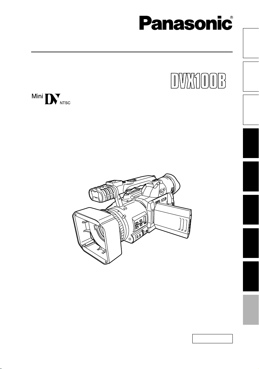
Panasonic DVX100B User Manual
Operating Instructions
F0805S0 -H
Camera-Recorder
Before use
Model No. AG- P
parts
.
ShootingMenus Displays Editing PlaybackReference Preparation Description of
Before operating this product, please read the instructions carefully and save this manual for
future use
ENGLISH
VQT0U08
CAUTION
RISK OF ELECTRIC SHOCK
DO NOT OPEN
CAUTION: TO REDUCE THE RISK OF ELECTRIC
SHOCK, DO NOT REMOVE COVER (OR BACK).
NO USER-SERVICEABLE PARTS INSIDE.
REFER TO SERVICING TO QUALIFIED SERVICE
PERSONNEL.
The lightning flash with arrowhead symbol,
within an equilateral triangle, is intended to
alert the user to the presence of uninsulated
“dangerous voltage” within the product’s
enclosure that may be of sufficient magnitude
to constitute a risk of electric shock to persons.
The exclamation point within an equilateral triangle is intended to alert the user to the presence of important operating and maintenance
(servicing) instructions in the literature accompanying the appliance.
WARNING:
• TO REDUCE THE RISK OF FIRE OR
SHOCK HAZARD, DO NOT EXPOSE
THIS EQUIPMENT TO RAIN OR MOISTURE.
• TO REDUCE THE RISK OF FIRE OR
SHOCK HAZARD, KEEP THIS EQUIPMENT AWAY FROM ALL LIQUIDS. USE
AND STORE ONLY IN LOCATIONS
WHICH ARE NOT EXPOSED TO THE
RISK OF DRIPPING OR SPLASHING
LIQUIDS, AND DO NOT PLACE ANY
LIQUID CONTAINERS ON TOP OF THE
EQUIPMENT.
CAUTION:
TO REDUCE THE RISK OF FIRE OR
SHOCK HAZARD AND ANNOYING
INTERFERENCE, USE THE RECOMMENDED ACCESSORIES ONLY.
CAUTION:
In order to maintain adequate ventilation,
do not install or place this unit in a bookcase, built-in cabinet or any other confined
space. To prevent risk of electric shock or
fire hazard due to overheating, ensure that
curtains and any other materials do not
obstruct the ventilation.
CAUTION:
THE AC RECEPTACLE (MAINS SOCKET OUTLET) SHALL BE INSTALLED NEAR THE
EQUIPMENT AND SHALL BE EASILY ACCESSIBLE.
TO COMPLETELY DISCONNECT THIS EQUIPMENT FROM THE AC MAINS, DISCONNECT
THE POWER CORD PLUG FROM THE AC
RECEPTACLE.
FCC Note:
This equipment has been tested and found to
comply with the limits for a class A digital device,
pursuant to Part 15 of the FCC Rules. These limits are designed to provide reasonable protection
against harmful interference when the equipment is operated in a commercial environment.
This equipment generates, uses, and can radiate radio frequency energy and, if not installed
and used in accordance with the instruction
manual, may cause harmful interference to radio
communications. Operation of this equipment in
a residential area is likely to cause harmful interference in which case the user will be required to
correct the interference at his own expense.
Warnin g:
To assure continued FCC emission limit compliance, the user must use only shielded interface
cables when connecting to external units. Also,
any unauthorized changes or modifications to
this equipment could void the user’s authority to
operate it.
CAUTION:
Danger of explosion or fire if battery is mistreated.
• Replace only with same or specified type.
• Do not disassemble or dispose of in fire.
• Do not store in temperatures over 140°F (60°C).
• Use specified charger for rechargeable batteries.
• Do not recharge the battery if it is not a
rechargeable type.
For Remote Controller
• Replace battery with part No. CR2025 only.
• Do not recharge the battery.
Camera-Recorder
The rating plate is on the underside of the
Camera-Recorder
CAUTION:
TO PREVENT ELECTRIC SHOCK, MATCH
WIDE BLADE OF PLUG TO WIDE SLOT,
FULLY INSERT.
indicates safety information.
2
AC Adapter
The rating plate is on the underside of the AC
Adapter.
Disconnect the AC mains plug from the AC mains
socket when not in use.

Important Safeguards
1. Read Instructions — All the safety and operating
instructions should be read before the unit is operated.
2. Retain Instructions — The safety and operating
instructions should be retained for future reference.
3. Heed Warnings — All warnings on the unit and in
the operating instructions should be adhered to.
4. Follow Instructions — All operating and maintenance instructions should be followed.
5. Cleaning — Unplug this video unit from the wall
outlet before cleaning. Do not use liquid or aerosol
cleaners. Use a dry cloth for cleaning.
6. Attachments — Do not use attachments not recommended by the video product manufacturer as
they may be hazardous.
7. Water and Moisture — Do not use this video unit
near water — for example near a bath tub, wash
bowl, kitchen sink, or laundry tub, in a wet basement, or near a swimming pool, and the like.
8. Accessories — Do not place this video unit on an
unstable cart, stand, tripod, bracket, or table. The
video unit may fall, causing serious injury to a child
or adult, and serious damage to the unit. Use only
with a cart, stand, tripod, bracket, or table recommended by the manufacturer, or sold with the
video unit. Any mounting of the unit should follow
the manufacturer’s instructions and should use a
mounting accessory recommended by the manufacturer.
An appliance and cart combination should be moved with care.
Quick stops, excessive force,
and uneven surfaces may cause
the appliance and cart combination to overturn.
10. Power Sources — This video unit should be operated only from the type of power source indicated
on the marking label. If you are not sure of the type
of power supply to your home, consult your appliance dealer or local power company. For video
units intended to be operated from battery power,
or other sources, refer to the operating instructions.
11. Grounding or Polarization — This video unit may
be equipped with either a polarized 2-wire AC
(Alternating Current) line plug (a plug having one
blade wider than the other) or 3-wire grounding
type plug, a plug having a third (grounding) pin.
The 2-wire polarized plug will fit into the power outlet only one way. This is a safety feature. If you are
unable to insert the plug fully into the outlet, try
reversing the plug. If the plug still fails to fit, contact
your electrician to replace your obsolete outlet. Do
not defeat the safety purpose of the polarized plug.
The 3-wire grounding type plug will fit into a
grounding type power outlet. This is a safety feature. If you are unable to insert the plug into the
outlet, contact your electrician to replace your
obsolete outlet. Do not defeat the safety purpose
of the grounding type plug.
12. Power-Cord Protection — Power-supply cords
should be routed so that they are not likely to be
walked on or pinched by items placed upon or
against them, paying particular attention to cords
of plugs, convenience receptacles, and the point
where they exit from the unit.
9. Ventilation — Slots and openings in the cabinet
are provided for ventilation and to ensure reliable
operation of the video unit and to protect it from
overheating. These openings must not be blocked
or covered. Never place the video unit on a bed,
sofa, rug, or other similar surface, or near or over a
radiator or heat register. This video unit should not
be placed in a built-in installation such as a bookcase or rack unless proper ventilation is provided
or the manufacturer's instructions have been
adhered to.
3

Important Safeguards (continued)
13. Outdoor Antenna Grounding — If an outside
antenna or cable system is connected to the video
unit, be sure the antenna or cable system is
grounded so as to provide some protection against
voltage surges and built-up static charges. Part 1
of the Canadian Electrical Code, in USA Section
810 of the National Electrical Code, provides information with respect to proper grounding of the
mast and supporting structure, grounding of the
lead-in wire to an antenna discharge unit, size of
grounding conductors, location of antenna discharge unit, connection to grounding electrodes,
and requirements for the grounding electrode.
ANTENNA LEAD IN WIRE
GROUND
CLAMPS
ELECTRIC
SERVICE
EQUIPMENT
NEC — NATIONAL
ELECTRICAL CODE
ANTENNA DISCHARGE UNIT
(NEC SECTION 810-20)
GROUNDING CONDUCTORS
(NEC SECTION 810-21)
GROUND CLAMP
POWER SERVICE GROUNDING
ELECTRODE SYSTEM
(NEC ART 250, PART H)
14. Lightning — For added protection of this video unit
receiver during a lightning storm, or when it is left
unattended and unused for long periods of time,
unplug it from the wall outlet and disconnect the
antenna or cable system. This will prevent damage
to the video unit due to lightning and power-line
surges.
15. Power Lines — An outside antenna system should
not be located in the vicinity of overhead power
lines or other electric light or power circuits, or
where it can fall into such power lines or circuits.
When installing an outside antenna system,
extreme care should be taken to keep from touching such power lines or circuits as contact with
them might be fatal.
16. Overloading — Do not overload wall outlets and
extension cords as this can result in a risk of fire or
electric shock.
17. Objects and Liquids — Never push objects of any
kind into this video unit through openings as they
may touch dangerous voltage points or short out
parts that could result in a fire or electric shock.
Never spill liquid of any kind onto the video unit.
18. Servicing — Do not attempt to service this video
unit yourself as opening or removing covers may
expose you to dangerous voltage or other hazards.
Refer all servicing to qualified service personnel.
19. Damage Requiring Service — Unplug this video
unit from the wall outlet and refer servicing to qualified service personnel under the following conditions:
a. When the power-supply cord or plug is dam-
aged.
b. If any liquid has been spilled onto, or objects
have fallen into the video unit.
c. If the video unit has been exposed to rain or
water.
d. If the video unit does not operate normally by
following the operating instructions. Adjust only
those controls that are covered by the operating
instructions, as an improper adjustment of other
controls may result in damage and will often
require extensive work by a qualified technician
to restore the video unit to its normal operation.
e. If the video unit has been dropped or the cabi-
net has been damaged.
f. When the video unit exhibits a distinct change in
performance — this indicates a need for service.
20. Replacement Parts — When replacement parts
are required, be sure the service technician has
used replacement parts specified by the manufacturer or have the same characteristics as the original part. Unauthorized substitutions may result in
fire, electric shock or other hazards.
21. Safety Check — Upon completion of any service
or repairs to this video unit, ask the service technician to perform safety checks to determine that the
video unit is in safe operating order.
4

Contents
Before use
Important Safeguards ................................... 3
Read this first!................................................ 7
Accessories.................................................... 7
Operating precautions................................... 8
Checking the system operations................ 10
Items to prepare.............................................. 10
Connect the AC power supply cord ............... 10
Insert the Mini DV cassette tape..................... 10
Start shooting.................................................. 11
Check what you have shot (rec check)........... 12
Eject the tape ..................................................12
Turn off the unit .............................................. 13
Disconnect the power cord ............................ 13
Adjusting the hand strap............................. 14
Attaching the shoulder strap ...................... 14
Attaching the lens hood .............................. 15
Attaching the lens-cap strap....................... 15
Cassette tapes.............................................. 15
Description of parts
Description of parts .................................... 16
Camera-recorder ............................................ 16
Remote control .............................................. 19
Preparation
The remote control ...................................... 20
Insert the battery............................................. 20
Remote control setup...................................... 20
The battery ................................................... 21
Charging ......................................................... 21
Attaching the battery....................................... 22
Detaching the battery...................................... 22
Viewfinder .................................................... 23
Using the viewfinder ....................................... 23
Using the LCD ................................................ 24
Emphasizing outlines...................................... 24
Adjusting the screen display........................... 25
Time data ..................................................... 26
Setting the calendar........................................ 26
Recharging the built-in battery ....................... 27
Setting user information.................................. 27
Setting the time code ..................................... 28
Specifying the time code (TC PRESET)......... 29
Shooting
Regular shooting ......................................... 31
Preparation and inspections........................... 31
Shooting in auto mode ................................... 31
Shooting techniques for different targets 32
Check what you have shot (rec check) .......... 32
Finding specific scenes (image search)......... 32
Zoom ............................................................. 32
Low-angle shooting........................................ 33
Self-portrait shooting...................................... 33
Zebra pattern.................................................. 33
Marker ............................................................ 33
ONE-SHOT recording .................................... 34
Changing the image size................................ 34
Optical Image Stabilizer ................................ 35
Using the USER buttons ............................... 35
Backlight compensation ................................. 35
Index recording .............................................. 35
Color bars....................................................... 35
Adding effects to images................................ 35
Backup recording ........................................... 36
Switching to manual mode............................. 36
Adjusting the volume while shooting .............. 36
Shooting in progressive mode ................. 37
Focus ........................................................... 38
Adjusting the shutter speed ...................... 39
Slow shutter mode ......................................... 40
Synchro scan ................................................. 40
Adjusting the white balance ...................... 41
White balance adjustments............................ 41
Using presets ................................................. 42
Black balance adjustments ............................ 42
Auto Tracking White (ATW) ........................... 42
Adjusting Iris, Gain, and Light Intensity ... 43
Iris adjustments.............................................. 43
Adjusting the gain........................................... 43
Light intensity adjustments............................. 43
Switching Audio Input ................................ 44
Using the built-in microphone......................... 44
Using another microphone and
audio equipment......................................... 44
Adjusting the recording level.......................... 44
Using scene files......................................... 45
Changing scene file settings .......................... 45
Transferring scene files ............................. 47
5

Contents (continued)
Playback
Playback ....................................................... 48
Adjusting the volume ...................................... 49
Viewing images on a television .......................49
Checking the date and time............................ 49
Variable-speed playback .............................50
Slow playback .................................................50
Frame-by-frame playback............................... 50
Fast-forward and rewind................................. 50
Index search ...................................................50
Variable speed search ....................................51
End search ......................................................51
Using the Counter ........................................ 52
Counter display ...............................................52
Memory stop mode .........................................52
1394TC preset mode ......................................52
Editing
Connecting external units ........................... 53
Headphones ...................................................53
External microphone .......................................53
Digital video equipment ..................................54
Television ........................................................55
Video deck ......................................................55
Audio dubbing .............................................56
Dubbing ........................................................58
Analog input ....................................................58
Analog output ..................................................59
Digital input/output ..........................................60
Menus
Using the setup menus ...............................66
Using the setup menus ................................... 66
Initializing the menu settings .......................... 67
Setup menu structure ..................................68
Camera mode menu ....................................... 68
VCR mode menu ............................................ 68
Setup menu list ............................................69
SCENE FILE screen ....................................... 69
CAMERA SETUP screen ............................... 71
SW MODE screen .......................................... 71
AUTO SW screen ........................................... 72
PLAYBACK FUNCTIONS screen ................... 73
RECORDING SETUP screen ......................... 74
AV IN/OUT SETUP screen ............................. 75
DISPLAY SETUP screen ............................... 76
OTHER FUNCTIONS screen ......................... 77
Reference
Before calling for service ............................79
Condensation ...............................................82
Tally lamp .....................................................82
System resetting ..........................................82
Video Heads .................................................83
Cleaning ........................................................83
Storage Precautions ....................................84
Specifications ..............................................85
Displays
Screen displays ...........................................61
Displays in CAMERA and VCR modes ...........61
In VCR mode only ...........................................64
Warnings .........................................................64
Setting the DISPLAY items .............................65
• LEICA is a trademark of Leica Microsystems IRGmbH.
• DICOMAR is a trademark of Leica Camera AG.
All other explanations, company names, and product names are the registered trademarks of the
respective companies.
6
Read this first!
Always take some trial shots before actual shooting.
• When shooting impor tant events (such as weddings), always take some trial shots and check that the
sound and images have been recorded properly before actual shooting.
Panasonic makes no guarantees for your recordings.
• Please understand that Panasonic makes no guarantees for your recordings in cases where images and/
or sound were not recorded as you intended due to problems with the camera-recorder or cassette.
Respect copyrights
• Copyright laws forbid the use of video and audio material you have recorded for any purpose other than
your own personal enjoyment. Remember that restrictions apply to the shooting of cer tain material even if
it is intended for private use.
Note concerning illustrations in these instructions
• Illustrations (camera-recorder, menu screens, etc.) in these operating instructions differ slightly from the
actual camera-recorder.
References
• References are shown as (Page 10).
Tapes you can use
• You can use tapes with this mark- .
IMPORTANT
“Unauthorized recording of copyrighted television programs, video tapes and other materials may infringe the
right of copyright owners and be contrary to copyright laws.”
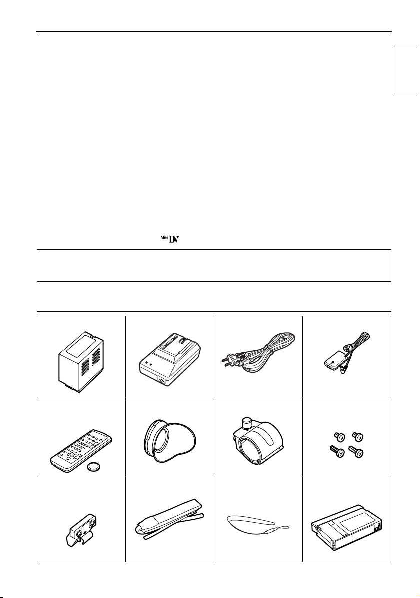
Accessories
Before use
Battery * AC Adapter * AC power supply cord DC cord
Wireless remote
control and button
battery (CR2025)
Microphone holder
adapter
* For part numbers for the battery and AC adapter, see “Optional Units” (Page 86).
Eye cup Microphone holder 2x 6-mm screws
2x 12-mm screws
Shoulder belt Lens cap strap Mini DV cassette tape
(AY-DVM63MQ)
7

Operating precautions
Do not allow any water to get into the camera-recorder when using it in the rain or
snow or at the beach.
• Failure to heed this caution will cause the camerarecorder or cassette to malfunction (and may result in
irreparable damage).
Take precautions not to drop the camera when
moving it.
• Strong impacts may damage the camera and cause it
to stop working.
• Handle the camera with care, using the hand strap or
shoulder strap to carry it.
Keep the camera-recorder away from equipment (such as TV sets and video game
machines) that generate magnetic fields.
• Using the camera-recorder on top of or near a TV set
may cause distortion in the images and/or sound due
to the electromagnetic waves that the set emits.
• The powerful magnetic fields generated by speakers
or large motors may damage your tape recordings or
distort the images.
• The electromagnetic waves emitted from a microcomputer will adversely affect the camera-recorder,
causing the images and/or sound to be distorted.
• If the camera-recorder is so adversely affected by
products that generate magnetic fields that it no
longer operates properly, turn it off and remove the
battery or unplug the AC adapter from the power outlet. Then install the battery again or re-connect the
AC adapter. After this, turn the camera-recorder back
on.
Do not use the camera-recorder near radio
transmitters or high-voltage equipment.
• Using the camera-recorder near a radio transmitter or
high-voltage equipment may adversely affect the
recorded images and/or sound.
Do not allow any sand or dust to get into the
camera-recorder when using it at the beach
and other similar places.
• Sand and dust can damage the camera-recorder and
cassette. (Be especially careful when inserting or
removing the cassettes.)
Do not spray the camera with insect sprays or
other volatile substances.
• These can warp the camera or cause the finish to
come off.
• Do not leave the camera-recorder in contact with
rubber or PVC products for extended periods of time.
After use, remove the cassette and battery and
disconnect the AC power supply cord.
• The tape can become slack or damaged if you leave
it in the camera.
• The battery can over discharge if you leave it in the
camera and it may become impossible to recharge it.
AC adapter and battery
• If the battery is extremely hot or cold, the CHARGE
lamp will blink several times before charging starts.
• If the CHARGE lamp continues to blink even when
the battery temperature is normal, there may be
something wrong with the battery or AC adapter.
Contact your dealer.
• The battery takes longer to charge when it is warm.
• The AC adapter can interfere with radio reception so
keep radios at least 1 meter away from it.
• The AC adapter may make some noise when you are
using it, but this is normal.
8
Battery characteristics
This camera-recorder uses a rechargeable lithiumion battery that uses its internal chemical reaction
to generate electrical energy. This reaction is easily
influenced by the ambient temperature and
humidity, and the battery’s effective operating time
is reduced as the temperature rises or falls. In very
low temperatures, the battery may last only 5
minutes.
Protective circuitry functions if you use the battery
where it is very hot and you will have to wait before
you can use it again.
Remove the battery after use
Completely remove the battery. (The battery
continues to be used even if you have turned the
camera off.) The battery can over discharge if you
leave it in the camera and it may become
impossible to recharge it.
Disposing of spent batteries
• The battery will become unchargeable.
Rather than throwing the battery into the garbage,
take it to a store that can assist in recycling it.
Protect the battery terminals.
Keep the battery’s terminal area free of dust and
other foreign matter.
If you accidentally drop the battery, check that the
battery and its terminals have not been damaged.
You can damage the camera and AC adapter if you
try to use or recharge a damaged battery.
Liquid crystal displays
• Images or letters can get burned onto the screen of
the LCD or viewfinder if they are displayed for a long
time, but you can fix this by leaving the camera off for
several hours.
• The liquid crystal parts are highly precise with
99.99% of the pixels effective
This leaves less than 0.01% of pixels that may not
light or may remain on all the time. These
phenomena are normal and will have no effect on the
images you shoot.
• Condensation may form if you use the camera where
temperatures fluctuate. Wipe dry with a soft, dry
cloth.
• The LCD may appear dim after immediately turning
on a cold camera, but will brighten as the camera
warms up.
Do not point the lens or viewfinder at the sun.
Doing so may damage the parts inside.
Protective caps for the connectors
Keep the protective caps fitted over any connectors
that are not being used.
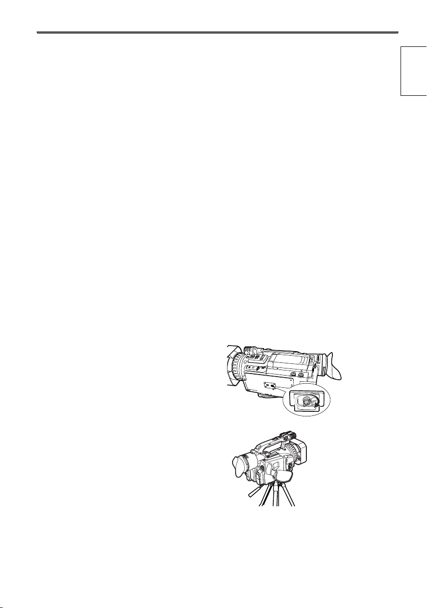
Mounting the camera-recorder on a tripod
The tripod mounting hole is 5.5 mm deep. Do not
force the tripod screw beyond this depth.
You can damage the camera-recorder if you use
any screw other than 1/4-20UNC.
Before use
Attach the tripod
to the tripod
hole
9
Checking the system operations
After purchase, do these system checks to ensure
that the unit is working properly before you attempt
to shoot anything.
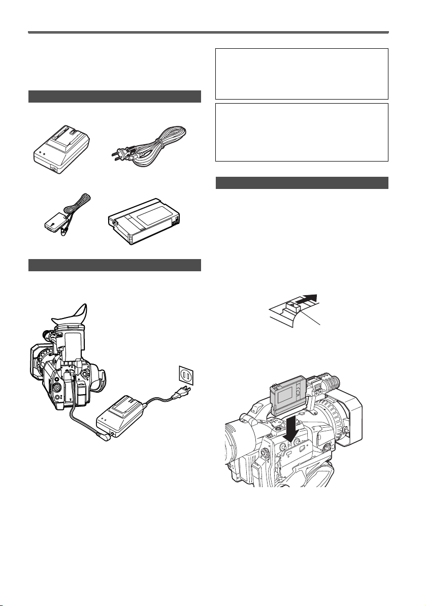
Items to prepare
AC adapter AC power supply cord
DC cord Mini DV cassette tape
Connect the AC power supply cord
Connect the cords properly as shown in the
figure above.
• You cannot charge the battery when supplying
power to the camera-recorder from the AC
adapter.
CAUTION:
• This unit will operate on 110/120/220/240 V AC.
An AC plug adapter may be required for voltages
other than 120 V AC.
If a conversion plug is required, consult with your
dealer as to which one is to be purchased.
Insert the Mini DV cassette tape
1 Slide the EJECT switch in the direction shown
by the arrow to open the cassette holder.
The cassette holder opens automatically when
the cassette cover is fully open.
• The cassette holder will not open if the
camera is not supplied with power (AC
adapter or battery).
EJECT switch
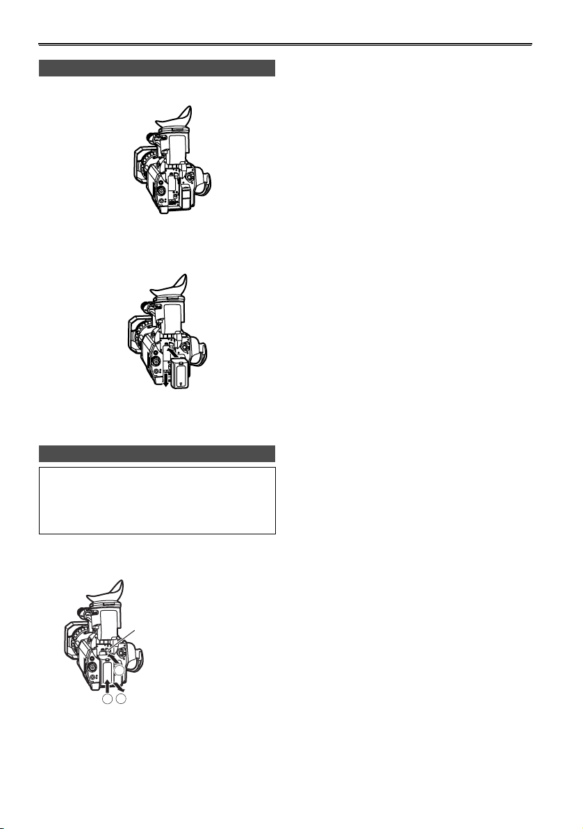
1 Lift up the viewfinder.
2 Press on the DC cord’s battery connector and
move it down until it clicks into place.
3 Connect the DC cord to the AC adapter.
4 Plug the AC cord into the power outlet.
5 Return the viewfinder to its original position.
10
2 Insert the cassette as shown in the diagram.
H
S
U
P
3 Press PUSH to close the cassette holder.
The holder automatically goes into position
when you close it correctly.
PUSH
H
S
U
P
• Do not try to insert or eject the tape by just
holding the cassette cover.
• Insert and remove cassette tapes after putting
the camera-recorder down on a stable, flat
surface or hold it with both hands to keep it
stable.
• Do not force the cassette holder while it is
moving. Trying to do so could damage the
camera.
• Close the cassette cover only after the cassette
holder is completely in position. Trying to close
the cover while the cassette holder is moving
could damage the camera.
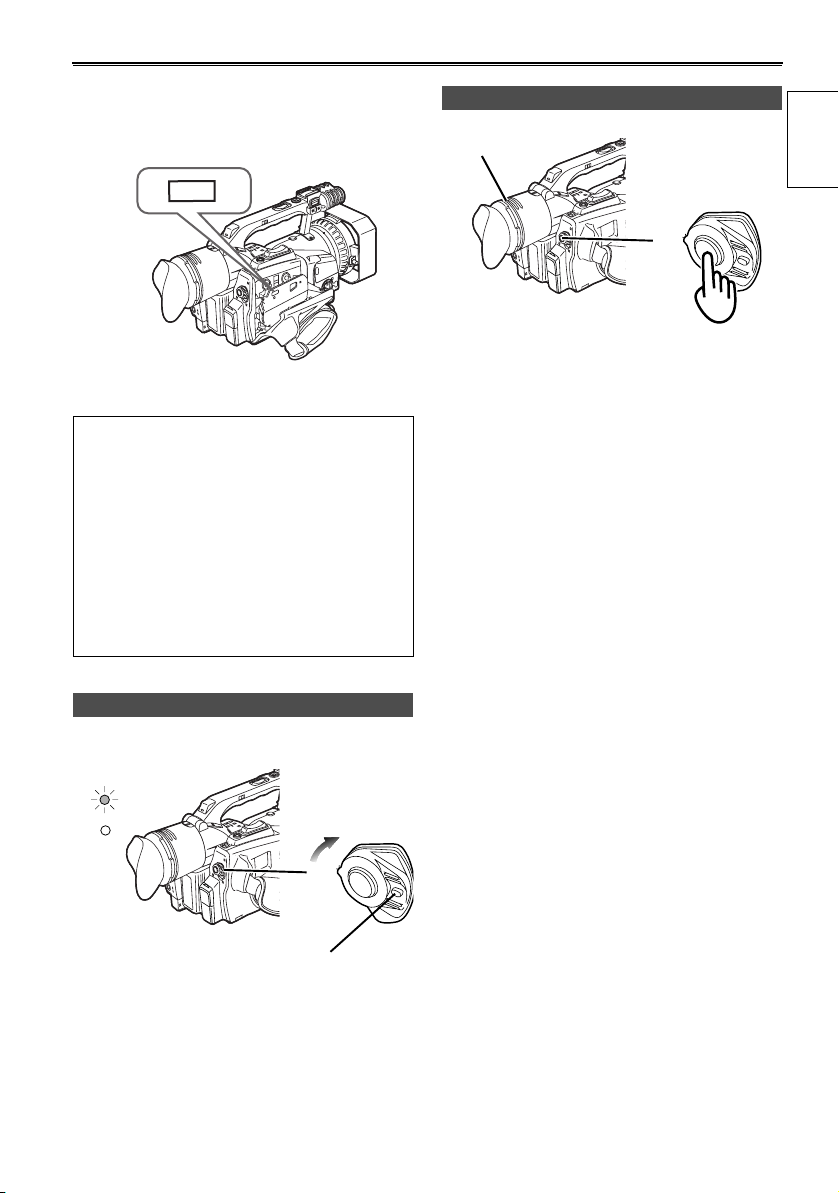
Start shooting
Viewfinder
POWER
ON
OFF
1 Look at your subject through the viewfinder.
2 Press the START/STOP button on the POWER
switch to start shooting.
Press START/STOP again to return the camera
to the shooting standby mode.
Before use
Turn on the camera
CAMERA
VCR
Lock release
While pressing the lock release, move the POWER
switch to ON.
The CAMERA lamp lights red (camera mode) and
the camera is now in the shooting standby mode.
OFF
POWER
ON
11
Checking the system operations (continued)
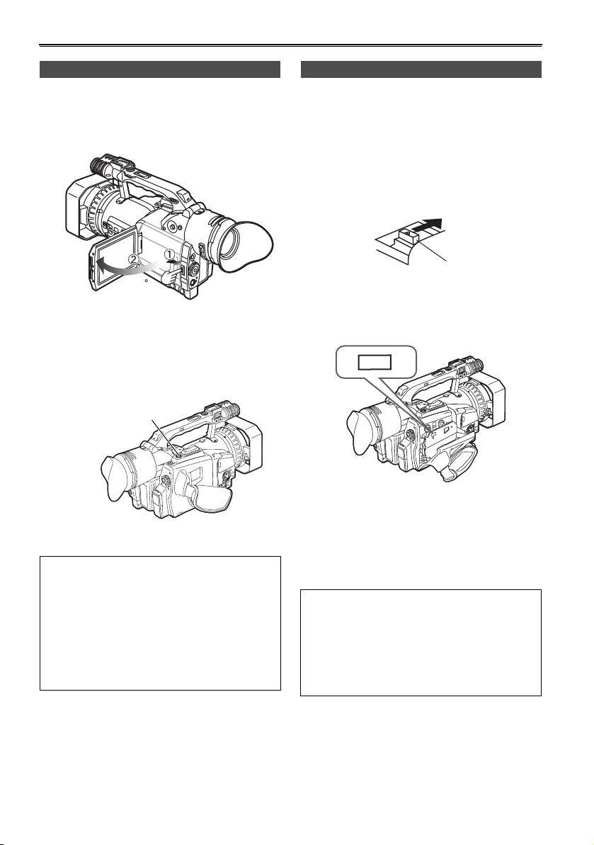
Check what you have shot (rec check)
1 Press the OPEN button in the direction shown
by arrow (1) to open the LCD.
It can open out to 120 degrees. Do not try to
open it further as this will damage the camera.
120
2 While in the shooting standby mode, press the
REC CHECK button.
A few seconds of the last thing you shot play,
and then the camera returns to the shooting
standby mode.
REC CHECK button
Eject the tape
1 Slide the EJECT switch in the direction shown
by the arrow to open the cassette cover.
When the cassette cover is fully open, the
cassette holder automatically opens out.
• The cassette holder will not open if the
camera is not supplied with power (AC
adapter or battery).
Lock release
2 Remove the cassette.
Press PUSH to close the cassette holder.
PUSH
H
S
U
P
Power saving mode
The camera-recorder performs as follows when you
pause or leave it in standby mode for about 5
minutes, and do not perform any specified
operations.
ON: The camera recorder turns off automatically
OFF: The cylinder head pauses and goes into
standby mode without cutting the power.
See the setup menus, OTHER FUNCTIONS
screen, POWER SAVE (
Page 78) for details.
12
3 Close the cassette cover only after the cassette
holder is completely in position.
Do not close the cassette cover while the
cassette holder is moving as this can damage
the mechanism.
• Make sure the camera-recorder is supplied with
power before operating the EJECT switch.
• Close the cassette holder again if you are not
going to insert another tape.
• Do not open the cassette cover while you are
recording.
Recording continues, and the open cover allows
outside light and dust to adversely affect the tape.
Turn off the unit
CAMERA
VCR
While pressing the lock release, move the POWER
switch to OFF.
The red CAMERA lamp goes out.
POWER
ON
OFF
Lock release
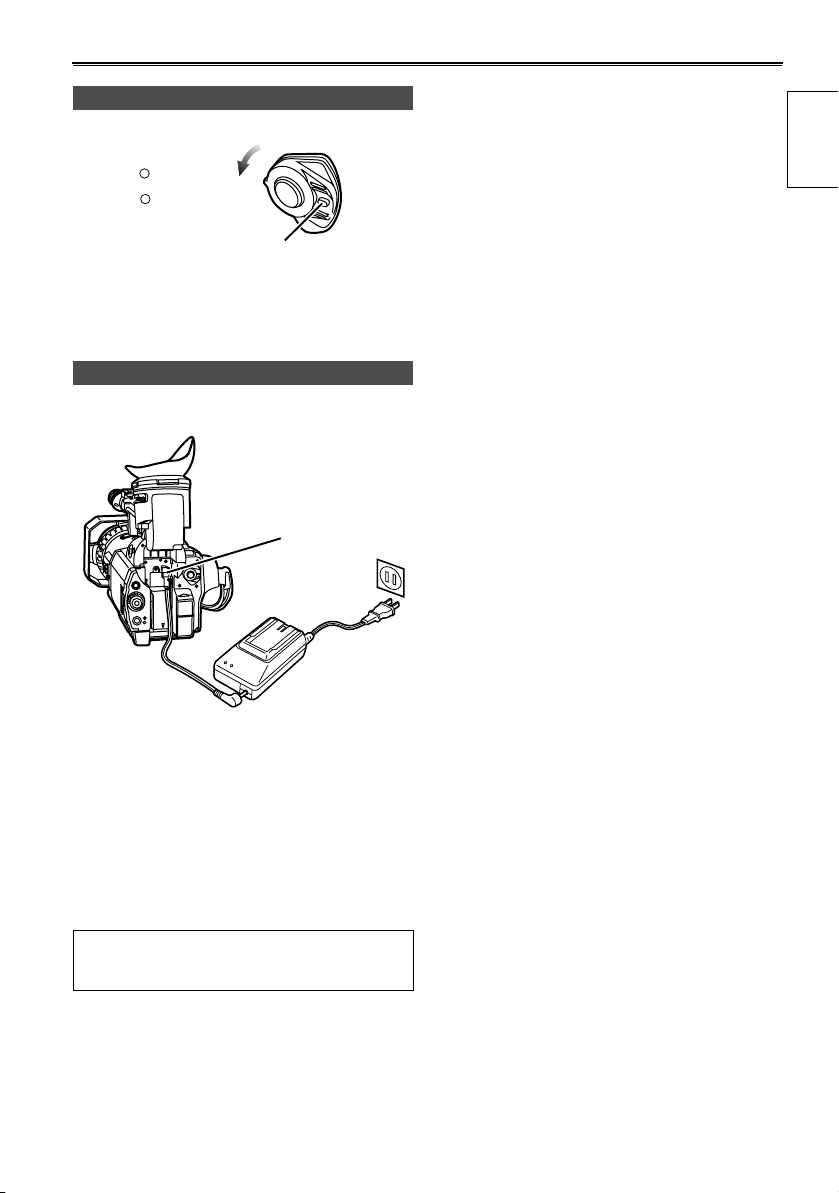
Disconnect the power cord
Battery release
Before use
1 Unplug the AC cord from the power outlet.
2 Lift up the viewfinder.
3 While pressing the battery release, pull the DC
cord’s battery connector towards you.
4 Return the viewfinder to its original position.
• Turn POWER to OFF and check that the POWER
lamp (CAM/VCR) has gone off before
disconnecting the power cord.
13
Adjusting the hand strap
Adjust the hand strap to suit your hand.
1 Open the cover and adjust the length.
2 Close the cover.
• Make sure the cover is fully closed.
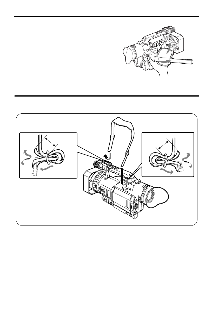
Attaching the shoulder strap
Attach the shoulder strap and use it as a precaution
against dropping the camera.
20mm or more
20mm or more
14
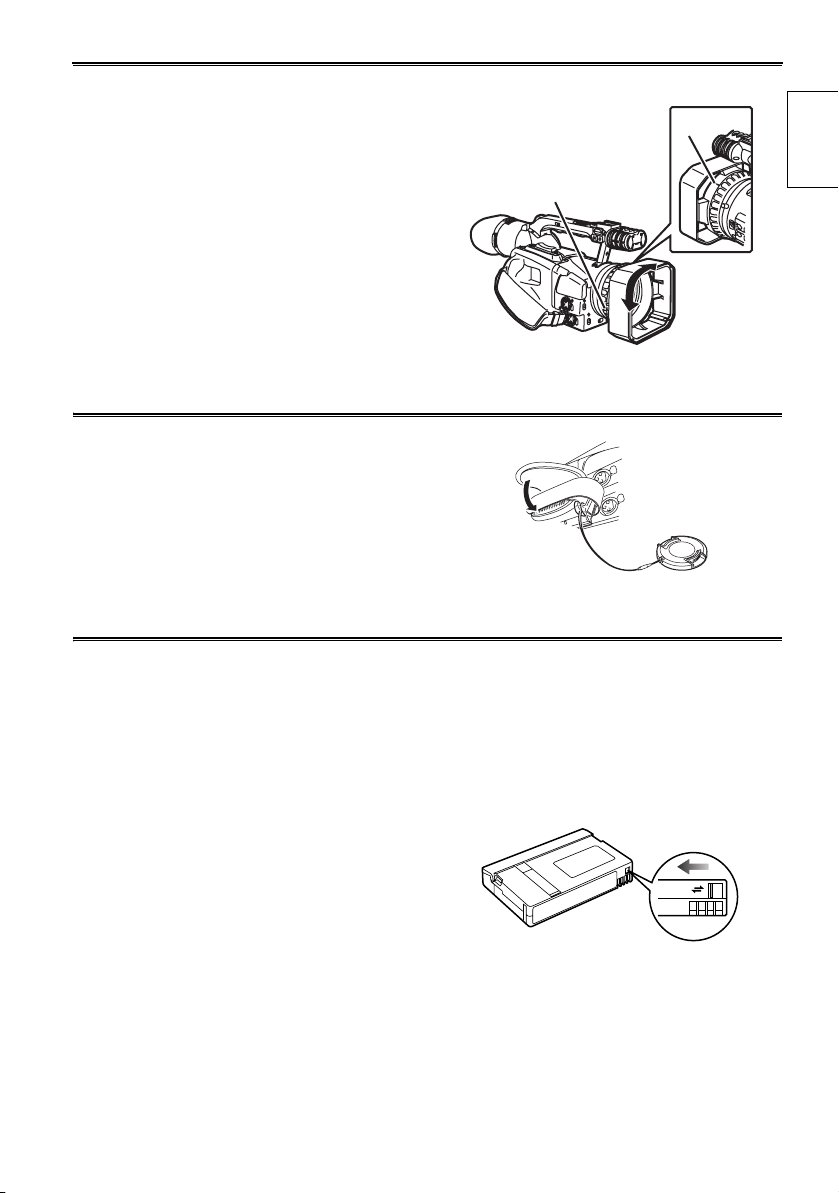
Attaching the lens hood
Detaching the lens hood
• Loosen the screw and turn the lens hood
counterclockwise to detach it.
Attaching the lens hood
• Position the lens hood so the mark is at the top and fit
it onto the lens.
• Turn the lens hood clockwise and fix in position with
the screw.
Attaching the lens-cap strap
Thread the strap through the lens cap. Thread one end
through the hand strap.
Cassette tapes
g Use the following mini DV cassette tapes with
this camera-recorder.
AY-DVM63PQ Professional series tape
(60 minutes in SP mode)
AY-DVM63MQ Master series tape
(60 minutes in SP mode)
g Picture quality does not worsen if you shoot in LP
mode, but you may notice some block noise and
there may be other limitations.
Block noise and feature limitations occur in the
following situations.
• When you play a tape on other digital video
equipment that you have shot in LP mode on
this camera.
• When you play a tape in this camera that you
have shot in LP mode on other digital video
equipment.
• When you have shot in LP mode and try to play
it on other digital video equipment that doesn’t
have an LP mode.
• During slow motion or still-picture playback
• When using the camera’s search functions
Mark
Screw
g Audio dubbing cannot be performed in the LP
mode as the tracks on the tape are narrower
than the heads.
Preventing accidental erasure
To prevent erasing the recordings on a tape by
accident, set the tab on the cassette to SAVE.
REC
SAVE
Before use
15
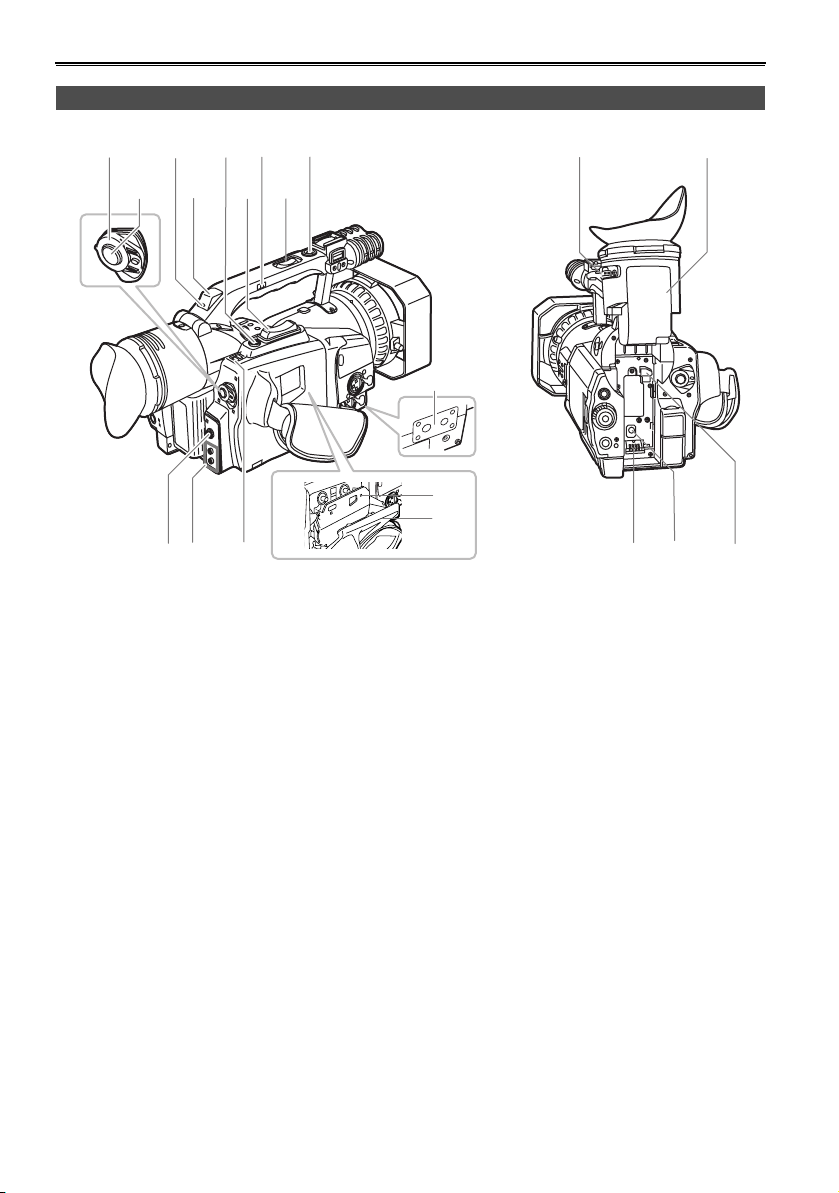
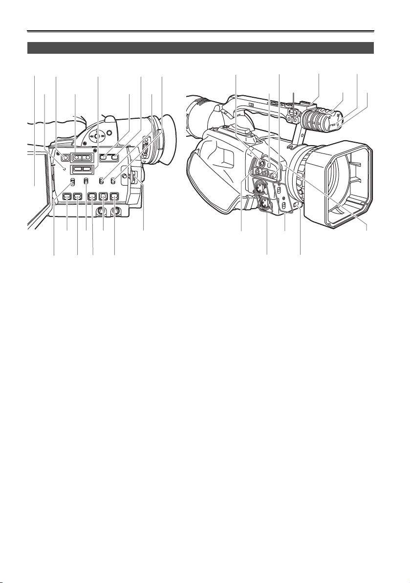
Description of parts
Camera-recorder
1 3 5 7 9 15 16
2468
PO
WER
O
N
O
FF
14
Bottom
13
PUSH
10 11 12
1 POWER switch (Page 11)
2 START/STOP button (Page 11)
3 Rear tally lamp (Page 82)
4 Rear remote control sensor
5 REC CHECK button (Page 12)
6 Zoom button (Page 32)
7 HANDLE ZOOM switch (Page 32)
8 Handle zoom button (Page 32)
9 Handle START/STOP button (Page 33)
10 PHONES jack (3.5-mm stereo) (Page 53)
11 Remote control jacks
FOCUS/IRIS (3.5 mm mini jack)
Connect a remote control to remotely control
focus and iris.
ZOOM S/S (2.5 mm Super mini jack)
Connect a remote control to remotely control
zoom and start/stop.
12 EJECT switch (Page 10)
13 Cassette section (Page 10)
a) Cassette holder
b) Cassette cover
14 Tripod hole (Page 9)
15 Viewfinder diopter dial (Page 23)
16 Viewfinder (Page 23)
a
b
17 18 19
17 Power terminals (Page 10)
18 DC INPUT terminal (7.9 V)
19 Battery release (Pages 13 and 22)
16
20 22 24 26
21 23 25 27
A
W
B
parts
Description of
29 31 33 35
28 30 32 34 36 38
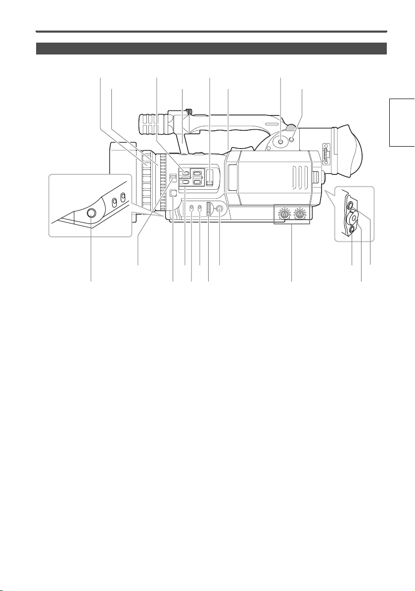
20 Focus ring (Page 38)
21 Zoom ring (Page 32)
If you don’t need the zoom ring pin, fit it into the
provided hole (23) so that you don’t lose it.
22 AUTO butt on (Pages 31 and 36)
23 Hole for the zoom ring pin
24 ND FILTER switch (Page 43)
25 Speaker (Page 49)
26 OPERATION lever (Pages 32, 48, and 66)
27 MENU button (Page 66)
28 AWB button (Pages 41 and 42)
29 FOCUS switch (Page 38)
30 PUSH AUTO button (Page 38)
31 USER buttons 1 to 3 (Page 35)
32 GAIN switch (Page 43)
33 WHITE BAL switch (Page 41)
34 IRIS dial (Page 43)
35 IRIS button (Page 43)
36 AUDIO control (Page 44)
37 CAMERA/VCR button and lamp (Page 48)
38 Scene file dial (Page 45)
37 39
39 EVF DTL/END SEARCH button (Pages 24 and
51)
17
Description of parts (continued)
40 42 44
46 48
47454341
50 52 54 56
51 53 5549
40 LCD monitor (Pages 9 and 24)
41 RESET button (Page 24)
42 DISPLAY/AUDIO DUB button (Pages 56 and
65)
43 VCR REC buttons (Pages 58 and 60)
44 AUDIO MON/VAR buttons (Pages 49, 50, and
51)
45 SHUTTER button (Page 39)
46 SPEED SEL button (Page 39)
47 INPUT1 switch (MIC POWER +48 V)(Page 44)
48 INPUT2 switch (MIC POWER +48 V)(Page 44)
49 CH1 SELECT switch (Page 44)
50 COUNTER button (Page 52)
51 COUNTER RESET/TC SET button (Pages 25
and 52)
52 CH2 SELECT switch (Page 44)
53 MODE CHK button(Page 65)
54 ZEBRA button(Page 33)
55 OIS button (Page 35)
56 OPEN button (Page 24)
57
59 61 63
58 60 62 64
65 67 69
66 68
57 S-VIDEO IN/OUT terminal (Page 55)
58 DV terminal (Page 36)
59 VIDEO IN/OUT terminal (pin jack) (Page 55)
60 Microphone shoe (Page 53)
61 Light shoe
62 Built-in stereo microphone (Page 44)
63 Front tally lamp (Page 82)
64 Front remote control sensor
65 AUDIO IN/OUT CH1/CH2 terminal (pin jack)
(Page 55)
66 INPUT 1/2 terminal (XLR, 3 pin) (Pages 44
and 53)
67 INPUT 1/2 switch (Page 44)
68 ZOOM switch (Page 32)
69 White balance sensor (Page 41)
18
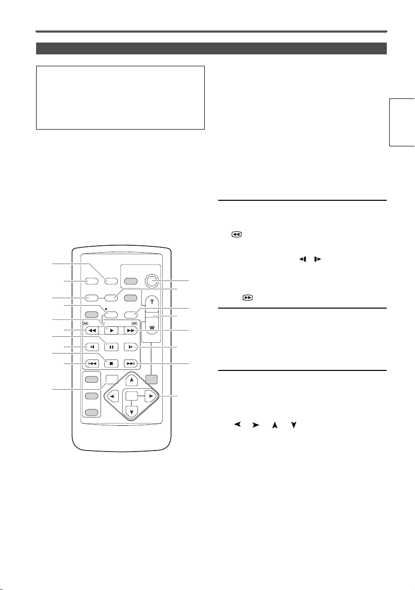
Remote control
The following buttons are for functions that
cannot be executed on the camera-recorder.
•PHOTO SHOT •TITLE
• MULTI/P-IN-P • SELECT
•STORE •OFF/ON
•PB.ZOOM
12
16
1
2
3
6
7
8
9
10
11
OSD
COUNTER
MULTI/
P-IN-P
STILL ADV
INDEX
SELECT
STORE
OFF/ON
P.B.DIGITAL
DATE/
TIME
RESET TITLE
REC A.DUB
PLAY/REW FF/
PAU S E
STOP INDEX
VAR.
SEARCH
PHOTO
SHOT
STILL ADV
MENU
ITEM
START/
STOP
ZOOM
VOL +
-
PB.
ZOOM
4
15
10
17
SET
1 DATE/TIME button (Page 49)
2 OSD button(Page 49)
3 COUNTER button
Same function as the COUNTER button on the
main unit.
4 COUNTER RESET button
Same function as the COUNTER RESET button
on the main unit.
5 A.DUB button
Same function as the AUDIO DUB button on the
main unit.
6 REC button (Pages 58 and 60)
(Used during VCR mode)
7 PLAY button (q)(Page 48)
8 /REW button (t)(Page 48)
9 PAUSE button (h)(Page 48)
10 STILL ADV button ( , )(Page 50)
11 INDEX buttons (u, i)(Page 50)
14
12 STOP button (g)(Page 48)
13 FF/ button (y)(Page 50)
5
Buttons for shooting and volume control
14 START/STOP button
13
Same function as the START/STOP button on
the main unit.
15 ZOOM/VOL buttons (Pages 32 and 49)
11
16 VAR. SEARCH button (Page 51)
17 MENU button
Functions the same as the MENU button on the
camera.
[], [], [], [] buttons
Function the same as the t, y, e, r buttons
on the camera.
parts
Description of
19
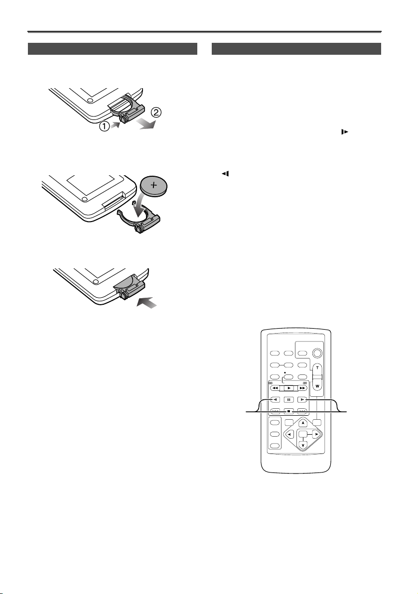
The remote control
Insert the battery Remote control setup
Push the catch in the direction shown by arrow
1
(1) to remove the holder.
2 Insert the batter y with the “+” marked side
facing up.
3 Return the holder to its original position.
When using two camera-recorders simultaneously,
set this camera-recorder and the remote control to
either [VCR1] or [VCR2] so the remote control does
not operate the wrong camera-recorder by mistake.
Setting
• Wireless remote control
Press the STOP (g) and STILL ADV ( ) buttons
at the same time to set the remote control unit for
use with VCR1.
Alternatively, press the STOP (g) and STILL ADV
( ) buttons at the same time to set the remote
control unit for use with VCR2.
When the battery in the remote control unit is
replaced, the remote control unit is set for use
with VCR1.
•Camera
In the setup menus, OTHER FUNCTIONS
screen, REMOTE, set to VCR1 or VCR2.
(Page 77)
If different settings are used for the camerarecorder and remote control unit, “REMOTE” lights
in red on the viewfinder and LCD monitor.
• When the battery (CR2025) has run out, replace it
with a new one. (The battery lasts about one year,
depending on the frequency of use.)
If the remote control unit fails to work even when it is
operated near the camera-recorder’s remote control
sensor, the battery has run out.
• Keep the battery out of the reach of children.
20
VCR2
OSD
COUNTER
MULTI/
P-IN-P
STILL ADV
INDEX
SELECT
STORE
OFF/ON
P.B.DIGITAL
DATE/
PHOTO
TIME
SHOT
RESET TITLE
REC A.DUB
PLAY/REW FF/
PAUSE
STILL ADV
STOP INDEX
VAR.
SEARCH
START/
STOP
ZOOM
VOL+
-
PB.
ZOOM
MENU
SET
ITEM
VCR1
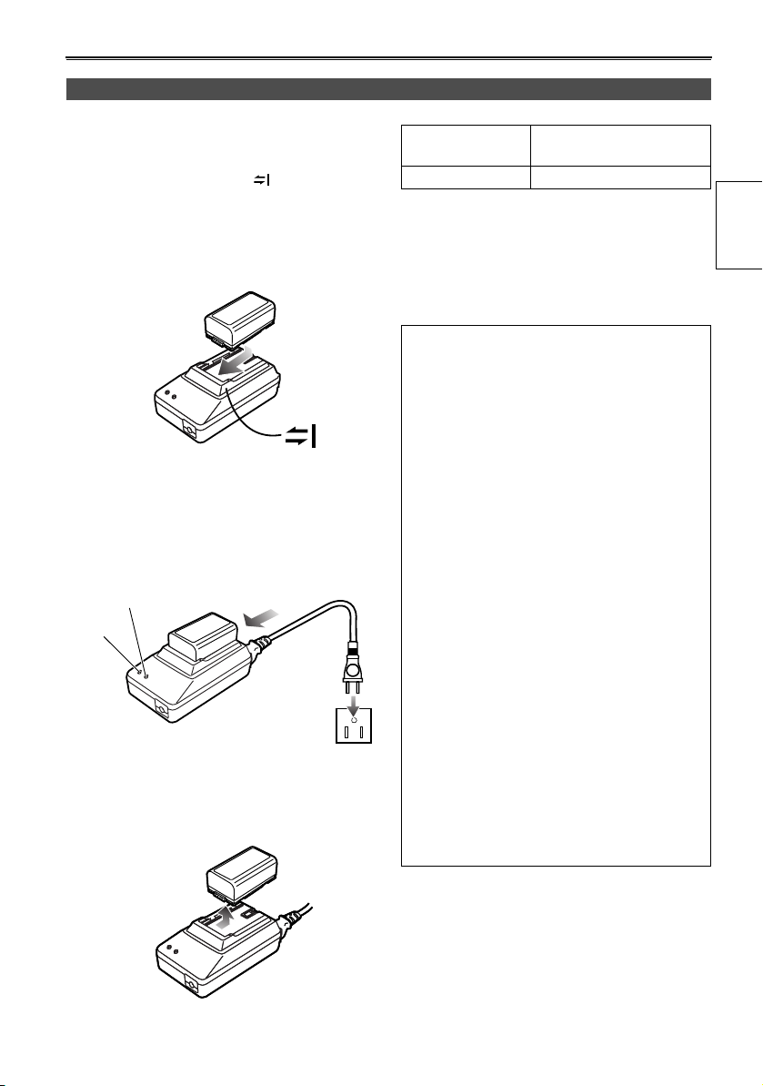
The battery
Charging
Before using the battery, fully charge it with the AC
adapter.
Keep a spare battery with you.
1 Align the battery with the “ ” marking on the
AC adapter, place it flat, and slide it in the
direction shown below.
• You cannot charge the battery if the DC cord
is connected to the DC OUT connector, so
disconnect it first.
2 Plug the AC cord into the power outlet.
• The POWER lamp and CHARGE lamp on the
AC adapter light, and charging begins.
• If the CHARGE lamp does not light when
attached, detach the battery and then attach
it again.
CHARGE
POWER
3 When the battery is charged, the CHARGE
lamp on the AC adapter goes out.
4 Slide the battery and remove it.
Recording time of included battery
Recharging time
Approx. 330 min. Approx. 360 (or 300) min.
• Times given above are approximate. Figures in
parentheses show the recording times when you use
the LCD monitor.
• The times apply when the ambient operating
temperature is 68°F (20°C) and humidity is 60%.
Charging may take longer at other temperatures and
humidity levels.
• Keep metal objects (such as necklaces
and hairpins) away from the battery. Shortcircuiting may occur across the terminals,
causing the battery to heat up, and you
may seriously burn yourself if you touch
the battery in this state.
• The battery becomes hot while it is being used or
charged.
The camera-recorder itself also becomes hot
during use.
• The recordable time reduces if you repeatedly
start and stop recording.
• Discharge the battery before storing it.
When storing it for an extended time, charge it at
least once a year, use up its charge in the
camera-recorder, and then store it again.
• If the battery is extremely hot or cold, the
CHARGE lamp will blink several times before
charging starts.
• If the CHARGE lamp continues to blink even
when the battery temperature is normal, there
may be something wrong with the battery or AC
adapter. Contact your dealer.
• The battery takes longer to charge when it is
warm.
• The AC adapter can interfere with radio reception
so keep radios at least 1 meter away from it.
• The AC adapter may make some noise when you
are using it, but this is normal.
• You cannot charge the battery when supplying
power to the camera-recorder from the AC
adapter.
Continuous recording
time
Preparations
21
The battery (continued)
Attaching the battery
1 Lift up the viewfinder.
2 Press on the battery and move it down until it
clicks into place.
3 Return the viewfinder to its original position.
Detaching the battery
• Turn POWER to OFF and check that the POWER
lamp (CAM/VCR) has gone off before detaching
the battery.
• Support the battery with your hand so that it does
not fall.
While pressing the battery release, lift the battery
out.
Battery release
1
2
3
22
Viewfinder
This camera has two viewfinders; one is a miniature
LCD in the viewfinder and the other is a retractable
3.5-inch LCD.
Use the viewfinder that best suits the application
and shooting conditions.
• The brightness and hue may differ between the
images appearing on the viewfinder and LCD monitor
and those displayed on a TV monitor.
To see how the final images will appear, check them
on a TV monitor.
Using the viewfinder
1 Set the POWER switch to ON and check that
images appear in the viewfinder.
• Keep the LCD monitor closed.
P
O
W
E
R
O
N
O
F
F
2 Adjust the viewfinder’s angle so that the screen
is positioned where it is easiest to see.
• You can move the view finder out to about 90°
perpendicular to the camera.
3 Adjust the diopter adjustment lever so that you
can see the characters on the viewfinder
screen clearly.
Viewfinder diopter
dial
Eye piece
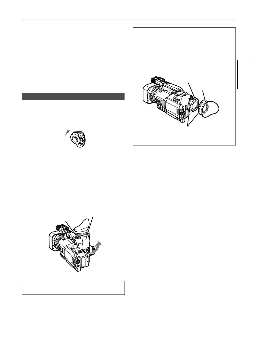
Fitting the eye cup
Attach the eye cup by aligning the projections
on the eye cup holder and eye cup and fitting
them together.
• Turning the eye cup after attaching it may cause
the eye cup holder to come off. If the eyecup
holder does come off, see “Cleaning the
Viewfinder” (Page 83) for details on how to refit it.
Eye cup holder
Eye cup
Projection
Preparations
Do not point the viewfinder at the sun.
Doing so may damage the parts inside.
23
Viewfinder (continued)
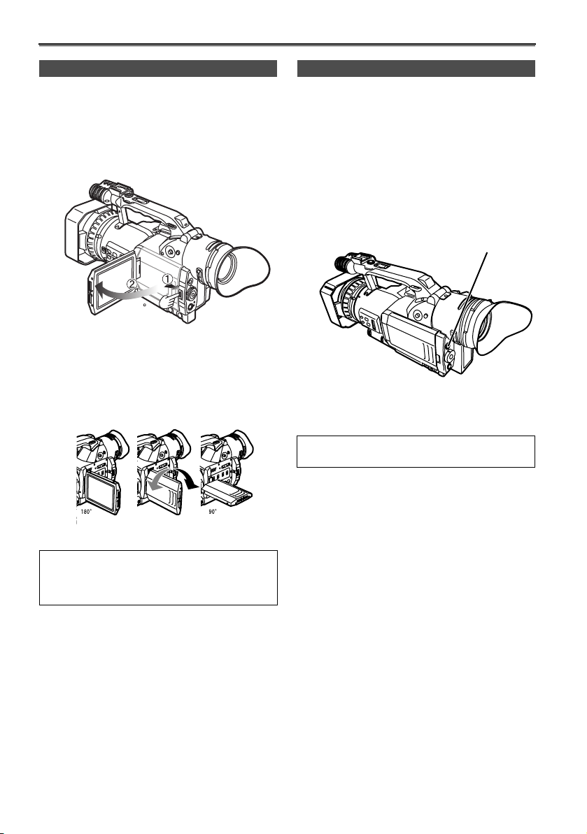
Using the LCD
1 Set the POWER switch to ON.
2 Press the OPEN button in the direction shown
by arrow (1) to open the LCD.
It can open out to 120 degrees. Do not try to
open it further as this will damage the camera.
120
3 Position the LCD monitor where it is easiest to
see.
• The monitor can be rotated 180° toward the
lens and 90° toward you.
• Do not apply unnecessary force to the open
LCD. This can damage the camera.
Emphasizing outlines
Emphasizing the outlines of the images you see in
the viewfinder or on the LCD makes it easier to
focus.
Emphasizing the outlines does not effect the
images you shoot.
1 In CAMERA mode, press EVF DTL/END
SEARCH.
• “EVF DTL ON” appears on the screen for
about 2 seconds.
EVF DTL/
END SEARCH button
Press EVF DTL/END SEARCH again to return
to the original display. “EVF DTL OFF” appears
on the screen for about 2 seconds.
EVF DTL/END SEARCH works differently when
in VCR mode. (Page 51)
• Ensure the LCD is fully closed.
• Both the LCD and viewfinder come on when you
have rotated the LCD to face in the same
direction as the lens for self-portrait shooting.
24
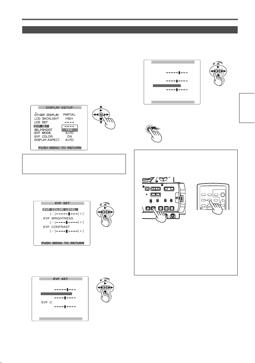
Adjusting the screen display
1 To adjust the viewfinder’s screen:
In the setup menus, DISPLAY SETUP screen
EVF SET, select YES.
To adjust the LCD’s screen:
In the setup menus, DISPLAY SETUP screen
LCD SET, select YES.
• For menu operation (Page 66)
• You can also use the menu buttons on the
remote control. (Page 19)
The following explanations show how to change
the viewfinder’s display. You can change the
LCD’s displays in the same way.
2 Select EVF COLOR LEVEL and move the
OPERATION lever t or y to adjust the
color level of the screen.
EVF SET
EVF COLOR LEVEL
_
[ ]
EVF BRIGHTNESS
_
[ ]
EVF CONTRAST
_
[ ]
PUSH MENU TO RETURN
[ + ]
[ + ]
[ + ]
3 Select EVF BRIGHTNESS and move the
OPERATION lever t or y to adjust the
brightness of the screen.
EVF SET
EVF COLOR LEVEL
_
[ ]
EVF BRIGHTNESS
_
[ ]
EVF CONTRAST
_
[ ]
[ + ]
[ + ]
[ + ]
4 Select EVF CONTRAST and move the
OPERATION lever t or y to adjust the
contrast of the screen.
EVF SET
EVF COLOR LEVEL
_
[ ]
EVF BRIGHTNESS
_
[ ]
EVF CONTRAST
_
[ ]
PUSH MENU TO RETURN
[ + ]
[ + ]
[ + ]
5 Press MENU three times to exit the menus.
MENU
• You can return the settings for EVF SET and LCD
SET to the factory settings by selecting the item
and pressing COUNTER RESET (if it is possible
to change the item at that time).
START/
DATE/
PHOTO
STOP
TIME
SHOT
OSD
COUNTER
RESET TITLE
REC A.DUB
PLAY/REW FF/
ZOOM
VOL +
-
MULTI/
P-IN-P
Camera or Remote control
• The viewfinder remains on when you open the
LCD if you have set the EVF MODE in the
DISPLAY SETUP screen to ON.
• The viewfinder display can be in color or black
and white. (See the setup menus, DISPLAY
SETUP screen, EVF COLOR.) The resolution is
the same for both of them.
Preparations
PUSH MENU TO RETURN
25
Time data
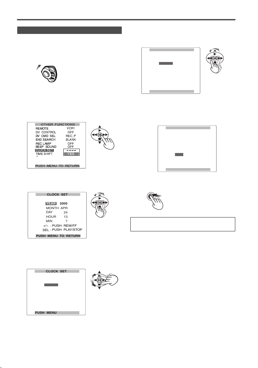
Setting the calendar
This shows you how to adjust the calendar to 5:20
PM on December 25, 2005.
1 Set the POWER switch to ON.
P
O
W
E
R
O
N
O
F
F
2 In the setup menus, OTHER FUNCTIONS
screen, CLOCK SET, select YES.
• For menu operation (Page 66)
• You can also use the menu buttons on the
remote control. (Page 19)
3 Move the OPERATION lever t or y to set
the year to 2005.
CLOCK SET
2005
YEAR
APR
MONTH
DAY
24
HOUR
13
MIN
-
+/
SEL
PUSH MENU TO RETURN
Choose a year between 2000 and 2089.
7
: PUSH REW/FF
: PUSH PLAY/STOP
5 Move the OPERATION lever t or y to set
the MONTH to DEC.
CLOCK SET
2005
YEAR
DEC
MONTH
DAY
24
HOUR
13
MIN
-
+/
SEL
PUSH MENU TO RETURN
7
: PUSH REW/FF
: PUSH PLAY/STOP
6 Set DAY, HOUR, and MIN using the method
shown in steps 4 and 5.
• This is a 24-hour clock.
CLOCK SET
2005
YEAR
DEC
MONTH
DAY
25
HOUR
17
20
MIN
+/
-
: PUSH REW/FF
: PUSH PLAY/STOP
SEL
PUSH MENU TO RETURN
7 Press MENU three times to exit the menus.
MENU
The clock can vary in accuracy so check that
the time is correct before shooting.
4 Move the OPERATION lever r to move to
MONTH.
CLOCK SET
2005
YEAR
APR
MONTH
DAY
24
HOUR
13
7
: PUSH REW/FF
: PUSH PLAY/STOP
26
MIN
-
+/
SEL
PUSH MENU TO RETURN
Recharging the built-in battery
The camera’s internal battery saves the date and
time. “ ” appears on the screen of the
viewfinder or LCD when the internal battery is
running low on charge.
Do the following to recharge it.
Reset the date and time when fully recharged.
1 Connect the AC adapter. (Page 10)
4 Press the OPERATION lever [h] (or move it
y), move it r to select YES and press [h]
again.
RECORDING SETUP
TC PRESET
UB MODE
UB PRESET
ONE-SHOT REC
REC TIME
- - - -
USER
YES
0.5
S
2 Leave the POWER switch at OFF.
3 Leave the camera-recorder like this for about 4
hours.
• The internal battery charges during this time.
• Recharge the battery regularly to ensure
correct TC and menu operations.
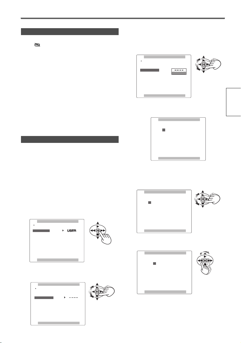
Setting user information
Setting user information allows you to store 8-digit
information (such as the date and time) in the
hexadecimal format on the tape’s sub code track.
User information is automatically saved in the
memory and retained after you turn off the power.
1 Set the POWER switch to ON.
2 In the setup menus, RECORDING SETUP
screen UB MODE, select USER.
• For menu operation (Page 66)
• You can also use the menu buttons on the
remote control. (Page 19)
RECORDING SETUP
TC PRESET
UB MODE
UB PRESET
ONE-SHOT REC
REC TIME
PUSH MENU TO RETURN
- - - -
- - - -
OFF
0.5
S
3 Move the OPERATION lever r to select UB
PRESET.
RECORDING SETUP
TC PRESET
UB MODE
UB PRESET
ONE-SHOT REC
REC TIME
- - - -
USER
OFF
0.5
S
PUSH MENU TO RETURN
5 The following screen appears, so use the
OPERATION lever to set the user information.
UB PRESET
0 0 0 0 0 0 0 0
+/
-
: PUSH PLAY/STOP
SEL
: PUSH REW/FF
PUSH MENU TO RETURN
Move the OPERATION lever e or r to select
the characters for the user information.
• You can use numbers from 0 to 9 and letters
from A to F.
UB PRESET
F 0 0 0 0 0 0 0
+/
-
: PUSH PLAY/STOP
SEL
: PUSH REW/FF
PUSH MENU TO RETURN
Move the OPERATION lever t or y to
move to the next digit.
UB PRESET
F 0 0 0 0 0 0 0
+/
-
: PUSH PLAY/STOP
SEL
: PUSH REW/FF
PUSH MENU TO RETURN
Preparations
PUSH MENU TO RETURN
27
 Loading...