

Panasonic DVOP001 User Manual
English
5. Options
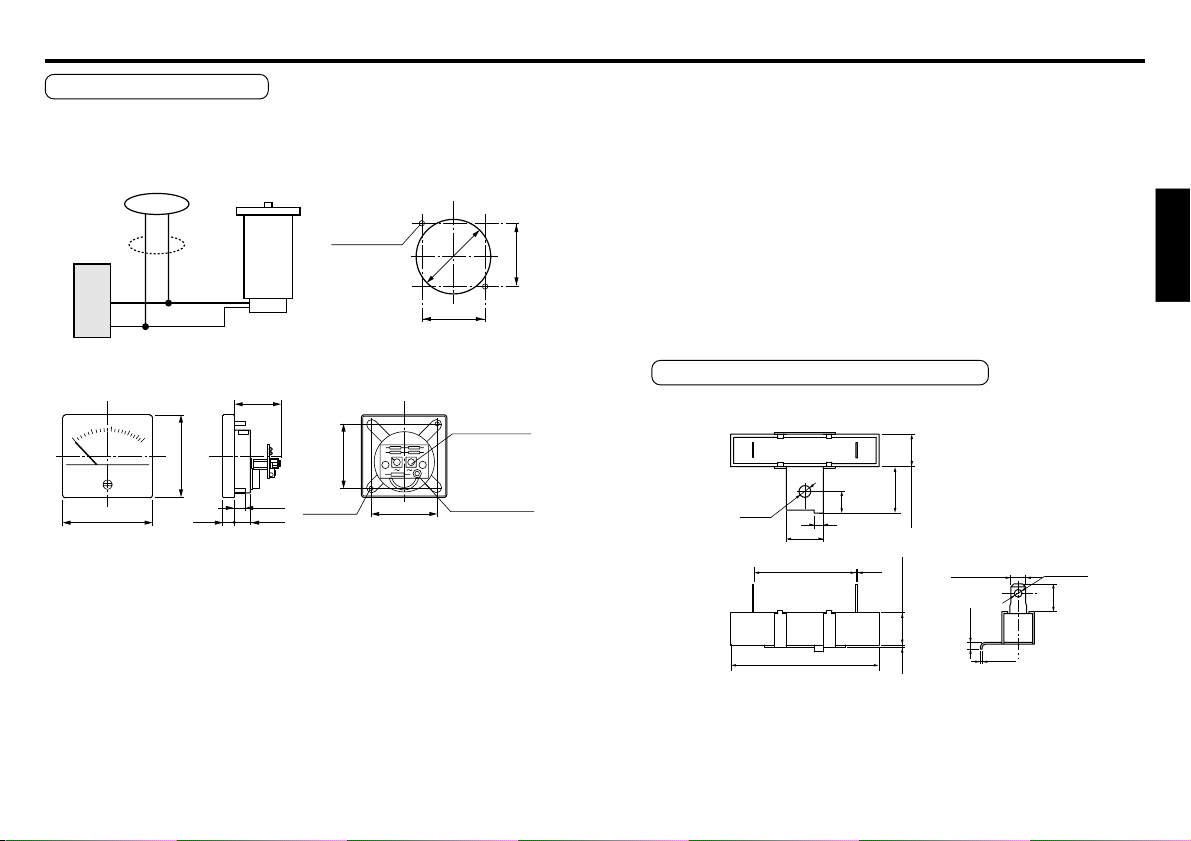
Tachometer (DVOP001)
This tachometer is especially designed to operate with our speed
controller so that it can provide easier displaying of motor speed.
TM
2–ø3.5 hole
48
2–M3
Mounting
screw
ø54
48 ±0.3
Panel cutout drawing
48
4
5
Speed controller
Pin No.
65
Motor
Pink
Pink
TG
max40
60
8 ±1
8.5
12.2
<Precautions>
· Connect the tachometer in parallel with the tachometer generator (TG).
· If the tachometer (TM) requires longer connection cable, use shielded
twisted pair cable. Don't ground shielding of the cable.
· Accuracy of tachometer readings will depend on variation in motor
performance and operating environment (temperature and noise). The
tachometer should be used as a rough indicator.
Unit: mm
±1
48 ±0.3
Input terminal
Potentiometer
for calibration
<Note>
Calibrate the scale of the tachometer (TM) from the potentiometer on
the rear panel.
1. While running the motor at its full rotation speed without load,
adjust to 1450 min-1 if power supply is at 50 Hz, or 1750 min-1 if
60 Hz.
2. Monitor the output signal of the TG on an oscilloscope and
determine the frequency. And adjust:
rotating speed N (min-1) = 5 x f (Hz)
Caution: Since the circuit is not isolated from the power supply,
use an insulated tool such as an insulated screwdriver to protect
against electric shock.
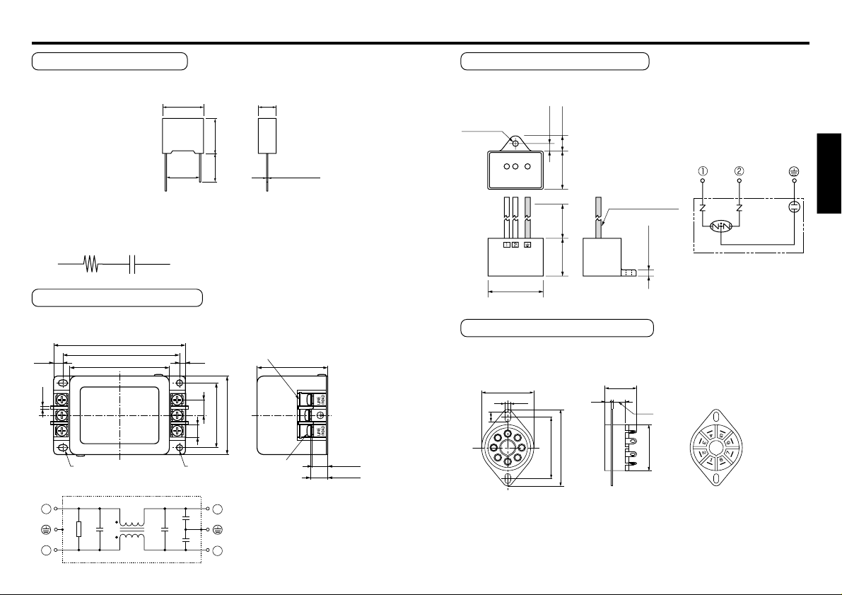
External braking resistor (DVOP003)
5.6 Ω 10W
Unit: mm
14 ±1
ø3.8
33 ±3.0 0.5
48 ±2
6 ±0.5
3
12
1.5
±
10.5
0.8
10.5 ±1.5
4.8 ±0.5
(2.2)
(0.6)
(ø2.5)
3
+
9
–1
<Precautions>
The resistance of DVOP003 is 5.6 Ω. When using commercially available
resistor, choose 4.7-6.8 Ω, 10 W or larger.
– 29 –– 28 –
English
<Circuit diagram>
ø4.2 ±0.2
41 ±1
UL-1015 AWG16
28 ±1
5.5 ±1
11 ±1
28.5 ±1
4.5 ±0.5
200
+30
–0
Unit: mm
39 ±0.1
ø29
48.4
6
33
20.8
4
8.0
0.8
3.2
Unit: mm
5. Options
Spark killer (DVOP008)
0.1 µ F 120 Ω
<Precautions>
20.5 ±0.5
16.5 ±1
9 ±0.5
ø0.7 ±0.05
14.3min 17.5 ±0.5
The capacitance of capacitor in the DVOP008 is 0.1 F and the
resistance of the internal resistor is 120 Ω. When using commercially
available spark killer, choose one consisting of the following parts:
R1 C1
R1 = 10 – 200 Ω (1/4 W or larger)
C1 = 0.1 – 0.33 µF (AC250WV)
Noise filter (DVOP3611-5)
Type SUP-EQ5-ER-6: Okaya Electric Industries Co., Ltd.
100.0 ±2.0
7.0
<Circuit diagram>
2.0
1
2
88.0
75.0
Marking
(label)
R
Cx Cx
L
5.0
2–ø4.52–ø4.5 x 6.75
Cy
Cy
10.0
12.0
50.0
3
4
Terminal cover (clear)
53.1 ±1.0
60.0
6-M4
Unit: mm
Unit: mm
(
11.6
)
13.0
)
(
Surge absorber (DVOP4190)
Type R.A.V-781BWZ-4: Okaya Electric Industries Co., Ltd.
Octal pin socket (DVOP4560)
Type S-3898: Sato Parts Co., Ltd.
– 31 –– 30 –
 Loading...