

Panasonic DMC-FT5EP, DMC-FT5EE, DMC-FT5GC, DMC-FT5GA, DMC-FT5GN Service Manual
...
© Panasonic Corporation 2013.
Unauthorized copying and distribution is a violation
of law.
ORDER NO.DSC1304010CE
B26
Digital Camera
Model No. DMC-FT5EB
DMC-FT5EE
DMC-FT5EF
DMC-FT5EG
DMC-FT5EP
DMC-FT5GC
DMC-FT5GA
DMC-FT5GN
DMC-FT5EA
DMC-TS5P
DMC-TS5PC
DMC-TS5PU
DMC-TS5GH
DMC-TS5GT
DMC-TS5GD
Colours
(A)....................Blue Type (Except DMC-FT5EE/EA,
DMC-TS5GH/GT/GD)
(D)....................Orange Type
(S)....................Silver Type (Except DMC-FT5EF/EA,
DMC-TS5PC/PU)
(K)....................Black Type (Except DMC-FT5EE/GN/EA,
DMC-TS5PC/GH/GT/GD)

2
TABLE OF CONTENTS
PAGE PAGE
1 Safety Precautions -----------------------------------------------3
1.1. General Guidelines ----------------------------------------3
1.2. Leakage Current Cold Check ---------------------------3
1.3. Leakage Current Hot Check (See Figure 1)---------3
1.4. How to Discharge the Capacitor on Flash
P.C.B.----------------------------------------------------------4
2Warning--------------------------------------------------------------5
2.1. Prevention of Electrostatic Discharge (ESD)
to Electrostatic Sensitive (ES) Devices---------------5
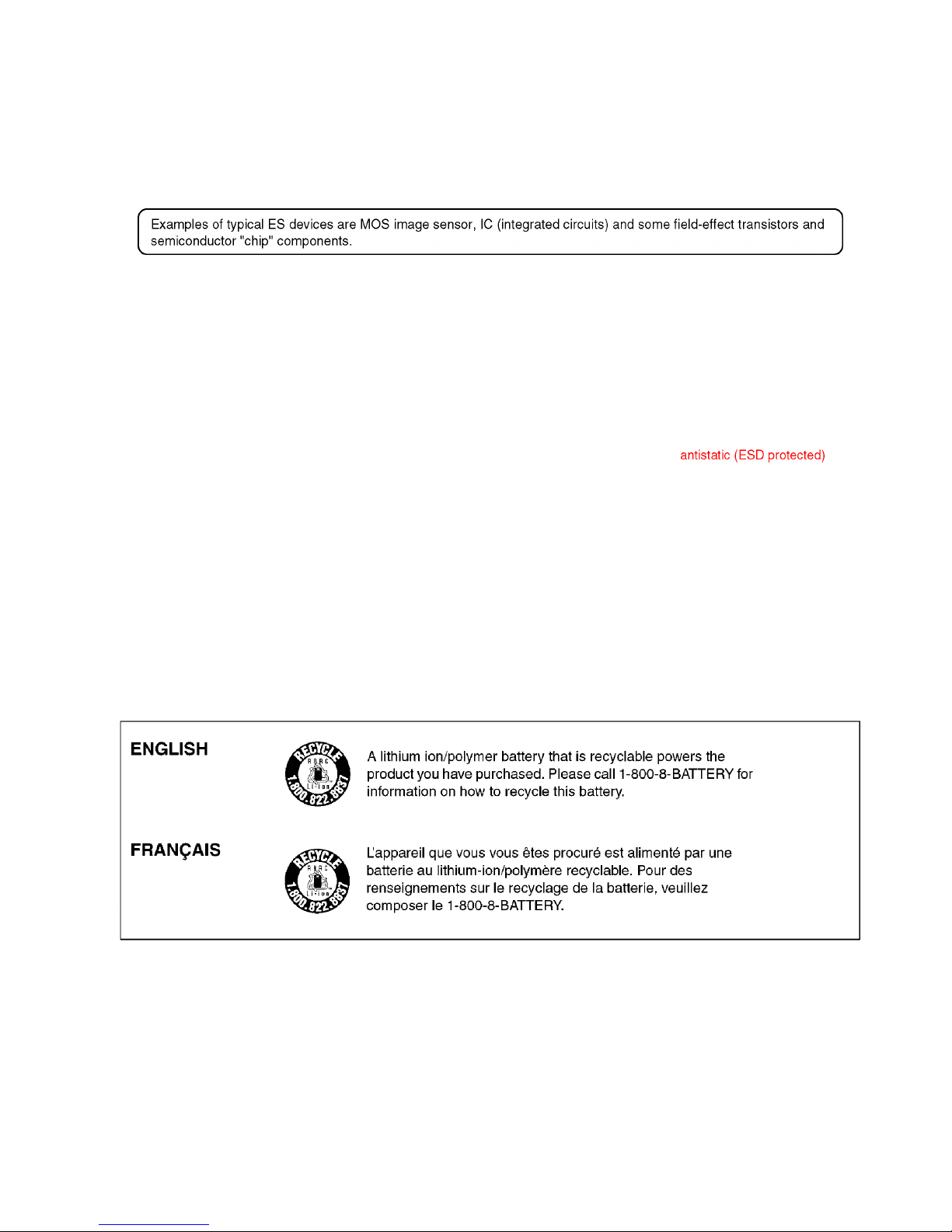
2.2. How to Recycle the Lithium Ion Battery (U.S.
Only)-----------------------------------------------------------5
2.3. Caution for AC Cord (For EB/GC/GH)----------------6
2.4. How to Replace the Lithium Battery-------------------7
3 Service Navigation------------------------------------------------9
3.1. Introduction --------------------------------------------------9
3.2. Service Navigation-----------------------------------------9
3.3. Service Notes ---------------------------------------------11
3.4. General Description About Lead Free Solder
(PbF) --------------------------------------------------------12
3.5. How to Define the Model Suffix (NTSC or PAL
model)-------------------------------------------------------13
4 Specifications----------------------------------------------------17
5 Location of Controls and Components------------------18
6 Service Mode -----------------------------------------------------19
6.1. Error Code Memory Function ------------------------- 19
7 Troubleshooting Guide----------------------------------------23
7.1. Service and Check Procedures (Air-leak Test)--- 23
7.2. Failure Diagnosis of GPS ------------------------------27
7.3. Checking Method of compass, altimeter, &
barometer --------------------------------------------------28
7.4. Failure Diagnosis of Wi-Fi------------------------------32
7.5. Failure Diagnosis of NFC ------------------------------33
8 Service Fixture & Tools---------------------------------------34
8.1. Service Fixture and Tools ------------------------------34
8.2. When Replacing the Main P.C.B. --------------------35
8.3. Service Position ------------------------------------------35
9 Disassembly and Assembly Instructions---------------36
9.1. Disassembly Flow Chart--------------------------------36
9.2. P.C.B. Location -------------------------------------------36
9.3. Disassembly Procedures-------------------------------37
10 Measurements and Adjustments --------------------------48
10.1. Introduction ------------------------------------------------48
10.2. Before Disassembling the unit------------------------48
10.3. Details of Electrical Adjustment-----------------------50
10.4. After Adjustment------------------------------------------54
11 Maintenance ------------------------------------------------------55
11.1. Cleaning Lens and LCD Panel -----------------------55
12 Block Diagram ---------------------------------------------------57
12.1. Overall Block Diagram----------------------------------57
12.2. System Control Block Diagram-----------------------58
12.3. Video/Audio Signal Process Block Diagram-------59
12.4. Lens Drive Block Diagram -----------------------------60
12.5. Power Block Diagram-----------------------------------61
13 Wiring Connection Diagram---------------------------------62
13.1. Interconnection Schematic Diagram ----------------62
3
1 Safety Precautions
1.1. General Guidelines
1. IMPORTANT SAFETY NOTICE
There are special components used in this equipment
which are important for safety . These parts are marked by
in the Schematic Diagrams, Circuit Board Layout,
Exploded Views and Replacement Parts List. It is
essential that these critical parts should be replaced with
manufacturer's specified parts to prevent X-RADIATION,
shock fire, or other hazards. Do not modify the original
design without permission of manufacturer.
2. An Isolation Transformer should always be used during
the servicing of AC Adaptor whose chassis is not isolated
from the AC power line. Use a transformer of adequate
power rating as this protects the technician from
accidents resulting in personal injury from electrical
shocks. It will also protect AC Adaptor from being
damaged by accidental shorting that may occur during
servicing.
3. When servicing, observe the original lead dress. It a short
circuit is found, replace all parts which have been
overheated or damaged by the short circuit.
4. After servicing, see to it that all the protective devices
such as insulation barriers, insulation papers shields are
properly installed.
5. After servicing, make the following leakage current
checks to prevent the customer from being exposed to
shock hazards.
1.2. Leakage Current Cold Check
1. Unplug the AC cord and connect a jumper between the
two prongs on the plug.
2. Measure the resistance value, with an ohmmeter,
between the jumpered AC plug and each exposed
metallic cabinet part on the equipment such as
screwheads, connectors, control shafts, etc. When the
exposed metallic part has a return path to the chassis, the
reading should be between 1MΩ and 5.2MΩ. When the
exposed metal does not have a return path to the chassis,
the reading must be infinity.
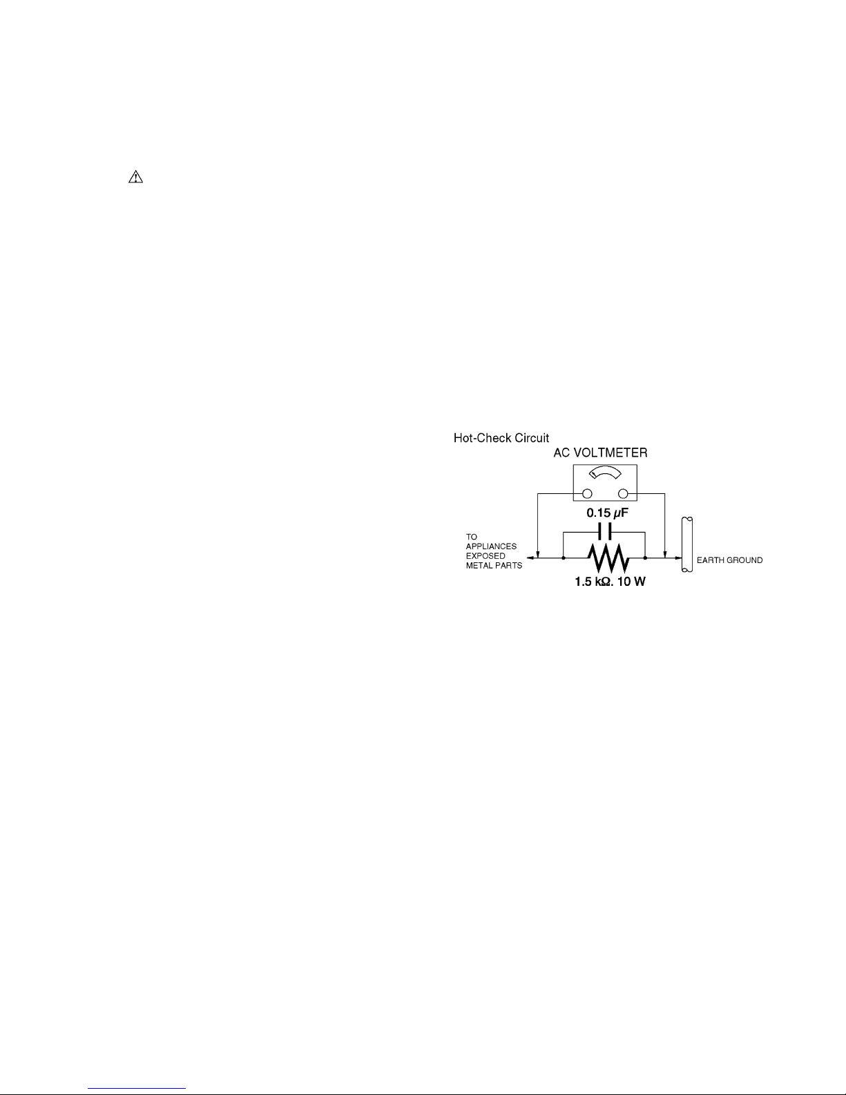
1.3. Leakage Current Hot Check
(See Figure 1)
1. Plug the AC cord directly into the AC outlet. Do not use
an isolation transformer for this check.
2. Connect a 1.5kΩ, 10 W resistor, in parallel with a 0.15μF
capacitor, between each exposed metallic part on the set
and a good earth ground, as shown in Figure 1.
3. Use an AC voltmeter, with 1 kΩ/V or more sensitivity , to
measure the potential across the resistor.
4. Check each exposed metallic part, and measure the
voltage at each point.
5. Reverse the AC plug in the AC outlet and repeat each of
the above measurements.
6. The potential at any point should not exceed 0.75 V RMS.
A leakage current tester (Simpson Model 229 or
equivalent) may be used to make the hot checks, leakage
current must not exceed 1/2 mA. In case a measurement
is outside of the limits specified, there is a possibility of a
shock hazard, and the equipment should be repaired and
rechecked before it is returned to the customer.
Figure 1
4
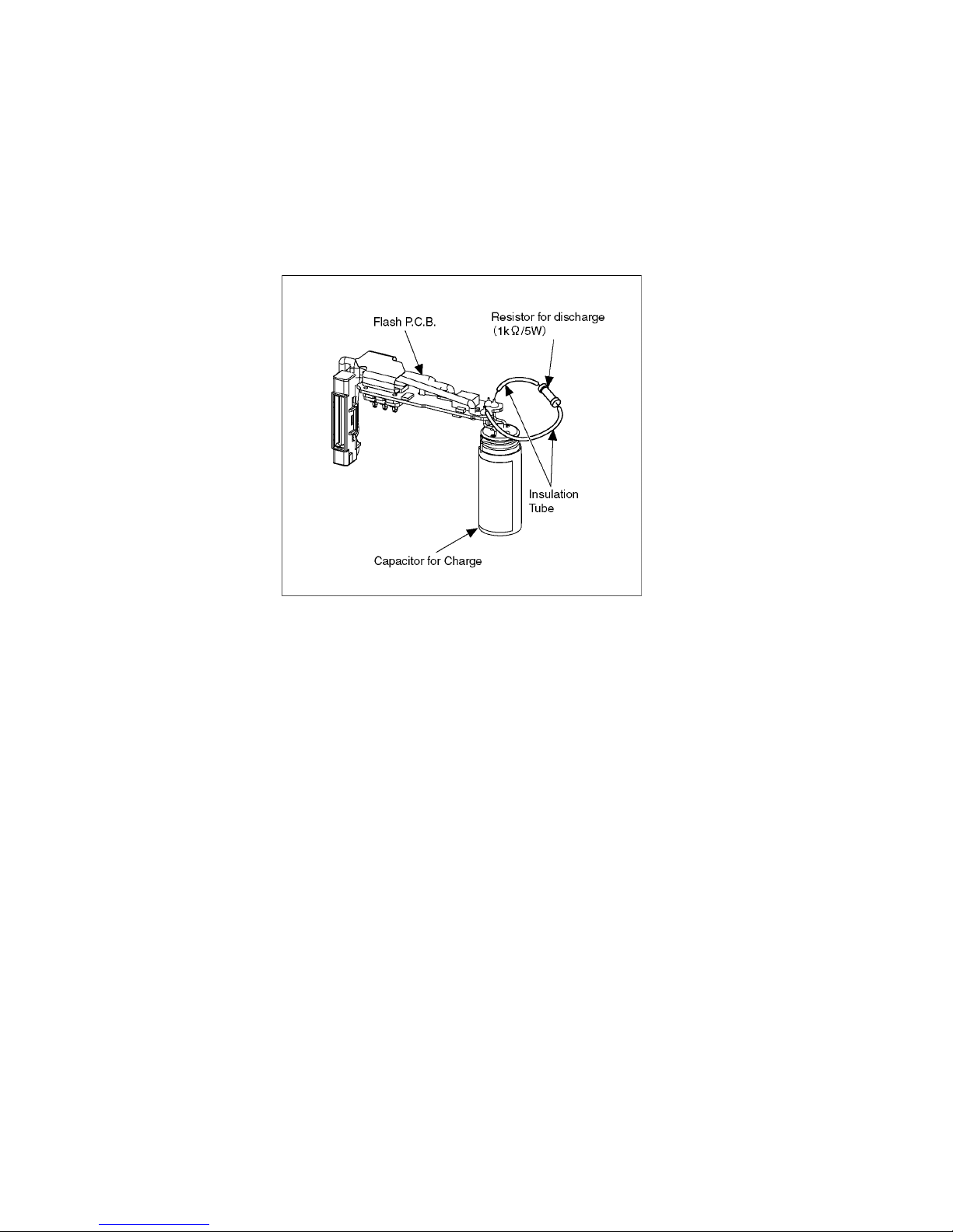
1.4. How to Discharge the Capacitor on Flash P.C.B.
CAUTION:
1. Be sure to discharge the capacitor on Flash P.C.B.
2. Be careful of the high voltage circuit on Flash P.C.B. when servicing.
[Discharging Procedure]
1. Refer to the disassemble procedure and remove the necessary parts/unit.
2. Put the insulation tube onto the lead part of Resistor (ERG5SJ102:1kΩ /5W).
(An equivalent type of resistor may be used.)
3. Put the resistor between both terminals of capacitor on Flash P.C.B. for approx. 5 seconds.
4. After discharging confirm that the capacitor voltage is lower than 10V using a voltmeter.
Fig. F1
5
2Warning
2.1. Prevention of Electrostatic Discharge (ESD) to Electrostatic Sensitive
(ES) Devices
Some semiconductor (solid state) devices can be damaged easily by static electricity. Such components commonly are called
Electrostatically Sensitive (ES) Devices.
The following techniques should be used to help reduce the incidence of component damage caused by electrostatic discharge
(ESD).
1. Immediately before handling any semiconductor component or semiconductor-equipped assembly , drain off any ESD on your
body by touching a known earth ground. Alternatively, obtain and wear a commercially available discharging ESD wrist strap,
which should be removed for potential shock reasons prior to applying power to the unit under test.
2. After removing an electrical assembly equipped with ES devices, place the assembly on a conductive surface such as
aluminum foil, to prevent electrostatic charge buildup or exposure of the assembly.
3. Use only a grounded-tip soldering iron to solder or unsolder ES devices.
4. Use only an antistatic solder removal device. Some solder removal devices not classified as can
generate electrical charge sufficient to damage ES devices.
5. Do not use freon-propelled chemicals. These can generate electrical charges sufficient to damage ES devices.
6. Do not remove a replacement ES device from its protective package until immediately before you are ready to install it. (Most
replacement ES devices are packaged with leads electrically shorted together by conductive foam, aluminum foil or
comparable conductive material).
7. Immediately before removing the protective material from the leads of a replacement ES device, touch the protective material
to the chassis or circuit assembly into which the device will be installed.
CAUTION:
Be sure no power is applied to the chassis or circuit, and observe all other safety precautions.
8. Minimize bodily motions when handling unpackaged replacement ES devices. (Otherwise harmless motion such as the
brushing together of your clothes fabric or the lifting of your foot from a carpeted floor can generate static electricity (ESD)
sufficient to damage an ES device).
2.2. How to Recycle the Lithium Ion Battery (U.S. Only)
6
2.3. Caution for AC Cord (For EB/
GC/GH)
2.3.1. Information for Your Safety
IMPORTANT
Your attention is drawn to the fact that recording of prerecorded tapes or discs or other published or broadcast
material may infringe copyright laws.
WARNING
To reduce the risk of fire or shock hazard, do not expose
this equipment to rain or moisture.
CAUTION
To reduce th e risk of fi re or shock hazard and annoying
interference, use the recommended accessories only.
FOR YOUR SAFETY
DO NOT REMOVE THE OUTER COVER
To prevent electric shock, do not remove the cover. No user
serviceable parts inside. Refer servicing to qualified service
personnel.
2.3.2. Caution for AC Mains Lead
For your safety, please read the following text carefully.
This appliance is supplied with a moulded three-pin mains plug
for your safety and convenience.
A 5-ampere fuse is fitted in this plug.
Should the fuse need to be replaced please ensure that the
replacement fuse has a rating of 5 amperes and it is approved
by ASTA or BSI to BS1362
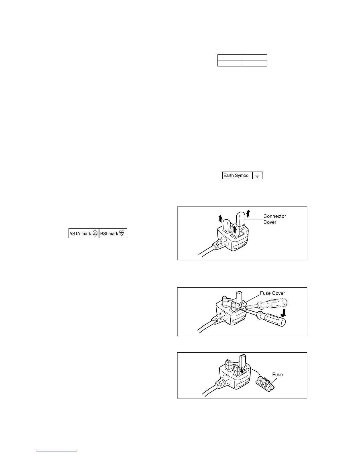
Check for the ASTA mark or the BSI mark on the body of the
fuse.
If the plug contains a removable fuse cover you must ensure
that it is refitted when the fuse is replaced.
If you lose the fuse cover, the plug must not be used until a
replacement cover is obtained.
A replacement fuse cover can be purchased from your local
Panasonic Dealer.
If the fitted moulded plug is unsuitable for the socket outlet in
your home then the fuse should be removed and the plug cut
off and disposed of safety.
There is a danger of severe electrical shock if the cut off plug is
inserted into any 13-ampere socket.
If a new plug is to be fitted please observe the wiring code as
shown below.
If in any doubt, please consult a qualified electrician.
2.3.2.1. Important
The wires in this mains lead are coloured in accordance with
the following code:
As the colours of the wires in the mains lead of this appliance
may not correspond with the coloured markings identifying the
terminals in your plug, proceed as follows:
The wire which is coloured BLUE must be connected to the
terminal in the plug which is marked with the letter N or
coloured BLACK.
The wire which is coloured BROWN must be connected to the
terminal in the plug which is marked with the letter L or coloured
RED.
Under no circumstances should either of these wires be
connected to the earth terminal of the three pin plug, marked
with the letter E or the Earth Symbol.
2.3.2.2. Before Use
remove the Connector Cover as follows.
2.3.2.3. How to Replace the Fuse
1. Remove the Fuse Cover with a screwdriver.
2. Replace the fuse and attach the Fuse cover.
Blue Neutral
Brown Live
7
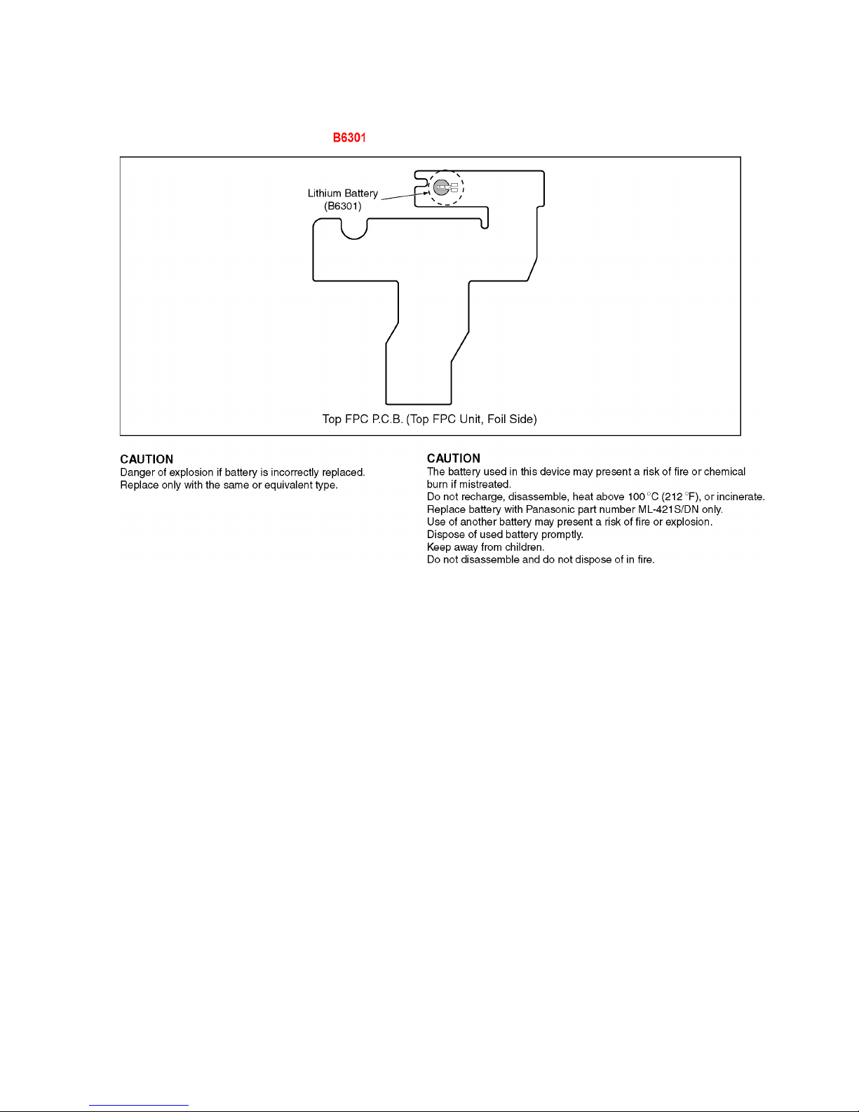
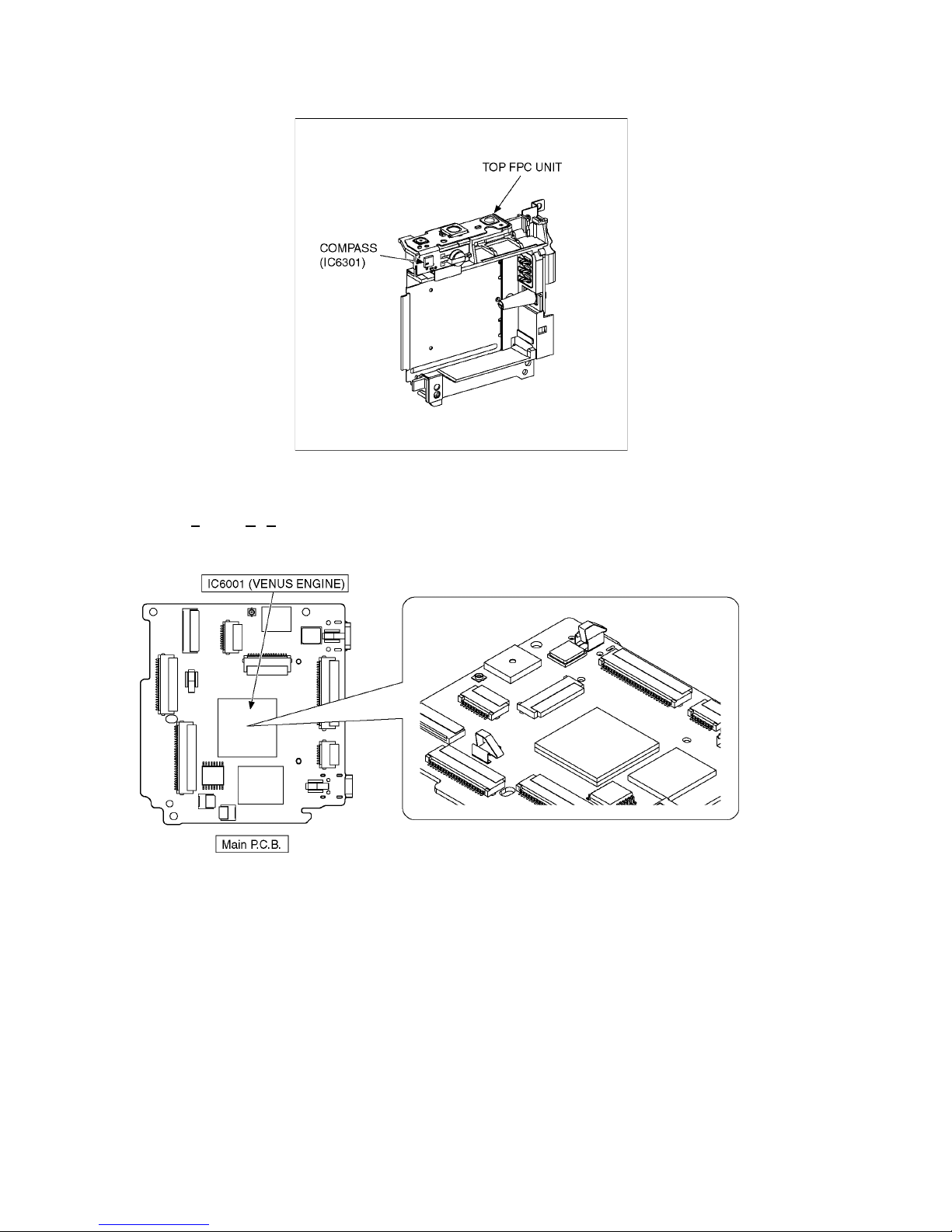
2.4. How to Replace the Lithium Battery
2.4.1. Replacement Procedure
1. Remove the Top FPC P.C.B. (Top FPC Unit) (Refer to Disassembly Procedures.)
2. Unsolder the Lithium battery (Ref. No. at foil side of Top FPC P.C.B. (Top FPC Unit)) and then replace it into new one.
Note:
The lithium battery is a critical component.
(Type No.: ML-421S/DN Manufactured by Ene r gy Co mpany, Panasonic Corporation)
It must never be subjected to excessive heat or discharge.
It must therefore only be fitted in equipment designed specifically for its use.
Replacement batteries must be of the same type and manufacture.
They must be fitted in the same manner and location as the original battery, with the correct polarity contacts observed.
Do not attempt to re-charge the old battery or re-use it for any other purpose.
It should be disposed of in waste products destined for burial rather than incineration.
8
Note:
Above caution is applicable for a battery pack which is for DMC-FT5 and DMC-TS5 series, as well.
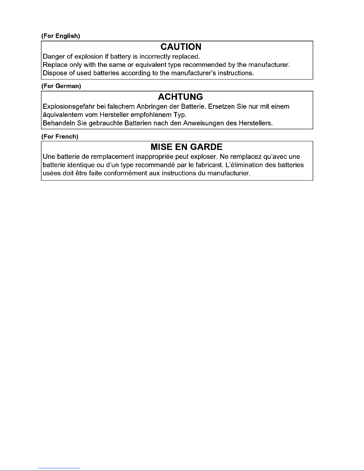
Danger of explosion if battery is incorrectly replaced.
Replace only with the same or equivalent type recommended by the manufacturer.
Dispose of used batteries according to the manufacturer's instructions.
9
3 Service Navigation
3.1. Introduction
This service manual contains technical information, which will allow service personnel's to understand and service this model.
Please place orders using the parts list and not the drawing reference numbers.
If the circuit is changed or modified, the information will be followed by service manual to be controlled with original service manual.
3.2. Service Navigation
3.2.1. Air-leak test (inspection)
This does not guarantee no destruction, no malfunction, or waterproofing in all conditions.
*1 This means that the camera can be used underwater for specified time in specified pressure in accordance with the handling
method established by Panasonic.
*2 "MIL-STD 810F Method 516.5-Shock" is the test method standard of the U.S. Defense Department, which specifies
performing drop tests from a height of 122 cm (4.0 feet), at 26 orientations (8 corners, 12 ridges, 6 faces) using 5 sets of
devices, and passing the 26 orientation drops within 5 devices. (If failure occurs during the test, a new set is used to pass the
drop orientation test within a total of 5 devices)
Panasonic’s test method is based on the above "MIL-STD 810F Method 516.5-Shock". However, the drop height was changed
from 122 cm (4.0 feet) to 200 cm (6.6 feet) dropping onto 3 cm (0.10 feet) thick plyboard. This drop test was passed.
(Disregarding appearance change such as loss of paint or distortion of the part where drop impact is applied.)
*3 According to the test conditions specified by Panasonic.
• Due to the above characteristics of the products, perform the air-leak test (inspection) using Air -leak tester (Part No.:RFKZ0528)
before/after servicing including assembly and/or assembly process.
Note:
The purpose of the air-leak test before servicing is that whether the malfunction occurred due to air-leak or not.
• When servicing, refer to the "7.Troubleshooting Guide" section for details.
3.2.2. Replacing the waterproof packing (waterproof seal)
• The integrity of the waterproof packing may decrease about 1 year, with use and age.
• (We recommend end users to replace the waterproof packing (waterproof seal) at least once each year described in the
operating instructions.)
• As for replacement procedure, refer to the 7.1.2. Periodical maintenance (Packing replacement) flow for details.
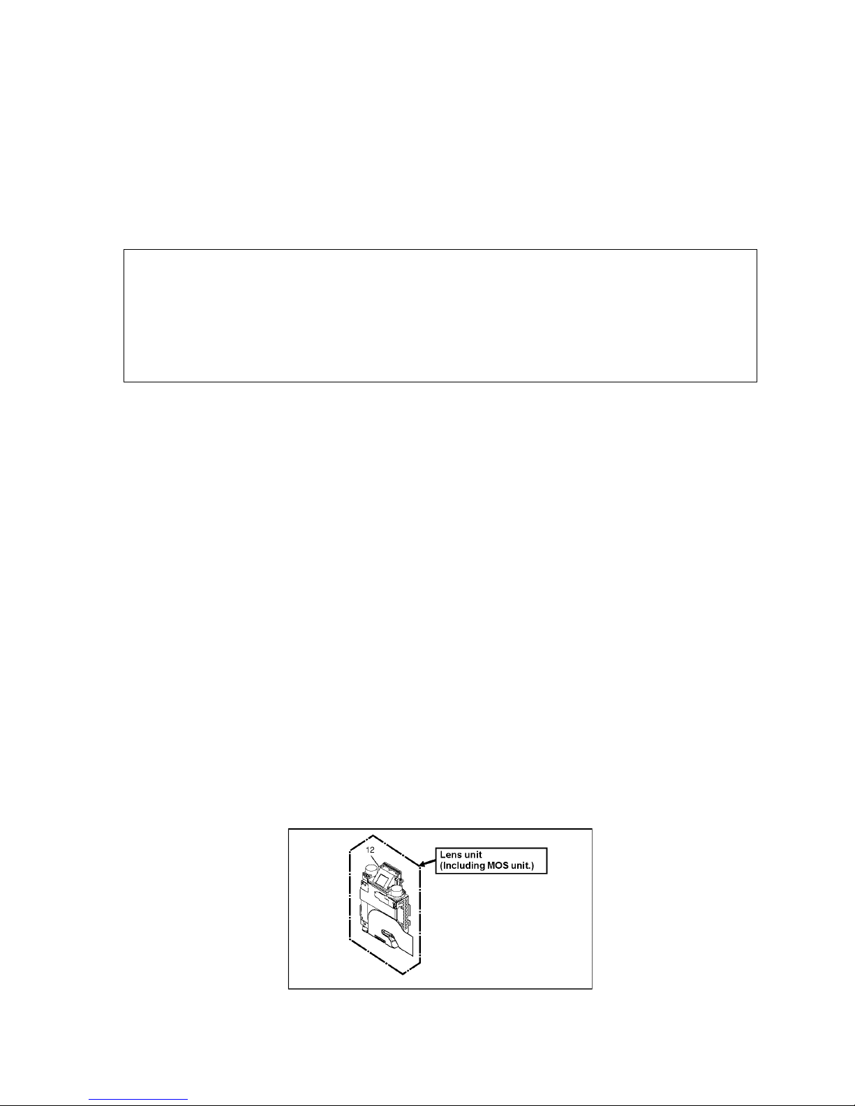
3.2.3. Lens Unit
• Since the lens unit for this model is assembled with high accuracy manufacturing technologies, it is not allowed to disassemble/
assemble the lens unit, in terms of performance retention.
When servicing, it has to be handled the "Lens with MOS unit" as the smallest part size.
Confirm the replacement part list and exploded views for details.
Waterproof/Dustproof Performance
This camera's waterproof/dustproof rating complies with the "IPX8" and "IP6X" ra tings. Provided the care and maintenance guidelines
described in this document are strictly followed, this camera can operate underwater, to a depth not exceeding 13 m (43 feet) for a time
not exceeding 60 minutes. (*1)
Anti-shock Performance
This camera also complies with "MIL-STD 810F Method 516.5-Shock". The camera has cleared a drop test from a height of 2 m (6.6
feet) onto 3 cm (0.10 feet) thick plywood. In most cases th is camera should not sustain any damage if dropped from a height not
exceeding 2 m (6.6 feet). (*2)
Withstand Load Performance
This camera complies with 100 kgf/220.5 lbf load tests. (*3)
10
3.2.4. About IC6301 (COMPASS) [On the TOP FPC UNIT]
When IC6301 is defects and necessary to be replaced, replace with whole TOP FPC UNIT as a unit.
3.2.5. About VENUS ENGINE (IC6001) < Located on the Main P.C.B. >
• The VENUS ENGINE (IC6001) consists of two IC chips, which are fixed together with solder.
(It is so called, "P
ackage On Package" type of IC.)
Caution:
• During servicing, do not press down hard on the surface of IC6001.
11
3.3. Service Notes
The page number in the section does not show the page number of this service manual.
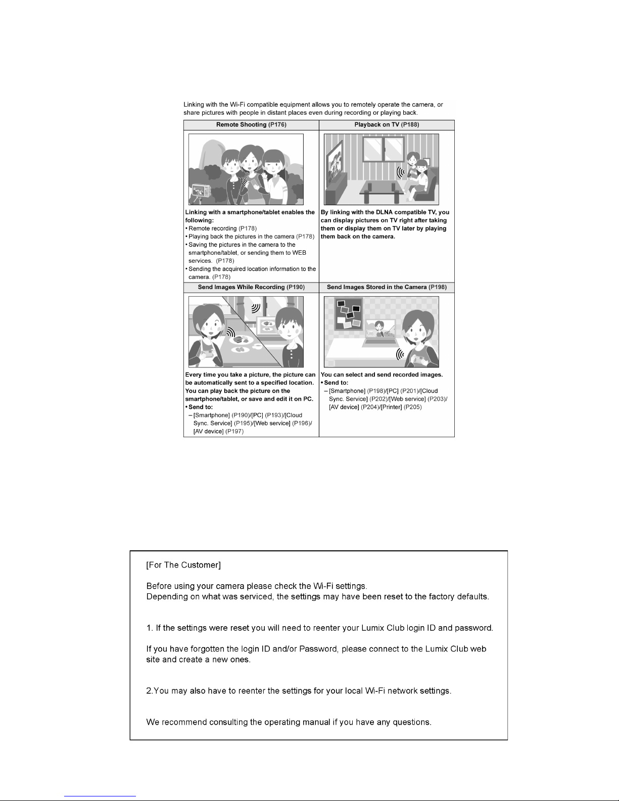
3.3.1. About Wi-Fi Function
3.3.2. Important Notice of Servicing
This Camera unit has the personal information of wireless LAN connection the customer has registered.
For the protection of private information, please erase the personal information af ter the com pletion of repair by "INITIAL
SETTING".
In addition, please print out the following documents, and pass to the customer with the Camera unit.
Printing Material [Leaflet for Customer]
Printing Material [Leaflet for Customer]

12
3.4. General Description About Lead Free Solder (PbF)
The lead free solder has been used in the mounting process of all electrical components on the printed circuit boards used for this
equipment in considering the globally environmental conservation.
The normal solder is the alloy of tin (Sn) and lead (Pb). On the other hand, the lead free solder is the alloy mainly consists of tin
(Sn), silver (Ag) and Copper (Cu), and the melting point of the lead free solder is higher approx.30 °C (86 °F) more than that of the
normal solder.
Definition of P.C.B. Lead Free Solder being used
Service caution for repair work using Lead Free Solder (PbF)
• The lead free solder has to be used when repairing the equipment for which the lead free solder is used.
• (Definition: The letter of is printed on the P.C.B. using the lead free solder.)
• To put lead free solder, it should be well molten and mixed with the original lead free solder.
• Remove the remaining lead free solder on the P.C.B. cleanly for soldering of the new IC.
• Since the melting point of the lead free solder is higher than that of the normal lead solder, it takes the longer time to melt the
lead free solder.
• Use the soldering iron (more than 70W) equipped with the temperature control after setting the temperature at 350±30 degrees
C (662±86 °F).
Recommended Lead Free Solder (Service Parts Route.)
• The following 3 types of lead free solder are available through the service parts route.
RFKZ03D01KS-----------(0.3mm 100g Reel)
RFKZ06D01KS-----------(0.6mm 100g Reel)
RFKZ10D01KS-----------(1.0mm 100g Reel)
Note
* Ingredient: tin (Sn) 96.5%, silver (Ag) 3.0%, Copper (Cu) 0.5%, Cobalt (Co) / Germanium (Ge) 0.1 to 0.3%
The letter of is printed either foil side or components side on the P.C.B. using the lead free solder.
(See right figure)
13
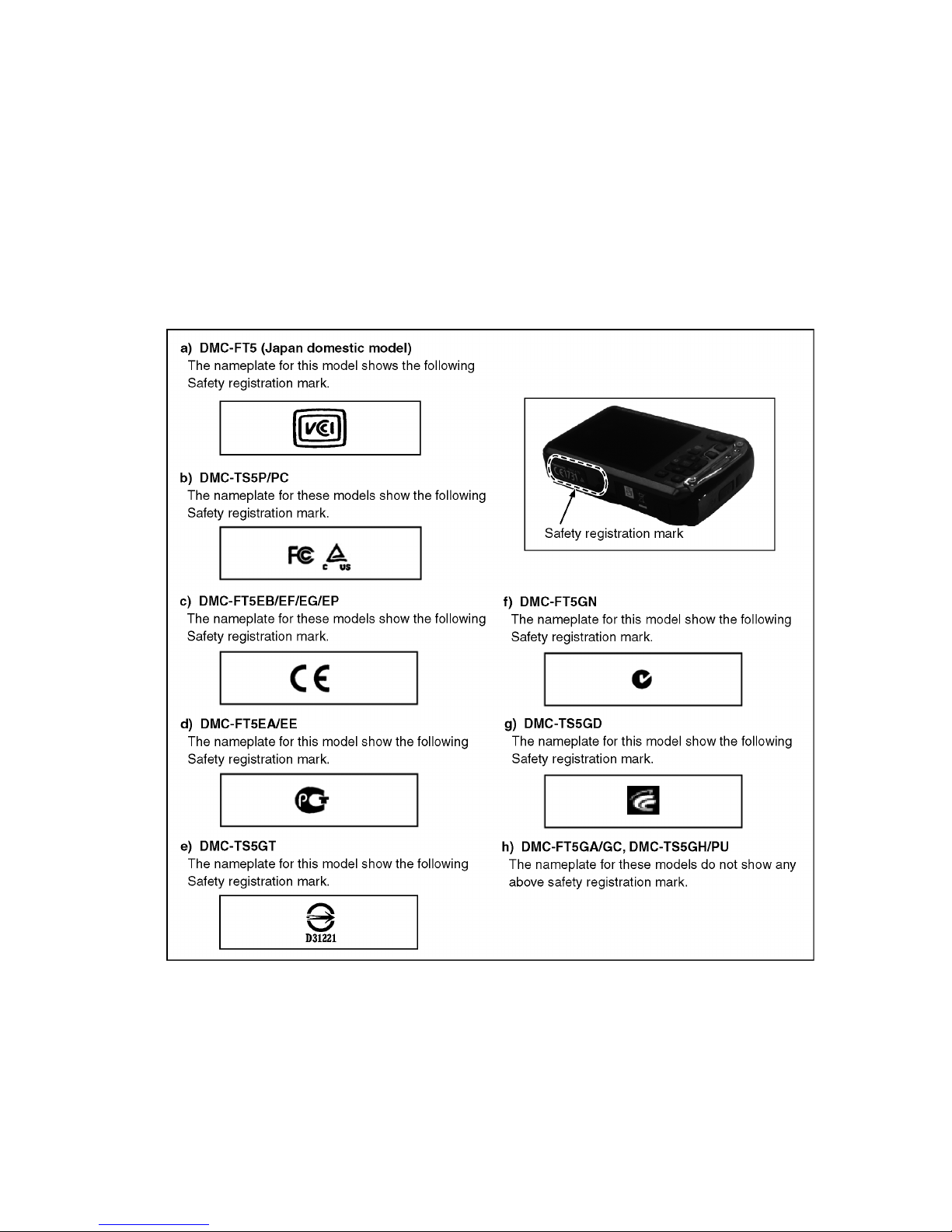
3.5. How to Define the Model Suffix (NTSC or PAL model)
There are eight kinds of DMC-FT5/TS5, regardless of the colours.
• a) DMC-FT5 (Japan domestic model.)
• b) DMC-TS5P/PC
• c) DMC-FT5EB/EF/EG/EP
• d) DMC-FT5EA/EE
• e) DMC-TS5GT
• f) DMC-FT5GN
• g) DMC-TS5GD
• h) DMC-FT5GA/GC, DMC-TS5GH/PU
What is the difference is that the "INITIAL SETTINGS" data which is stored in Flash ROM mounted on Main P.C.B.
3.5.1. Defining methods
To define the model suffix to be serviced, refer to the nameplate which is putted on the bottom side of the Unit.
Note:
After replacing the Main P.C.B., be sure to achieve adjustment.
14
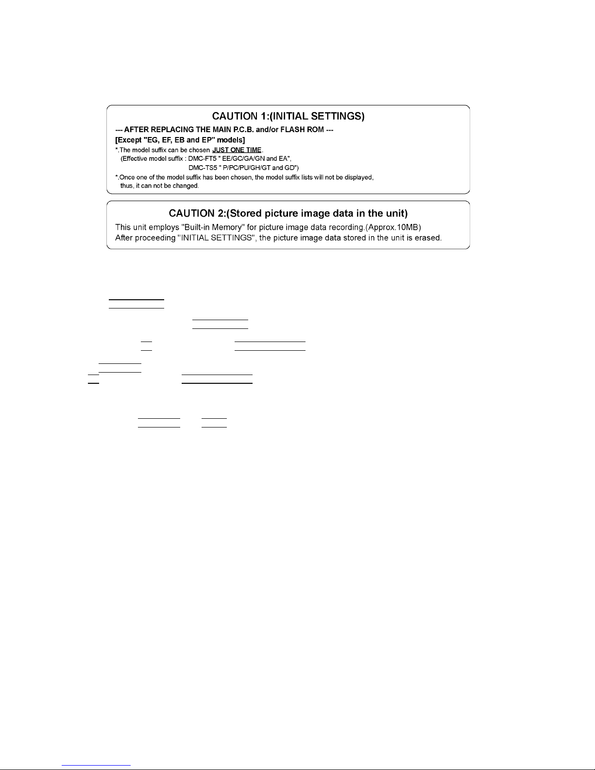
3.5.2. INITIAL SETTINGS:
After replacing the Main P.C.B., be sure to perform the initial settings after achieving the adjustment by ordering the following
procedure in accordance with model suffix of the unit.
1. IMPORTANT NOTICE:
Before proceeding Initial settings, be sure to read the following CAUTIONS.
2. PROCEDURES:
• Precautions: Read the above "CAUTION 1" and "CAUTION 2", carefully
• Preparation:
1. Attach the Battery to the unit.
2. Set to P(Program AE)
mode by operating the mode button.
Note:
If the picture mode is other than P(Program AE)
mode, it does not display the initial settings menu.
• Step 1. The temporary cancellation of "INITIAL SETTINGS":
While keep pressing "UP
of Cursor button" and MOTION PICTURE button simultaneously, turn the Power on.
• Step 2. The cancellation of "INITIAL SETTINGS":
Press the PLAYBACK
button.
Press "UP
of Cursor button" and MOTION PICTURE button simultaneously, then turn the Power off.
• Step 3. Turn the Power on:
Turn the Power on.
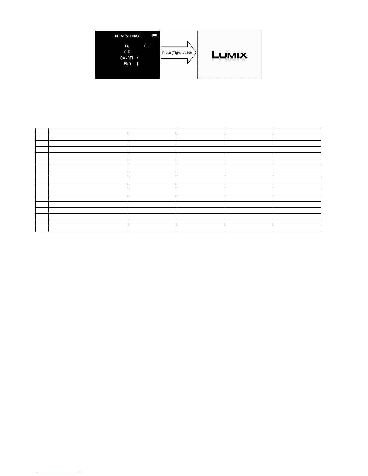
• Step 4. Display the "INITIAL SETTINGS" me nu:
While keep pressing MENU/SET
and "RIGHT of Cursor button" simultaneously, turn the Power off.
The "INITIAL SETTINGS" menu is displayed.
There are two kinds of "INITIAL SETTINGS" menu form as follows:
[CASE 1. After replacing Main P.C.B.]
[Except "EG, EF, EB and EP" models : (VEP56172A is used as a Main P.C.B.)]
When Main P.C.B. has just been replaced, the following model suffix list is displayed as follows. (Four pages in total)

15
[Only for "EG, EF, EB and EP" models : (VEP56172B is used as a Main P.C.B.)]
When Main P.C.B. has just been replaced, only 8 model suffix list is displayed as follows. (Two pages in total)
[CASE 2. Other than "After replacing Main P.C.B."]
• Step 5. Choose the model suffix in "INITIAL SETTINGS": (Refer to "CAUTION 1")
[Caution: After replacing Main P.C.B.]
(Especially, other than "EG, EF, EB and EP" models)
The model suffix can be chosen, JUST ONE TIME.
Once one of the model suffix have been chosen, the model suffix lists will not be displayed, thus, it can be changed.
Therefore, select the area carefully.
Select the area with pressing "UP
/ DOWN of Cursor buttons".
• Step 6. Set the model suffix at "INITIAL SETTINGS":
Press the "RIGHT
of Cursor buttons".
The only set area is displayed. Press the "RIGHT
of Cursor buttons" after confirmation.
(The unit is powered off automatically.)
16
• Step 7. CONFIRMATION:
Confirm the display of "PLEASE SET THE CLOCK" in concerned language when the unit is turned on again .
When the unit is connected to PC with USB cable, it is detected as removable media.
1) As for your reference, major default setting condition is as shown in the following table.
• Default setting (After "INITIAL SETTINGS")
MODEL VIDEO OUTPUT LANGUAGE DATE REMARKS
a) DMC-FT5(Japan domestic model) NTSC Japanese Year/Month/Date
b) DMC-FT5EB PAL English Date/Month/Year
c) DMC-FT5EE PAL Russian Date/Month/Year
d) DMC-FT5EF PAL French Date/Month/Year
e) DMC-FT5EG PAL English Date/Month/Year
f) DMC-FT5EP PAL English Date/Month/Year
g) DMC-FT5GC PAL English Date/Month/Year
h) DMC-FT5GA PAL English Date/Month/Year
i) DMC-FT5GN PAL English Date/Month/Year
j) DMC_FT5EA PAL Russian Date/Month/Year
k) DMC-TS5GH PAL English Date/Month/Year
l) DMC-TS4GT NTSC Chinese (Traditional) Year/Month/Date
m) DMC-TS5GD NTSC Korean Year/Month/Date
n) DMC-TS5P NTSC English Date/Month/Year
o) DMC-TS5PC NTSC English Date/Month/Year
p) DMC-TS5PU NTSC Spanish Date/Month/Year
17
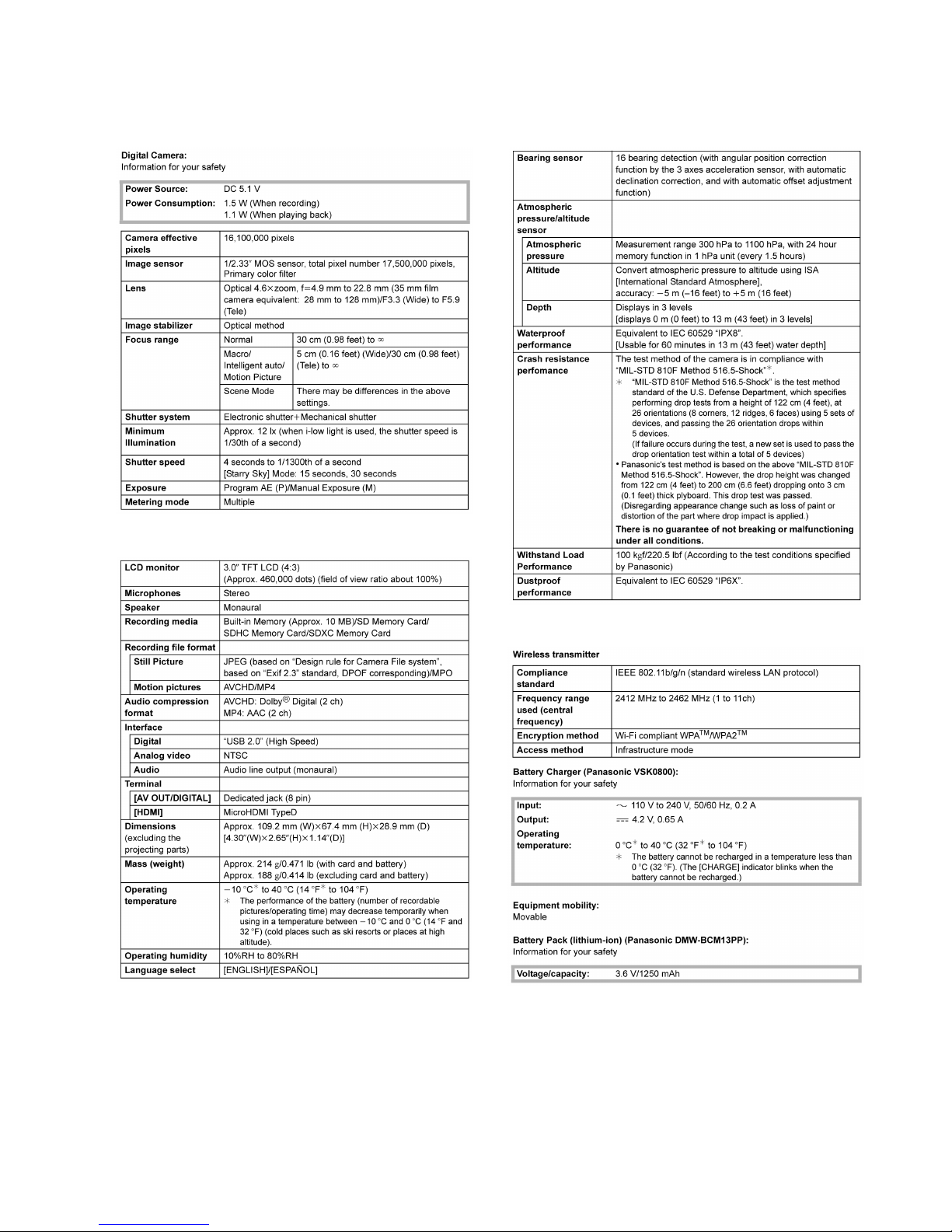
4 Specifications
The following specification is for DMC-TS5P.
Some specifications may differ depending on model suffix.
18
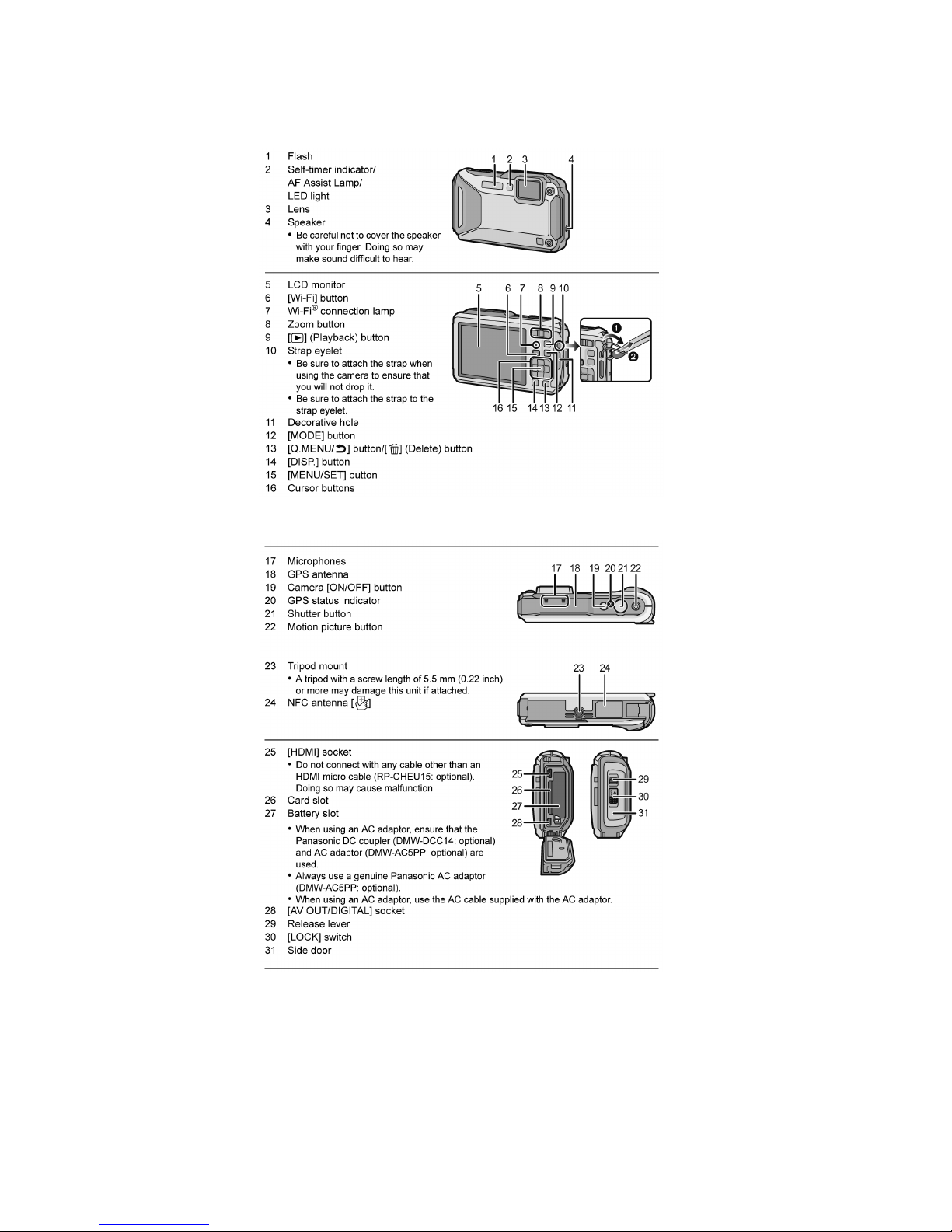
5 Location of Controls and Components
The following specification is for DMC-TS5P.
Some specifications may differ depending on model suffix.

19
6 Service Mode
6.1. Error Code Memory Function
1. General description
This unit is equipped with history of error code memory function, and can be memorized 16 error codes in sequence from the
latest. When the error is occurred more than 16, the oldest error is overwritten in sequence.
The error code is not memorized when the power supply is shut down forcibly (i.e.,when the unit is powered on by the battery,
the battery is pulled out) The error code is memorized to FLASH ROM when the unit has just before powered off.
2. How to display
The error code can be displayed by ordering the following procedure:
• Preparation:
1. Attach the Battery to the unit.
Note:
*Since this unit has built-in memory, it can be performed without inserting Memory Card.
• Step 1. The temporary cancellation of "INITIAL SETTINGS":
While keep pressing "UP
of Cursor button" and MOTION PICTURE button simultaneously, turn the Power on.
• Step 2. Execute the error code display mode:
Press the "LEFT
of Cursor button", MENU/SET button and MOTION PICTURE button simultaneously.
The display is changed as shown below when the above buttons are pressed simultaneously.
Normal display
→ Error code display → CAMERA INFO → Normal display → .....
 Loading...