

Panasonic DMC-FT4EB, DMC-FT4EE, DMC-FT4EF, DMC-FT4EG, DMC-FT4EP Service Manual
...
© Panasonic Corporation 2012.
Unauthorized copying and distribution is a violation
of law.
ORDER NO.DSC1203010CE
B26
Digital Camera
Model No. DMC-FT4EB
DMC-FT4EE
DMC-FT4EF
DMC-FT4EG
DMC-FT4EP
DMC-FT4GC
DMC-FT4GN
DMC-TS4P
DMC-TS4PC
DMC-TS4PU
DMC-TS4GH
DMC-TS4GD
Colours
(A)....................Blue Type (Except DMC-FT4EE/EF)
(D)....................Orange Type
(S)....................Silver Type (Except DMC-FT4EF, DMC-
TS4GD/PC)
(K)....................Black Type (Except DMC-FT4EE, DMC-
TS4GD/GH)

2
TABLE OF CONTENTS
PAG E PAG E
1 Safety Precautions -----------------------------------------------3
1.1. General Guidelines ----------------------------------------3
1.2. Leakage Current Cold Check ---------------------------3
1.3. Leakage Current Hot Check (See Figure 1)---------3
1.4. How to Discharge the Capacitor on Flash
CON P.C.B. --------------------------------------------------4
2Warning--------------------------------------------------------------5
2.1. Prevention of Electrostatic Discharge (ESD)
to Electrostatic Sensitive (ES) Devices---------------5
2.2. How to Recycle the Lithium Ion Battery (U.S.
Only)-----------------------------------------------------------5
2.3. Caution for AC Cord (For EB/GC/GH) ----------------6
2.4. How to Replace the Lithium Battery -------------------7
3 Service Navigation------------------------------------------------9
3.1. Introduction --------------------------------------------------9
3.2. Air-leak test (inspection)----------------------------------9
3.3. Replacing the waterproof packing (waterproof
seal) -----------------------------------------------------------9
3.4. Lens Unit -----------------------------------------------------9
3.5. About IC9301 (COMPASS) [On the TOP FPC
UNIT] -------------------------------------------------------- 10
3.6. General Description About Lead Free Solder
(PbF) -------------------------------------------------------- 10
3.7. How to Define the Model Suffix (NTSC or PAL
model)------------------------------------------------------- 11
4 Specifications ---------------------------------------------------- 15
5 Location of Controls and Components------------------ 20
6 Service Mode ----------------------------------------------------- 22
6.1. Error Code Memory Function -------------------------22
6.2. ICS (Indication of additional Camera Settings
when picture was taken) function -------------------- 25
7 Troubleshooting Guide---------------------------------------- 27
7.1. Service and Check Procedures ---------------------- 27
7.2. Air-leak Test ----------------------------------------------- 30
7.3. Checking Method of GPS failure --------------------- 31
7.4. Checking Method of compass, altimeter, &
barometer -------------------------------------------------- 32
8 Service Fixture & Tools --------------------------------------- 36
8.1. Service Fixture and Tools ------------------------------ 36
8.2. When Replacing the Main P.C.B. -------------------- 37
8.3. Service Position ------------------------------------------ 37
9 Disassembly and Assembly Instructions--------------- 38
9.1. Disassembly Flow Chart-------------------------------- 38
9.2. P.C.B. Location ------------------------------------------- 38
9.3. Disassembly Procedures------------------------------- 39
10 Measurements and Adjustments -------------------------- 48
10.1. Introduction ------------------------------------------------48
10.2. Before Disassembling the unit ------------------------ 48
10.3. Details of Electrical Adjustment----------------------- 50
10.4. After Adjustment------------------------------------------53
11 Maintenance ------------------------------------------------------ 54
11.1. Cleaning Lens and LCD Panel ----------------------- 54
12 Block Diagram --------------------------------------------------- 55
12.1. Overall Block Diagram ---------------------------------- 55
12.2. System Control Block Diagram ----------------------- 56
12.3. Video/Audio Signal Process Block Diagram------- 57
12.4. Sensor Block Diagram ---------------------------------- 58
12.5. Lens Drive Block Diagram -----------------------------59
12.6. Power Block Diagram----------------------------------- 60
13 Wiring Connection Diagram -------------------------------- 61
13.1. Interconnection Schematic Diagram ---------------- 61
3
1 Safety Precautions
1.1. General Guidelines
1. IMPORTANT SAFETY NOTICE
There are special components used in this equipment
which are important for safety. These parts are marked by
in the Schematic Diagrams, Circuit Board Layout,
Exploded Views and Replacement Parts List. It is
essential that these critical parts should be replaced with
manufacturer's specified parts to prevent X-RADIATION,
shock fire, or other hazards. Do not modify the original
design without permission of manufacturer.
2. An Isolation Transformer should always be used during
the servicing of AC Adaptor whose chassis is not isolated
from the AC power line. Use a transformer of adequate
power rating as this protects the technician from
accidents resulting in personal injury from electrical
shocks. It will also protect AC Adaptor from being
damaged by accidental shorting that may occur during
servicing.
3. When servicing, observe the original lead dress. It a short
circuit is found, replace all parts which have been
overheated or damaged by the short circuit.
4. After servicing, see to it that all the protective devices
such as insulation barriers, insulation papers shields are
properly installed.
5. After servicing, make the following leakage current
checks to prevent the customer from being exposed to
shock hazards.
1.2. Leakage Current Cold Check
1. Unplug the AC cord and connect a jumper between the
two prongs on the plug.
2. Measure the resistance value, with an ohmmeter,
between the jumpered AC plug and each exposed
metallic cabinet part on the equipment such as
screwheads, connectors, control shafts, etc. When the
exposed metallic part has a return path to the chassis, the
reading should be between 1MΩ and 5.2MΩ. When the
exposed metal does not have a return path to the chassis,
the reading must be infinity.
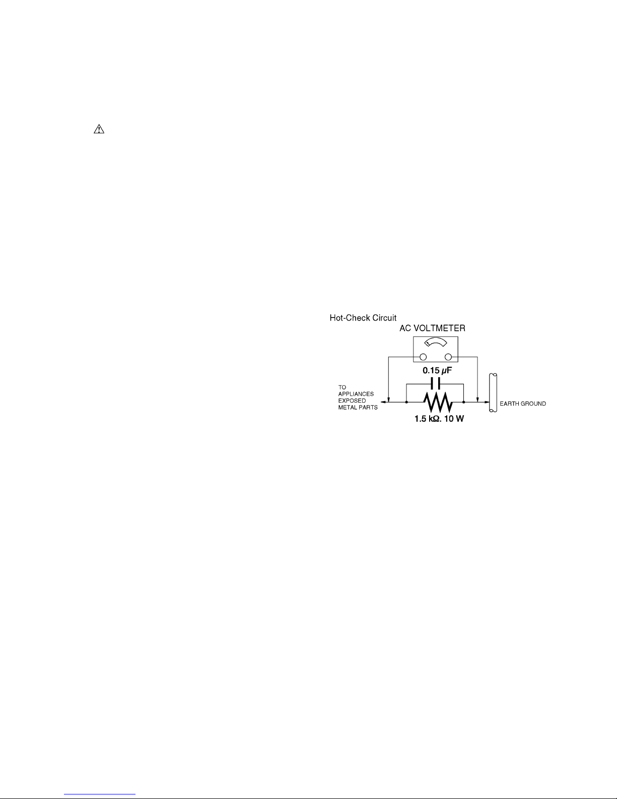
1.3. Leakage Current Hot Check
(See Figure 1)
1. Plug the AC cord directly into the AC outlet. Do not use
an isolation transformer for this check.
2. Connect a 1.5kΩ, 10 W resistor, in parallel with a 0.15μF
capacitor, between each exposed metallic part on the set
and a good earth ground, as shown in Figure 1.
3. Use an AC voltmeter, with 1 kΩ/V or more sensitivity, to
measure the potential across the resistor.
4. Check each exposed metallic part, and measure the
voltage at each point.
5. Reverse the AC plug in the AC outlet and repeat each of
the above measurements.
6. The potential at any point should not exceed 0.75 V RMS.
A leakage current tester (Simpson Model 229 or
equivalent) may be used to make the hot checks, leakage
current must not exceed 1/2 mA. In case a measurement
is outside of the limits specified, there is a possibility of a
shock hazard, and the equipment should be repaired and
rechecked before it is returned to the customer.
Figure 1
4
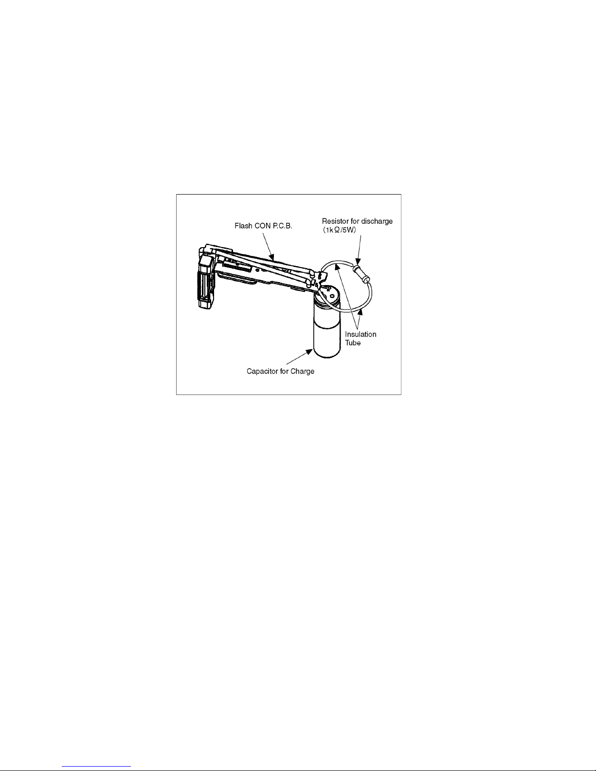
1.4. How to Discharge the Capacitor on Flash CON P.C.B.
• This unit equipped with two pieces of capacitors as flash charging capacitors.
"Either one of the capacitor discharging operation" makes discharging for others as well.
CAUTION:
1. Be sure to discharge the capacitor on Flash CON P.C.B.
2. Be careful of the high voltage circuit on Flash CON P.C.B. when servicing.
[Discharging Procedure]
1. Refer to the disassemble procedure and remove the necessary parts/unit.
2. Put the insulation tube onto the lead part of Resistor (ERG5SJ102:1kΩ /5W).
(An equivalent type of resistor may be used.)
3. Put the resistor between both terminals of capacitor on Flash CON P.C.B. for approx. 5 seconds.
4. After discharging confirm that the capacitor voltage is lower than 10V using a voltmeter.
Fig. F1
5
2Warning
2.1. Prevention of Electrostatic Discharge (ESD) to Electrostatic Sensitive
(ES) Devices
Some semiconductor (solid state) devices can be damaged easily by static electricity. Such components commonly are called
Electrostatically Sensitive (ES) Devices.
The following techniques should be used to help reduce the incidence of component damage caused by electrostatic discharge
(ESD).
1. Immediately before handling any semiconductor component or semiconductor-equipped assembly, drain off any ESD on your
body by touching a known earth ground. Alternatively, obtain and wear a commercially available discharging ESD wrist strap,
which should be removed for potential shock reasons prior to applying power to the unit under test.
2. After removing an electrical assembly equipped with ES devices, place the assembly on a conductive surface such as
aluminum foil, to prevent electrostatic charge buildup or exposure of the assembly.
3. Use only a grounded-tip soldering iron to solder or unsolder ES devices.
4. Use only an antistatic solder removal device. Some solder removal devices not classified as can
generate electrical charge sufficient to damage ES devices.
5. Do not use freon-propelled chemicals. These can generate electrical charges sufficient to damage ES devices.
6. Do not remove a replacement ES device from its protective package until immediately before you are ready to install it. (Most
replacement ES devices are packaged with leads electrically shorted together by conductive foam, aluminum foil or
comparable conductive material).
7. Immediately before removing the protective material from the leads of a replacement ES device, touch the protective material
to the chassis or circuit assembly into which the device will be installed.
CAUTION:
Be sure no power is applied to the chassis or circuit, and observe all other safety precautions.
8. Minimize bodily motions when handling unpackaged replacement ES devices. (Otherwise harmless motion such as the
brushing together of your clothes fabric or the lifting of your foot from a carpeted floor can generate static electricity (ESD)
sufficient to damage an ES device).
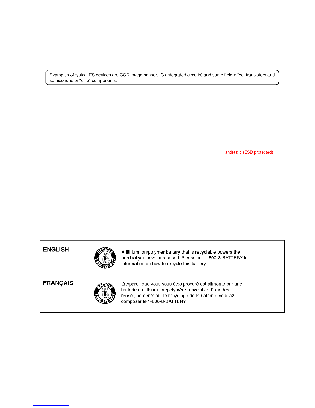
2.2. How to Recycle the Lithium Ion Battery (U.S. Only)
6
2.3. Caution for AC Cord (For EB/
GC/GH)
2.3.1. Information for Your Safety
IMPORTANT
Your attention is drawn to the fact that recording of prerecorded tapes or discs or other published or broadcast
material may infringe copyright laws.
WARNING
To reduce the risk of fire or shock hazard, do not expose
this equipment to rain or moisture.
CAUTION
To reduce the risk of fire or shock hazard and annoying
interference, use the recommended accessories only.
FOR YOUR SAFETY
DO NOT REMOVE THE OUTER COVER
To prevent electric shock, do not remove the cover. No user
serviceable parts inside. Refer servicing to qualified service
personnel.
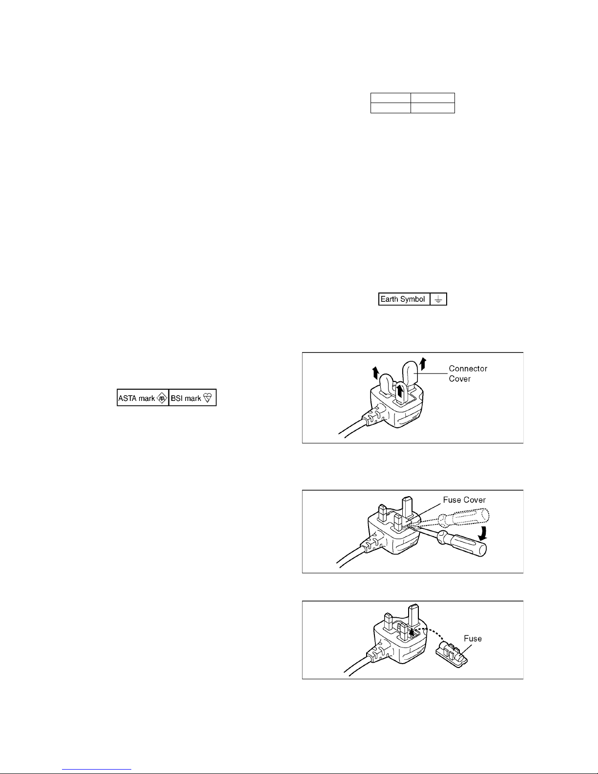
2.3.2. Caution for AC Mains Lead
For your safety, please read the following text carefully.
This appliance is supplied with a moulded three-pin mains plug
for your safety and convenience.
A 5-ampere fuse is fitted in this plug.
Should the fuse need to be replaced please ensure that the
replacement fuse has a rating of 5 amperes and it is approved
by ASTA or BSI to BS1362
Check for the ASRA mark or the BSI mark on the body of the
fuse.
If the plug contains a removable fuse cover you must ensure
that it is refitted when the fuse is replaced.
If you lose the fuse cover, the plug must not be used until a
replacement cover is obtained.
A replacement fuse cover can be purchased from your local
Panasonic Dealer.
If the fitted moulded plug is unsuitable for the socket outlet in
your home then the fuse should be removed and the plug cut
off and disposed of safety.
There is a danger of severe electrical shock if the cut off plug is
inserted into any 13-ampere socket.
If a new plug is to be fitted please observe the wiring code as
shown below.
If in any doubt, please consult a qualified electrician.
2.3.2.1. Important
The wires in this mains lead are coloured in accordance with
the following code:
As the colours of the wires in the mains lead of this appliance
may not correspond with the coloured markings identifying the
terminals in your plug, proceed as follows:
The wire which is coloured BLUE must be connected to the
terminal in the plug which is marked with the letter N or
coloured BLACK.
The wire which is coloured BROWN must be connected to the
terminal in the plug which is marked with the letter L or coloured
RED.
Under no circumstances should either of these wires be
connected to the earth terminal of the three pin plug, marked
with the letter E or the Earth Symbol.
2.3.2.2. Before Use
remove the Connector Cover as follows.
2.3.2.3. How to Replace the Fuse
1. Remove the Fuse Cover with a screwdriver.
2. Replace the fuse and attach the Fuse cover.
Blue Neutral
Brown Live
7
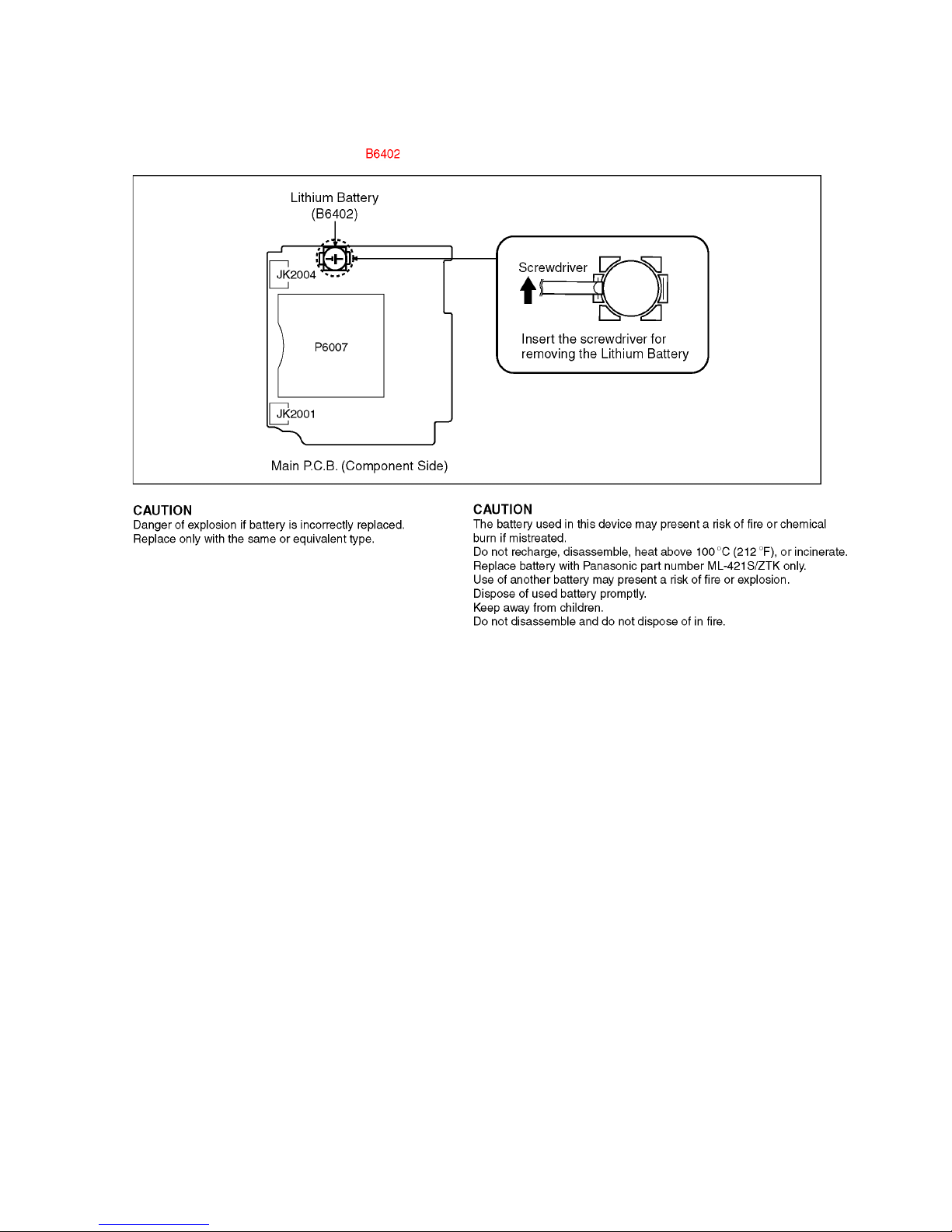
2.4. How to Replace the Lithium Battery
2.4.1. Replacement Procedure
1. Remove the Main P.C.B. (Refer to Disassembly Procedures.)
2. Remove the Lithium battery (Ref. No. at foil side of Main P.C.B.) and then replace it into new one.
Note:
The lithium battery is a critical component.
(Type No.: ML-421S/ZTK Manufactured by Energy Company, Panasonic Corporation)
It must never be subjected to excessive heat or discharge.
It must therefore only be fitted in equipment designed specifically for its use.
Replacement batteries must be of the same type and manufacture.
They must be fitted in the same manner and location as the original battery, with the correct polarity contacts observed.
Do not attempt to re-charge the old battery or re-use it for any other purpose.
It should be disposed of in waste products destined for burial rather than incineration.
8
Note:
Above caution is applicable for a battery pack which is for DMC-FT4 and DMC-TS4 series, as well.
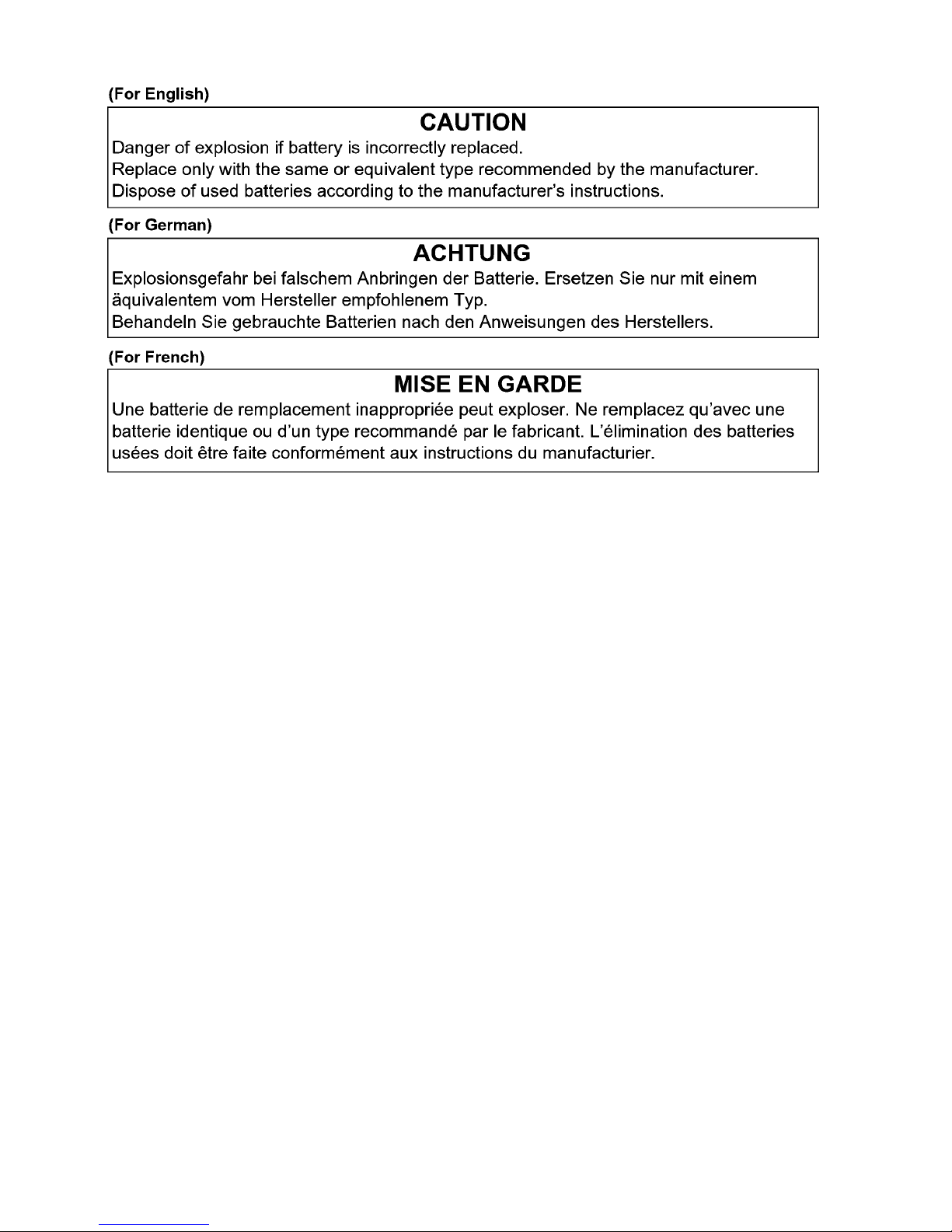
Danger of explosion if battery is incorrectly replaced.
Replace only with the same or equivalent type recommended by the manufacturer.
Dispose of used batteries according to the manufacturer's instructions.
9
3 Service Navigation
3.1. Introduction
This service manual contains technical information, which will allow service personnel's to understand and service this model.
Please place orders using the parts list and not the drawing reference numbers.
If the circuit is changed or modified, the information will be followed by service manual to be controlled with original service manual.
3.2. Air-leak test (inspection)
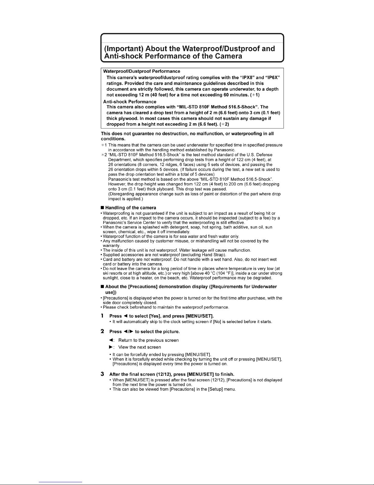
This does not guarantee no destruction, no malfunction, or waterproofing in all conditions.
*1 This means that the camera can be used underwater for specified time in specified pressure in accordance with the handling
method established by Panasonic.
*2 "MIL-STD 810F Method 516.5-Shock" is the test method standard of the U.S. Defense Department, which specifies
performing drop tests from a height of 122 cm (4.0 feet), at 26 orientations (8 corners, 12 ridges, 6 faces) using 5 sets of
devices, and passing the 26 orientation drops within 5 devices. (If failure occurs during the test, a new set is used to pass the
drop orientation test within a total of 5 devices)
Panasonic’s test method is based on the above "MIL-STD 810F Method 516.5-Shock". However, the drop height was changed
from 122 cm (4.0 feet) to 200 cm (6.6 feet) dropping onto 3 cm (0.10 feet) thick plyboard. This drop test was passed.
(Disregarding appearance change such as loss of paint or distortion of the part where drop impact is applied.)
• Due to the above characteristics of the products, perform the air-leak test (inspection) using Air -leak tester (Part No.:RFKZ0528)
before/after servicing including assembly and/or assembly process.
Note:
The purpose of the air-leak test before servicing is that whether the malfunction occurred due to air-leak or not.
• When servicing, refer to the "7.Troubleshooting Guide" section for details.
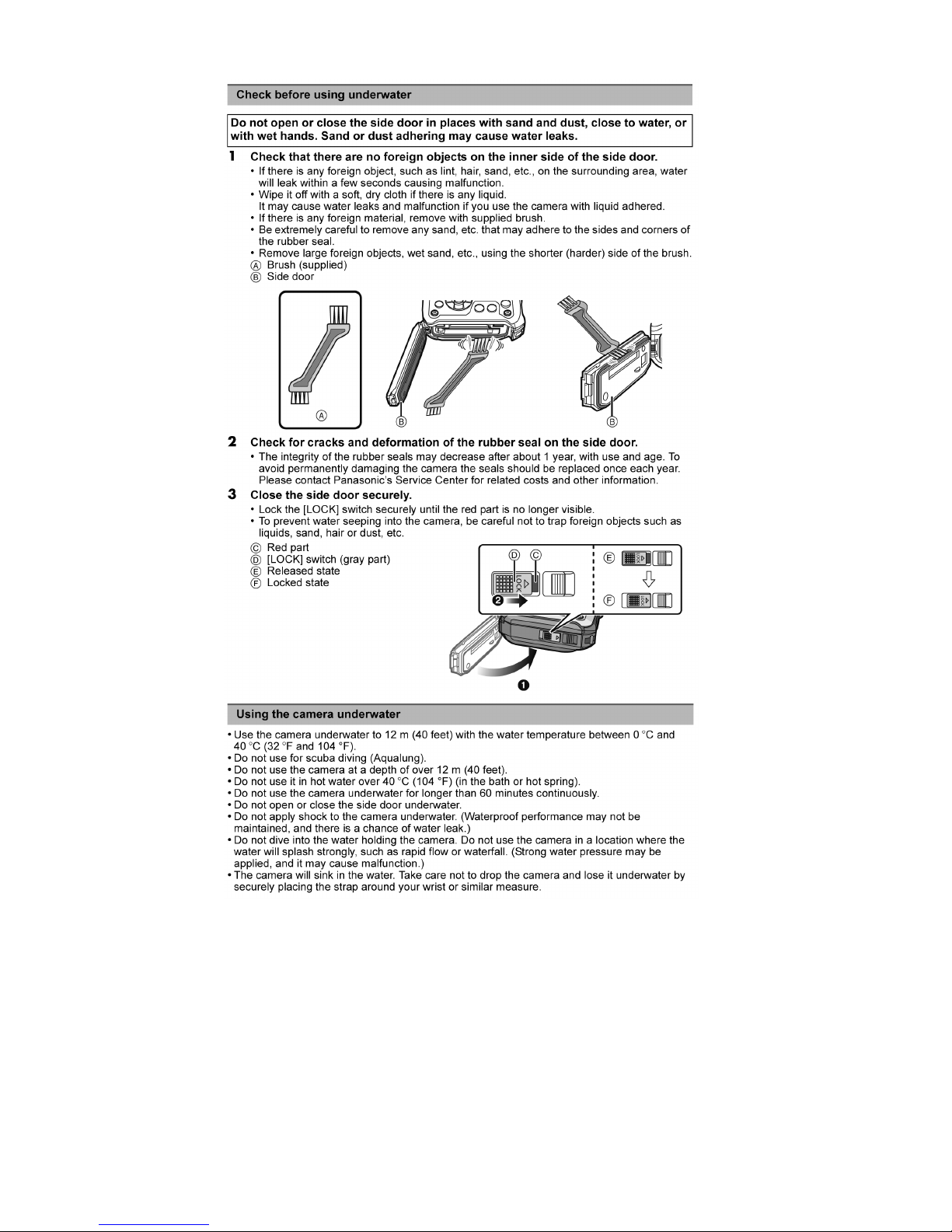
3.3. Replacing the waterproof packing (waterproof seal)
• The integrity of the waterproof packing may decrease about 1 year, with use and age.
(We recommend end users to replace the waterproof packing (waterproof seal) at least once each year described in the
operating instructions.)
• As for replacement procedure, refer to the 7.1.2. Periodical maintenance (Packing replacement) flow for details.
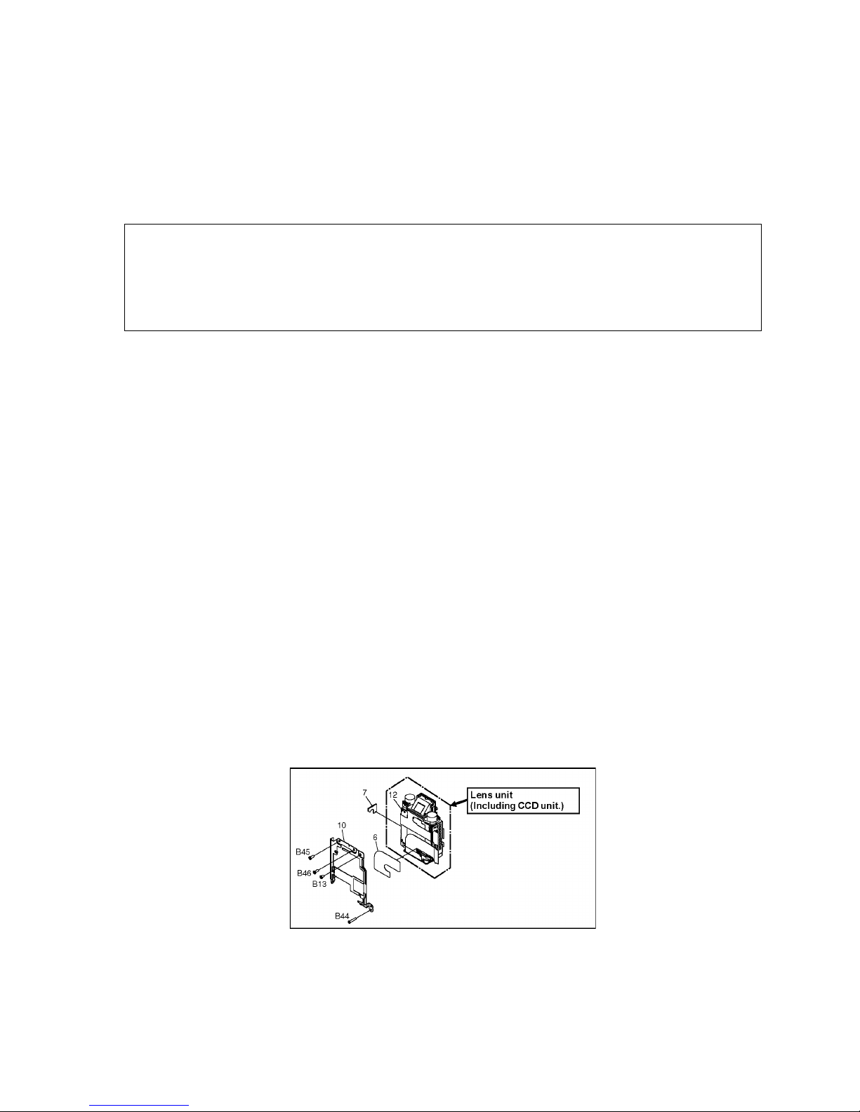
3.4. Lens Unit
• Since the lens unit for this model is assembled with high accuracy manufacturing technologies, it is not allowed to disassemble/
assemble the lens unit, in terms of performance retention.
When servicing, it has to be handled the "Lens with CCD unit" as the smallest part size.
Confirm the replacement part list and exploded views for details.
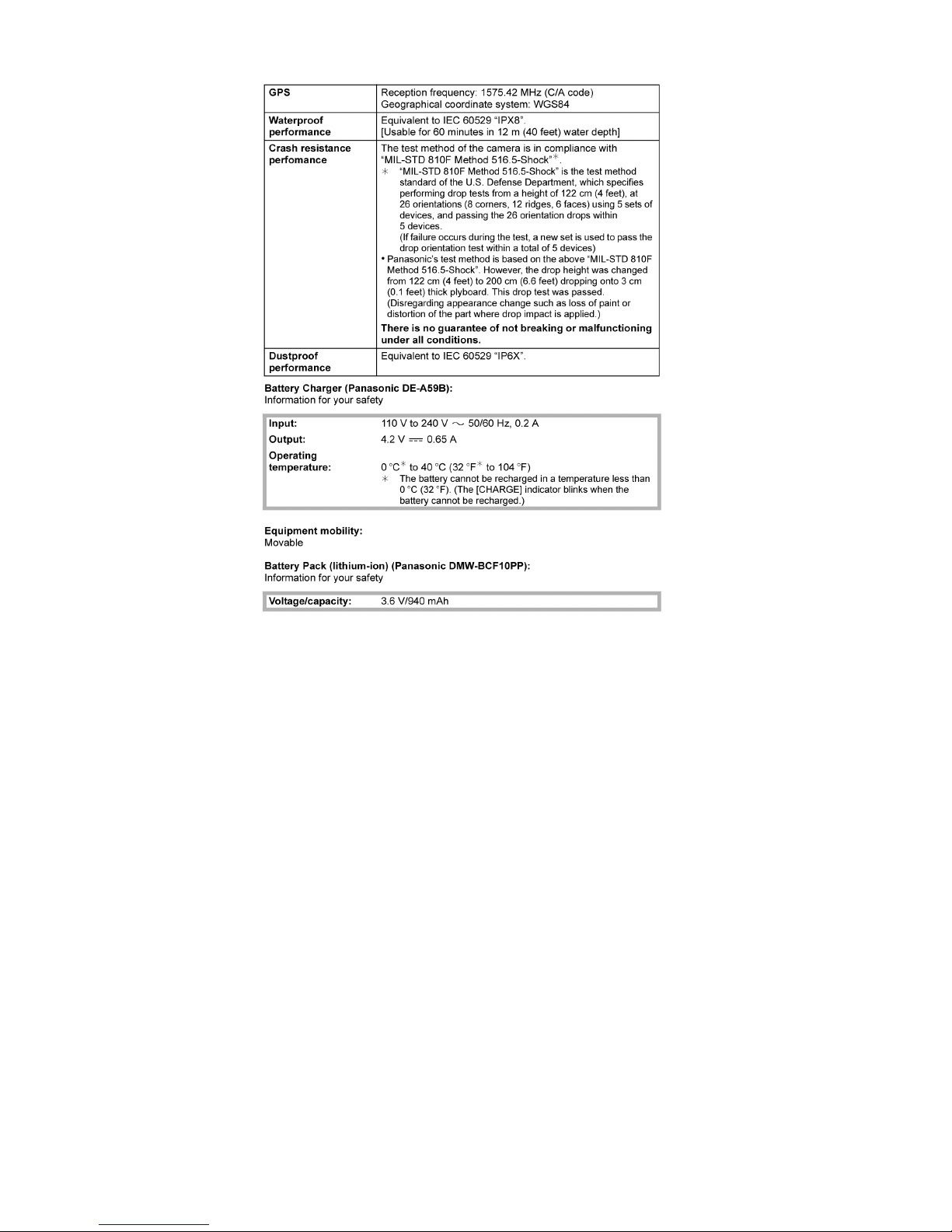
Waterproof/Dustproof Performance
This camera's waterproof/dustproof rating complies with the "IPX8" and "IP6X" ratings. Provided the care and maintenance guidelines
described in this document are strictly followed, this camera can operate underwater, to a depth not exceeding 12 m (40 feet) for a time
not exceeding 60 minutes. (*1)
Anti-shock Performance
This camera also complies with "MIL-STD 810F Method 516.5-Shock". The camera has cleared a drop test from a height of 2 m (6.6
feet) onto 3 cm (0.10 feet) thick plywood. In most cases this camera should not sustain any damage if dropped from a height not
exceeding 2 m (6.6 feet). (*2)
10
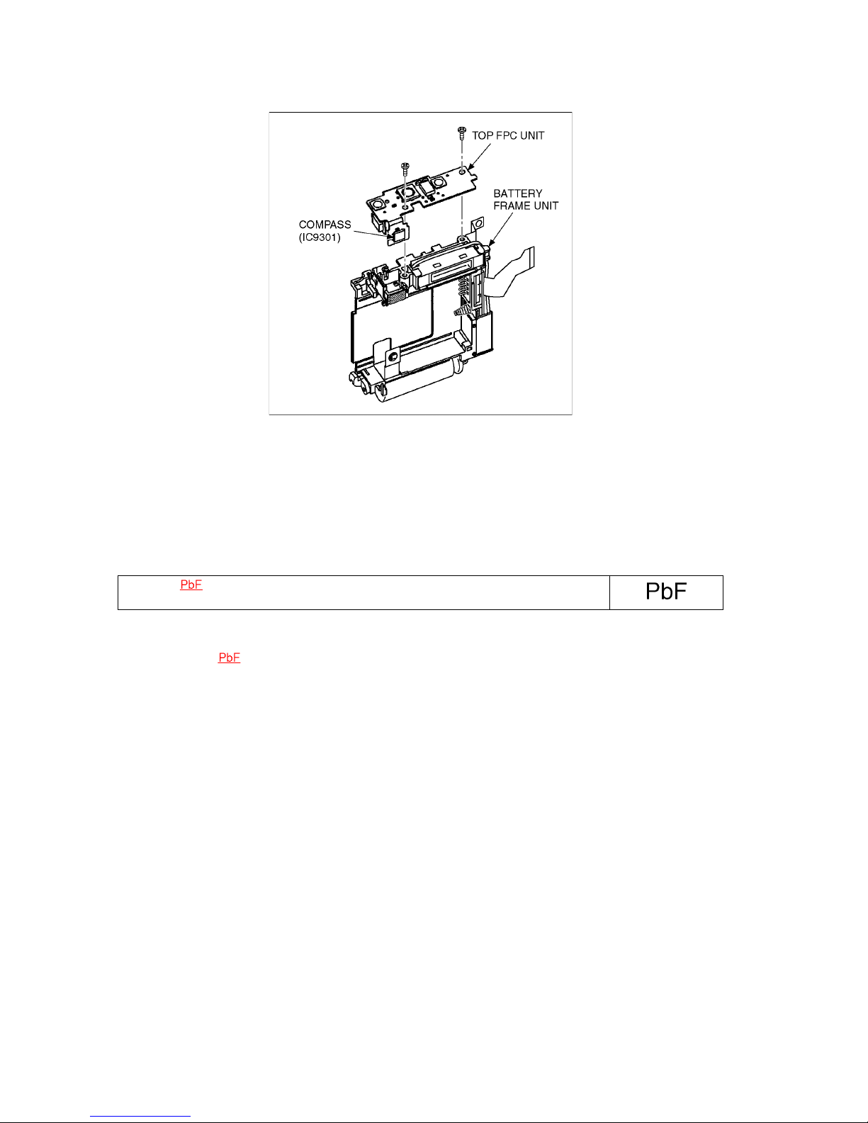
3.5. About IC9301 (COMPASS) [On the TOP FPC UNIT]
When IC9301 is defects and necessary to be replaced, replace with whole TOP FPC UNIT as a unit.
3.6. General Description About Lead Free Solder (PbF)
The lead free solder has been used in the mounting process of all electrical components on the printed circuit boards used for this
equipment in considering the globally environmental conservation.
The normal solder is the alloy of tin (Sn) and lead (Pb). On the other hand, the lead free solder is the alloy mainly consists of tin
(Sn), silver (Ag) and Copper (Cu), and the melting point of the lead free solder is higher approx.30 °C (86 °F) more than that of the
normal solder.
Definition of P.C.B. Lead Free Solder being used
Service caution for repair work using Lead Free Solder (PbF)
• The lead free solder has to be used when repairing the equipment for which the lead free solder is used.
• (Definition: The letter of is printed on the P.C.B. using the lead free solder.)
• To put lead free solder, it should be well molten and mixed with the original lead free solder.
• Remove the remaining lead free solder on the P.C.B. cleanly for soldering of the new IC.
• Since the melting point of the lead free solder is higher than that of the normal lead solder, it takes the longer time to melt the
lead free solder.
• Use the soldering iron (more than 70W) equipped with the temperature control after setting the temperature at 350±30 degrees
C (662±86 °F).
Recommended Lead Free Solder (Service Parts Route.)
• The following 3 types of lead free solder are available through the service parts route.
RFKZ03D01KS-----------(0.3mm 100g Reel)
RFKZ06D01KS-----------(0.6mm 100g Reel)
RFKZ10D01KS-----------(1.0mm 100g Reel)
Note
* Ingredient: tin (Sn) 96.5%, silver (Ag) 3.0%, Copper (Cu) 0.5%, Cobalt (Co) / Germanium (Ge) 0.1 to 0.3%
The letter of is printed either foil side or components side on the P.C.B. using the lead free solder.
(See right figure)
11
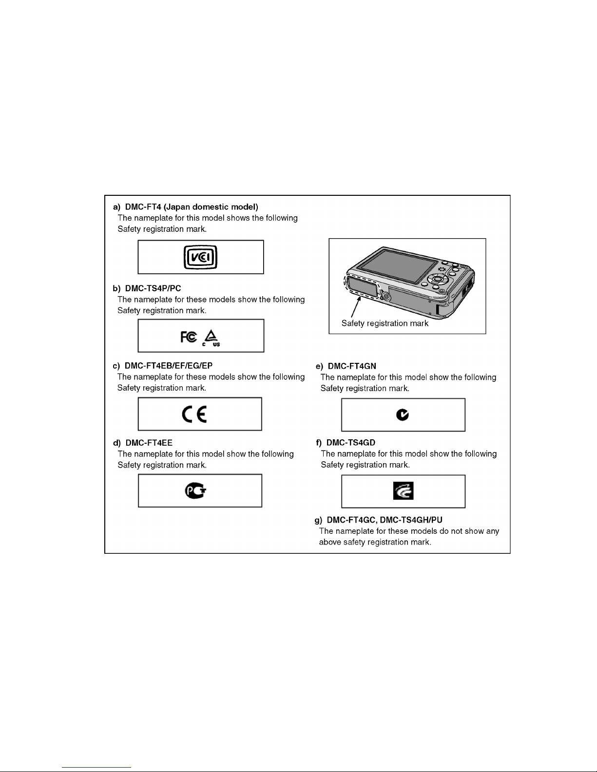
3.7. How to Define the Model Suffix (NTSC or PAL model)
There are seven kinds of DMC-FT4/TS4, regardless of the colours.
• a) DMC-FT4 (Japan domestic model.)
• b) DMC-TS4P/PC
• c) DMC-FT4EB/EF/EG/EP
• d) DMC-FT4EE
• e) DMC-FT4GN
• f) DMC-TS4GD
• g) DMC-FT4GC, DMC-TS4GH/PU
What is the difference is that the "INITIAL SETTINGS" data which is stored in Flash ROM mounted on Main P.C.B.
3.7.1. Defining methods
To define the model suffix to be serviced, refer to the nameplate which is putted on the bottom side of the Unit.
Note:
After replacing the Main P.C.B., be sure to achieve adjustment.
The Maintenance software (DIAS) is available at "software download" on the "Support Information from NWBG/VDBG-AVC"
web-site in "TSN system".
12
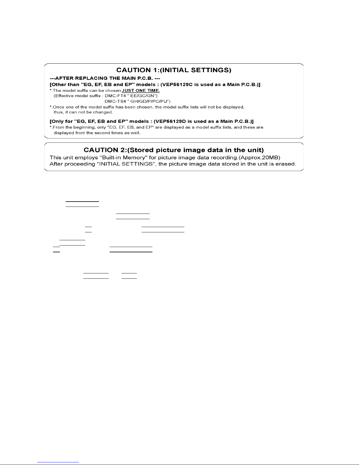
3.7.2. INITIAL SETTINGS:
After replacing the Main P.C.B., be sure to perform the initial settings after achieving the adjustment by ordering the following
procedure in accordance with model suffix of the unit.
1. IMPORTANT NOTICE:
Before proceeding Initial settings, be sure to read the following CAUTIONS.
2. PROCEDURES:
• Precautions: Read the above "CAUTION 1" and "CAUTION 2", carefully
• Preparation:
1. Attach the Battery to the unit.
2. Set to P(Program AE)
mode by operating the mode button.
Note:
If the picture mode is other than P(Program AE)
mode, it does not display the initial settings menu.
• Step 1. The temporary cancellation of "INITIAL SETTINGS":
While keep pressing "UP
of Cursor button" and MOTION PICTURE button simultaneously, turn the Power on.
• Step 2. The cancellation of "INITIAL SETTINGS":
Press the PLAYBACK
button.
Press "UP
of Cursor button" and MOTION PICTURE button simultaneously, then turn the Power off.
• Step 3. Turn the Power on:
Turn the Power on.
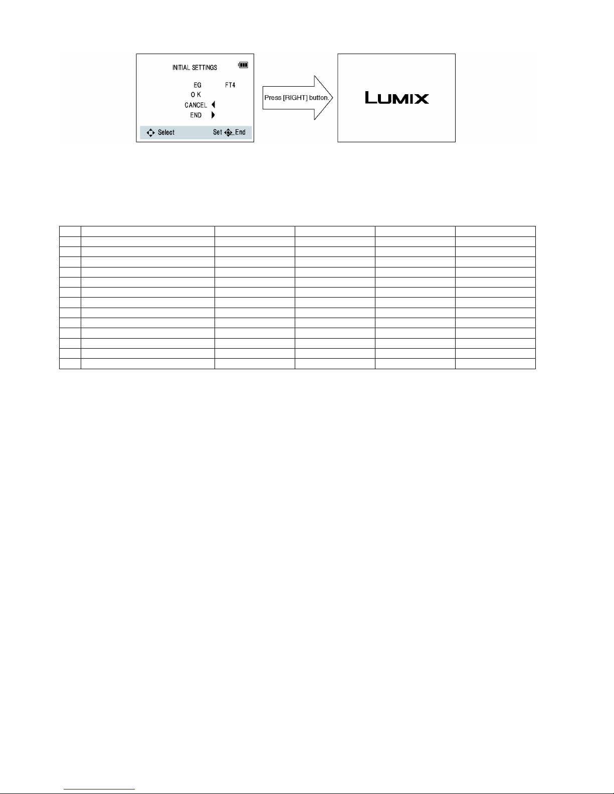
• Step 4. Display the "INITIAL SETTINGS" menu:
While keep pressing MENU/SET
and "RIGHT of Cursor button" simultaneously, turn the Power off.
The "INITIAL SETTINGS" menu is displayed.
There are two kinds of "INITIAL SETTINGS" menu form as follows:
[CASE 1. After replacing Main P.C.B.]
[Except "EG, EF, EB and EP" models : (VEP56129C is used as a Main P.C.B.)]
When Main P.C.B. has just been replaced, the following model suffix list is displayed as follows. (Four pages in total)
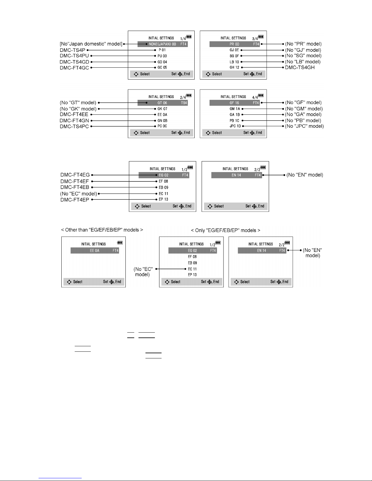
13
[Only for "EG, EF, EB and EP" models : (VEP56129D is used as a Main P.C.B.)]
When Main P.C.B. has just been replaced, the following model suffix list is displayed as follows. (Two pages in total)
[CASE 2. Other than "After replacing Main P.C.B."]
• Step 5. Choose the model suffix in "INITIAL SETTINGS": (Refer to "CAUTION 1")
[Caution: After replacing Main P.C.B.]
(Especially, other than "EG, EF, EB and EP" models : (VEP56129D is used as a Main P.C.B.))
The model suffix can be chosen, JUST ONE TIME.
Once one of the model suffix have been chosen, the model suffix lists will not be displayed, thus, it can be changed.
Therefore, select the area carefully.
Select the area with pressing "UP
/ DOWN of Cursor buttons".
• Step 6. Set the model suffix at "INITIAL SETTINGS":
Press the "RIGHT
of Cursor buttons".
The only set area is displayed. Press the "RIGHT
of Cursor buttons" after confirmation.
(The unit is powered off automatically.)
14
• Step 7. CONFIRMATION:
Confirm the display of "PLEASE SET THE CLOCK" in concerned language when the unit is turned on again.
When the unit is connected to PC with USB cable, it is detected as removable media.
1) As for your reference, major default setting condition is as shown in the following table.
Default setting (After "INITIAL SETTINGS")
MODEL VIDEO OUTPUT LANGUAGE DATE REMARKS
a) DMC-FT4(Japan domestic model) NTSC Japanese Year/Month/Date
b) DMC-FT4EB PAL English Date/Month/Year
c) DMC-FT4EE PAL Russian Date/Month/Year
d) DMC-FT4EF PAL French Date/Month/Year
e) DMC-FT4EG PAL English Date/Month/Year
f) DMC-FT4EP PAL English Date/Month/Year
g) DMC-FT4GC PAL English Date/Month/Year
h) DMC-FT4GN PAL English Date/Month/Year
i) DMC-TS4GH PAL English Date/Month/Year
j) DMC-TS4GD NTSC Korean Year/Month/Date
k) DMC-TS4P NTSC English Date/Month/Year
l) DMC-TS4PC NTSC English Date/Month/Year
m) DMC-TS4PU NTSC Spanish Date/Month/Year
15
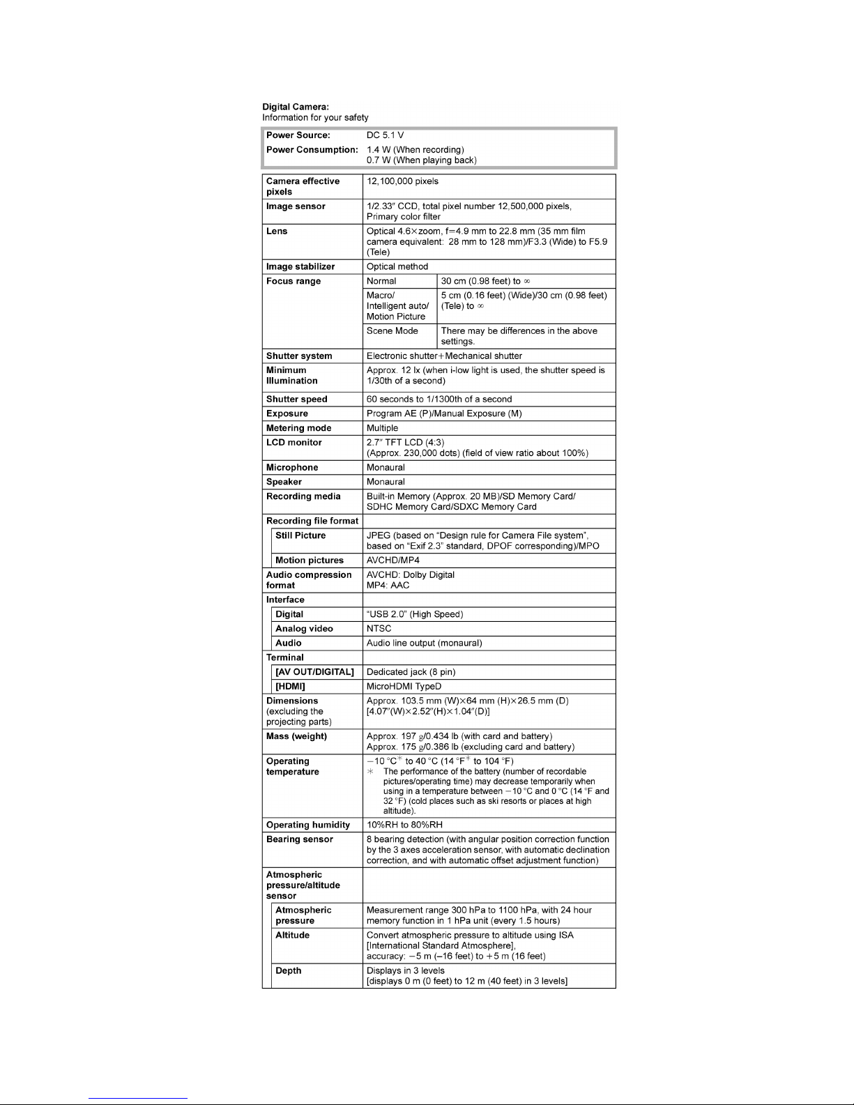
4 Specifications
16
Note:
*Above specification is for DMC-TS4P. Some of the specification may differ depends on model suffix.
[1] Only for "EB/EF/EG/EP" models:
1). [Interface Digital:]
• Data from the PC can not be written to the camera using the USB connection cable.
[2] Others:
1). [Analog video/audio:]
NTSC ----------------------------------------------------------(Only "P/PC/PU/GD" models)
NTSC/PAL Composite (Switched by menu) ----------(Except "P/PC/PU/GD" models)
2). [Motion pictures:]
• Maximum time to record motion pictures continuously with [GFS]/[FSH] in [AVCHD] is 29 minutes 59 seconds.
17
18
19
20
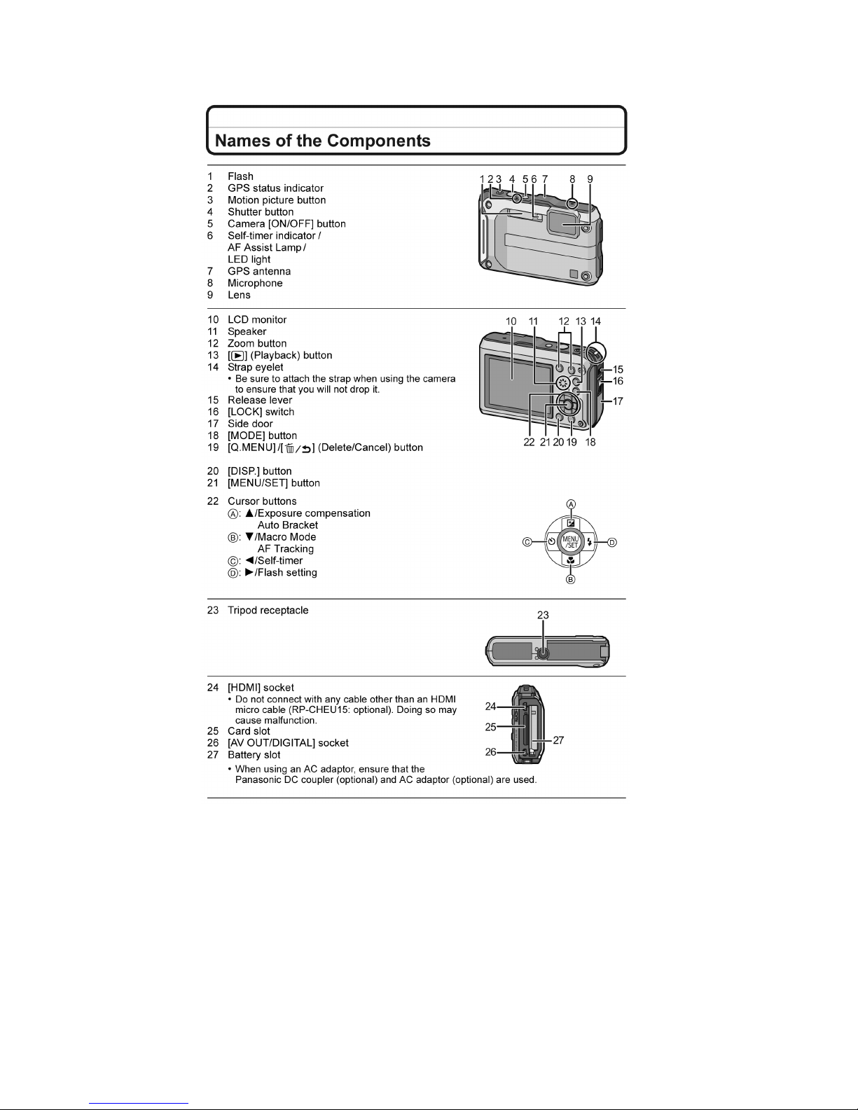
5 Location of Controls and Components
21
22
6 Service Mode
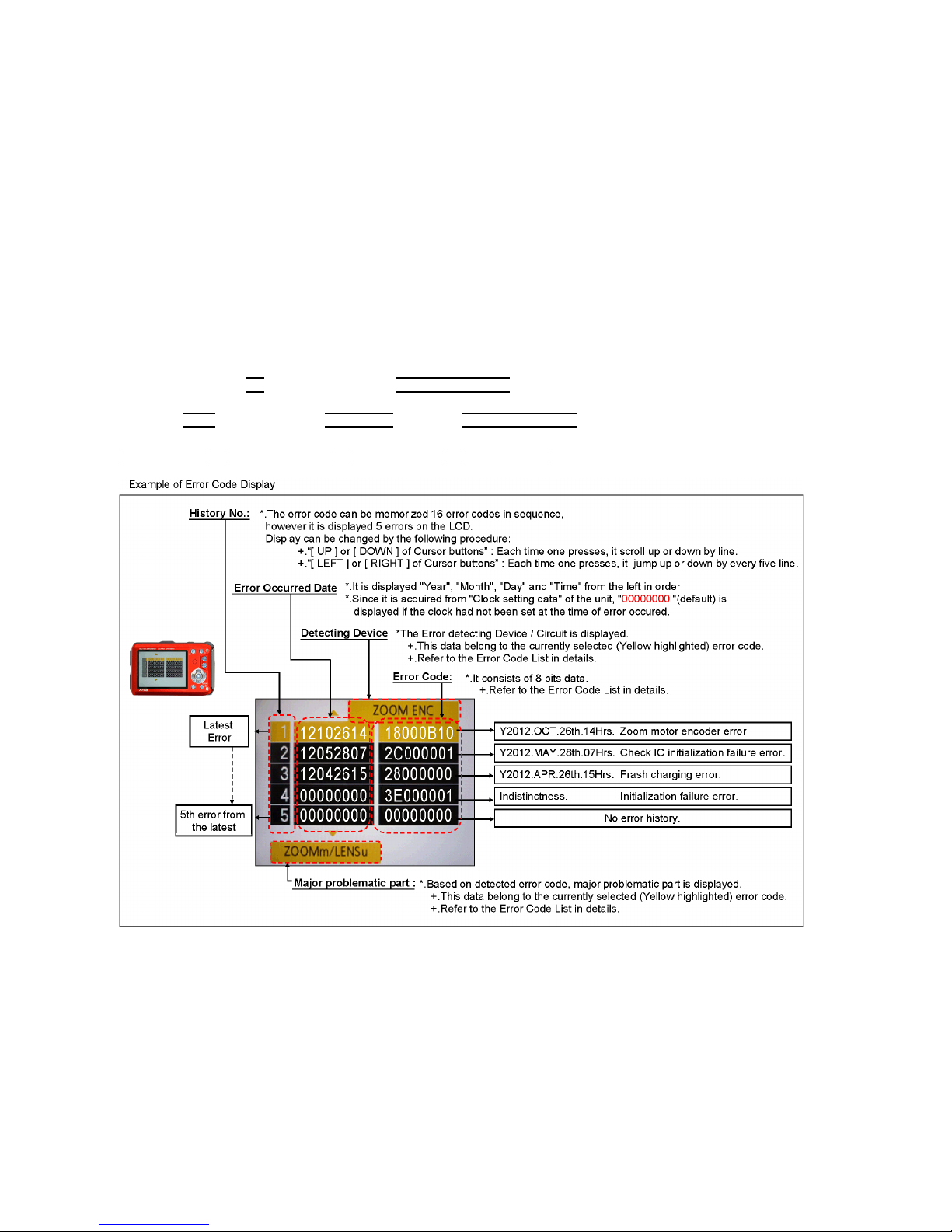
6.1. Error Code Memory Function
1. General description
This unit is equipped with history of error code memory function, and can be memorized 16 error codes in sequence from the
latest. When the error is occurred more than 16, the oldest error is overwritten in sequence.
The error code is not memorized when the power supply is shut down forcibly (i.e.,when the unit is powered on by the battery,
the battery is pulled out) The error code is memorized to FLASH ROM when the unit has just before powered off.
2. How to display
The error code can be displayed by ordering the following procedure:
• Preparation:
1. Attach the Battery to the unit.
Note:
*Since this unit has built-in memory, it can be performed without inserting SD memory card.
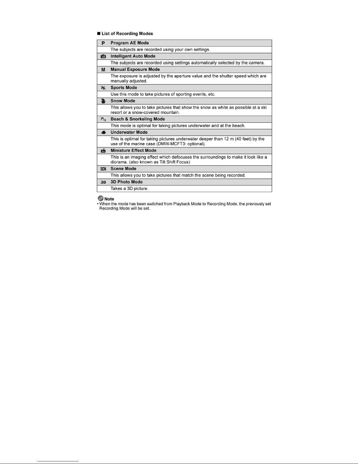
*Select the mode other than "3D" mode (such as Program AE / iA / Sports / Snow / SCN)
to display the error code.
• Step 1. The temporary cancellation of "INITIAL SETTINGS":
While keep pressing "UP
of Cursor button" and MOTION PICTURE button simultaneously, turn the Power on.
• Step 2. Execute the error code display mode:
Press the "LEFT
of Cursor button", MENU/SET button and MOTION PICTURE button simultaneously.
The display is changed as shown below when the above buttons are pressed simultaneously.
Normal display
→ Error code display → CAMERA INFO → Normal display → .....
23
3. Error Code List
The error code consists of 8 bits data and it shows the following information.
Attribute Main item Sub item Error code Contents (Upper) Error Indication
High 4bits Low 4 bits Check point (Lower) Detecting
device
Part/Circuit
LENS Lens drive OIS 18*0 1000 PSD (X) error. Hall element (X axis) position detect
error in OIS unit.
OIS X LENSu NG
OIS Unit
2000 PSD (Y) error. Hall element (Y axis) position detect
error in OIS unit.
OIS Y
OIS Unit
3000 GYRO (X) error. Gyro (IC6301) detect error on Top
P. C .B .
GYRO X GYRO NG
IC6301 (Gyro element) or IC6001 (VENUS ENGINE)
4000 GYRO (Y) error. Gyro (IC6302) detect error on Top
P. C .B .
GYRO Y
IC6302 (Gyro element) or IC6001 (VENUS ENGINE)
5000 MREF error (Reference voltage error). OIS REF LENSSd/DSP
NG
IC9101 (LENS DRIVE) or IC6001 (VENUS ENGINE)
6000 Drive voltage (X) error. OISX REF LENSu/LENS
FPC
LENS Unit, LENS flex breaks, IC6001(VENUS
ENGINE) AD value error, etc.
7000 Drive voltage (Y) error. OISY REF
LENS Unit, LENS flex breaks, IC6001(VENUS
ENGINE) AD value error, etc.
Zoom 0?10 Collapsible barrel Low detect error
(Collapsible barrel encoder always detects Low.)
ZOOM L ZOOMm/
LENSu
Mechanical lock, FP9002-(40) signal line or IC6001
(VENUS ENGINE)
0?20 Collapsible barrel High detect error
(Collapsible barrel encoder always detects High.)
ZOOM H
Mechanical lock, FP9002-(40) signal line or IC6001
(VENUS ENGINE)
0?60 The zoom position jump is detected due to the
impact (i.e. drop.) to the camera occurs.
(No indication) (No indication)
Lens unit
Focus 0?01 HP High detect error
(Focus encoder always detects High, and not
becomes Low)
FOCUS L LENS FPC/
DSP
Mechanical lock, FP9002-(40) signal line or IC6001
(VENUS ENGINE)
0?02 HP Low detect error
(Focus encoder always detects Low, and not
becomes High)
FOCUS H
Mechanical lock, FP9002-(40) signal line or IC6001
(VENUS ENGINE)
Lens 18*1 0000 Power ON time out error. LENS DRV LENSu
Lens drive system
18*2 0000 Power OFF time out error.
Lens drive system
Adj.History OIS 19*0 2000 OIS adj. Yaw direction amplitude error (small) OIS ADJ OIS ADJ
3000 OIS adj. Pitch direction amplitude error (small)
4000 OIS adj. Yaw direction amplitude error (large)
5000 OIS adj. Pitch direction amplitude error (large)
6000 OIS adj. MREF error
7000 OIS adj. time out error
8000 OIS adj. Yaw direction off set error
9000 OIS adj. Pitch direction off set error
A000 OIS adj. Yaw direction gain error
B000 OIS adj. Pitch direction gain error
C000 OIS adj. Yaw direction position sensor error
D000 OIS adj. Pitch direction position sensor error
E000 OIS adj. other error

24
1) About "*" indication:
The third digit from the left is different as follows.
In case of 0 (example: 18 0
01000)
When the third digit from the left shows "0", this error occurred under the condition of INITIAL SETTINGS has been completed.
It means that this error is occurred basically at user side.
In case of 8 (example: 18 8
01000)
When the third digit from the left shows "8", this error occurred under the condition of INITIAL SETTINGS has been released.
(Example; Factory assembling-line before unit shipment, Service mode etc.)
It means that this error is occurred at service side.
2) About "?" indication: ("18*0 0?01" to "18*0 0?50"):
The third digit from the right shows one of the hexadecimal ("0" to "F") character.
HARD VENUS A/DFlash 28*0 0000 Flash charging error. STRB CHG Flash CON
P.C.B./FPC
IC6001-(AC16) signal line or Flash charging circuit
FLASH
ROM
(EEPROM
Area)
FLASH
ROM
(EEPROM
Area)
2B*0 0001
0003
0004
EEPROM read error FROM RE FROM
IC6002 (FLASH ROM)
0002 EEPROM write error FROM WR FROM
IC6002 (FLASH ROM)
0005 Firmware version up error (No indication) (No indication)
Replace the firmware file in the SD memory card.
0008 SDRAM error
0009 SDRAM Mounting defective
SYSTEM RTC 2C*0 0001 SYSTEM IC initialize failure error SYS INIT Main P.C.B.
Communication between IC6001 (VENUS ENGINE)
and IC9101 (SYSTEM)
SOFT CPU Reset 30*0 0001
|
0007
NMI reset
Non Mask-able Interrupt
(30000001-30000007 are caused by factors)
NMI RST Main P.C.B.
Card Card 31*0 0001 Card logic error SD CARD SD CARD/
DSP
SD memory card data line or IC6001 (VENUS
ENGINE)
0002 Card physical error
SD memory card data line or IC6001 (VENUS
ENGINE)
0004 Write error SD WRITE
SD memory card data line or IC6001 (VENUS
ENGINE)
39*0 0005 Format error INMEMORY FROM
CPU,
ASIC hard
Stop 38*0 0001 Camera task finish process time out. LENS COM LENSu/DSP
Communication between Lens system and IC6001
(VENUS ENGINE)
0002 Camera task invalid code error. DSP DSP
IC6001 (VENUS ENGINE)
0100 File time out error in recording motion image
IC6001 (VENUS ENGINE)
0200 File data cue send error in recording motion image
IC6001 (VENUS ENGINE)
0300 Single or burst recording brake time out.
Memory
area
3A*0 0008 USB work area partitioning failure (No indication) (No indication)
USB dynamic memory securing failure when
connecting
Operation Power on 3B*0 0000 FLASHROM processing early period of camera
during movement.
INIT (No indication)
Zoom Zoom 3C*0 0000 Imperfect zoom lens processing ZOOM ZOOMm/
LENSu
Zoom lens
35*0 0000
|
FFFF
Software error
(0-7bit : command, 8-15bit : status)
DSP DSP
35*1 0000 Though record preprocessing is necessary, it is not
called.
35*2 0000 Though record preprocessing is necessary, it is not
completed.
(No indication) (No indication)
Attribute Main item Sub item Error code Contents (Upper) Error Indication
High 4bits Low 4 bits Check point (Lower) Detecting
device
Part/Circuit
25
4. How to returned to Normal Display:
Turn the power off and on, to exit from Error code display mode.
Note:
The error code can not be initialized.
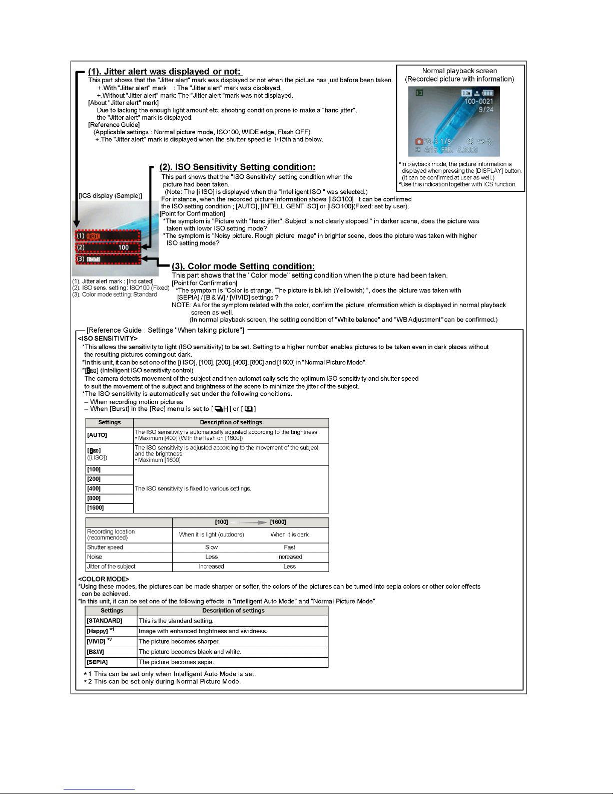
6.2. ICS (Indication of additional Camera Settings when picture was taken)
function
1. General description
This unit is equipped with ICS (ICS: I
ndication of additional Camera Settings when picture was taken) function by playing back the
concerned picture on the LCD display.
(This function is achieved by utilizing "maker note" data stored in Exif data area of recorded picture file.)
To proceed failure diagnosis, use this ICS function together with "displaying the recorded picture with picture information" function.
Note:
*.The ICS function operates with a picture which is only taken with the same model. (It may not be displayed when the picture
was taken with other model.)
*.Since Exif data is not available after the picture is edited by PC, the ICS function may not be activated.
2. How to display
The ICS data is displayed by ordering the following procedure:
• Preparation:
1.Attach the Battery to the unit.
Note:
*Select the mode other than "3D "mode (such as Program AE / iA / Sports / Snow / SCN) to display the ICS data.
• Step 1. The temporary cancellation of "INITIAL SETTINGS":
While keep pressing "UP
of Cursor button" and MOTION PICTURE button simultaneously, turn the Power on.
• Step 2. Execute the ICS display mode:
Press the PLAYBACK button.
Select the concerned picture by pressing the "LEFT
and RIGHT of Cursor button".
Press the "LEFT
of Cursor button", MENU/SET button and MOTION PICTURE button simultaneously.
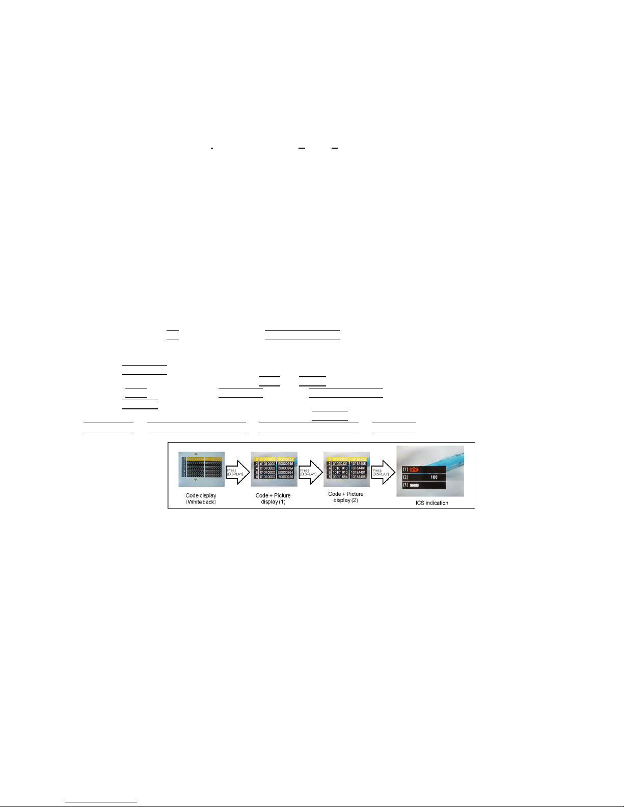
Press the DISPLAY
button, 3 times.
The display condition is changed as shown below when the DISPLAY
button is pressed.
Code display
→ Code + Picture display (1) → Code + Picture display (2) → ICS display → .....
26
3. How to read
4. How to exit
Simply, turn the power off. (Since ICS function is executed under the condition of temporary cancellation of "INITIAL SETTINGS",it
wake up with normal condition when turn off the power.)
27
7 Troubleshooting Guide
7.1. Service and Check Procedures
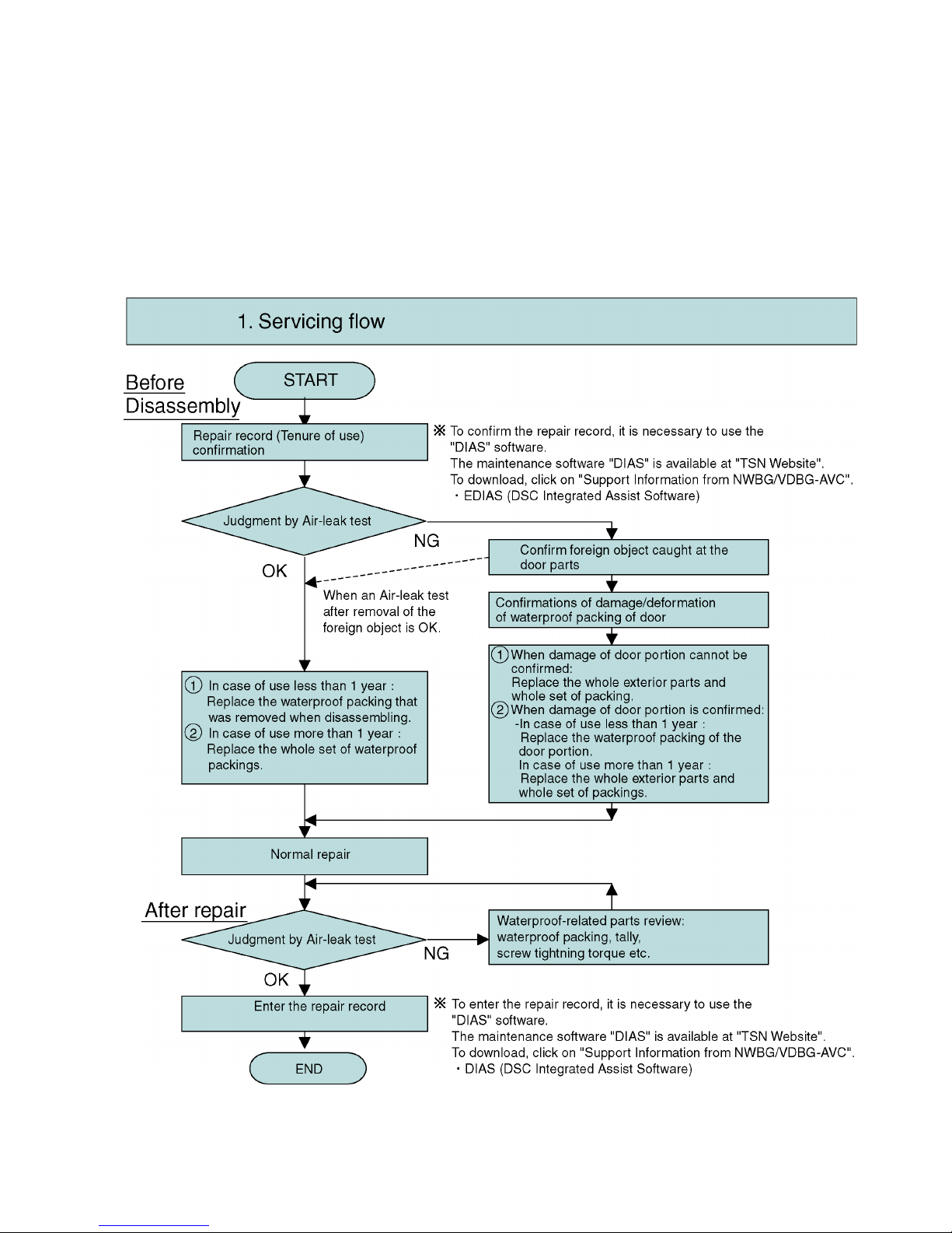
7.1.1. Servicing flow
• The following is the servicing procedure including assembly/disassembly process.
• As for the air-leak test, refer to "7.2. Air-leak Test".
< Note >
Air-leak test (inspection) before taking service measure:
• When the first inspection, do not perform cleaning (removal of foreign objects caught etc.) of the waterproof packing parts
(battery door and Jack door) from the viewpoint of the cause investigation at NG of test (inspection) result.
• When the test (inspection) result was NG, perform test again after cleaning of waterproof packing parts.
28
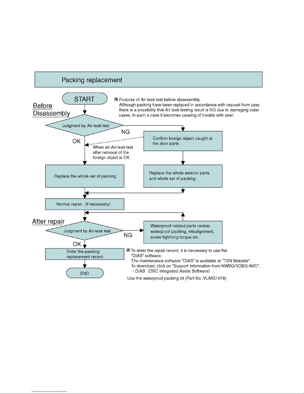
7.1.2. Periodical maintenance (Packing replacement) flow
• The integrity of the waterproof packings may decrease about 1 year, with use and age.
(We recommend end-users to replace the waterproof packing at least once each year described in the operating instructions.)
• Please use waterproof packing kit (Part No.: VUMG1978). (5 types, 8 packings in total are included)
• Do not touch the waterproof packings directly by the hand.
• Do not perform cleaning of waterproof packings by the solvent of alcohol etc. or by blowing air.
• Take care not to put any foreign objects (garbage and dust).
• As for the air-leak test, refer to "7.2. Air-leak Test".
29
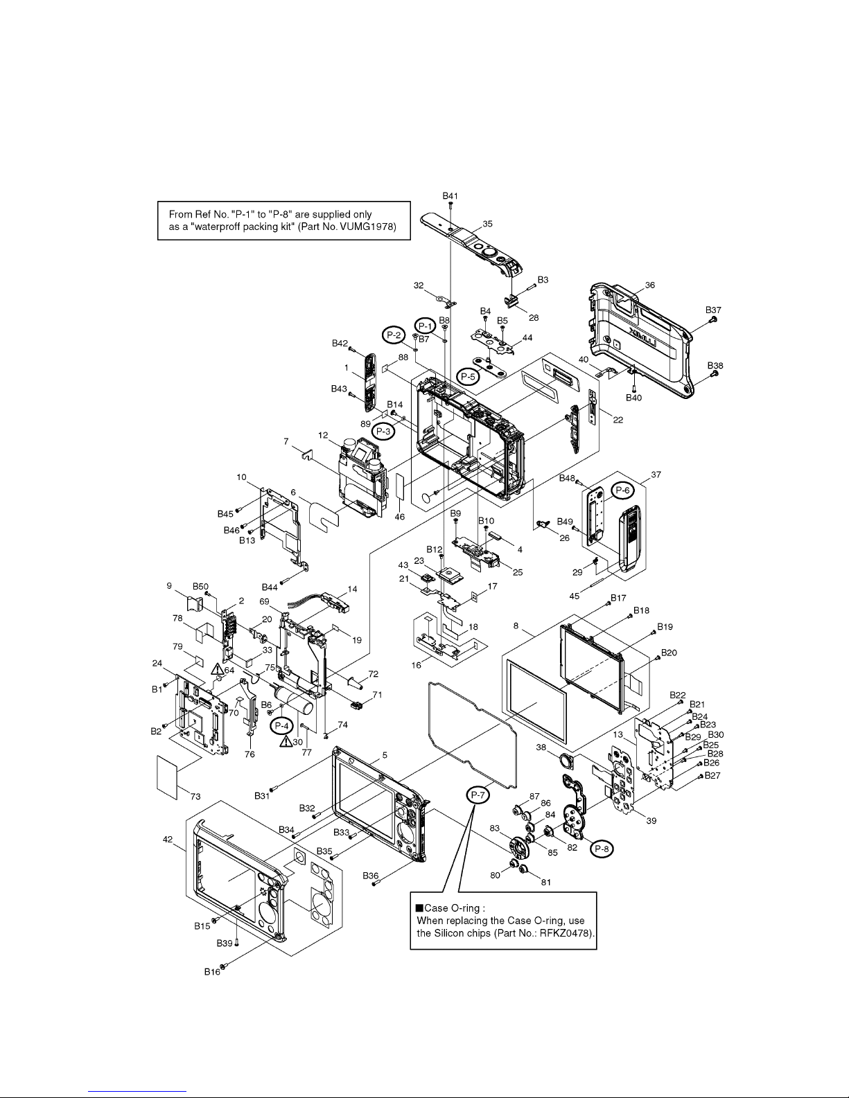
Replacing the waterproof packing
• The location of waterproof packing are shown at right. (5 types, 8 packings in total)
• Waterproof packings are supplied as Waterproof packing kit (Part No.: VUMG1978).
< Note for replacement >
• Do not touch the waterproof packings directly by the hand.
• Do not perform cleaning of waterproof packings by the solvent of alcohol etc. or by blowing air.
• Take care not to put any foreign objects (garbage and dust).
• Use the silicon chips (Part No.: RFKZ0478) when replacing the Case O-ring.

30
7.2. Air-leak Test
Due to the waterproof performance retention, perform the air-leak test using Air-leak tester (Part No.:RFKZ0528) before/after
servicing when disassembling and assembling the unit.
*The Air-leak test before servicing is necessary to be performed to check whether the malfunction occurred due to air-leak or not.
1. Preparation:
1) By referring the "9.3. Disassembly procedures", remove the side ornament (R) and front aluminum case.
2) Confirm that no foreign objects at the side door, and it is firmly closed.
2. Air-leak Test (Inspection):
*Perform the air-leak test by referring the following procedure.
Note:
As for the detail instruction of air-leak tester, refer to the operating guide (attached to the product).
[Preparation]
1. Put the camera with the top case facing upward condition.
2. Set the following measurement pressure value on the air-leak tester. (Part No.:RFKZ0528).
*About the Setting methods, refer to the operating guide for air-leak tester.
3. Attach "L" size of absorption pad to the tip of the hose of the air-leak tester.
4. Put the absorption pad of air-leak tester vertically on the Microphone part.
Note:
• Keep firmly hold above condition until the measurement is completed.
Once pad is tilted/misaligned from the test hole during testing process, start it from this step.
 Loading...