

Page 1

ORDER NO. DSC1002017CE
Digital Camera
Model No. DMC-F3P
DMC-F3PC
DMC-F3PR
DMC-F3PU
DMC-F3EB
DMC-F3EE
DMC-F3EF
B26
DMC-F3EG
DMC-F3EP
DMC-F3GC
DMC-F3GF
DMC-F3GN
DMC-F3GT
DMC-F4EB
DMC-F4EE
DMC-F4EG
DMC-F4EP
Colour
[ DMC-F3 ]
(S)...........Silver Type (except PC/EF/GT)
(K)...........Black Type
(P)...........Pink Type (except PC)
[ DMC-F4 ]
(S)...........Silver Type (only EE)
(K)...........Black Type (except EE)
© Panasonic Corporation 2010 Unauthorized copying and distribution is a violation of law.
Page 2

TABLE OF CONTENTS
PAGE PAGE
1 Safety Precautions -----------------------------------------------3
1.1. General Guidelines ----------------------------------------3
1.2. Leakage Current Cold Check ---------------------------3
1.3. Leakage Current Hot Check (See Figure 1.)--------3
1.4. How to Discharge the Capacitor on Flash
P.C.B.----------------------------------------------------------4
2Warning--------------------------------------------------------------5
2.1. Prevention of Electrostatic Discharge (ESD)
to Electrostatically Sensitive (ES) Devices ----------5
2.2. How to Recycle the Lithium Ion Battery (U.S.
Only)-----------------------------------------------------------5
2.3. Caution for AC Cord(For EB/GC) ----------------------6
2.4. How to dispose the Lithium Battery -------------------7
3 Service Navigation------------------------------------------------8
3.1. Introduction --------------------------------------------------8
3.2. General Description About Lead Free Solder
(PbF) ----------------------------------------------------------8
3.3. Important Notice 1:-----------------------------------------9
3.4. How to Define the Model Suffix (NTSC or PAL
model)-------------------------------------------------------10
4 Specifications----------------------------------------------------16
5 Location of Controls and Components------------------17
6 Service Fixture & Tools---------------------------------------19
6.1. Service Fixture and Tools------------------------------19
7 Disassembly and Assembly Instructions---------------21
7.1. Disassembly Flow Chart--------------------------------21
7.2. PCB Location----------------------------------------------21
7.3. Disassembly Procedure--------------------------------22
8 Measurements and Adjustments --------------------------27
8.1. Introduction ------------------------------------------------27
8.2. Matrix chart (Replaced part and Adjustment
item) ---------------------------------------------------------27
8.3. Execute the Adjustment software
“DscCalDi.exe”.-------------------------------------------28
8.4. Adjustment procedures---------------------------------29
9 Maintenance ------------------------------------------------------38
9.1. Cleaning Lens and LCD Panel -----------------------38
10 Block Diagram ---------------------------------------------------39
10.1. Overall Block Diagram----------------------------------39
11 Wiring Connection Diagram---------------------------------40
12 Printed Circuit Board ------------------------------------------41
12.1. Fuse location on MAIN P.C.B. ------------------------41
2
Page 3
1 Safety Precautions
1.1. General Guidelines
1. IMPORTANT SAFETY NOTICE
There are special components used in this equipment
which are important for safety. These p art s are marked by
in the Schematic Diagrams, Circuit Board Layout,
Exploded Views and Replacement Parts List. It is essential that these critical parts should be replaced with manufacturer’s specified parts to prevent X-RADIATION,
shock, fire, or other hazards. Do not modify the original
design without permission of manufacturer.
2. An Isolation Transformer should always be used during
the servicing of AC Adaptor whose chassis is not isolated
from the AC power line. Use a transformer of adequate
power rating as this protects the technician from accidents resulting in personal injury from electrical shocks. It
will also protect AC Adaptor from being damaged by accidental shorting that may occur during servicing.
3. When servicing, observe the original lead dress. If a short
circuit is found, replace all parts which have been overheated or damaged by the short circuit.
4. After servicing, see to it that all the protective devices
such as insulation barriers, insulation papers shields are
properly installed.
5. After servicing, make the following leakage current
checks to prevent the customer from being exposed to
shock hazards.
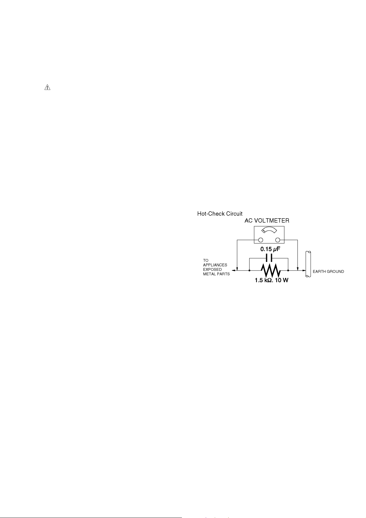
1.3. Leakage Current Hot Check
(See Figure 1.)
1. Plug the AC cord directly into the AC outlet. Do not use
an isolation transformer for this check.
2. Connect a 1.5 kΩ, 10 W resistor, in parallel with a 0.15 μF
capacitor, between each exposed metallic part on the set
and a good earth ground, as shown in Figure 1.
3. Use an AC voltmeter, with 1 kΩ/V or more sensitivity, to
measure the potential across the resistor.
4. Check each exposed metallic part, and measure the voltage at each point.
5. Reverse the AC plug in the AC outlet and repeat each of
the above measurements.
6. The potential at any point should not exceed 0.75 V RMS.
A leakage current tester (Simpson Model 229 or equivalent) may be used to make the hot checks, leakage current must not exceed 1/2 mA. In case a measurement is
outside of the limits specified, there is a possibility of a
shock hazard, and the equipment should be repaired and
rechecked before it is returned to the customer.
1.2. Leakage Current Cold Check
1. Unplug the AC cord and connect a jumper between the
two prongs on the plug.
2. Measure the resistance value, with an ohmmeter,
between the jumpered AC plug and each exposed metallic cabinet part on the equipment such as screwheads,
connectors, control shafts, etc. When the exposed metallic part has a return path to the chassis, the reading
should be between 1 MΩ and 5.2 MΩ. When the exposed
metal does not have a return path to the chassis, the
reading must be infinity.
Figure. 1
3
Page 4
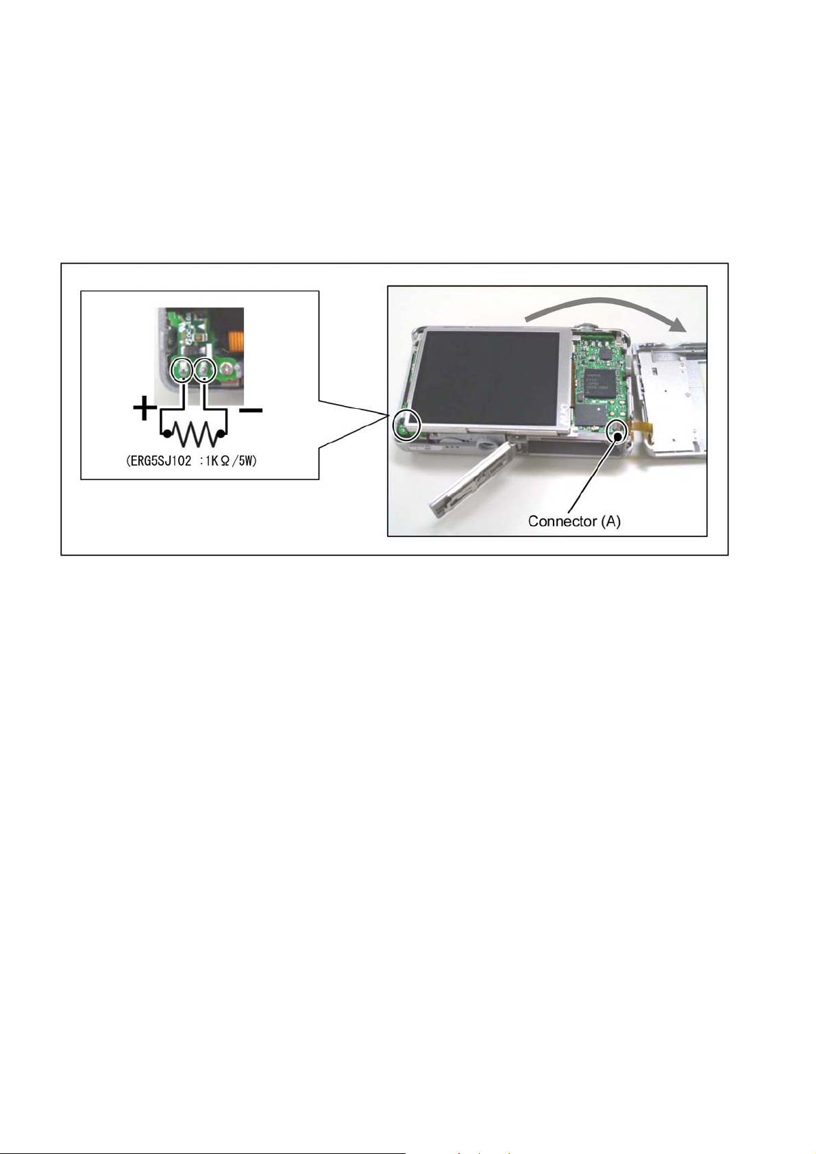
1.4. How to Discharge the Capacitor on Flash P.C.B.
CAUTION:
1. Make sure to discharge the capacitor on FLASH P.C.B..
2. Be careful of the high voltage circuit on FLASH P.C.B. when servicing.
[Discharging Procedure]
1. Refer to the disassemble procedure and remove the necessary parts/unit.
2. Install the insulation tube onto the lead part of resistor (ERG5SJ102:1kΩ /5W).
(an equivalent type of resistor may be used.)
3. Place a resistor between both terminals of capacitor on the FLASH P.C.B. for approx. 5 seconds.
4. After discharging, confirm that the capacitor voltage is lower than 10V using a voltmeter.
Fig. F1
4
Page 5

2Warning
2.1. Prevention of Electrostatic Discharge (ESD) to Electrostatically
Sensitive (ES) Devices
Some semiconductor (solid state) devices can be damaged easily by static electricity. Such components commonly are called Electrostatically Sensitive (ES) Devices.
The following techniques should be used to help reduce the incidence of compon ent damage caused by electrostatic discharge
(ESD).
1. Immediately before handling any semiconductor component or semiconductor-equipped assembly, drain off any ESD on your
body by touching a known earth ground. Alternatively, obtain and wear a commercially available discharging ESD wrist strap,
which should be removed for potential shock reasons prior to applying power to the unit under test.
2. After removing an electrical assembly equipped with ES devices, place the assembly on a condu ctive surface such as al uminum foil, to prevent electrostatic charge buildup or exposure of the assembly.
3. Use only a grounded-tip soldering iron to solder or unsolder ES devices.
4. Use only an antistatic solder removal device. Some solder removal devices not classified as "antistatic (ESD protected)" can
generate electrical charge sufficient to damage ES devices.
5. Do not use freon-propelled chemicals. These can generate electrical charges sufficient to damage ES devices.
6. Do not remove a replacement ES device from its protective package until immediately before you are ready to install it. (Most
replacement ES devices are packaged with leads electrically shorted together by conductive foam, aluminum foil or comparable conductive material).
7. Immediately before removing the protective material from the leads of a replacement ES device, touch the protective material
to the chassis or circuit assembly into which the device will be installed.
CAUTION :
Be sure no power is applied to the chassis or circuit, and observe all other safety precautions.
8. Minimize bodily motions when handling unpackaged replacement ES devices. (Otherwise harmless motion such as the
brushing together of your clothes fabric or the lifting of your foot from a carpeted floor can generate static electricity (ESD) sufficient to damage an ES device).
2.2. How to Recycle the Lithium Ion Battery (U.S. Only)
5
Page 6
2.3. Caution for AC Cord
(For EB/GC)
2.3.1. Information for Your Safety
IMPORTANT
Your attention is drawn to the fact that recording of prerecorded tapes or discs or other published or broadcast
material may infringe copyright laws.
WARNING
To reduce the risk of fire or shock hazard, do not expose
this equipment to rain or moisture.
CAUTION
To reduce the risk of fire or shock hazard and annoying
interference, use the recommended accessories only.
FOR YOUR SAFETY
DO NOT REMOVE THE OUTER COVER
To prevent electric shock, do not remove the cover. No user
serviceable parts inside. Refer servicing to qualified service
personnel.
2.3.2. Caution for AC Mains Lead
For your safety, please read the following text carefully.
This appliance is supplied with a moulded three-pin mains plug
for your safety and convenience.
A 5-ampere fuse is fitted in this plug.
Should the fuse need to be replaced please ensure that the
replacement fuse has a rating of 5 amperes and it is approved
by ASTA or BSI to BS1362
Check for the ASTA mark or the BSI mark on the body of the
fuse.
2.3.2.1. Important
The wires in this mains lead are coloured in accordance with
the following code:
Blue Neutral
Brown Live
As the colours of the wires in the mains lead of this appliance
may not correspond with the coloured markings i dentifying the
terminals in your plug, proceed as follows:
The wire which is coloured BLUE must be connected to the terminal in the plug which is marked with th e letter N or coloured
BLACK.
The wire which is coloured BROWN must be connected to the
terminal in the plug which is marked with the letter L or coloured
RED.
Under no circumstances should either of these wires be connected to the earth terminal of the three pin plug, marked with
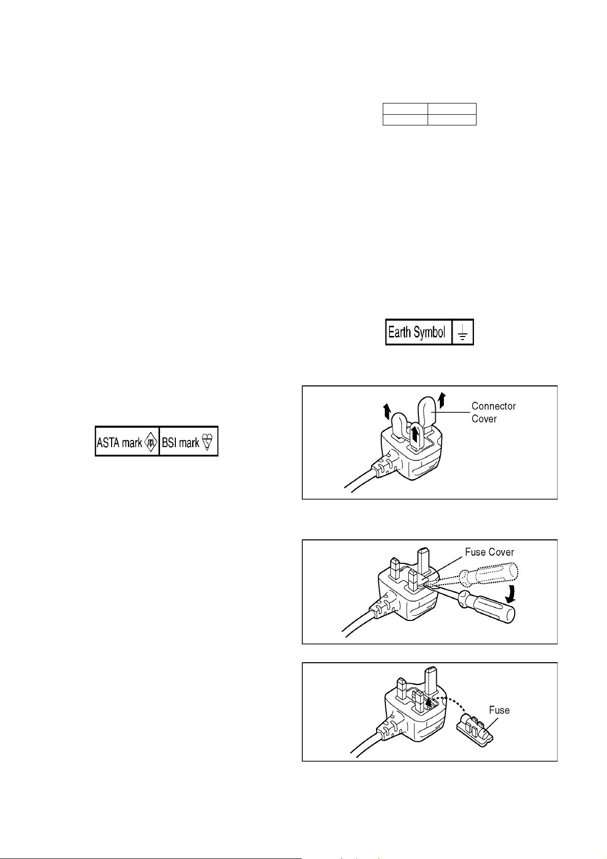
the letter E or the Earth Symbol.
2.3.2.2. Before Use
Remove the Connector Cover as follows.
If the plug contains a removable fuse cover you must ensure
that it is refitted when the fuse is replaced.
If you lose the fuse cover, the plug must not be used until a
replacement cover is obtained.
A replacement fuse cover can be purchased from your local
Panasonic Dealer.
If the fitted moulded plug is unsuitable for the socket outlet in
your home then the fuse should be removed and the plug cut
off and disposed of safety.
There is a danger of severe electrical shock if the cut off plug is
inserted into any 13-ampere socket.
If a new plug is to be fitted please observe the wiring code as
shown below.
If in any doubt, please consult a qualified electrician.
2.3.2.3. How to Replace the Fuse
1. Remove the Fuse Cover with a screwdriver.
2. Replace the fuse and attach the Fuse cover.
6
Page 7
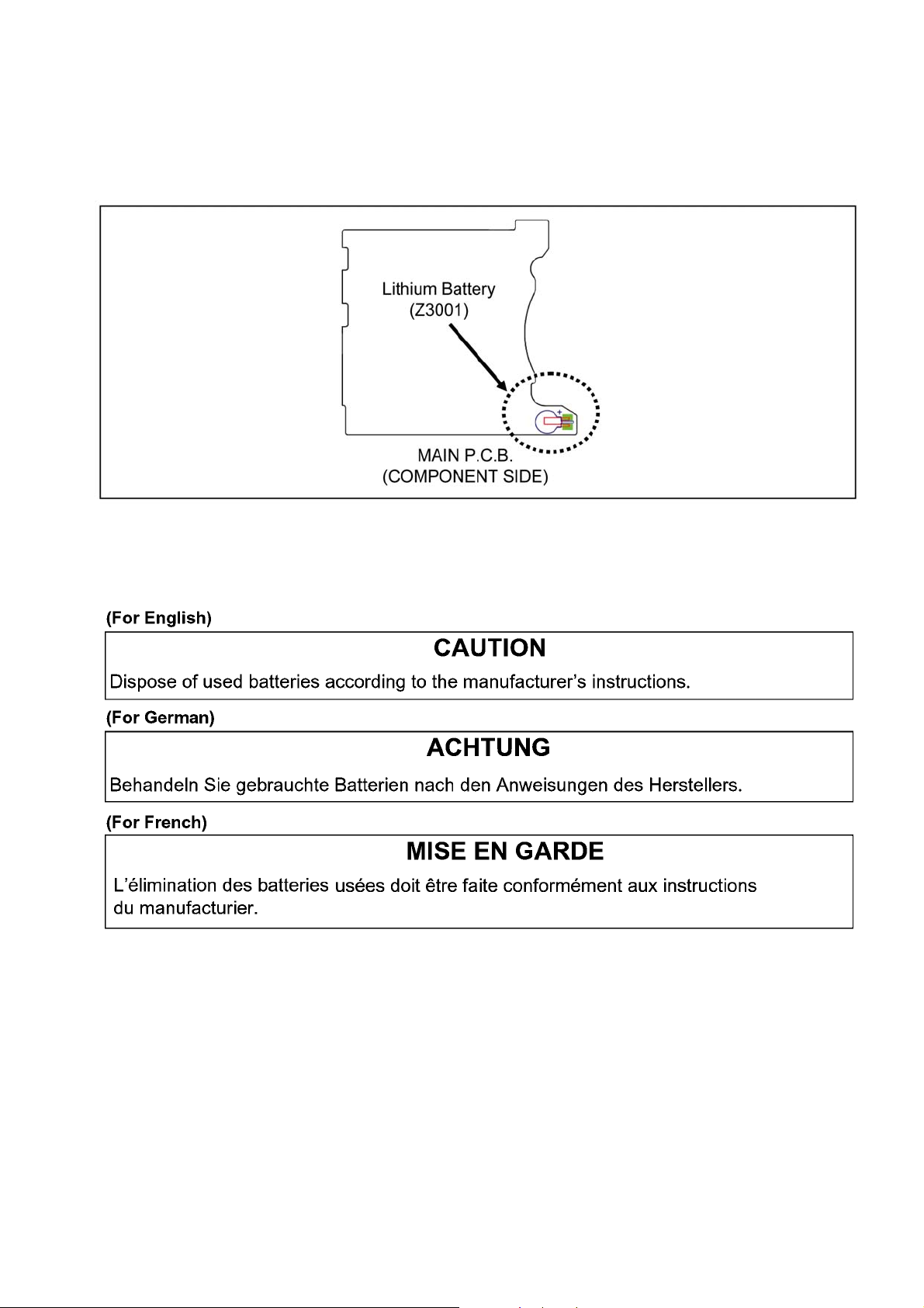
2.4. How to dispose the Lithium Battery
2.4.1. Removal Procedure
1. Remove the Main P.C.B. (Refer to Disassembly Procedures.)
2. Remove the Lithium battery (Ref. No.“Z3001” at component side of Main P.C.B.) and then dispose it.
It should be disposed of in waste products destined for burial rather than incineration.
NOTE:
This Lithium battery is a critical component.
It must never be subjected to excessive heat or discharge.
It should be disposed of in waste products destined for burial rather than incineration.
NOTE:
Above caution is applicable for a battery pack which is for DMC-F3/F4 series, as well.
7
Page 8

3 Service Navigation
3.1. Introduction
This service manual contains technical information, which allow service personnel’s to understand and service this model.
Please place orders using the parts list and not the drawing reference numbers.
If the circuit is changed or modified, the information will be followed by service manual to be controlled with original service manual.
3.2. General Description About Lead Free Solder (PbF)
The lead free solder has been used in the mounting process of all electrical comp onents on the printed circuit boards us ed for this
equipment in considering the globally environmental conservation.
The normal solder is the alloy of tin (Sn) and lead (Pb). On the other hand, the lead free solder is the alloy mainly consists of tin
(Sn), silver (Ag) and Copper (Cu), and the melting point of the lead free solder is higher approx.30°C (86°F) more than that of the
normal solder.
Distinction of P.C.B. Lead Free Solder being used
Service caution for repair work using Lead Free Solder (PbF)
• The lead free solder has to be used when repairing the equipment for which the lead free solder is used.
(Definition: The letter of “PbF” is printed on the P.C.B. using the lead free solder.)
• To put lead free solder, it should be well molten and mixed with the original lead free solder.
• Remove the remaining lead free solder on the P.C.B. cleanly for soldering of the new IC.
• Since the melting point of the lead free solder i s higher than that of the normal lead solder, it takes the longer time to melt the
lead free solder.
• Use the soldering iron (more than 70W) equipped with the temperature control after setting the temperature at 350±30°C
(662±86°F).
Recommended Lead Free Solder (Service Parts Route.)
• The following 3 types of lead free solder are available through the service parts route.
RFKZ03D01KS-----------(0.3mm 100g Reel)
RFKZ06D01KS-----------(0.6mm 100g Reel)
RFKZ10D01KS-----------(1.0mm 100g Reel)
Note
* Ingredient: tin (Sn) 96.5%, silver (Ag) 3.0%, Copper (Cu) 0.5%, Cobalt (Co) / Germanium (Ge) 0.1 to 0.3%
8
Page 9
3.3. Important Notice 1:
[1.Component on P.C.B.]
1. The P.C.B.’s in this unit is not component replacement excluding following part.
MAIN P.C.B. --------- Fuse (F5001, F5002, F5005, F5006)
FLASH P.C.B. -------- Flash Charging Capacitor(C5412)), Trigger Coil(T5402)
Other than above component on P.C.B.’s are defected, replace each P.C.B. as a unit.
[2.MAIN P.C.B.]
AFTER REPLACING THE MAIN P.C.B.
After replacing the Main P.C.B., follow the following steps in order.
1. Assemble the unit.
Refer to the “7.Disassembly and Assembly Instructions” section.
2. Up date the firmware.
The firmware together with version up procedure are available at “software download” on the “Support Information from
NWBG/VDBG-AVC” web-site in “TSN system”.
3. Perform the adjustment using adjustment software “DscCalDi”.
The adjustment software is available at “software download” on the “Support Information from NWBG/VDBG-AVC” web-site in
“TSN system”.
4. Register the USB storage information.
Refer to the “8.4.6.USB STORAGE INFO. REGISTRATION” in “8.4.Adjustment procedures” section.
5. Set the “model suffix”.
Refer to the “3.4.2.INITIAL SETTINGS:” section.
6. Refresh the unit.
Refer to the “3.4.2.INITIAL SETTINGS:” section.
[3.Lens unit]
1. The Lens unit in this unit is not component replacement.
Other than above part are defected, replace minimumsize of concerned part as a unit.
9
Page 10
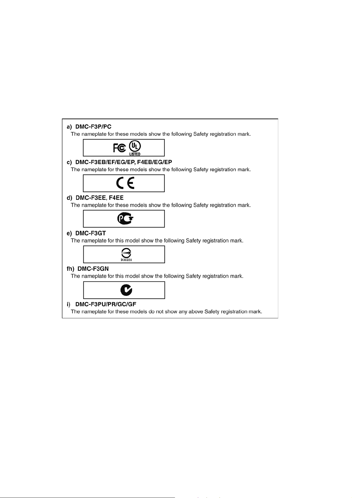
3.4. How to Define the Model Suffix (NTSC or PAL model)
There are six kinds of DMC-F3/F4, regardless of the colours.
• a) DMC-F3P/PC
• b) DMC-F3EB/EF/EG/EP, F4EB/EG/EP
• c) DMC-F3EE, F4EE
• d) DMC-F3GT
• e) DMC-F3GN
• f) DMC-F3PU/PR/GC/GF
What is the difference is that the “INITIAL SETTINGS” data which is stored in Flash-ROM mounted on MAIN P.C.B..
3.4.1. Defining methods:
To define the model suffix to be serviced, refer to the nameplate which is putted on the bottom side of the Unit.
NOTE:
After replacing the MAIN P.C.B., make sure to perform the “firmware version up”, “Initial settings” and “adjustment”.
The firmware & adjustment software is available at “software d ownload” on the “Support Info rmation from NWBG/VDBG-AVC”
web-site in “TSN system”.
10
Page 11
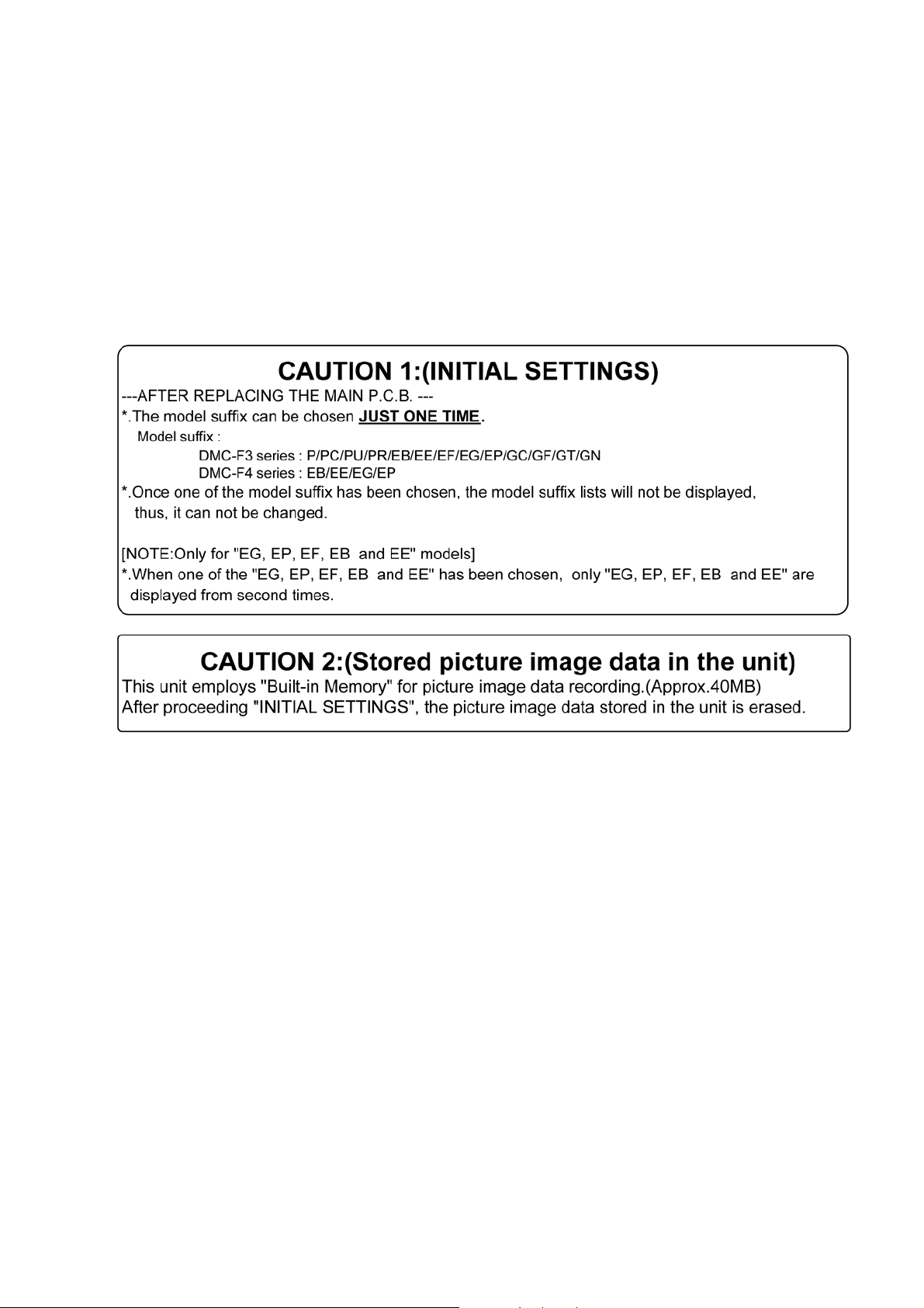
3.4.2. INITIAL SETTINGS:
1. PURPOSE OF INITIAL SETTINGS:
There are two cases to perform the INITIAL SETTINGS.
1. Refresh the unit:The INITIAL SETTINGS can be used to erase all back up data.
(Not only user setting and image data stored in “Built-in Memory”, but also clock data is reset.)
2. After replacing the MAIN P.C.B.:
(Since the model suffix data is not assigned for the MAIN P.C.B. being supplied as spare parts, model suffix has to be
assigned.)
After replacing the MAIN P.C.B., make sure to perform the “firmware version up”, “adjus tment” a nd “Ini ti al setting s ” by o rderi ng
the following procedure in accordance with model suffix of the unit.
2. IMPORTANT NOTICE:
Before proceeding Initial settings, make sure to read the following CAUTIONS.
3. PROCEDURES:
NOTE:
1. Precautions: Read the above “CAUTION 1” and “CAUTION 2”, carefully.
2. To perform the Initial settings, adjustment software “DscCalDi” is required. The software together with installation instruction is
available at “software download” on the “Support Information from NWBG/VDBG-AVC” web-site in “TSN system”.
Step 1. Preparation:
1. After replacing the MAIN P.C.B., assemble the unit by referring the “7.Disassembly and Assembly Instructions”.
2. Update the firmware of the unit.
The firmware together with version up procedure are available at “software download” on the “Support Information from
NWBG/VDBG-AVC” web-site in “TSN system”.
3. Perform the adjustment using adjustment software “DscCalDi”.
The adjustment software is available at “software download” on the “Support Information from NWBG/VDBG-AVC” web-site in
“TSN system”.
4. Register the USB storage information.
Refer to the “8.4.6.USB STORAGE INFO. REGISTRATION” in “8.4.Adjustment procedures” section.
11
Page 12
Step 2. Setup:
1. Attach the Battery or AC Adaptor with a DC coupler to the unit.
2. Set the [ REC/PLAY ] switch to “REC” mode.
3. Set the recording mode to [ Normal Picture ] mode.
*.Turn on the power switch and then press the “MODE” button.
*.Choose the [ Normal Picture ] mode with cursor buttons, then press the “MENU/SET” button.
*.Turn the power switch to OFF.
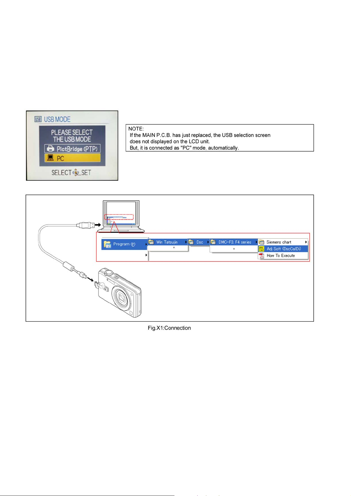
4. Connect the Camera unit and a PC with a USB cable.
5. Turn the power switch to ON.
6. Select the USB mode to “PC” mode, then press the “MENU/SET” button.
(NOTE: Right after replacing the MAIN P.C.B., the USB selection screen does not displayed.)
12
Page 13
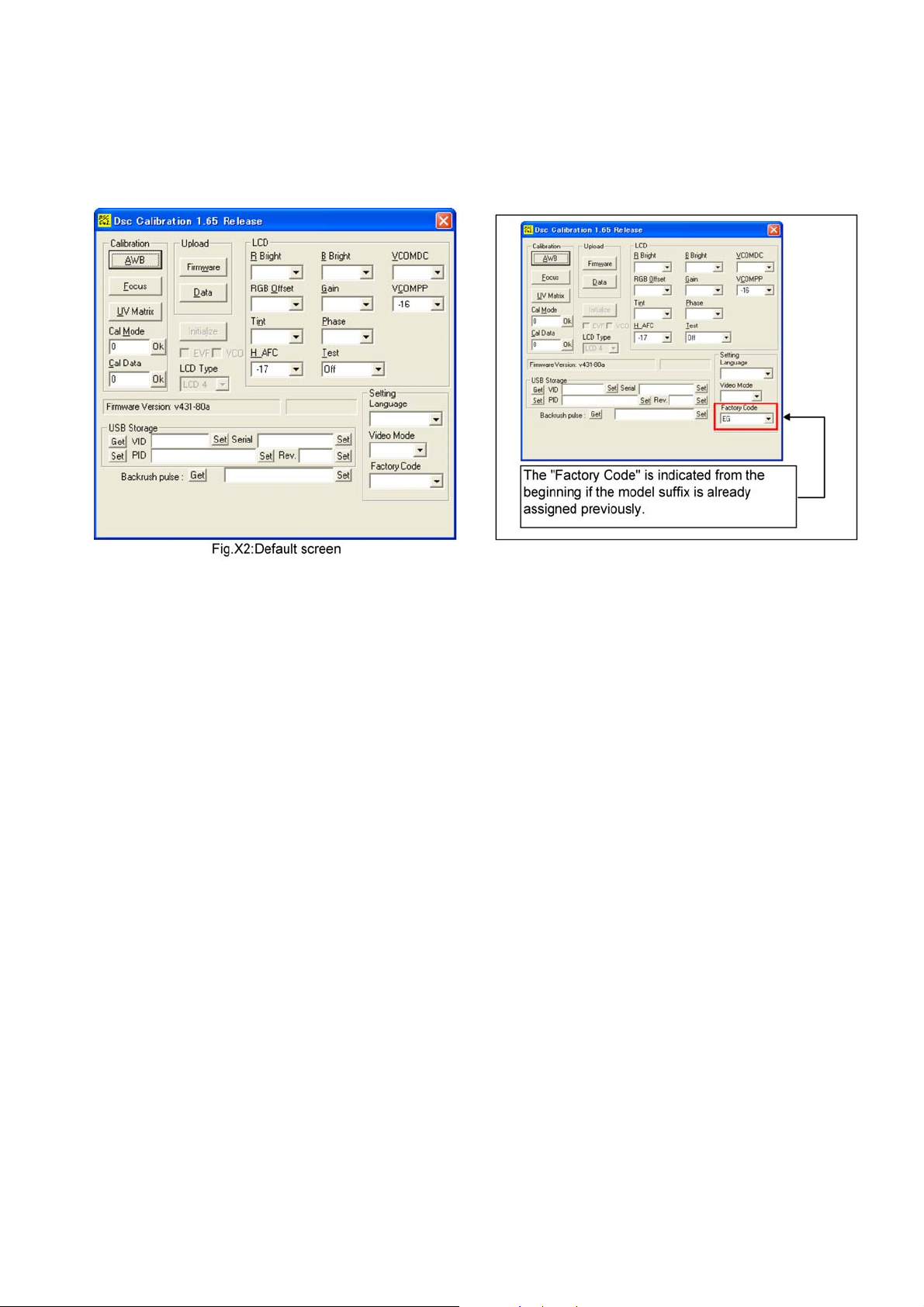
Step 3. Execute the software “DscCalDi” :
1. Choose the “Adj Soft (DscCalDi)” and execute the adjustment software.(Refe r to Fig.X1:Connection)
[ “Start” ---> “Program(P)” ---> “Win Tatsujin” ---> “Dsc” ---> “DMC-F3,F4 series” ---> “Adj Soft (DscCalDi)” ]
The following main screen is appear on the PC monitor.
NOTE:
Without connecting the USB cable between DSC (USB mode with power on) an d PC, adjustment software does no t executed.
13
Page 14
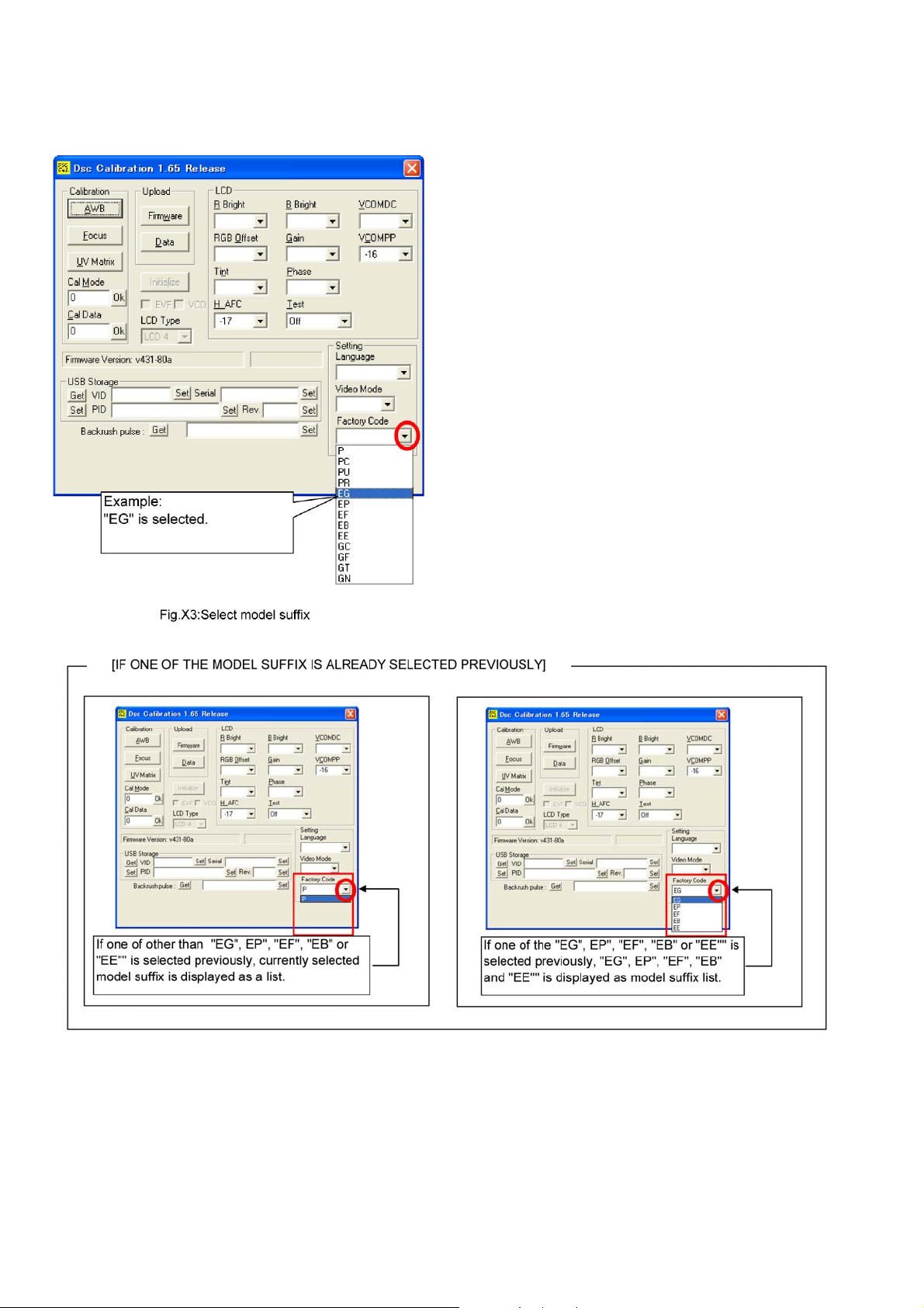
Step 4. Select the Model suffix (Factory Code):
1. Click on the pull down menu tag of the “Factory Code”.
The model suffix list is displayed.
2. Choose the appropriate model suffix.
14
Page 15
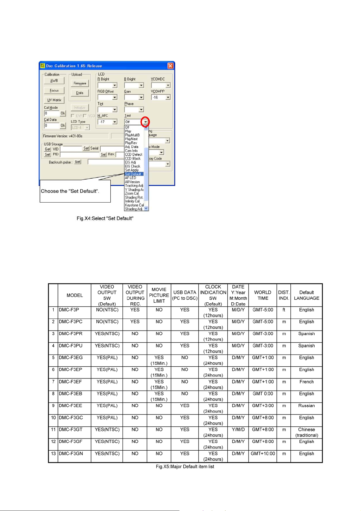
Step 5. Default settings (Test):
1. Click on the pull down menu tag of the “Test”.
(The Test item list is disp layed.)
2. Choose the “Set Default” in order to refresh the unit (Factory shipping condition).
Step 6. CONFIRMATION:
1. Close the “DscCalDi.exe” by clicking on the “X” located on the top right corner.
2. Turn on the camera switch.
3. Disconnect the USB cable and turn “OFF” the power switch of the camera unit.
4. Confirm that the language and Clock set request screen is displayed on the LCD monitor.
Major default setting condition is as shown in the following table.
15
Page 16

4 Specifications
16
Page 17

5 Location of Controls and Components
5
20
2122
18 19
Names of the Components
1Flash
2Lens
3 Self-timer indicator
AF assist lamp
4 Microphone
5 LCD monitor
6 [MENU/SET] button
7 [DISPLAY] button
8 [Q.MENU]/Delete button
9 [MODE] button
10 [REC]/[PLAYBACK] selector switch
11 Cursor buttons
: /Exposure compensation
: /Macro Mode
: /Self-timer button
: /Flash setting button
12 Camera ON/OFF switch
13 Zoom lever
14 Shutter button
15 Hand strap eyelet
Be sure to attach the hand strap when
using the camera to ensure that you will
not drop it.
16 Lens barrel
17 [AV OUT/DIGITAL] socket
123
4
5
9
68
7
1110
12 13
14
1
16
17
18 Speaker
19 Tripod receptacle
When you use a tripod, make sure the
tripod is stable when the camera is
attached to it.
20 Card/Battery door
21 Release lever
22 DC coupler cover
When using an AC adaptor, ensure that
the Panasonic DC coupler and AC adaptor
are used.
We recommend you use a battery with
sufficient battery power or the AC adaptor
when recording motion pictures.
If while recording motion pictures using the
AC adaptor and the power supply is cut off
due to a power outage or if the AC adaptor
is disconnected etc., the motion picture
being recorded will not be recorded.
17
Page 18

Selecting the [REC] Mode
ON
OFF
Turnthecameraon.
[MENU/SET] button
[REC]/[PLAYBACK] selector switch
[MODE] button
Slide the [REC]/[PLAYBACK]
selector switch to [].
Press [MODE].
Press / to select the mode.
Press [MENU/SET].
List of [REC] Modes
Auto Scene Mode
The subjects are recorded using settings automatically selected by the
camera.
Normal Picture Mode
The subjects are recorded using your own settings.
± Scene Mode
This allows you to take pictures that match the scene being recorded.
Motion Picture Mode
This mode allows you to record motion pictures with audio.
Preparation
About the Battery
The camera has a function for distinguishing batteries which can be used safely. The
dedicated battery supports this function. The only batteries suitable for use with this
unit are genuine Panasonic products and batteries manufactured by other companies
and certified by Panasonic. (Batteries which do not support this function cannot be
used.) Panasonic cannot in any way guarantee the quality, performance or safety of
batteries which have been
Panasonic products.
It has been found that counterfeit battery packs which look very similar to the
genuine product are made available to purchase in some markets. Some of these
battery packs are not adequately protected with internal protection to meet the
requirements of appropriate safety standards. There is a possibility that these
battery packs may lead to fire or explosion. Please be advised that we are not
liable for any accident or
battery pack. To ensure that safe products are used we would recommend that a
genuine Panasonic battery pack is used.
manufactured by other companies and are not genuine
failure occurring as a result of use of a counterfeit
18
Page 19

6 Service Fixture & Tools
6.1. Service Fixture and Tools
The following Service Fixture and tools are used for checking and servicing this unit.
19
Page 20

REMARKS
1. ABOUT “Siemens star chart”:
The PDF version of Siemens star chart together adjustment software is available at “software download” on the “Support Information from NWBG/VDBG-AVC” web-site in “TSN system”.
Download its PDF file and print out it, then stick on the suitable panel.
For your convenience, there are two kinds of PDF files are available.; “A3 size”(Full-size) / “Letter size”(Divided into 3 sheets).
If you have A3 size printer, print it out then stick on the suitable panel.
If you have not A3 size printer, print out “Letter size PDF” version, then make a Siemens star chart.
2. ABOUT “LIGHT BOX”:
20
Page 21

7 Disassembly and Assembly Instructions
7.1. Disassembly Flow Chart
This is a disassembling chart.
When assembling, perform this chart conversely.
7.2. PCB Location
21
Page 22

7.3. Disassembly Procedure
No. Item Fig Removal
1 Rear Case Unit (Fig.D1)
(Fig.D2)
2 LCD Unit (Fig.D3)
(Fig.D4)
3Flash P.C.B. &
Lens Unit
4 Front/Top Case Unit (Fig.D8)
5 Main P.C.B. &
Top Operation P.C.B. &
Battery Case Unit
6 CCD Unit (Fig.D12) 3 Screws (L)
(Fig.D5)
(Fig.D6)
(Fig.D7)
(Fig.D9a)
(Fig.D9b)
(Fig.D10)
(Fig.D11) 2 Screws (J)
Card
Battery
4 Screws (A)
1 Screw (B)
Connector (A)
3 Screws (C)
LCD Holder
Connector (B)
Flex Cable
2 Screws (D)
Lens Holder
Connector (C)
Connector (D)
Lens Unit
1 Screw (E)
1 Screw (F)
1 Screw (G)
1 Screw (H)
1 Screw (I)
Jack Door
AF LED P.C.B.
Earth bottom
Earth E.capacitor
Tripod stand
2 Screws (K)
Unsolder
CCD Cushion
Optical Filter
7.3.1. Removal of the Rear Case Unit
(Fig.D2)
(Fig.D1)
22
Page 23

7.3.2. Removal of the LCD Unit
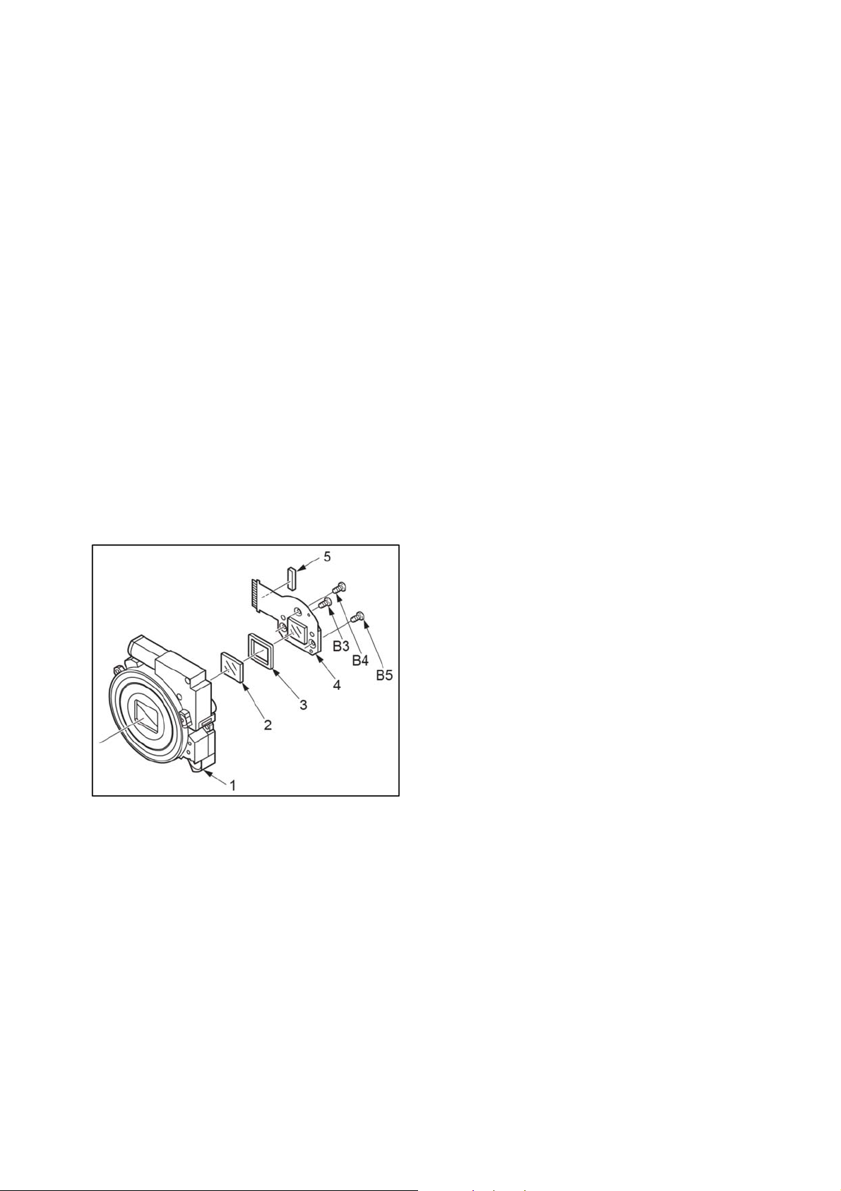
7.3.3. Removal of the Flash P.C.B. & Lens
Unit
(Fig.D3)
(Fig.D4)
(Fig.D5)
(Fig.D6)
23
Page 24

(Fig.D7)
7.3.4. Removal of the Front/Top Case Unit
(Fig.D8)
(Fig.D9a)
24
Page 25

7.3.5. Removal of the Main P.C.B. and Top
Operation P.C.B. & Battery Case
Unit
(Fig.D9b)
(Fig.D10)
(Fig.D11)
25
Page 26

7.3.6. Removal of the CCD Unit
NOTE:
1. Make sure no dust or dirt gets into the lens.
2. To remove dust from the lens, use airbrush.
3. Do not touch the surface of the lens.
4. Use lens cleaning KIT (BK) (VFK1900BK).
NOTE: (When Assembling)
[Definitions of mount side of Optical filter.]
• Put the Optical filter on the white sheet.
• When the "non -coating side is face up condition, it can be
seen as two-layered filter.
• Set the Coating (Green layer) side to lens side.
[Screwing Order]
• When installing the CCD unit to Lens unit with screw, tighten
the screws in the letters order.(A , B, C.)
NOTE: (When Assembling)
Make sure to confirm the following points when assembling:
• The Screw is tightened enough.
• Assembling conditions are fine. (No distortion, no abnormalspace.)
• No dust and/or dirt on Lens surfaces.
• LCD image is fine. (No dust and dirt on it, and no gradient
images.)
(Fig.D12)
26
Page 27

8 Measurements and Adjustments
8.1. Introduction
When servicing this unit, make sure to perform the adjustments necessary based on the part(s) replaced.
To perform the adjustment, it is necessary to use the “DscCalDi” software.
The Adjustment software “DscCalDi” together with its installation instruction are available at “TSN Website”.
To download, click on “Support Information from NWBG/VDBG-AVC”.
8.2. Matrix chart (Replaced part and Adjustment item)
The following matrix table shows the relation between the replaced part and the necessary adjustment.
When a part is replaced, make sure to perform the necessary adjustment(s) in the order indicated.
27
Page 28

8.3. Execute the Adjustment software “DscCalDi.exe”.
Step 1.Preparation:
1. Attach the Battery or AC Adaptor with a DC coupler to the unit.
2. Set the [ REC/PLAY ] switch to “REC” mode.
3. Set the recording mode to [ Normal Picture ] mode.
• Turn on the power switch and then press the “MODE” button.
• Choose the [ Normal Picture ] mode with cursor buttons, then press the “MENU/SET” button.
• Turn the power switch to OFF.
4. Connect the Camera unit and a PC with a USB cable.
5. Turn the power switch to ON.
6. Select the USB mode to “PC” mode, then press the “MENU/SET” button.
(NOTE: Right after replacing the MAIN P.C.B., the USB selection screen does not displayed.)
Step 2.Execute the software “DscCalDi” :
1. Choose the “Adj Soft (DscCalDi)” and execute the adjustment software.(Refer to Fig.E1:Connection)
[ “Start” ---> “Program(P)” ---> “Win Tatsujin” ---> “Dsc” ---> “DMC-F3,F4 series” ---> “Adj Soft (DscCalDi)” ]
The following main screen is appear on the PC monitor.
NOTE:
Without connecting the USB cable between DSC (USB mode w ith power o n) and PC, adju stment software does n ot executed.
Now, perform the necessary adjustment by ordering each adjustment procedures described in “8.4 Adjustment procedures” section, continuously.
28
Page 29

8.4. Adjustment procedures
8.4.1. BF ADJUSTMENT(1) [ 1meter adjustment ]
[ PREPARAT ION ]
1. Perform the “8.3 Execute the Adjustment software “DscCalDi.exe”” in advance.
[ CAUTION ]
1. Do not apply any vibration to the camera during adjustment.
[ ADJUSTMENT CONDITION ]
1. Aim the specified Siemens star chart.
(As for Siemens star chart, refer to the “6 Service Fixture & To ols” section for details.)
[ ADJUSTMENT SETTINGS ]
1. Click on the pull down menu tag of the “Test”.
(The Test item list is disp layed.)
2. Choose the “Monitor” so that the LCD display displays monitoring image.
3. Set the camera unit and chart at 100 +/- 0.5cm.
4. Adjust the chart position so that the center of the chart is displayed to center of the LCD display.
By changing the Zoom condition, confirm that the center of the chart is displayed to center of the LCD display.
[ ADJUSTMENT ]
1. Click on the “Focus” button on the PC monitor.
(The Confirmation box is displayed.)
2. Click on “YES”.
NOTE:
It takes few minutes for adjustment process.
29
Page 30

3. When the adjustment is completed, the “Focus Result value list” is displayed.
4. Compare the Value displayed on the PC monitor and the following table.
If the adjustment value is out of specification, replace the Lens unit and try it again.
5. After confirmation (Data comparison) has been completed, click on “OK”.
[ AFTER ADJUSTMENT ]
NOTE:
If you want to perform other adjustments continiously, click on the pull down menu tag of the “Test” and choose the “OFF” in
stead of perform the following 1 to 3.
(The LCD display becomes black fade.)
Do not perform the same adjustment, continuously.
If it is necessary to perform the same adjustment, follow the following 1 to 3.
1. Close the “DscCalDi.exe” by clicking on the “X” located on the top right corner.
The LCD of the Camera unit becomes black fade.
2. Turn “off” the power switch of the camera unit.
3. Disconnect the USB cable.
30
Page 31

8.4.2. BF ADJUSTMENT(2) [ Infinity adjustment ]
[ PREPARAT ION ]
1. Perform the “8.3 Execute the Adjustment software“DscCalDi.exe”” in advance.
[ CAUTION ]
1. Do not apply any vibration to the camera during adjustment.
[ ADJUSTMENT SETTINGS ]
1. Click on the pull down menu tag of the “Test”.
(The Test item list is disp layed.)
2. Choose the “Monitor” so that the LCD display displays monitoring image.
3. Set the camera unit and collimeter as follows.
Make a gap between DSC unit and Collimeter, to prevent touching each other.
4. Adjust the collimeter position so that the center of the chart is displayed to center of the LCD display.
By changing the Zoom condition, confirm that the center of the chart is displayed to center of the LCD display.
[ ADJUSTMENT ]
1. Click on the pull down menu tag of the “Test”.
(The Test item list is disp layed.)
2. Choose the “Infinity Cal.” in order to execute adjustment.
NOTE:
It takes few minutes for adjustment process.
31
Page 32

3. When the adjustment is completed, the “Infinity calibration value list” is displayed.
4. Compare the Value displayed on the PC monitor and the following table.
If the adjustment value is out of specification, replace the Lens unit and try it again.
5. After confirmation (Data comparison) has been completed, click on “OK”.
[ AFTER ADJUSTMENT ]
NOTE:
If you want to perform other adjustments continiously, click on the pull down menu tag of the “Test” and choose the “OFF” in
stead of perform the following 1 to 3.
(The LCD display becomes black fade.)
Do not perform the same adjustment, continuously.
If it is necessary to perform the same adjustment, follow the following 1 to 3.
1. Close the “DscCalDi.exe” by clicking on the “X” located on the top right corner.
The LCD of the Camera unit becomes black fade.
2. Turn “off” the power switch of the camera unit.
3. Disconnect the USB cable.
32
Page 33

8.4.3. ISO/WBL/SHT ADJUSTMENT
[ PREPARAT ION ]
1. Perform the “8.3 Execute the Adjustment software“DscCalDi.exe”” in advance.
2. Remove the Front block of the Lightbox. (Refer to the “6 Service Fixture & Tools” section for details.)
3. Turn on the Lightbox.
[ ADJUSTMENT SETTINGS ]
1. Set the LBB1 filter (Part No.VFK1164LBB1) and ND filter (Part No.VFK1164ND02) on the screen part of the Lightbox.
2. Set the camera unit and Lightbox as follows.
NOTE:
When the zoom condition of camera is fully tele side, the distance between Lens edge and lightbox becomes 1.5+/-0.5cm.
(DO NOT APPL Y ANY LIGHT FROM OTHERS.)
[ ADJUSTMENT ]
1. Click on the “AWB” button on the PC monitor.
(The Confirmation box is displayed.)
2. Click on “YES”.
NOTE:
It takes few minutes for adjustment process.
3. When the adjustment is completed, the “AWB Result value list” is displayed.
33
Page 34

NOTE:
When the following “AWB Results:” (without data) message is displayed instead of displaying the above “AWB Result
value list”, try this adjustment again.
4. Compare the Value displayed on the PC monitor and the following table.
If the adjustment value is out of specification, replace the Lens unit and try it again.
5. After confirmation (Data comparison) has been completed, click on “OK”.
[ AFTER ADJUSTMENT ]
NOTE:
If you want to perform other adjustments continiously, click on the pull down menu tag of the “Test” and choose the “OFF” in
stead of perform the following 1 to 3.
(The LCD display becomes black fade.)
Do not perform the same adjustment, continuously.
If it is necessary to perform the same adjustment, follow the following 1 to 3.
1. Close the “DscCalDi.exe” by clicking on the “X” located on the top right corner.
The LCD of the Camera unit becomes black fade.
2. Turn “off” the power switch of the camera unit.
3. Disconnect the USB cable.
34
Page 35

8.4.4. BKI ADJUSTMENT
[ PREPARAT ION ]
1. Perform the “8.3 Execute the Adjustment software“DscCalDi.exe”” in advance.]
2. Remove the front block of the Lightbox. (Refer to the “6 Service Fixture & Tools” section for details.)
3. Turn on the Lightbox.
[ ADJUSTMENT SETTINGS ]
1. Set the LBB1 filter (Part No.VFK1164LBB1) filter and ND filter (Part No.VFK1164ND02) on the screen part of the Lightbox.
2. Set the camera unit and Lightbox as follows.
NOTE:
The zoom condition of camera is fully tele side, the distance between Lens edge and lightbox becomes 1.5+/-0.5cm.
(DO NOT APPL Y ANY LIGHT FROM OTHERS.)
[ ADJUSTMENT ]
1. Click on the pull down menu tag of the “Test”.
(The Test item list is disp layed.)
2. Choose the “CCD Black” in order to execute adjustment. (The Confirmation box is disp layed.)
3. Click on “YES”.
4. When the adjustment is completed, the “CCD Black Result value list” is displayed.
5. Click on “OK”.
35
Page 36

[ AFTER ADJUSTMENT ]
NOTE:
If you want to perform other adjustments continiously, click on the pull down menu tag of the “Test” and choose the “OFF” in
stead of perform the following 1 to 3.
(The LCD display becomes black fade.)
Do not perform the same adjustment, continuously.
If it is necessary to perform the same adjustment, follow the following 1 to 3.
1. Close the “DscCalDi.exe” by clicking on the “X” located on the top right corner.
The LCD of the Camera unit becomes black fade.
2. Turn “off” the power switch of the camera unit.
3. Disconnect the USB cable.
8.4.5. WKI ADJUSTMENT
[ PREPARATION ]
1. Perform the “8.3 Execute the Adjustment software“DscCalDi.exe”” in advance.
[ ADJUSTMENT ]
1. Click on the pull down menu tag of the “Test”.
(The Test item list is displayed.)
2. Choose the “CCD Defect” in order to execute adjustment. (The Confirmation box is displayed.)
3. Click on “YES”.
4. When the adjustment is completed, the “CCD Result value list” is displayed.
5. Click on “OK”.
[ AFTER ADJUSTMENT ]
NOTE:
If you want to perform other adjustments continiously, click on the pull down menu tag of the “Test” and choose the “OFF” in
stead of perform the following 1 to 3.
(The LCD display becomes black fade.)
Do not perform the same adjustment, continuously.
If it is necessary to perform the same adjustment, follow the following 1 to 3.
1. Close the “DscCalDi.exe” by clicking on the “X” located on the top right corner.
The LCD of the Camera unit becomes black fade.
2. Turn “off” the power switch of the camera unit.
3. Disconnect the USB cable.
36
Page 37

8.4.6. USB STORAGE INFO. REGISTRATION
[ PREPARAT ION ]
1. Perform the “8.3 Execute the Adjustment software“DscCalDi.exe”” in advance.
[ SETUP ]
1. Click on “Get” button.
(The USB Strage data is displayed.)
2. Confirm that the following data is displayed in each frame.
If not, revise the data as follows.
* “VID” frame : “MATSHITA”
* “PID” frame : “DMC-F3” ----(For DMC-F3), “DMC-F4” ----(For DMC-F4).
* “Rev” frame : “1.00”
3. Change the data in “Serial” frame from “00000000000”(11 digit) into the serial number.
(The serial number (it consists of 11 digit) is printed on the nameplate which is putted on the bottom side of the Unit.)
NOTE:
To chan ge the data, delete data first, then enter the data.
4. Click on “Set” button, which is located on just below the “Get” button.
[ AFTER SETTING-UP ]
1. Close the “DscCalDi.exe” by clicking on the “X” located on the top right corner.
The LCD of the Camera unit becomes black fade.
2. Turn “off” the power switch of the camera unit.
3. Disconnect the USB cable.
37
Page 38

9 Maintenance
9.1. Cleaning Lens and LCD Panel
Do not touch the surface of lens and LCD Panel with your hand.
When cleaning the lens, use air-Blower to blow off the dust.
When cleaning the LCD Panel, dampen the lens cleaning paper with lens cleaner, and the gently wipe the its surface.
Note:
The Lens Cleaning KIT ; VFK1900BK (Only supplied as 10 set/Box) is available as Service Aid.
38
Page 39

10 Block Diagram
10.1. Overall Block Diagram
CA1 BOARD
12M CCD
LENS
×4
BATTERY
CAA BLOCK
CDS, AGC, A/D C
H.DRIVER
48.00000MHz
SIO TO ASIC
LENS
DRIVER
BATTEMP
BAT_ID
SIO TO ASIC
V. DRIVER
PAON3
LVDS
SG/TG
CLK.
GEN.
SYSTEM
ASIC
POWER SEQUENCE
BLOCK
JPEG
ADDRESS2
ADDRESS1
CONTROLLER
AF/AE.AWB
INTEGRATOR
JPEG
PROGRAM FLASH
64MByte/64MByte
DATA2
SIGNAL
PROCESSOR
SDRAM
SDRAM
CONTROLLER
SRAM
CONTROLLER
ENCODER
CONTROL
8bit
D/A
CARD
SD CARD
DATA1
CPU
USB
UART
JTAG
PIO
SIO
CP1 BOARD
USBD[+,-]
USBCNT
AUDIOOUT
VIDEOOUT
TO CAA
TO LCD
TO LENS
USB
&
AV
SWITCHING
CONTROL
PWA BLOCK
POWER SUPPLY
ST1 BOARD
ELECTRONIC FLASH
FLASH REFLECTOR
PON,PON2
LCD BACK LIGHT
TB2 BOARD
AF ASSIST
&
SELF LED
SHUTTER
SW
POWER
SW
ZOOM
SW
TB1 BOARD
BACKUP_BAT
LCD BACK LIGHT
SET,Q.MENU,DISPLAY
DOWN,LEFT,RIGHT,UP
REC,PLAY
BACK FPC
ADCDAT
DACDAT
YOUT
RTC_CKOUT
RTC_RESET
CODEC
A/D, D/A
VIDEOAMP
BACK UP
SIO TO ASIC
LCD
DISPLAY
2.7inch
RTC
AUDIOOUT
VIDEOOUT
32.768KHz
MIC
SPEAKER
: POWER LINENOTE
MODEL: DMC-F3 / F4
BLOCK DIAGRAM: OVERALL
39
Page 40

11 Wiring Connection Diagram
CN911
GND
V1A
V1B
VDD
VDD
V2
V3B
V3A
GND
VOUT
GND
RG
GND
HL
GND
H1
H2
GND
SUBGT2
SUBGT
SUB
MSUBSW
V9R
PT
PT
V5
V11B
V11R
V11L
V11A
V9B
V4
V7S
V7
V6
V9L
V8
V9A
V12
V10
GND
CCD UNIT
(CA1)
LENS
4
5
6
7
8
3
VCC1
DCM B
DCM B
DCM A
VCC2
DCM A
9
10
11
12
SHUTTER+
SHUTTER+
ZOOM_EN_E
ZOOM_EN_K
13
14
ND+
SHUTTER-
17
15
16
ND-
SHUTTER-
F-STM B+18F-STM B-19F-STM A+
20
21
22
F-STM A-
FOCUS_HP_K
FOCUS_HP_E
23
VCC3
Z1Z2
1
CN951
ZOOM_HP_K2ZOOM_HP_E
CN901
1
2
3
4
5
6
7
8
9
10
11
12
13
14
15
16
17
18
19
20
21
22
23
24
25
26
27
28
29
30
31
32
33
34
35
36
37
38
39
40
41
1
GND
2
V1A
3
V1B
4
VDD
5
VDD
6
V2
7
V3B
8
V3A
9
GND
10
VOUT
11
GND
12
RG
13
GND
14
HL
15
GND
16
H1
17
H2
18
GND
19
SUBGT2
20
SUBGT
21
SUB
22
MSUBSW
23
V9R
PT
PT
V5
V9B
V4
V7S
V7
V11B
V6
V9L
V11R
V11L
V8
V9A
V12
V11A
V10
GND
Z1 Z2
CAA
24
25
26
27
28
29
30
31
32
33
34
35
36
37
38
39
40
41
SD CARD
4
5
6
7
8
9
3
VSS
VDD
VSS
CLOCK
DATA1
DATA0
10
CARD
DATA2
11
12
WP
COMMON
Z1Z2Z3Z4
CN141
1
2
DATA3
COMMAND
MAIN P.C.B.
(CP1)
USB & AV
7
4
5
6
1
2
GND
GND
CN110
ZAV_JACK
USB D(-)
USB D(+)
VIDEO_OUT3AUDIO-OUT
DMADMADMA
8
Z1Z2Z3Z4
USB_VDD
MIC
1
GY
MIC
JW181
1
GND
BK
JW182
SPEAKER
1
1
RD
WT
SP-
SP+
JW183
JW184
DMA
BATTERY
CL530
CL504
CL503
CL502
BAT-
BAT+
BAT_ID
BAT_T
PWA
CN952
1
UNREGST
2
UNREGST
3
UNREGST
4
UNREGST
5
GND
6
GND
7
GND
GND
+12V(A)
AL3.2V
FLCTL
VMONIT
CHG
GND
GND
8
9
10
11
12
13
14
15
Z1Z2
DMA
1
2
3
4
5
6
7
8
9
10
11
12
13
14
15
CN541
GND
GND
CHG
VMONIT
FLCTL
AL3.2V
+12V(A)
GND
GND
GND
GND
UNREGST
UNREGST
UNREGST
UNREGST
Z1 Z2
FLASH
P.C.B.
(ST1)
1
TRIGGER
JW541
TRANS
3
TRG
XAN
BROWN
GRAY
2
JW542
XKT
BLACK
FLASH
REFLECTOR
CN102
1
GND
2
PW_ON
3
1ST
4
2ND
5
SO2
DMA
SIO
SI1
AFLED_AN
AFLED_CA
GND
6
7
8
9
10
1
2
3
4
5
6
7
8
9
10
CN351
GND
PW_ON
1ST
2ND
SO2
SIO
SI1
AFLED_AN
AFLED_CA
GND
TOP OPERATION
P.C.B.
(TB1)
JW351 AFLED_AN
JW351 AFLED_CA
CN171
VCOM
1
CN302
1
GND
2
SI1
3
SO0
4
SI1
5
SI2
6
SI0
7
SI1
DMA
DMA
D4
CS
SCL
SDA
DCLK
HSYNC
VSYNC
4
5
7
2
6
3
D1
D5
D3
D2
D7
8
D0
D6
9
10
12
13
11
V2
GND
VDD
DVDD
VDD2
15
16
17
18
19V120
14
21V322V423
24V525V626
VDD3
VDD5
27
28V729V830
VGH31VGL
AGND
32
FRP
33
VCAC
COMDC
34
35
DRV
36
VLED
37
Z2Z1
VCOM
38FB39
SI2
SO1
SI3
SO3
GND
8
9
10
11
12
SI3
13
Z1Z2
BACK FPC
LCD
(TB2)
JW611 AFLED_AN
JW612 AFLED_CA
LED LIGHT P.C.B.
W1-
26000/SG431-UPA
MODEL: DMC-F3 / F4
OVERALL WIRING
40
Page 41

12 Printed Circuit Board
SIDE-A
SG431_CP1
F1
2A
F2 2A
GY
BK
WT
RD
+
T
ID
-
J9800AA
JW181
JW182
JW183
JW184
F5001
F5002
SIDE-B
F5
2A
2A
F6
Z3001
F5005
F5006
(COMPONENT SIDE)
(FOIL SIDE)
[FOIL SIDE ................. : F5001,F5002 / COMPONENT SIDE........: F5005,F5006]
F5001
F5002
F5006
F5005
CAUTION: FOR CONTINUED PROTECTION AGAINST FIRE HAZARD,
REPLACE ONLY WITH THE SAME TYPE 2A 32V FUSE.
ATTENTION: POUR UNE PROTECTION CONTINUE LES RISQUES
D' INCENDIE N' UTILISERQUE DES FUSIBLE DE MÉME TYPE 2A 32V.
2A 32V
The following drawings show the location of the fuse on MAIN P.C.B.
CAUTION: FOR CONTINUED PROTECTION AGAINST FIRE HAZARD,
REPLACE ONLY WITH THE SAME TYPE 2A 32V FUSE.
ATTENTION: POUR UNE PROTECTION CONTINUE LES RISQUES
D' INCENDIE N' UTILISERQUE DES FUSIBLE DE MÉME TYPE 2A 32V.
2A 32V
12.1. Fuse location on MAIN P.C.B.
41
Page 42

S1. Replacement Parts List
Note:
1. *Be sure to make your orders of replacement parts according to this list.
2. IMPORTANT SAFETY NOTICE
Components identified with the mark have the special characteristics for safety.
When replacing any of these components, use only the same type.
3. Unless otherwise specified,
All resistors are in OHMS, K=1,000 OHMS. All capacitors are in MICRO-FARADS (uf), P=uuF.
4. The marking (RTL) indicates the retention time is limited for this item. After the discontinuation
of this assembly in production, it will no longer be available.
5. Supply of CD-ROM, in accordance with license protection, is allowable as replacement parts
only for customers who accidentally damaged or lost their own.
.
E.S.D. standards for Electrostatically Sensitive Devices, refer to PREVENTION OF
ELECTROSTA TIC DISCHARGE (ESD) TO ELECTROSTATICALLY SENSITIVE (ES) DEVICES
section.
.
S-1
Page 43

S2. Exploded View
S2.1. Frame and Casing Section (1)
13-1
26
25
B18
28
B19
24-2
24-1
33
27
24-3
30
24
32
B20
B21
34
B22
31
19
B16
14
13-2
20
21
13
B23
S-2
15
22
23
B17
B26
18
17-2
B24
B25
17-1
17
16
Page 44

S2.2. Frame and Casing Section (2)
B9
B10
B11
35
11
B6
12
B7
B8
B12
B13
9
10
B1
B14
B15
B2
8
5
B3
B4
B5
4
3
2
1
7
6
S-3
Page 45

S2.3. Packing Parts and Accessories Section
125
118
100
107
106
(EXCEPT:DMC-F3P/PC/PU)
115
126
(DMC-F3P/PC/PU)
104
102
108
110
105
(DMC-F3EE/EF/EG/EP/GF, F4EE/EG/EP)
120
(DMC-F3EB/GC,F4EB)
119
(DMC-F3GN)
121
101
(DMC-F3GT)
(DMC-F3PR)
122
123
114
S-4
Page 46

DMC-F3, F4 Series
Ref.No. Part No. Part Name & Description Pcs Remarks Ref.No. Part No. Part Name & Description Pcs Remarks
---- ELECTRICAL REPLACEMENT PARTS SECTION --------
F5001 VU4230340905 FUSE 32V/2A 1 (INCLUDED IN MAIN P.C.B.)
F5002 VU4230340905 FUSE 32V/2A 1 (INCLUDED IN MAIN P.C.B.) 13 VU6361420211 FRONT/TOP CASE KIT 1 ONLY "F3P-S"
F5005 VU4230340905 FUSE 32V/2A 1 (INCLUDED IN MAIN P.C.B.) 13 VU6361420242 FRONT/TOP CASE KIT 1 ONLY "F3P-K"
F5006 VU4230340905 FUSE 32V/2A 1 (INCLUDED IN MAIN P.C.B.) 13 VU6361420273 FRONT/TOP CASE KIT 1 ONLY "F3P-P"
---- MECHANICAL REPLACEMENT PARTS SECTION -------[S2.1.Frame & Casing section (1)]
10 VU6361420020 REAR CASE UNIT 1 (-S) 17-1 VU4041224708 E.CAPACITOR 1
[S2.2.Frame & Casing section (2)]
13 VU6361420303 FRONT/TOP CASE KIT 1 (-S)F3(EXCEPT "F3P-S")
13 VU6361420327 FRONT/TOP CASE KIT 1 (-K)F3(EXCEPT "F3P-K")
13 VU6361420341 FRONT/TOP CASE KIT 1 (-P)F3(EXCEPT "F3P-P")
13 VU6361420945 FRONT/TOP CASE KIT 1 (-K)F4
4F)S-(1TIK ESAC POT/TNORF7090241636UV311)DCC O/W(TINU SNEL1313201546UV1
1)POT CED( RECAPS8040931636UV1-311RETLIF LACITPO5063201546UV2
1)CIM( RECAPS1122931636UV2-311NOIHSUC DCC5689331636UV3
)S-(1REVOC BSU6023431636UV411TINU DCC8520631636UV4
)K-(1REVOC BSU7326531636UV411)1AC( RECAPS9340931636UV5
)P-(1REVOC BSU4426531636UV411REDLOH SNEL8313431636UV6
1MOTTOB HTRAE6713431636UV511)REDLOH SNEL( RECAPS4150931636UV7
1ROTICAPAC.E HTRAE4679531636UV611REDLOH DCL7261931636UV8
1.B.C.P HSALF9431431636UV711TINU DCL6525041636UV9
1REMROFSNART5381480546UV2-71 )K-(1TINU ESAC RAER4400241636UV01
1REDLOH REGGIRT4113431636UV81 )P-(1TINU ESAC RAER8600241636UV01
1)HSALF - NIAM ( CPF2500431636UV911TINU NOITAREPO RAER7563431636UV11
1THGIL LENAP DEL2930931636UV02 )P-( ,)S-(1BONK WS KCABYALP/CER5992431636UV21
1.B.C.P THGIL DEL3631431636UV12 )K-(1BONK WS KCABYALP/CER6026531636UV21
1REKAEPS3041201546UV221)DEL( RECAPS3540931636UV53
1DNATS DOPIRT7323431636UV32
)S-(1TIK EMARFTIKS3FUV42 )P-( ,)S-(1WERCS0076412114UV1B
)K-(1TIK EMARFTIKK3FUV42 )K-(1WERCS5039412114UV1B
)P-(1TIK EMARFTIKP3FUV42 )P-( ,)S-(1WERCS0076412114UV2B
1GNIRPS REVOC .TTAB7703431636UV1-42 )K-(1WERCS5039412114UV2B
1TFAHS REVOC .TTAB3123431636UV2-421WERCS5013412114UV3B
)S-(1U ROOD YRETTAB7850241636UV3-421WERCS5013412114UV4B
)K-(1U ROOD YRETTAB9546531636UV3-421WERCS5013412114UV5B
)P-(1U ROOD YRETTAB0060241636UV3-421WERCS5044812114UV6B
1ENOHPORCIM8174201546UV521WERCS5044812114UV7B
1TINU HSALF6389201546UV621WERCS5044812114UV8B
1)DAEL( RECAPS1515931636UV721WERCS3022591114UV9B
1.B.C.P NOITAREPO POT6531431636UV821WERCS3022591114UV01B
1WP EPAT DLEIHS7464721636UV031WERCS3022591114UV11B
)P-( ,)S-(1WERCS7028681114UV21B 31 VU6361344715 MAIN P.C.B. 1 F3 SERIES
)K-(1WERCS8021070213UV21B 31 VU6361381444 MAIN P.C.B. 1 F4 SERIES
1)1PC( RECAPS2240931636UV23 )P-( ,)S-(1WERCS7028681114UV31B
1)RTS-BWP( RECAPS5661931636UV33 )K-(1WERCS8021070213UV31B
1)A 1PC( RECAPS6911141636UV43 )P-( ,)S-(1WERCS7028681114UV41B
)K-(1WERCS8021070213UV41B
1WERCS6007502114UV61B )P-( ,)S-(1WERCS7028681114UV51B
1WERCS6007502114UV71B )K-(1WERCS8021070213UV51B
1WERCS9040681114UV81B
1WERCS9040681114UV91B
1WERCS9040681114UV02B
1WERCS9040681114UV12B
1WERCS9040681114UV22B
1WERCS9040681114UV32B
1WERCS9040681114UV42B
1WERCS9040681114UV52B
1WERCS0076412114UV62B
S-5
Page 47

DMC-F3, F4 Series
Ref.No. Part No. Part Name & Description Pcs Remarks Ref.No. Part No. Part Name & Description Pcs Remarks
126 VQT2K37 O/I SOFTWARE 1 F3P/PC
126 VQT2K39 O/I SOFTWARE 1 F3EG, F4EG
[ S2.3.PackingPartsandAccessoriesSection ]
101 DE-A60AA BATTERY CHARGER 1 F3EG/EP/EF/EB/GN, 126 VQT2K43 O/I SOFTWARE 1 F3EE, F4EE
101 DE-A60BB BATTERY CHARGER 1 F3EE/GC/GF, F4EE 126 VQT2T40 O/I SOFTWARE 1 F3GT
101 DE-A60CA BATTERY CHARGER 1 F3GT
101 DE-A60DA BATTERY CHARGER 1 F3PR
)DEILPPUS TON(1YRETTAB-----201
104 VU6451023810 USB CABLE W/PLUG 1
105 VU6451024237 AV CABLE W/PLUG 1 (EXCEPT F4EE)
106 VFC4297 HAND STRAP 1
NG/TG/FG/CG3F1MOR-DCS-4260FFV701
,BE/FE/PE/GE3F1MOR-DCS-2260FFV701
F4EB/EG/EP
EE4F ,EE3F1MOR-DCS-3260FFV701
RP/UP/CP/P3F1MOR-DCS-1260FFV701
108 VGQ0D56 BATTERY PROTECTION CASE 1
110 VPF1230 BAG, POLYETHYLENE 1
114 VPK4416 PACKING CASE 1 (-S) F3EG/EP/EF/EB/EE/
GT/GN
114 VPK4420 PACKING CASE 1 (-K) F3EG/EP/EF/EB/EE/
GT/GN
114 VPK4424 PACKING CASE 1 (-P) F3EG/EP/EF/EB/EE/
GT/GN
114 VPK4417 PACKING CASE 1 (-S)F3GF
114 VPK4421 PACKING CASE 1 (-K)F3GF
114 VPK4425 PACKING CASE 1 (-P)F3GF
114 VPK4440 PACKING CASE 1 (-S)F3PR/GC
114 VPK4441 PACKING CASE 1 (-K)F3PR/GC
114 VPK4442 PACKING CASE 1 (-P)F3PR/GC
114 VPK4414 PACKING CASE 1 (-S)F3P
114 VPK4418 PACKING CASE 1 (-K)F3P/PC
114 VPK4422 PACKING CASE 1 (-P)F3P
114 VPK4426 PACKING CASE 1 (-S)F4EE
114 VPK4427 PACKING CASE 1 (-K)F4EG/EP/EB
114 VPK4415 PACKING CASE 1 (-S)F3PU
114 VPK4419 PACKING CASE 1 (-K)F3PU
114 VPK4423 PACKING CASE 1 (-P)F3PU
UP/CP/P3F1A DAP3207NPV511
)UP/CP/P3F TPECXE(1A DAP6607NPV511
118 VQL2C67 OPERATING LABEL 1 F3PC
118 VQL2C68 OPERATING LABEL 1 F3GT
119 VU6450808883 AC CORD W/PLUG 1 F3EB/GC, F4EB
120 VU6450760235 AC CORD W/PLUG 1 F3EG/EP/EF/EE/GF,
F4EE/EG/EP
121 VU6450768101 AC CORD W/PLUG 1 F3GN
122 VU6451029782 AC CORD W/PLUG 1 F3PR
123 VU6451029799 AC CORD W/PLUG 1 F3GT
125 VQT2R80 SIMPLIFIED O/I 1 F3P
125 VQT2R84 SIMPLIFIED O/I 1 F3EG, F4EG
125 VQT2R81 SIMPLIFIED O/I 1 F3PC
125 VQT2R83 SIMPLIFIED O/I 1 F3PR
125 VQT2R88 SIMPLIFIED O/I 1 F3EP, F4EP
125 VQT2R91 SIMPLIFIED O/I 1 F3EF
125 VQT2R92 SIMPLIFIED O/I 1 F3EB, F4EB
125 VQT2R93 SIMPLIFIED O/I 1 F3EE, F4EE
125 VQT2R94 SIMPLIFIED O/I 1 F3GC/GF
125 VQT2R96 SIMPLIFIED O/I 1 F3GT
125 VQT2R82 SIMPLIFIED O/I 1 F3PU
125 VQT2R97 SIMPLIFIED O/I 1 F3GN
125 VQT2R85 SIMPLIFIED O/I 1 F3EG, F4EG
125 VQT2R89 SIMPLIFIED O/I 1 F3EP, F4EP
125 VQT2R95 SIMPLIFIED O/I 1 F3GC/GF
125 VQT2R86 SIMPLIFIED O/I 1 F3EG, F4EG
125 VQT2R90 SIMPLIFIED O/I 1 F3EP, F4EP
125 VQT2R87 SIMPLIFIED O/I 1 F3EG, F4EG
126 VQT2K38 O/I SOFTWARE 1 F3PU/PR
126 VQT2K40 O/I SOFTWARE 1 F3EP, F4EP
FE3F1ERAWTFOS I/O14K2TQV6211GAB AREMAC1831FPV001
FG/CG3F1ERAWTFOS I/O44K2TQV621 PE/GE/BE4F
BE4F ,NG/BE3F1ERAWTFOS I/O24K2TQV621 UP/CP/P3F1REGRAHC YRETTABBB95A-ED101
S-6
 Loading...