

Panasonic Digital Business, DBS 180, DBS 128, DBS 156, DBS 38 System Installation Manual
...
Panasonic Digital Business System - Installation Manual
March 1997 Issue 5
1
Panasonic
Digital Business System
Installation Manual

Panasonic Digital Business System - Installation Manual
March 1997 Issue 5
2
Contents
INTRODUCTION 5
INSTALLATION OF THE CENTRAL CONTROL UNIT (CCU) 6
REMOVING THE COVERS 6
WALL MOUNTING THE CCU 7
CONNECTION OF THE MAINS LEAD 8
INSTALLING THE BUILT IN BACKUP BATTERIES 9
INSTALLATION OF THE MODULAR CARDS 10
LINKING TWO CCUS 12
CONNECTION OF EXCHANGE LINES AND EXTENSIONS 13
ATTACHING A DDK CONNECTOR 13
PIGGY-BACK CONNECTIONS 14
EXCHANGE LINE / PBX EXTENSION WIRING 14
EXTENSION CONNECTION 15
DSS CONSOLE CONNECTION 16
WALL MOUNTING THE PROPRIETARY EXTENSION TELEPHONES 17
THE VB3411, VB3411D, VB3411LDS, VB3611D AND VB3611DS 17
WALL MOUNTING THE VB3011 17
SLT RING GENERATOR 18
POWER FAIL TELEPHONE CONNECTION 19
DOORPHONE & DOORLATCH INTERFACE 20
MUSIC ON HOLD 21

Panasonic Digital Business System - Installation Manual
March 1997 Issue 5
3
EXTERNAL PAGING ADAPTER AND LOUD RINGING BELL 22
RS232C INTERFACE 23
ON SITE PC PROGRAMMING 23
CALL LOGGING 24
CPC-EX CALL LOGGING 26
REMOTE PROGRAMMING INTERFACE 29
METER PULSE DETECTION CARDS 30
EXTERNAL BATTERY 31
HEADSET CONNECTION 32
HOST WORKING 32
E&M CARD 33
NETWORK MATCHING AND GAIN CONTROL SWITCHES 34
TYPICAL EXAMPLES 35
WIRING 36
AC15A CARD 38
TYPICAL EXAMPLES 39
WIRING 40
PRIMARY RATE ISDN INTERFACE 41
DASS II IMPORTANT INFORMATION 41
E-ISDN IMPORTANT INFORMATION 41
MAJOR EQUIPMENT FAILURE 41
INSTALLATION 41
INSTALLING THE ISDN TRK CARD 43
CONNECTION OF A SECOND ISDN CARD TO DOUBLE CCU DBS SYSTEMS 43
INSTALLING THE DASS II MDF 44
INSTALLING THE E-ISDN MDF 44
INSTALLING THE SYNCHRONISATION UNIT 50

Panasonic Digital Business System - Installation Manual
March 1997 Issue 5
4
COMMON PROBLEMS AND THEIR SOLUTIONS 51
VOICE ANNOUNCE UNIT 52
HARDWARE 52
WALL MOUNTING THE VAU 53
WIRING AND CABLE CONNECTIONS 54
VAU DIP-SWITCH SETTINGS 55
DEFAULT SWITCH SETTINGS 56
OPERATIONAL CONSIDERATIONS 57
EMI FILTER INSTALLATION 58
Panasonic Digital Business System - Installation Manual
March 1997 Issue 5
5
Introduction
This section describes the installation and connection of the Digital Business System and its components.
Read the following section before beginning installation work.
Important
This apparatus must be installed in accordance with BS6701 and general approval NS/G/23/L/100005. This is a
condition of the approval. Any installation which does not comply with this condition will invalidate the approval of
that particular installation.
This equipment requires a maintenance contract issued by a maintainer holding BSI approval. This is a statutory
requirement.
This is a class A product.
In a domestic environment this product may cause radio interference, in which case the user may be required to
take appropriate measures.
This product has been CE marked to show compliance with the EMC Directive 89/336/EEC amended by
92./31/EEC and 93/68/EEC.
Panasonic Digital Business System - Installation Manual
March 1997 Issue 5
6
Installation Of The Central Control Unit (CCU)
Note
1 Do not use the telephone system components near sources of electric ‘noise’ or interference. Examples
are: fluorescent lamps, air conditioners, televisions, fridges, washing machines, and radios.
2 The equipment should not be exposed to heat sources, direct sunlight, extreme temperature, moisture or
damp, strong vibrations, greasy or dusty environments.
Operating temperature 0ºC - 40ºC
Operating humidity 0% - 60%
Do not install the equipment in damp or humid environments such as bathrooms and swimming pools.
3 Never attempt to insert wires, pins or similar objects in the vents or openings of the equipment.
4 Never clean the equipment with benzene, paint thinner or other solvent materials. Wipe with a soft cloth to
clean.
5 Do not change the installation location without consulting your dealer/maintainer.
6 Installation of the equipment near welding machines or broadcast antennae may cause interference.
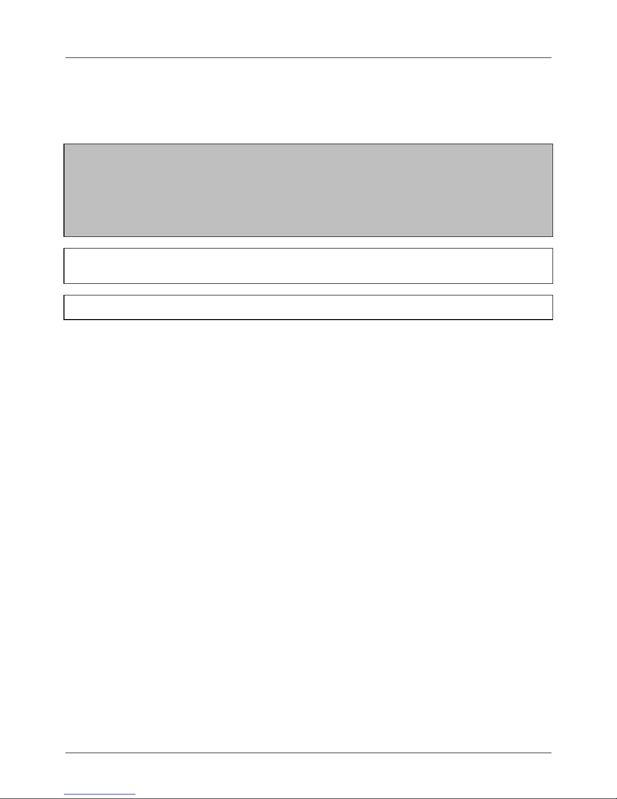
Removing The Covers
Figure 1 - Cover Securing Screw Locations
1 Remove the 8 screws securing the front and side covers.
2 Remove the front cover by lifting it forward and up from the CCU.
3 Remove the side panels by sliding the upwards and lifting them away from the side of the CCU
Panasonic Digital Business System - Installation Manual
March 1997 Issue 5
7
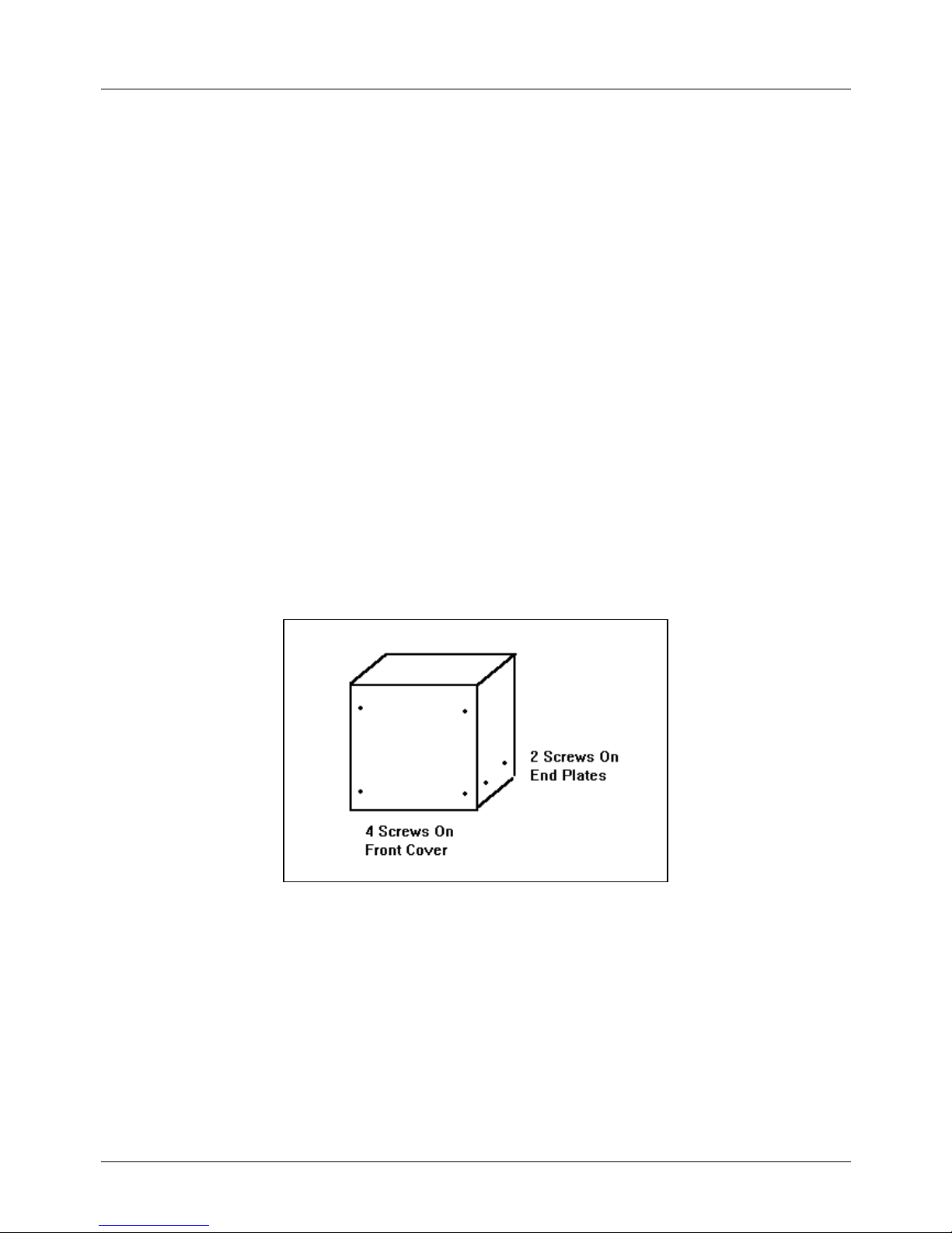
Wall Mounting The CCU
1 Using the dimensions given for the appropriate CCU size in the table below fix four mounting screws into
the wall leaving a 7mm protrusion to accept the mounting plate. Ensure the fixing method is appropriate to
the type of wall.
2 Fix the four mounting plates provided to the rear of the CCU using 2 screws per plate.
3 Lift the CCU and use the holes in the mounting plates to hang it on the screws mounted in the wall.
4 Tighten the screws to secure the CCU.
Figure 2 - Wall Mounting The CCU
Table 1 - Mounting Point Dimensions
A B
DBS 38 335 mm 570 mm
DBS 68 445 mm 570 mm
DBS 90 445 mm 570 mm
Panasonic Digital Business System - Installation Manual
March 1997 Issue 5
8
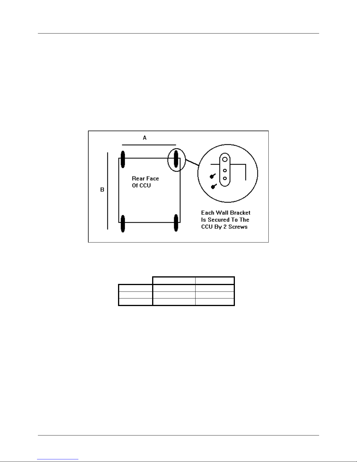
Connection Of The Mains Lead
The DBS must be connected to the mains via a fused spur with a double pole isolation switch provided at the spur
output or close to the equipment.
The wires in the mains lead correspond to the following code:
Wire Colour Meaning / Terminal Possible Alternative Terminal
Markings
Blue Neutral N or coloured black
Brown Live L or coloured red
Green / Yellow Earth E or safety earth symbol
or coloured green
or coloured green and yellow
Table 2 - Wiring Colour Codes
If in doubt consult a qualified electrician.
Figure 3 - Connection Of Mains Lead
Panasonic Digital Business System - Installation Manual
March 1997 Issue 5
9
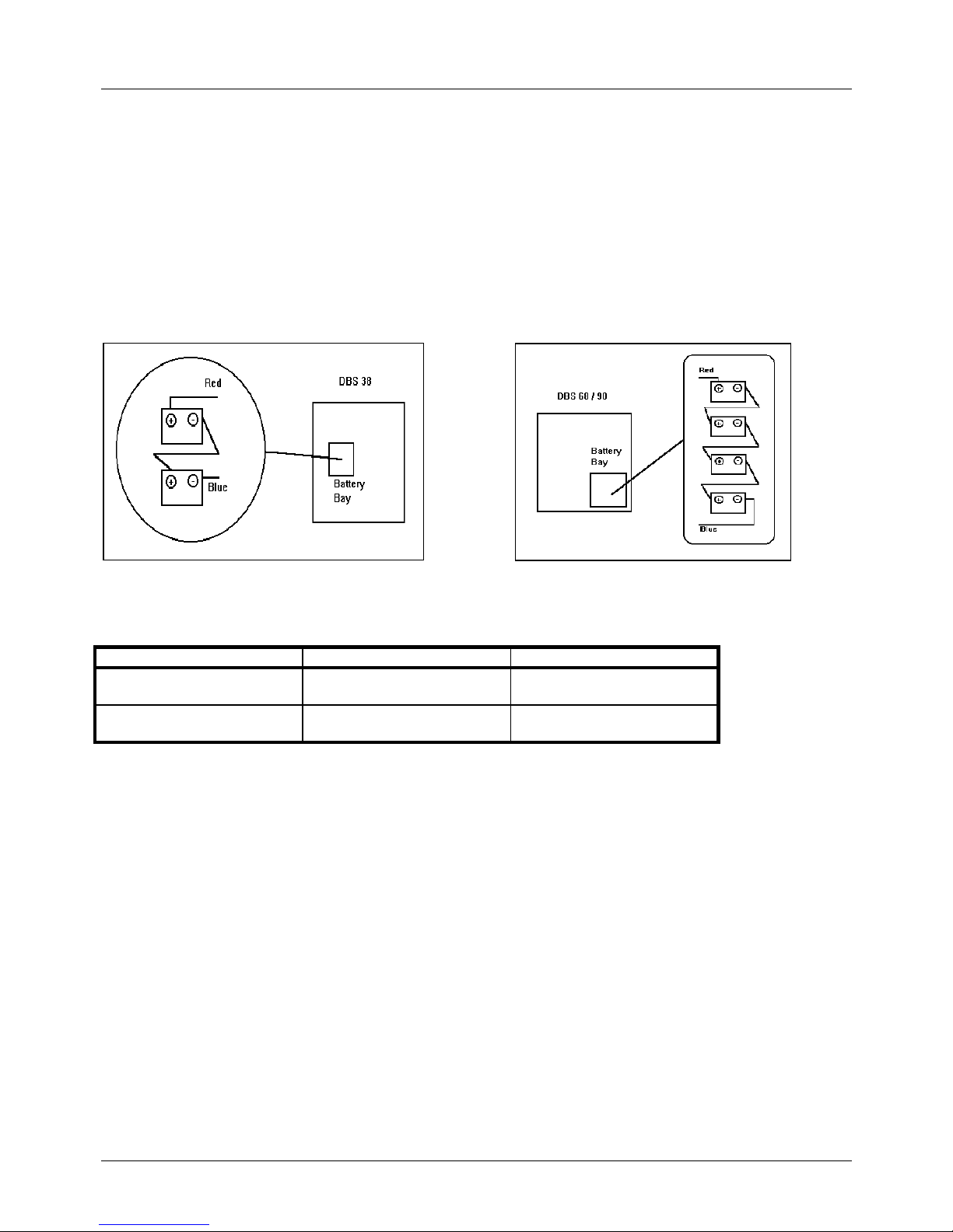
Installing The Built In Backup Batteries
There are two types of internal battery. One type for the DBS 38 and another for the DBS 68 and DBS 90. Use the
set appropriate to the CCU being installed.
1 Link the batteries together as shown below.
2 Connect the red and blue leads to the + and - terminals respectively of the end batteries.
3 Insert the batteries into the bay in the CCU.
Figure 4 - Battery Wiring & Location DBS 38, DBS 68 & DBS 90
Model Number For CCU Specification
VB2450A2UK DBS 38 Sealed lead acid battery
2 x BT2007 (P) 12v 6.5Ah
VB26502UK DBS 68 / 90 Sealed lead acid battery
4 x BT2005 (P) 6v 8.5Ah
Table 3 - Internal Battery Specifications
Note 1: The batteries can maintain system operation for approximately 30 minutes for a DBS 38 or DBS 68 or 15
minutes for DBS 90. The duration of system operation on battery power is dependant upon the traffic
conditions at the time.
Note 2: Panasonic recommend replacement of the backup batteries every three yeas.
Note 3: The parts listed in table 3 are recommended. However any batteries which meet the specification can be
substituted.

Panasonic Digital Business System - Installation Manual
March 1997 Issue 5
10
Installation Of The Modular Cards
The DBS is configured using modular cards to support exchange lines, digital extensions, analogue extensions
and system control functions. These cards are installed in the CCU in designated slots. The numbers of slots and
hence the numbers of cards each CCU can support varies with the CCU used. The table below shows how many
of each card can be installed in each CCU.
Larger DBSs are created by linking a DBS 90 CCU to a second DBS CCU cabinet. the link is via the link cable
cards and cable (VB3691UK). The CCU which contains the CPC card and SCC card is the Master CCU and the
second CCU is the Slave CCU. When CCUs are linked in this way the AUX1 slot in the Master and SCC slot in the
Slave are not used.
Each CCU has one universal slot marked EXT/LINE which is capable of supporting all extension and trunk card
types. In a double CCU system there are two EXT/LINE slots, one in each CCU.
To install a card:
1 Turn off the system power and remove the front cover.
2 Hold the card to be installed with the connection strip facing the backplane of the CCU and the name label
at the top. Check that the card can be installed in the required slot.
3 Locate the guides at the top and bottom of the card into the guide slots in the CCU and gently push the
card into the CCU. When it reaches the connection strip on the backplane a slightly heavier push will
engage the connectors and the card front twill be flush with the front edge of the slot.
4 Rewire system MDF if required.
5 Switch On The System.
Repeat 2 & 3 for each card to be installed.
Panasonic Digital Business System - Installation Manual
March 1997 Issue 5
11
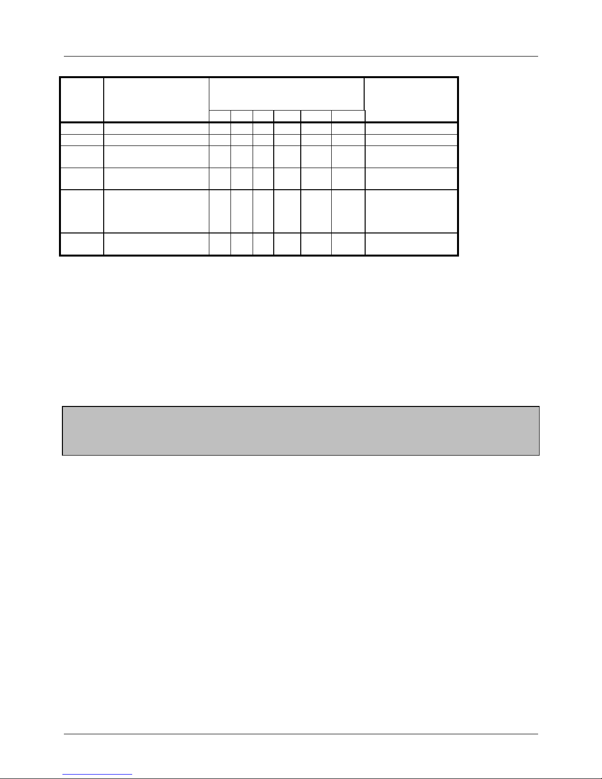
Slot Card
Description
Number Of Slots In CCU
By System Size
Card Model
38 68 90 128 158 180
CPU Central Processor 1 1 1 1 1 1 VB3775
SCC System Control 1 1 1 1 1 1 VB3665A
LINE Line Card
E&M Card
(Note 3)
1 2 3 4 5 6 VB3660
VB3663
EXT Digital Extension Card
Analogue Ext. Card
3 6 8 11 14 16 VB3670
VB3680
EXT /
LINE
Line Card
Extension Card
E&M Card
(Note 3)
ISDN Card
(Note 4)
1 1 1 2 2 2 VB3660
VB3670 / VB3680
VB3663
VB3664
AUX DTMF Receiver
Link Cable
2 2 2 2 2 2 VB3682
VB3691
Table 4 - Relation Between Slots And Modular Cards
Note 1: Never remove the cover of a modular card.
Note 2: To ease installation of multiple cards install then working from the left of the CCU to the right. LINE -DEC-
AEC-SCC-CPC-MFR- Link card.
Note 3: A maximum of 2 E&M cards can be fitted to any CCU. The DBS 38 CCU can take 1, the DBS 68 and 90
CCUs can take 2. Refer to the E&M card installation instructions for full details.
Note 4: A maximum of 1 ISDN card can be fitted to any system regardless of size. It must occupy a universal slot.
See ISDN card installation instructions for full details.
Important
The first extension card fitted to a system in slot EXT1
MUST be a digital extension card
Panasonic Digital Business System - Installation Manual
March 1997 Issue 5
12
Linking Two CCUs
CCUs are linked using the connection cables and cards VB3691. The master CCU must be a DBS 90. One CPU
card and one SCC are installed in the master CCU to provide control for the whole system. When two systems are
linked the SCC slot in the slave and AUX 1 slot in the master are not used.
1 Remove the covers from the CCUs. Install the link cards in the AUX 2 slots at the right hand side of the
CCUs. Ensure the master card is installed in the master CCU and the slave in the slave CCU.
2 Connect the wire provided on the slave card to the 24v pin of the 24v and GND terminal CN24 on the
slave CCU.
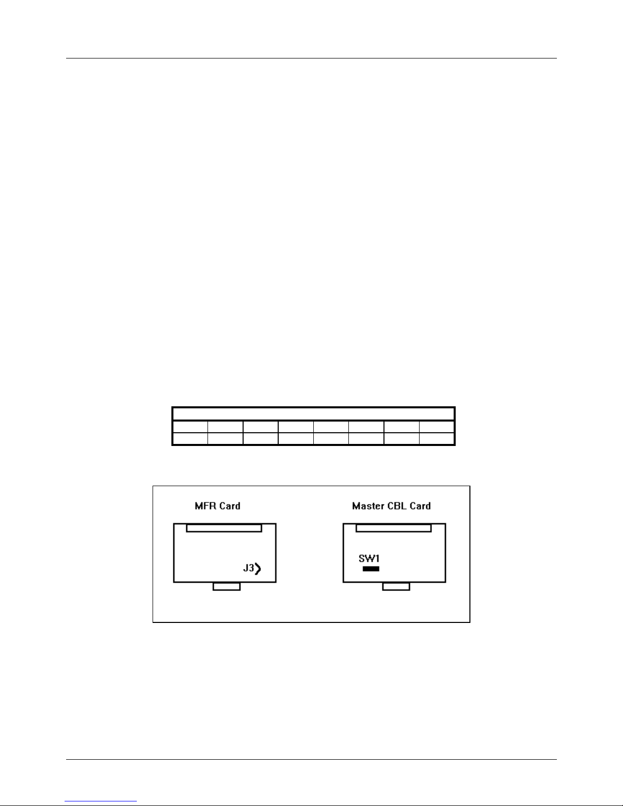
3 If two DTMF Receiver (MFR) cards are fitted to the system cut the jumper wire marked J3 on either of the
MFR cards. Failure to do this will cause the MFR cards to cancel out and DTMF dialling will not be
recognised by the system.
4 The first extension card of the master CCU must be a Digital extension card (DEC). The remaining
extension cards can be any combination of Analogue extension card (AEC) and DEC.
5 Ensure the switch SW1 on the master connection card is set to the factory default shown in table 5 below.
6 Connect the link cable to the cards through the access holes provided in the chassis of the CCUs.
7 Connect the flying leads from the master end of the connection cable to a frame ground on the master
CCU.
8 Allow for the reinstallation of the CCU covers and install the EMI filters as close as possible to the CCUs
at both master and slave ends.
Table 5 - SW1 Factory Presets
Figure 5 - Jumper And Switch Locations
SW1 Switches
1 2 3 4 5 6 7 8
OFF ON OFF ON OFF OFF OFF OFF
Panasonic Digital Business System - Installation Manual
March 1997 Issue 5
13
Connection Of Exchange Lines And Extensions
To comply with EMC Directive 89/336/EEC and it amendments 92./31/EEC and 93/68/EEC, EMI filters must be
installed as per the EMI Filter Installation section later in this manual.
Connection of exchange line and extension wiring to the DBS is made via proprietary DDK connectors supplied
with the CCU. Additional connectors can be obtained as spare part items.
Each DDK can accommodate two exchange or extension connections.
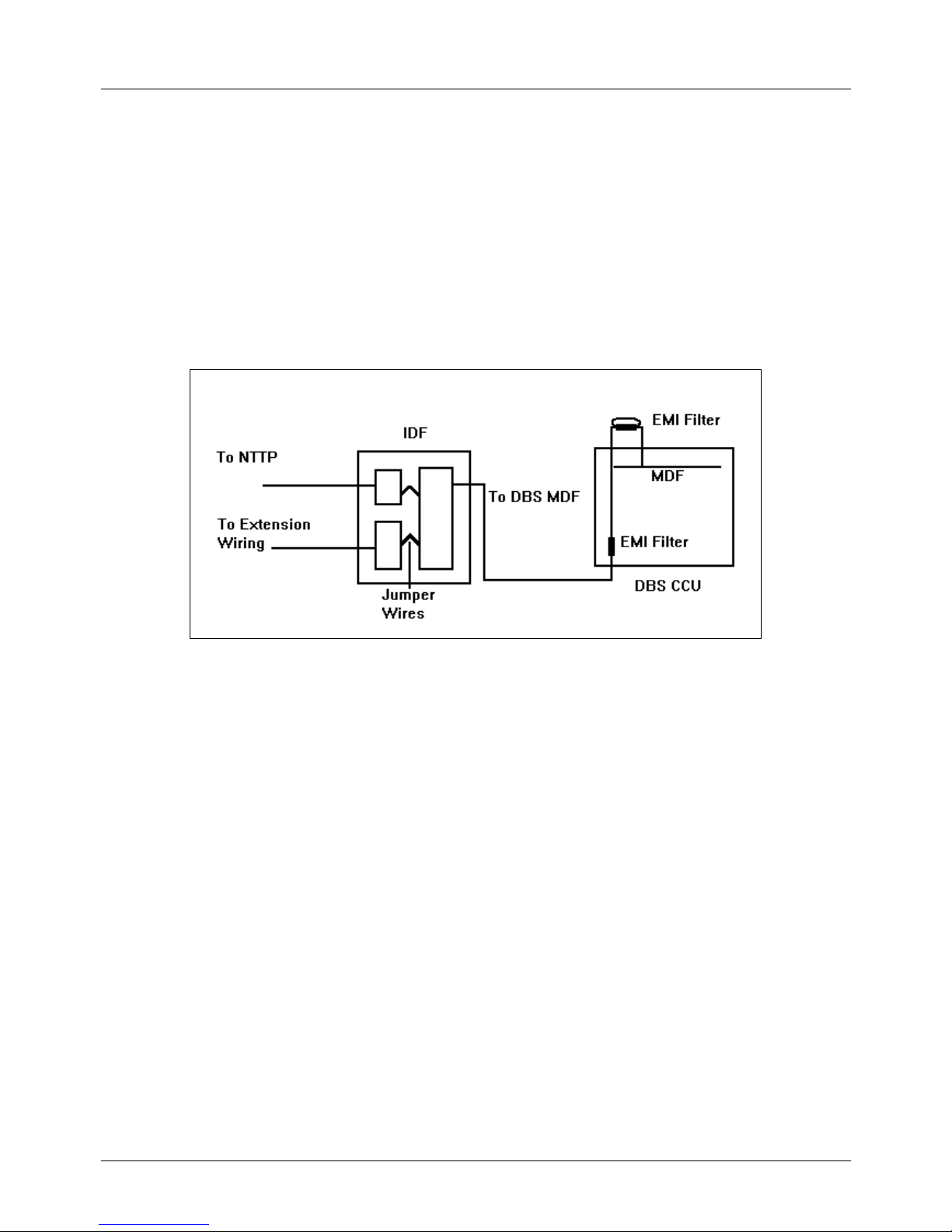
The DBS can be directly wired to the Network Test an Termination Point (NTTP) via DDKs, however it is
recommended that an Intermediate Distribution frame (IDF) is installed and the exchange and extension wiring
jumpered across to the wiring running to the DBS.
Figure 6 - Recommended Connection Schematic
Attaching A DDK Connector
1 Open the DDK.
2 Insert the wires to connected into the four holes on the flap.
3 Ensure the wires do not slip out of the holes and close the DDK using a pair of pliers to press the two parts
firmly together. The blades in the second section of the DDK will cut through the insulation on the wire and
make contact with the conductor.
4 Plug the completed DDK into the appropriate port connection on the Master Distribution Frame (MDF) at
the top of the DBS CCU.
Panasonic Digital Business System - Installation Manual
March 1997 Issue 5
14
Piggy-Back Connections
The DBS can be used a host or subsidiary system. As a subsidiary system piggy-backed from the extension ports
of a host PBX the connection from the host is presented as a series of exchange lines to the DBS. The DBS is
then configured through programming to use those ports as piggy-backed lines and will provide recall signalling to
the host.
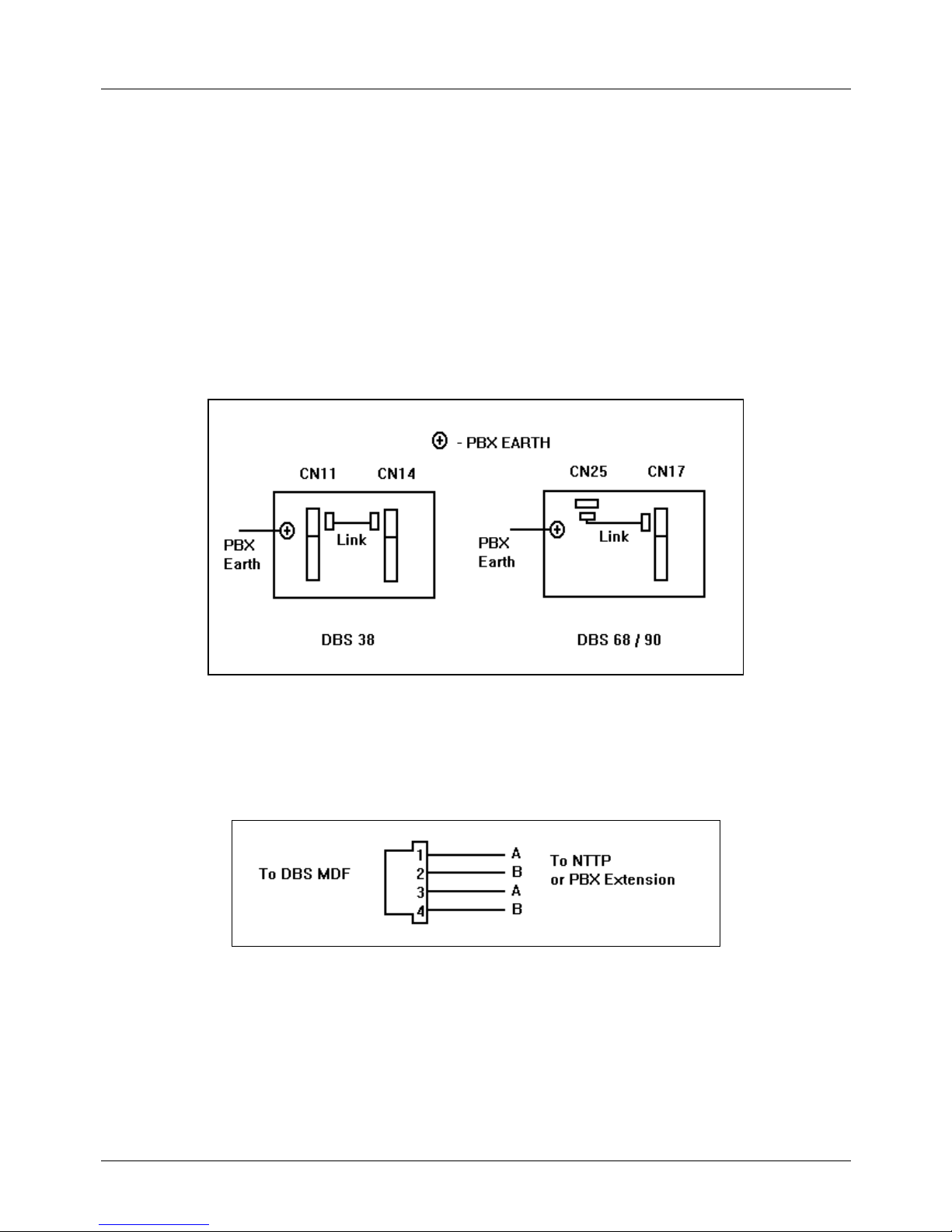
The DBS can be configured to provide earth or timed break recall signalling to the PBX. Timed break will operate
on the wiring from the PBX extensions. Earth recall will require the connection of an earth wire from the PBX earth
point to the PBX EARTH connection point on left hand end of the DBS MDF.
If an earth connection is required to the DBS this must also be carried across to the EXT/LINE slot wiring using a
DDK to DDK jumper wire so that any PBX extensions connected there can also send earth recall. The following
diagram shows the location of the connection points on the DBS CCUs.
Figure 7 - PBX Earth Connection Points
Exchange Line / PBX Extension Wiring
Use each DDK to connect two circuits as shown.
Figure 8 - Exchange Line / PBX Extension Connection
Panasonic Digital Business System - Installation Manual
March 1997 Issue 5
15
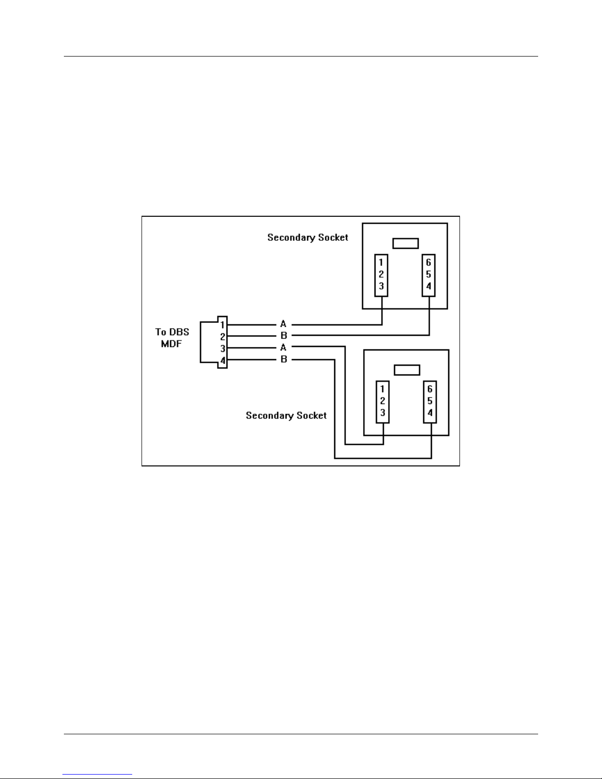
Extension Connection
Extension connections are made via DDK connectors in a similar way to those for the exchange lines. Both Digital
and Analogue extensions connect using two wires. The DSS operator console is wired as a digital extension or
piggy backed with the operator extension. Extension ports 1 and 2 are the ports for operator extensions DSS units
when installed will operate with one or other of these ports as per system programming.
Digital Extension Connection
Digital Extensions are wired to secondary sockets pins 3 and 4.
Figure 9 - Digital Extension Connection
Panasonic Digital Business System - Installation Manual
March 1997 Issue 5
16
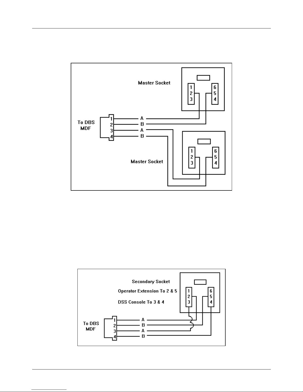
Analogue Extension Connection
Analogue Extensions are wired to master sockets pins 2 and 5.
Figure 10 - Analogue Extension Connection
DSS Console Connection
DSS 1 for the operator extension on port 1 and DSS 1 for the operator extension on port 2 can be wired sharing
the same socket as the extension or wired as an individual digital extension. When the socket is shared use the
link wire supplied with the DSS to connect the operator extension to the DSS unit then connect only the cord from
the DSS unit to the socket.
The second DSS unit for each operator is wired as a digital extension.
DSS consoles can be connected to any vacant digital extension port supported by a digital extension card.
Figure 11 - DSS Console Connection
Panasonic Digital Business System - Installation Manual
March 1997 Issue 5
17
Wall Mounting The Proprietary Extension Telephones
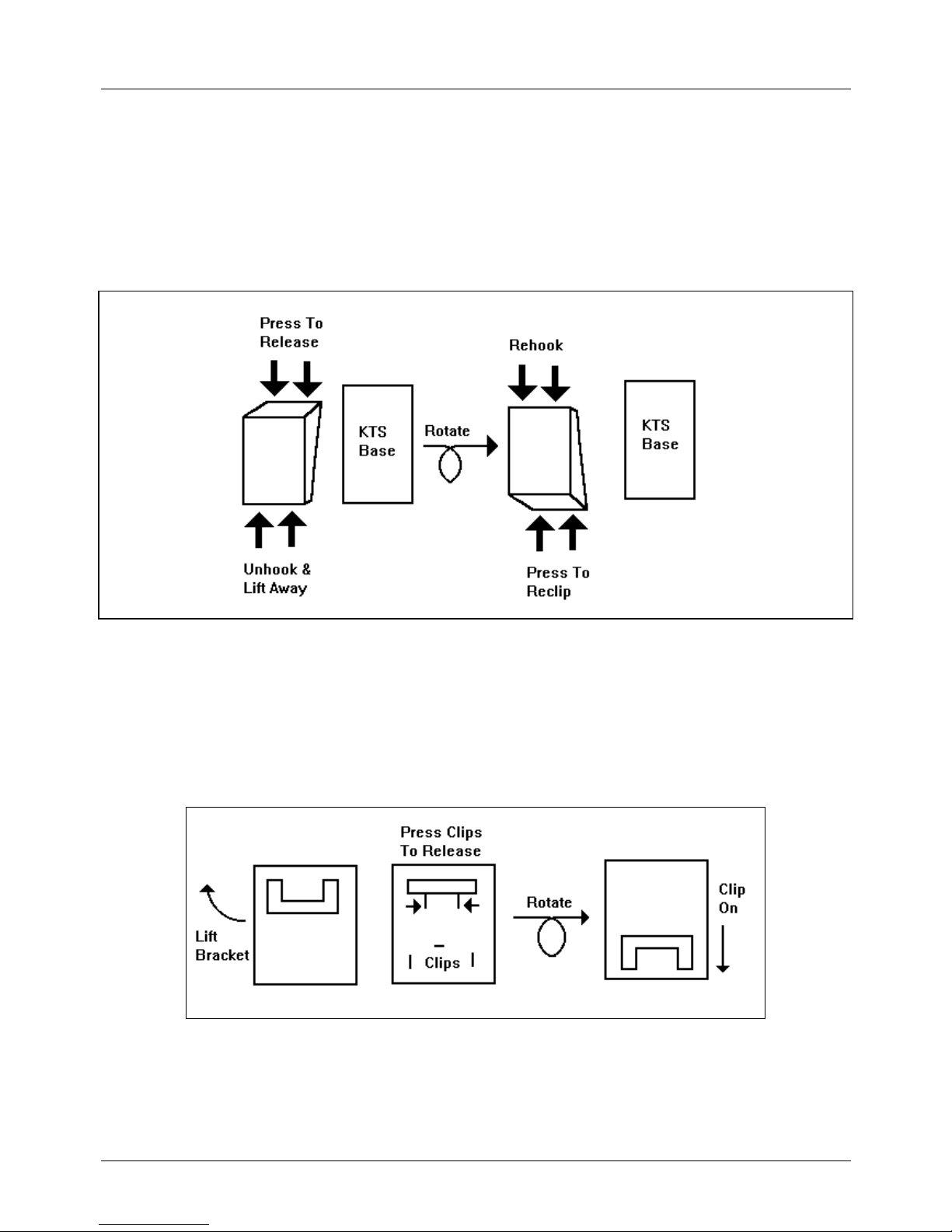
The VB3411, VB3411D, VB3411LDS, VB3611D and VB3611DS
The VB3411, VB3411D, VB3411LDS, VB3611D and VB3611DS handsets have a base moulding which can be
unclipped rotated and reattached to provide wall a wall mounting bracket.
Figure 12 - Removal And Reattachment Of The Built In Wall Bracket
Wall Mounting The VB3011
The VB3011 has a built in wall mounting bracket which is removed and refitted by lifting the bracket and pressing
the two holding clips to release the bracket. Rotate the bracket and re-clip it onto the three clips provided at the
base of the handset. Remove the plastic section to free the screw hole.
Figure 13 - Wall Mounting The VB3011
Panasonic Digital Business System - Installation Manual
March 1997 Issue 5
18
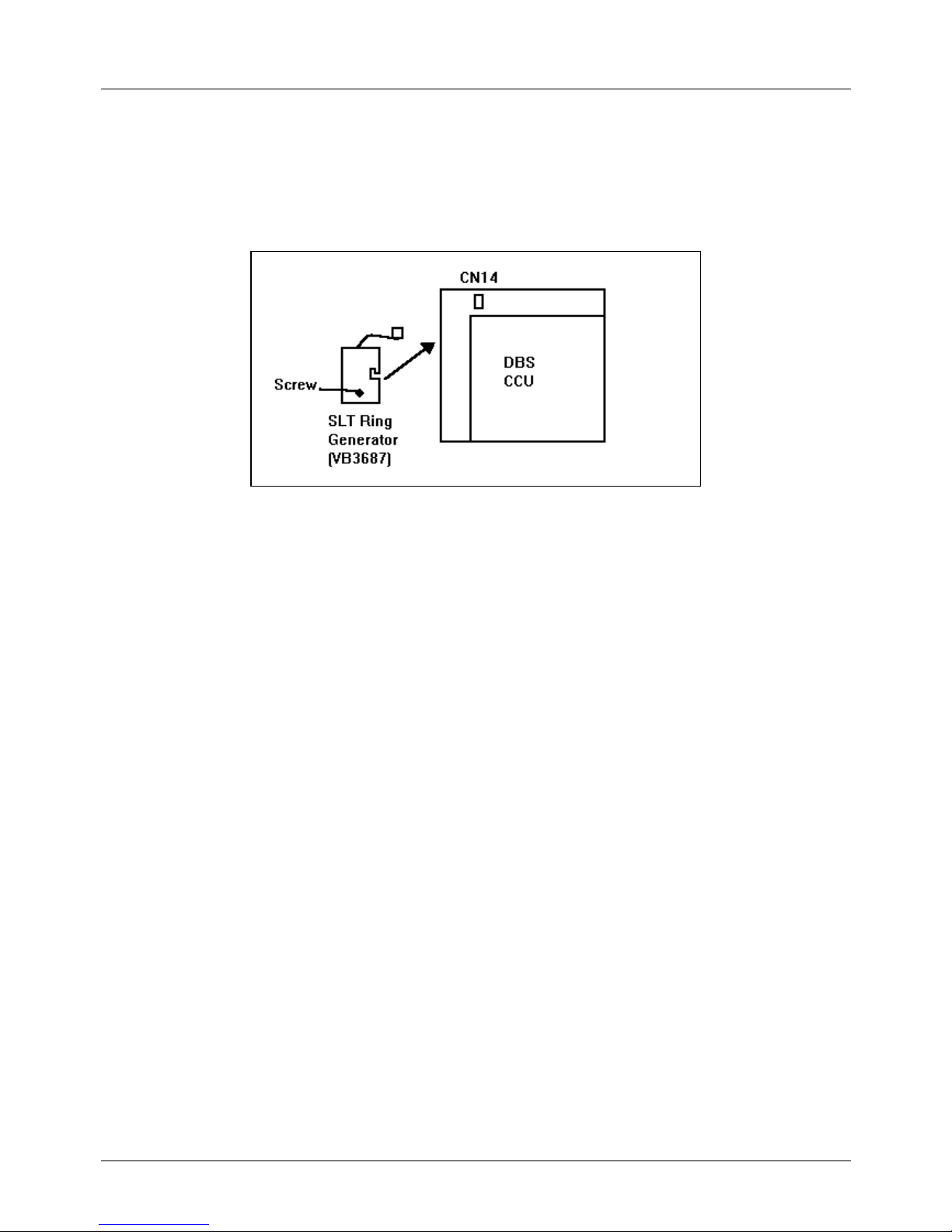
SLT Ring Generator
The SLT Ring Generator is a power supply to provide ringing voltage for analogue extensions. It is sufficiently
powerful to ring 20 analogue extensions at any one time. One Ring Generator is required for every CCU. When
installing a double CCU system one Ring Generator must be fitted to each CCU in which analogue extensions are
connected and required to ring.
Figure 14 - Fitting The SLT Ring Generator
 Loading...