

Page 1
Page 2
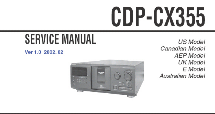
CDP-CX355
SECTION 4
SERVICE MODE
SPECIAL FUNCTION
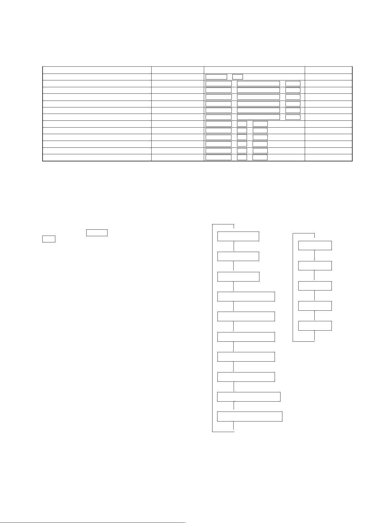
This unit is provided with several service modes.
Details are shown in the following table.
Mode name
ALL ERASE
AGING MODE
LOARDING AGING MODE
T ABLE A GING MODE
DOOR POP UP AGING MODE
TABLE LOTATION MODE
TITLE MEMO SHIFT MODE
MODEL NAME DISPLAY
MICROPR OCESSOR VERSION DISPLA Y
ALL LIT MODE
MECHANISM ADJUSTMENT MODE
SHIPMENT MODE
TITLE MEMO RECORDING CHECK MODE
Note 1
Do not execute unless with a proper reason, otherwise the memory of the title memo recorded by the customer will be erased.
The title memo recording check mode is not required for servicing. Do not execute.
ALL ERASE
This mode is used for clearing information such as the title memo.
Do not execute if information such as the title memo is not to be
erased.
Procedure:
While pressing the CLEAR button with the power OFF, press the
1/u button and turn on the power.
The fluorescent display tube displays “ALL ERASE” and all
memories will be cleared.
AGING MODE
• Mode which repeatedly changes and plays back discs automatically in the unit.
• It will repeat aging as long as no errors occur.
• If an error occurs during aging, it will stop all servos, motors, etc.
instantaneously, display the error number, and stop operations.
However , the stopping conditions dif fer according to whether the
unit is equipped with the “self-protection function during errors”
described later.
The function serves to maintain the state of the unit when errors
occur.
Power supply state
OFF
ON
ON
ON
ON
ON
ON
ON
ON
ON
ON
ON
ON
Button operation
CLEAR + ?/1
GROUP 1 + § OPEN/CLOSE + +100
GROUP 2 + § OPEN/CLOSE + +100
GROUP 3 + § OPEN/CLOSE + +100
GROUP 4 + § OPEN/CLOSE + +100
GROUP 5 + § OPEN/CLOSE + +100
GROUP 7 + § OPEN/CLOSE + +100
GROUP 1 + · + +100
GROUP 2 + · + +100
GROUP 3 + · + +100
GROUP 4 + · + +100
GROUP 5 + · + +100
GROUP 6 + · + +100
Sequence of Aging Mode
$
1. Disc change
$
2. Load in
$
3. TOC read
$
4. Access of last track
$
5. 3 second playback
$
6. Access of first track
Order of Disc Change
Note 1
Used in adjustment
Note 1
Note 1
(1 cycle takes 3 minutes)
$
1. No. 60
$
2. No. 240
$
3. No. 180
$
4. No. 300
$
5. No. 120
$
Remarks
$
7. 3 second playback
$
8. Load out
$
9. FRONT COVER open
$
10. FRONT COVER close
$
21
Page 3
CDP-CX355
Special Aging Mode Functions
The aging mode is provided with the following con venient functions
• Disc setting mode (*1)
• Selection of presence of protection function during error (*2)
• Count function of aging cycle (*3)
*1 Disc setting mode:
5 discs are set before setting the aging mode. This mode makes
the setting of these discs more easy.
*2 Self protection function during errors:
Function which voluntarily corrects errors which occur during
normal operations by retries.
If this function is not provided, all operations will be stopped
without retiring. It is suitable for checking errors with low
reproducibility.
If this function is provided, and errors can be corrected by
retries, aging will be continued without stopping.
*3 Aging cycle count function:
Functions which displays the number of agings carried out on
the Fluorescent indicator tube in numbers. One aging cycle
consists of five discs.
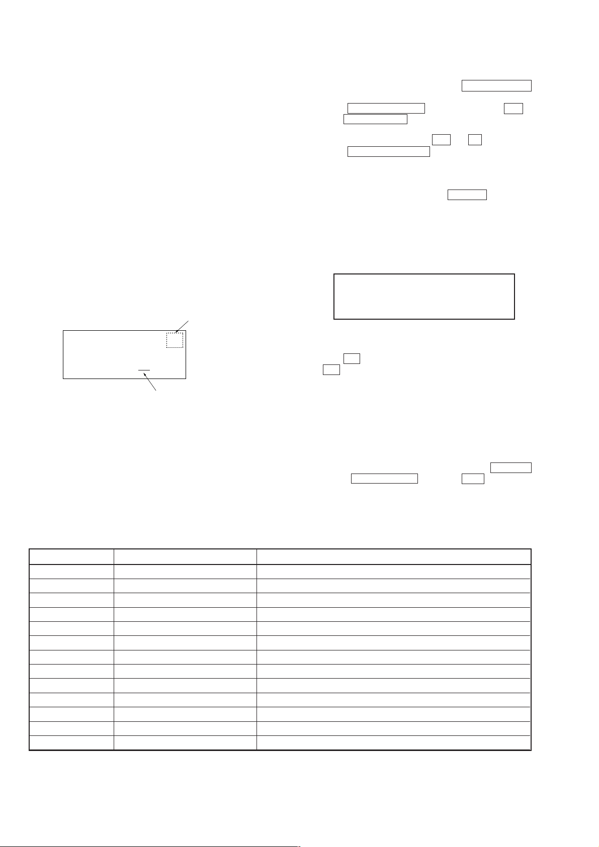
number of disc table
1DISC
DISC
CD1
120
AGED 10
number of agings
Aging Procedure
1. Turn ON the power of the unit. Press the § OPEN/CLOSE
and open the front cover.
2. Change the COMMAND MODE switch (S902) on set to CD1 .
3. Press the AGING START button of the remote commander
for aging mode (J-2501-123-A).
4. When the disc set mode is set, the · and P LEDs blink.
5. Rotate the DISC/CHARACTER dial. The slits (No. 60, 120,
180, 240, 300) for setting the discs will come forward. Insert
the discs into these slits. Do not set the discs in other slits.
6. Set whether the self-protection function during errors is
equipped with the unit. Press the REPEAT button. If
“REPEAT” is displayed on the Fluorescent indicator tube, it
means the function is provided. If “REPEAT” is not displayed,
it means the function is not provided.
Error Display
Disc number
when aging
180
120 E01 #
Disc number
with error
7. Press the · button.
8. The · LED blinks, the aging mode is set, and aging is started.
9. The aging cycle lasts 3 minutes. If errors occur during aging,
the error number will be displayed on the Fluorescent indicator
tube. (Refer to the following table for the details of the errors.)
10. Aging will be repeated as long as no errors occur.
11. After each aging cycle, the number displayed on the Fluorescent
indicator tube will increase.
12. To end aging, disconnect the power cord from the outlet.
Error code
Aging cycle
number
Error code
Err 01
Err 02
Err 03
Err 04
Err 05
Err 06
Err *1
Err *2
Err *3
Err *4
Err *5
Err *6
Err *7
DISC sensor check 1
DISC sensor check 2
Table operation check 1
Table operation check 2
Loading operation check 1
Loading operation check 2
BU related check 1
BU related check 2
BU related check 3
BU related check 4
BU related check 5
BU related check 6
BU related check 7
NOTE: As an alternative to steps 2 and 3, press the GROUP 1
button, §OPEN/CLOSE button, and +100 button at the
same time.
ContentsCode number Name
No disc in the specified slit
Disc in other slits
Table motor current over
No table sensor input
Load in timeover
Load out timeover
Access timeover
High speed search NG
Q data read error
BU operation (from focus search to until signal can be read) timeover
GFS monitor error
Focus cannot be imposed by focus search
Auto focus bias adjustment cannot be performed
The following * numbers mean according to the state of the unit during aging
*2 : From chucking to end of TOC read
*3 : From end of TOC read to end of last track playback
*4 : From end of last track playback to end of first track playback
22
Page 4
CDP-CX355
LOADING AGING MODE
• This mode is used for repeating loading operations continuously.
• Aging will be performed continuously unless an error occurs.
• When an error occurs, the error code will be displayed on the
fluorescent indicator tube.
Procedure:
1. Set a disc in the DISC 1 slit.
2. With the power ON, while pressing the GROUP 2 button and
§ OPEN/CLOSE button, press the +100 button.
3. When the mode is set, both the · and P indicators will
start to blink.
4. When the · button is pressed, only the · indicator will
blink and aging starts.
5. To end the mode, press the 1/u button or disconnect the
power cord from the outlet.
The error codes displayed during operations and when errors occur
are the same as the “AGING MODE” described earlier.
TABLE AGING MODE
• This mode is used for rotating the table randomly.
• Aging will be performed continuously unless an error occurs.
• When an error occurs, the error code will be displayed on the
fluorescent indicator tube.
Procedure:
1. Set discs in slits 1, 2, 99, 100, and 200.
2. With the power ON, while pressing the GROUP 3 button and
§ OPEN/CLOSE button, press the +100 button.
3. When the mode is set, both the · and P indicators will
start to blink.
4. When the · button is pressed, only the · indicator will
blink and aging starts.
5. To end the mode, press the 1/u button or disconnect the
power cord from the outlet.
During aging, operations will be carried out sequentially in the order
of No. 1, No. 2, No. 100, No. 99, and No. 200 slits.
The error codes displayed during operations and when errors occur
are the same as the “AGING MODE” described earlier.
TABLE ROTATION MODE
• This mode is used for electrical adjustments. Refer to the section
on Electrical Adjustments.
TITLE MEMO SHIFT MODE
• This mode is used for writing title memo information recorded in
this unit in a different unit.
Use it for transferring disc memo contents written by the customer to the new units when replacing the unit, etc.
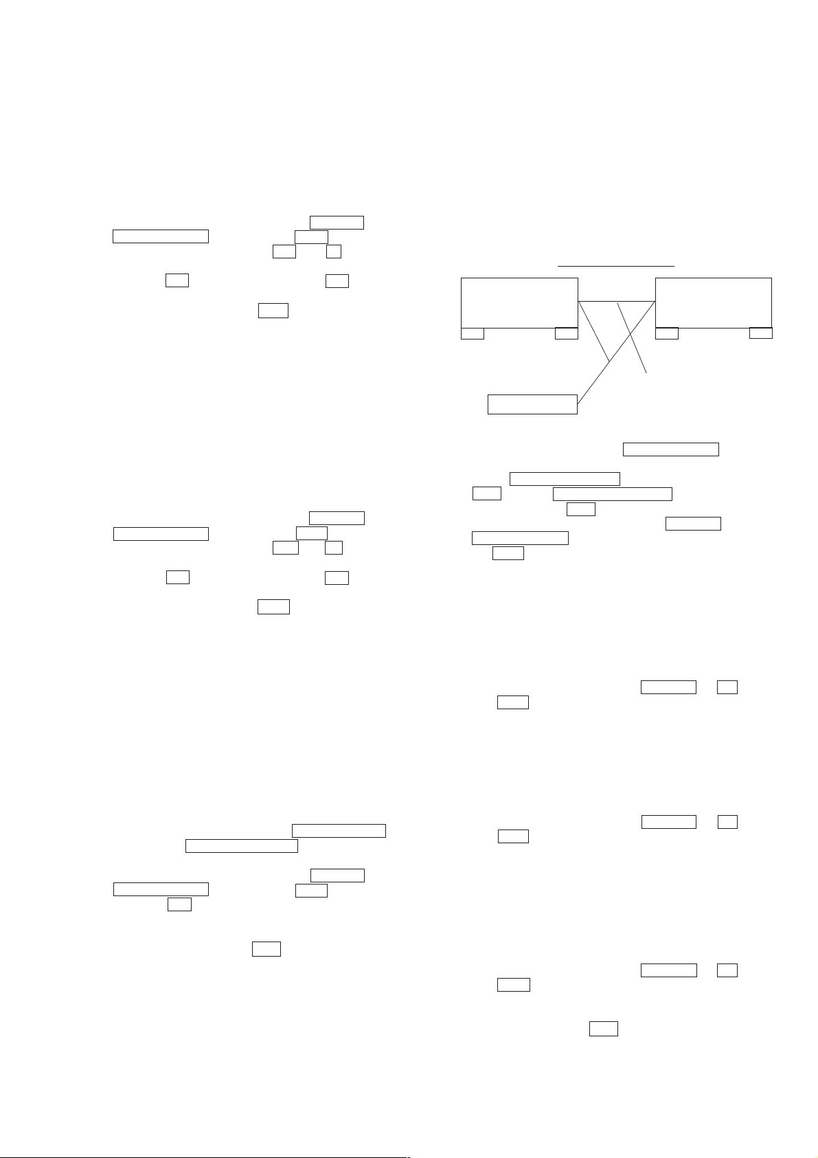
Connection:
Flow of data
$
This unit
(Copy source)
COMMAND MODE: CD3
CONTROL A1
II
$
$
CONTROL A1 II connection cord provided
Another unit
$
(Copy destination)
COMMAND MODE: CD1
Procedure:
1. Connect two units using the CONTROL A1 II connection
cord shown in the figure.
2. Set the COMMAND MODE switch of the copy source unit to
CD3 and the COMMAND MODE switch of the copy
destination unit to CD1 .
3. With the power on, while pressing the GROUP 7 button and
§ OPEN/CLOSE button of the copy destination unit, press
the +100 button.
4. When the data has been transferred, the fluorescent indicator
tube displays “complete” for about 1 second.
MODEL NAME DISPLAY
• Model names can be displayed on the fluorescent indicator tube
for checking the microprocessor model setting, etc.
Procedure:
With the power ON, while pressing the GR OUP 1 and · buttons,
press the +100 button.
The model name is displayed on the fluorescent indicator tube.
DOOR POP UP AGING MODE
• This mode is used for performing aging of the CD pop up part
and door open/close.
It is used for checking if operations are performed normally.
Method:
1. T o select a slot to be aged, press the § OPEN/CLOSE b utton
and rotate the DISC/CHARACTER knob with the front door
opened to select a number.
2. With the power ON, while pressing the GROUP 4 button and
§ OPEN/CLOSE button, press the +100 button.
3. When the · button is pressed, aging starts, and door open/
close and up/down operations of the pop up part are performed
continuously.
4. To end the mode, press the 1/u button.
If DISC is not selected at step 1, aging will be performed at the 192
slot.
The number of times aging is performed will be displayed on the
fluorescent indicator tube during operations.
MICROPROCESSOR VERSION DISPLAY
• The microprocessor version can be displayed on the fluorescent
indicator tube.
Procedure:
With the power ON, while pressing the GR OUP 2 and · buttons,
press the +100 button.
The microprocessor version is displayed on the fluorescent indicator
tube.
ALL LIT MODE
• This mode is used for lighting the whole fluorescent indicator
tubes and LEDs.
Procedure:
With the power ON, while pressing the GR OUP 3 and · buttons,
press the +100 button.
Both the fluorescent indicator tubes and LEDs will light up
completely.
To end this mode, press the 1/u mode.
23
Page 5

CDP-CX355
MECHANISM ADJUSTMENT MODE
• This mode is used for mechanism adjustments. Refer to the section on Mechanism Adjustments.
SHIPMENT MODE
• This mode is used for setting the unit to the shipment state.
Do not execute it without a proper reason as it erases the memory
of the title memo recorded by the customer.
Procedure:
Set the COMMAND MODE switch to CD1 and the TIMER
switch to OFF . Next, with the power ON, while pressing the GR OUP
5 button and · button, press the +100 b utton. If the switch state
is normal, the model name will be displayed on the fluorescent
indicator tube and the unit will set into the shipment mode.
If the various switches are not set to their designated positions, error
codes will be displayed on the fluorescent indicator tube.
TITLE MEMO RECORDING CHECK MODE
This mode is not required for servicing. Do not execute without a
proper reason.
If executed, the memory of the title memo recorded by the customer
will be erased.
24
Page 6
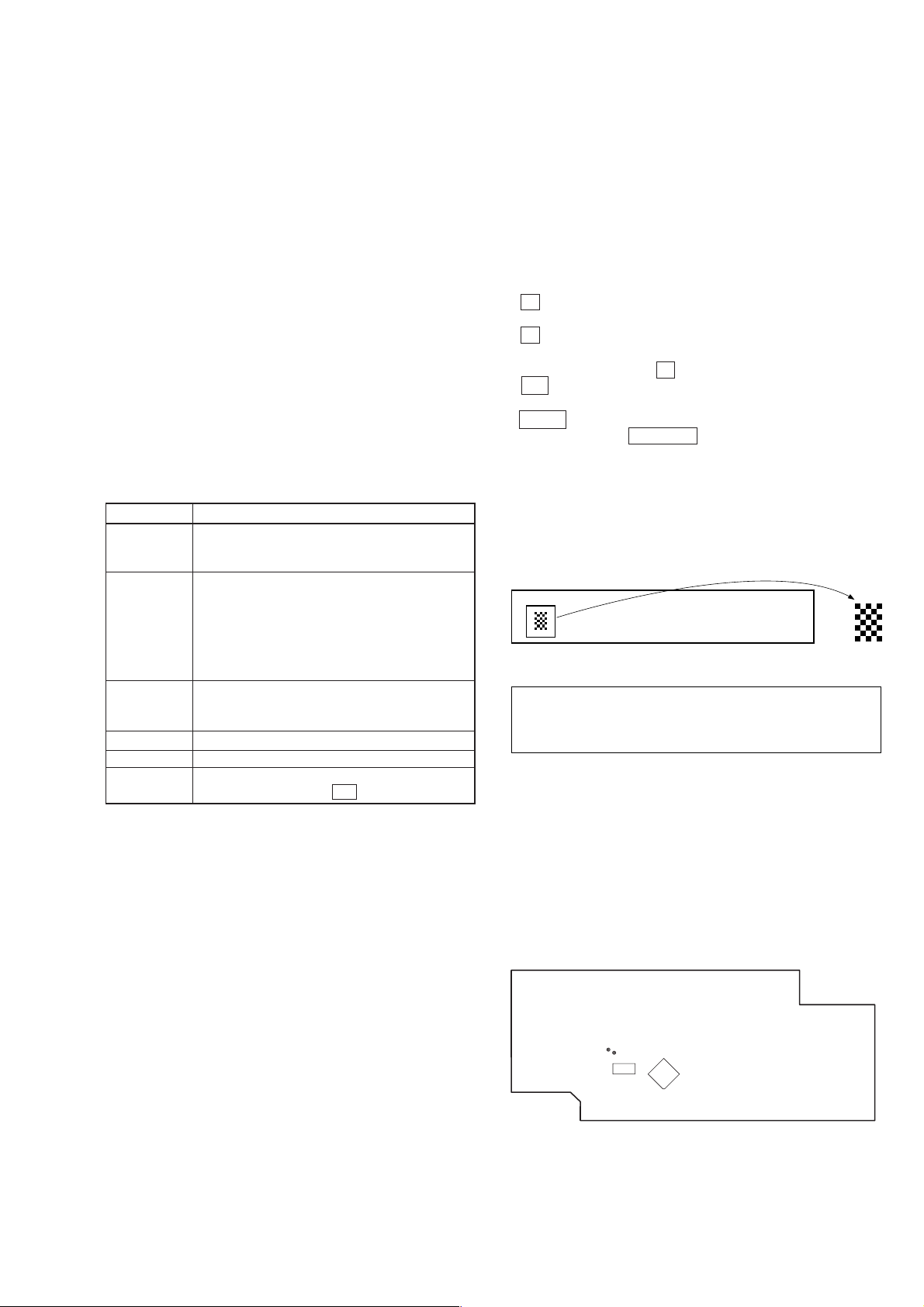
SECTION 5
A B C D E F G
Magnified
TP (AFADJ)
TP (ADJ)
IC504
IC501
TEST MODE
CDP-CX355
5-1. ADJ Mode
1. Turn ON the power of the unit, set disc to disc table, and perform
chucking.
2. Disconnect the power supply plug from the outlet.
3. To set ADJ mode, connect the test point (ADJ) of the MAIN
board to Ground, and connect the power supply plug to the
outlet.
In this mode, table rotation and loading operations are not performed
because it is taken that the disc has already been chucked.
Note:The same operations are also performed in the following when
the test point (ADJ) is connected to Ground after turning on
the power.
• Direct search (movement of sledding motor) is not performed dur-
ing accessing
• Ignored even when GFS becomes L
• Ignored even when the Q data cannot be read
• Focus gain does not decrease
ADJ Mode Special Functions Table
(The buttons shown with ( ) function by using the supplied remote commander only)
Button
CONTINUE
SHUFFLE
PROGRAM
GROUP 3 (3)
GROUP 8 (8)
CHECK
Servo average display
Displays VC, FE, RF, TE and traverse in hexadecimal
numbers
Focus bias display
Each time this is pressed, the focus bias is switched
between (1) and (2)
(1)
Bias actually set Optimum bias Minimum jitter
(2)
U:Upper aliasing bias L:Lower aliasing bias
Auto gain display
Displays focus, tracking, sledding in hexadecimal
numbers
Turns off the tracking and sledding servo
Turns on the tracking and sledding servo
S-curve observation mode.
(Exits this mode when the 1/u button is pressed.)
Function
5-2. Key and Display Check Mode
To set this mode, connect the test point (AFADJ) on the MAIN
board to Ground, and connect the power supply plug to the outlet.
Note: When this mode is executed, all title memos recorded will be
erased.
• When this button is pressed, “line # No. #” will be displayed.
However, these will not be displayed for the following special
buttons. However, these will not be displayed for the following
special buttons.
p (stop) button: FL segment check
(Refer to FL Tube Check Patterns)
P (pause) button: FL grid check
(Refer to FL Tube Check Patterns)
The P LED also light up simultaneously.
· (play) button: All FL segment and grid will light up.
All LEDs also light up simultaneously.
TIMER switch: When the switch position is PLAY , the
STANDBY LED light up. It goes off when
set to OFF.
Each time this button is pressed, the value of the “Got ## keys”
increases. Buttons pressed once will not be counted when pressed
again.
FL Tube Check Patterns
Segment check
Grid check
• When the jog dial is rotated to the right, the GROUP LEDs light
up in the order of 1n2..8nHIT LISTnEASY PLAYnMEGA
CONTROLn1.
• When the jog dial is rotated to the left, the GROUP LEDs light up
in the order of 8n 7..1n MEGA CONTROLn EASY
PLAYnHIT LISTn8.
• Abbreviation
FL: Fluorescent Indicator Tube
[ MAIN BOARD ] – Cnductor Side –
25
Page 7
CDP-CX355
SECTION 6
ADJUSTMENTS
6-1. Mechanical Adjustments
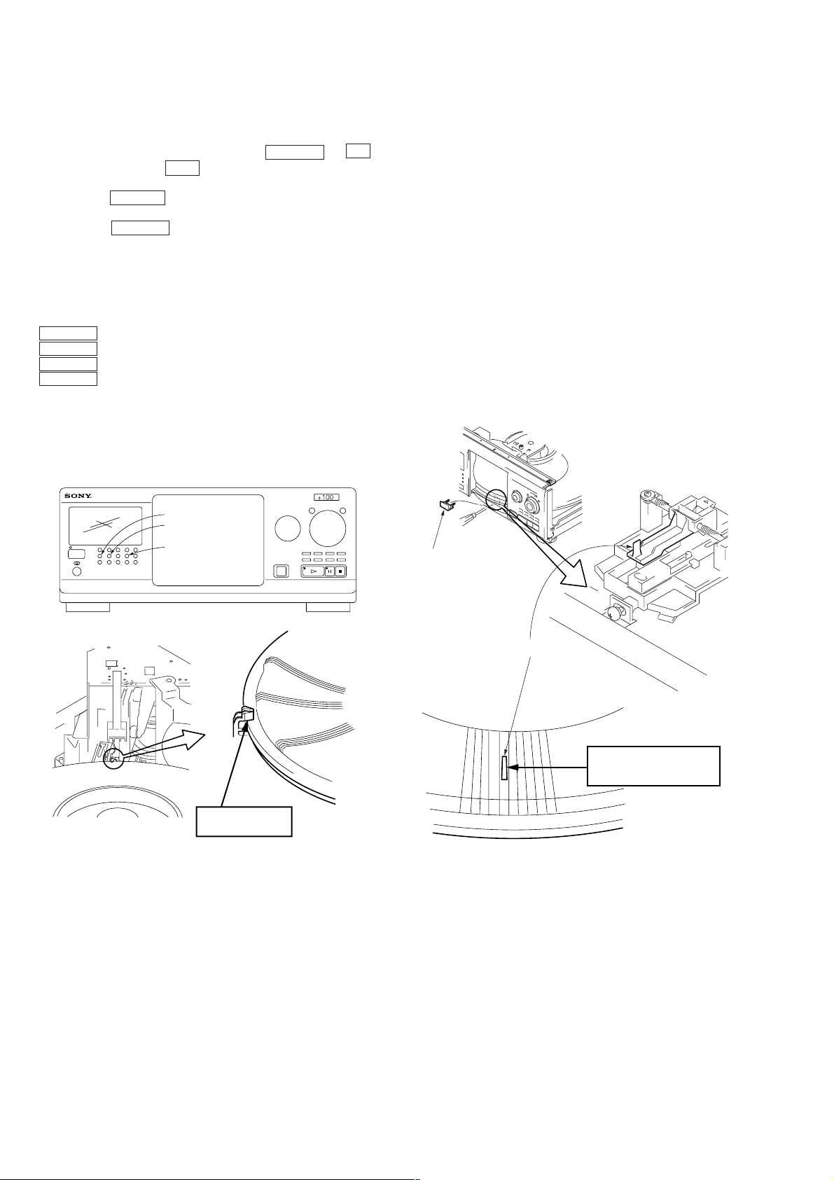
Pop Up Mechanism Adjustment
1. With the power ON, while pressing the GROUP 4 and ·
buttons, press the +100 button to enter the mechanism
adjustment mode.
2. Press the GROUP 1 b utton to operate the loading mechanism,
and continue pressing until the disc table locks. (Fig-1)
3. Press the GROUP 2 button to raise the pop up part.
4. Remove the cov er (chassis), loosen the adjusting screw, move
the screwdriver left and right until the le ver (POP UP) does not
touch the slit wall, and secure the screw. (Fig-2)
The following buttons have special functions in this mode.
GROUP 1 button: Loading mechanism IN operation
GROUP 5 button: Loading mechanism OUT operation
GROUP 2 button: Pop up part UP operation
GROUP 6 button: Pop up part DOWN operation
GROUP1
GROUP2
GROUP4
At this position,this
part will be locked.
Cover (chassis)
Lever (pop up)
FIg-1 FIg-2
Fix to the center so that the
lever (POP UP) does not
touch the slit.
26
Page 8
GROUP1
GROUP4
PAUSE button
PLAY button
Fixed screws
Swing
Holder (table sensor)
Table assembly
At this position,this
part will be locked.
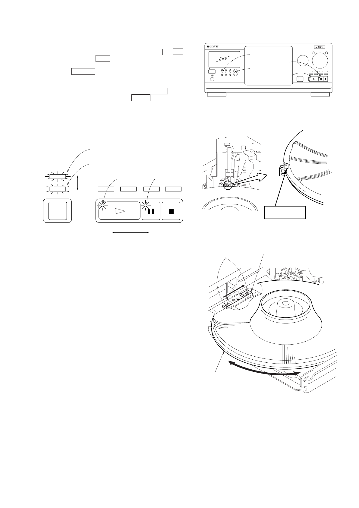
Sensor Adjustment
1. With the power ON, while pressing the GROUP 4 and ·
buttons, press the +100 button to enter the mechanism
adjustment mode.
2. Press the GROUP 1 button to operate the loading mechanism,
and continue pressing until the disc table locks. (Fig-3)
3. Loosen the fixing screw, move the holder (TABLE SENSOR)
slightly, and when the LED (green) of the PLAY button
switches to the LED (orange) of the PAUSE button (or vice
versa), secure the holder (TABLE SENSOR). (Fig-4)
4. Moving the disc table right and left with a hand after the screw
is fixed, the table will move by the play of a disc table. If the
LEDs light up alternately, the adjustment will be performed
correctly. (Fig-4)
Linked with P indicator
CDP-CX355
Linked with · indicator
PLAY indicator
PAUSE indicator
FIg-3
FIg-4
27
Page 9
CDP-CX355
s
V
)
6-2. Electrical Adjustment
Note:
1. CD Block is basically designed to operate without adjustment.
Therefore, check each item in order given.
2. Use YEDS-18 disc (3-702-101-01) unless otherwise indicated.
3. Use an oscilloscope with more than 10MΩ impedance.
4. Clean the object lens by an applicator with neutral detergent
when the signal level is low than specified value with the
following checks.
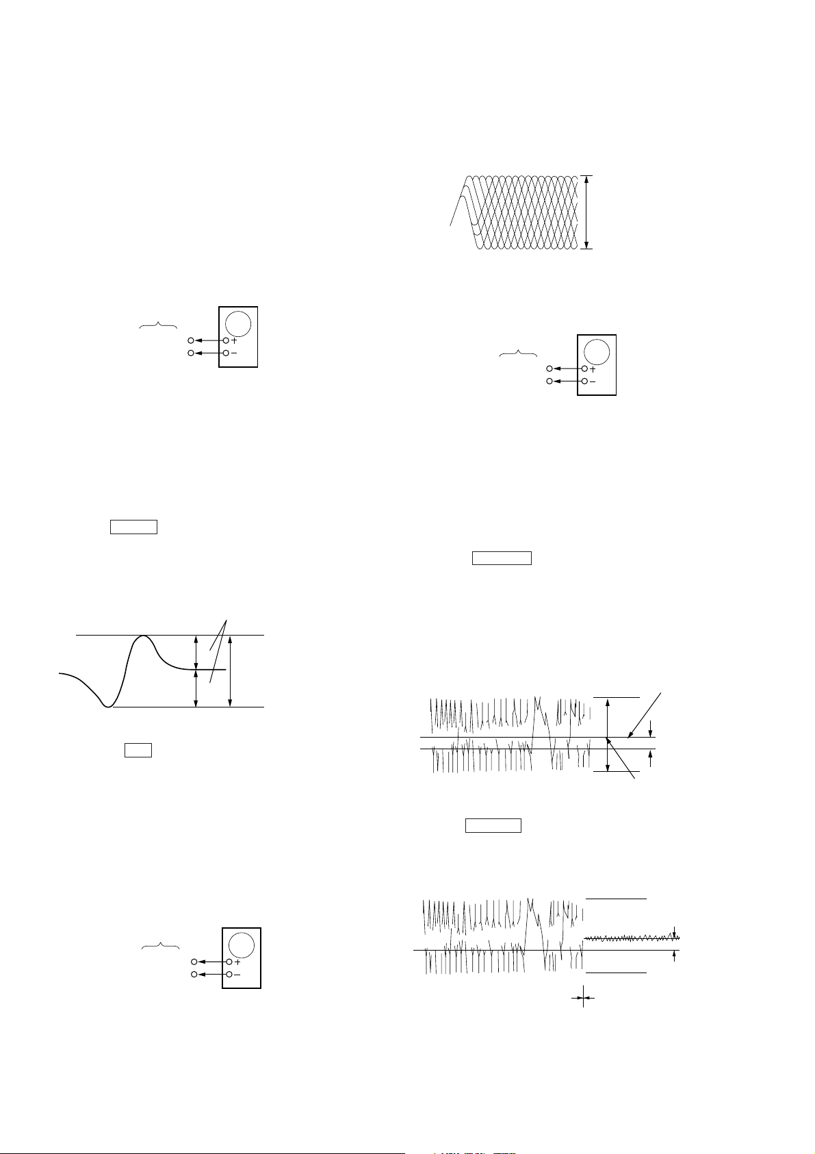
S-Curve Check
oscilloscope
BD board
TP (FE1)
TP (VC)
Procedure :
1. Chuck the disc (YEDS-18) beforehand, and disconnect the
power cord from the outlet.
2. Connect oscilloscope to test point TP (FE1) on BD board.
3. Connect test point TP (ADJ) on MAIN board to ground with
lead wire.
4. The ADJ mode is set when the power cord is inserted into the
outlet and power is supplied.
5. The fifth track is played automatically.
6. Press the CHECK button.
7. Check the oscilloscope waveform (S-curve) is symmetrical
between A and B. And confirm peak to peak level within 3±1
Vp-p.
S-curve waveform
symmetry
A
B
Within 3
VOLT/DIV : 1V
TIME/DIV : 400
±
1 Vp-p
µ
Note: A clear RF signal waveform means that the shape “◊” can be
clearly distinguished at the center of the waveform.
RF signal waveform
VOLT/DIV : 500m
TIME/DIV : 1 µs
level : 1.2 Vp-p
+0.25
–0.20
Adjustment Location: BD board (See page 30)
E-F Balance Check
oscilloscope
BD board
TP (TE1)
TP (VC)
Procedure :
1. Chuck the disc (YEDS-18) beforehand, and disconnect the
power cord from the outlet.
2. Connect oscilloscpe to test point TP (TE1) on BD board.
3. Connect test point TP (ADJ) on MAIN board to ground with
lead wire.
4. The ADJ mode is set when the power cord is inserted into the
outlet and power is supplied.
5. The fifth track is played automatically.
6. Press the GROUP 3 button. (The tracking servo and the
sledding servo are turned OFF.) “ TRK Off ” is displayed.
7. Check the level B of the oscilliscope's waveform and the A
(DC voltage) of the center of the Traverse waveform.
Confirm the following :
A/B x 100 = less than ± 22%
Traverse waveform
Center of the waveform
8. Pressing the 1/u button stops the output of the waveform (s
curve).
9. After check, remove the lead wire connected in step 3.
Note : • Try to measure sev eral times to make sure than the ratio of
A : B or B : A is more than 10 : 7.
• Take sweep time as long as possible and light up the
brightness to obtain best waveform.
Adjustment Location: BD board (See page 30)
RF Level Check
oscilloscope
BD board
TP (RFAC)
TP (VC)
Procedure :
1. Connect oscilloscope to test point TP (RFAC) on BD board.
2. Turn Power switch on.
3. Put disc (YEDS-18) in to play the number five track.
4. Confirm that oscilloscope waveform is clear and check RF
signal level is correct or not.
B
0V
level : 1.3 ± 0.6 mVp-p
A (DC voltage)
8. Press the GROUP 8 b utton. (The tracking servo and sledding
servo are turned ON.) “ TRK On ” is displayed. Confirm the C
(DC voltage) is almost equal to the A (DC voltage) is step 7.
Traverse waveform
C (DC
0V
Tracking servo
Sledding servo
OFF
Tracking servo
Sledding servo
ON
voltage
9. After check, disconnect the lead wire of TP (ADJ) connected
in step 3.
Adjustment Location: MAIN board (See page 30)
28
Page 10
CDP-CX355
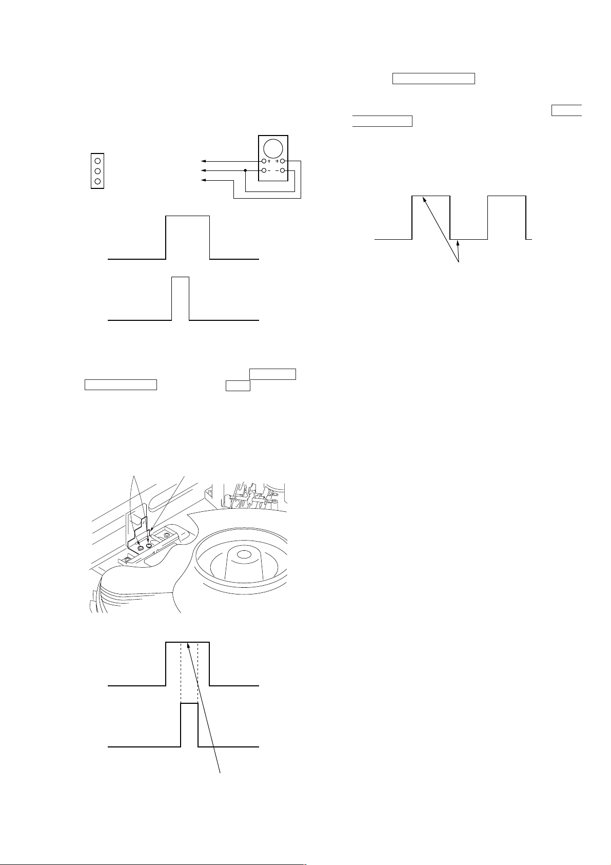
Disc Sensor Adjustment
Be sure to perform this adjustment after sensor adjustment in
MECHANICAL ADJUSTMENT .
Connection:
MAIN board
CN506
D.S
GND
T.P
D.S: Pin
GND: Pin
T.P: Pin
1
2
3
oscilloscope
CH1 CH2
Waveform:
D.S
P.T
1. Connect the oscilloscope to Pins 1, 2, and 3 of CN506 of
the MAIN board.
2. Check that no discs are loaded in the unit.
3. With the power ON, while pressing the GROUP 5 and
§ OPEN/CLOSE buttons, press the +100 button. The disc
table starts to rotate in the clockwise direction.
4. Loosen the fixing screw , move the mounting board (SENSOR),
and secure the mounting board (SENSOR) at the point the H
portion of the P.T waveform comes the center of the H portion
of the D.S waveform.
5. Rotate the DISC/CHARACTER knob in the counterclockwise
direction and the disc table starts to rotate in the same direction.
Check that the waveform at this time is the same as that in step
4. If larger by a considerable extent, rotate the DISC/
CHARACTER knob in the clockwise direction and the disc
table starts to rotate in the same direction. Repeat from step 4.
6. Rotate R V501 of the MAIN board and adjust so that the H and
L portions of the D.S waveform become the same.
D.S
Adjust so that these widths
become the same.
Adjustment Location: MAIN board (See page 30)
Fixing screw Mounting board (SENSOR)
D.S
P.T
Should be at the center
29
Page 11
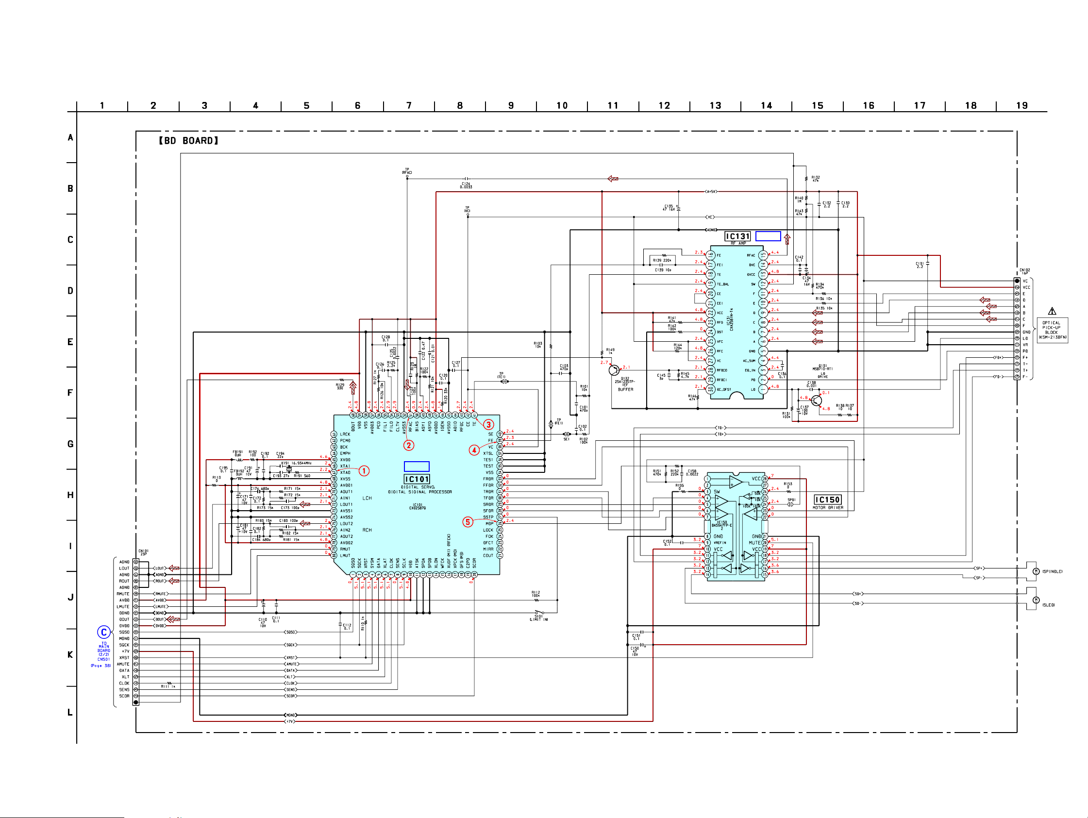
7-3. Schematic Diagram – BD Section –
• See page 31 for Waveforms.
• See page 47, 48 for IC Block Diagrams.
• See page 50 for IC Pin Function.
CDP-CX355
IC B/D
RFSW
IC B/D
3535
Page 12
CDP-CX355
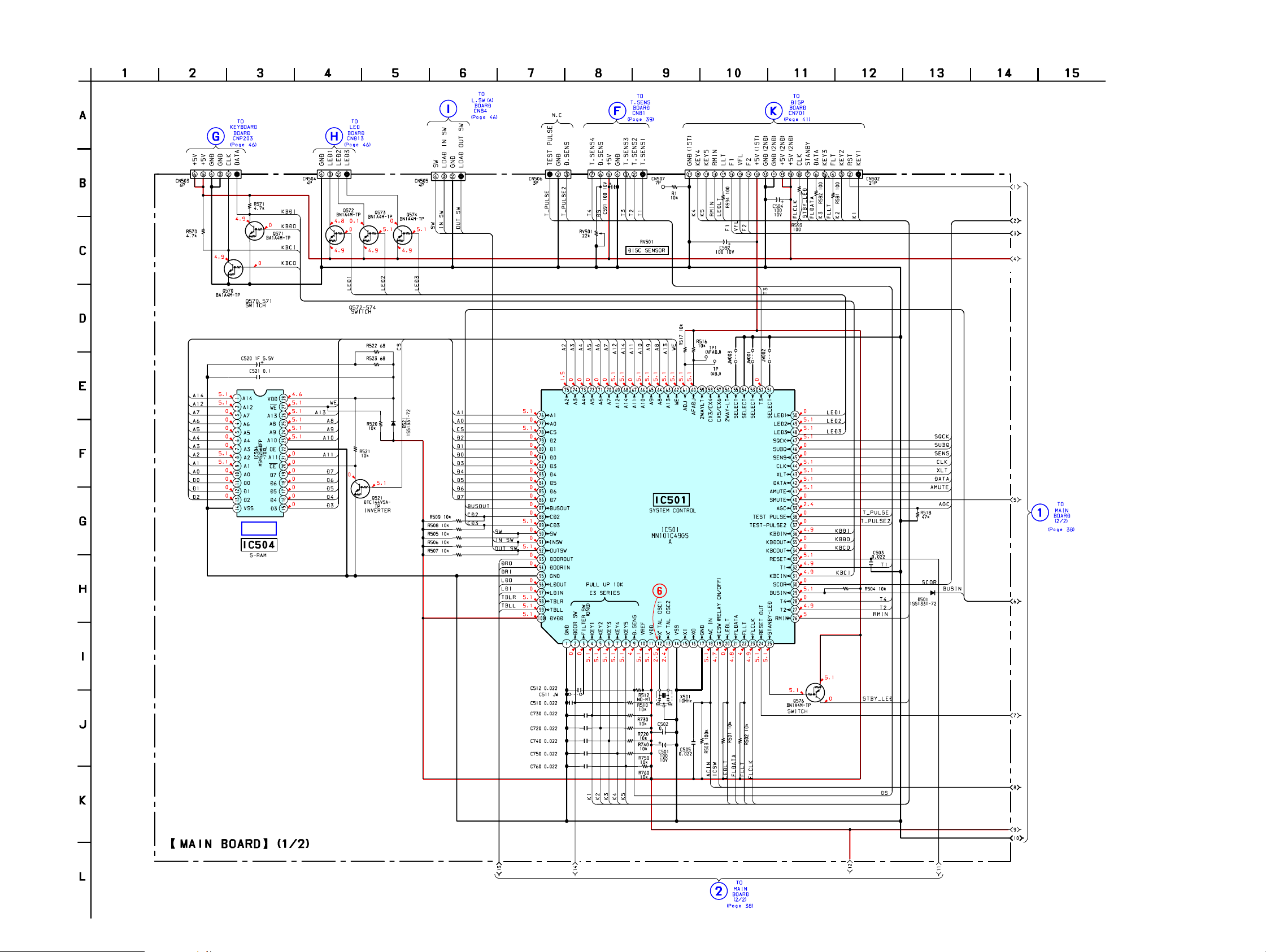
7-5. Schematic Diagram – MAIN Section (1/2) –
• See page 31 for Waveform. • See page 48 for IC Block Diagrams. • See page 52 for IC Pin Function.
IC B/D
3737
Page 13
CDP-CX355
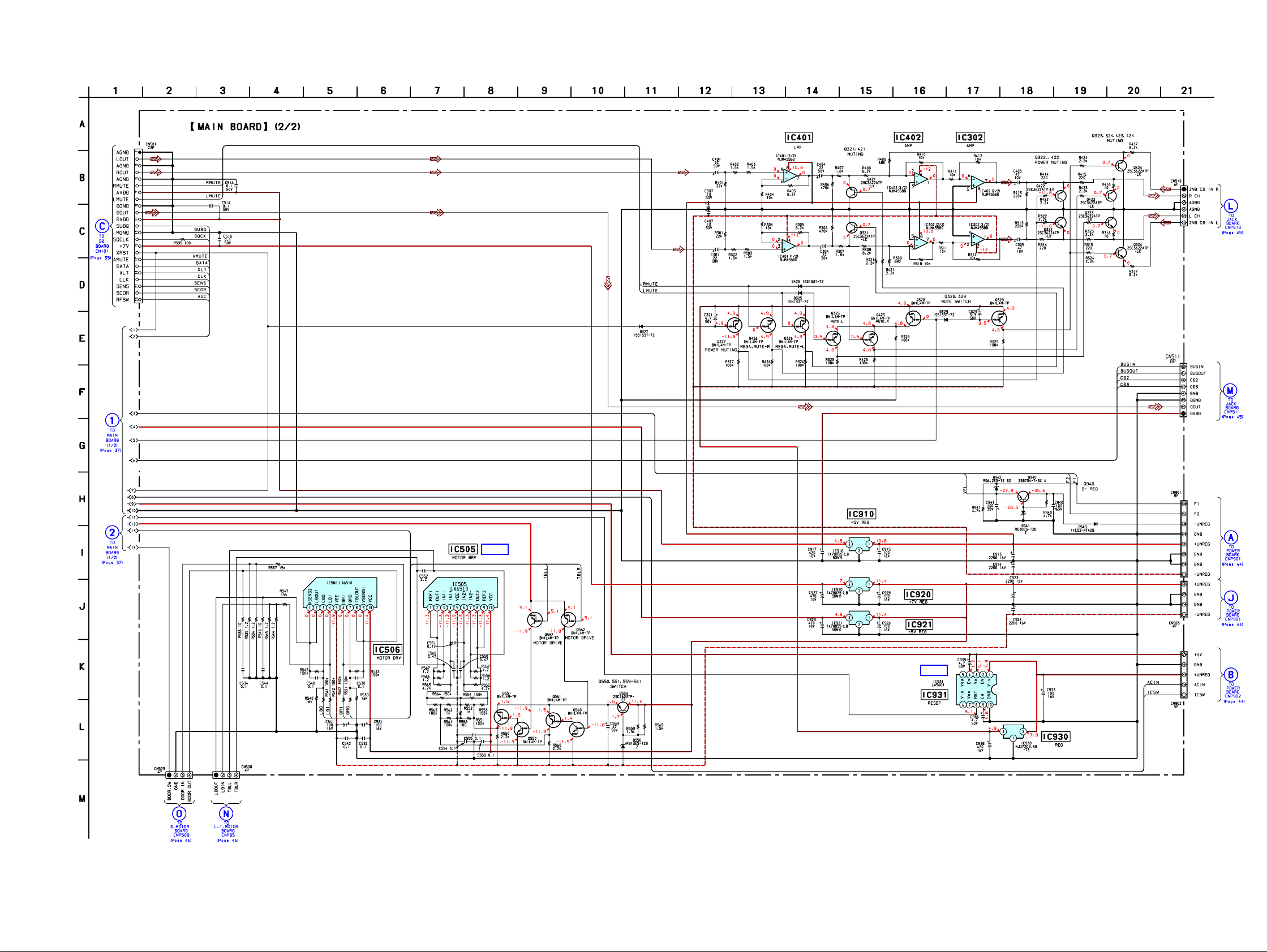
7-6. Schematic Diagram – MAIN Section (2/2) –
• See page 49 for IC Block Diagrams.
IC B/D
IC B/D
3838
Page 14
CDP-CX355
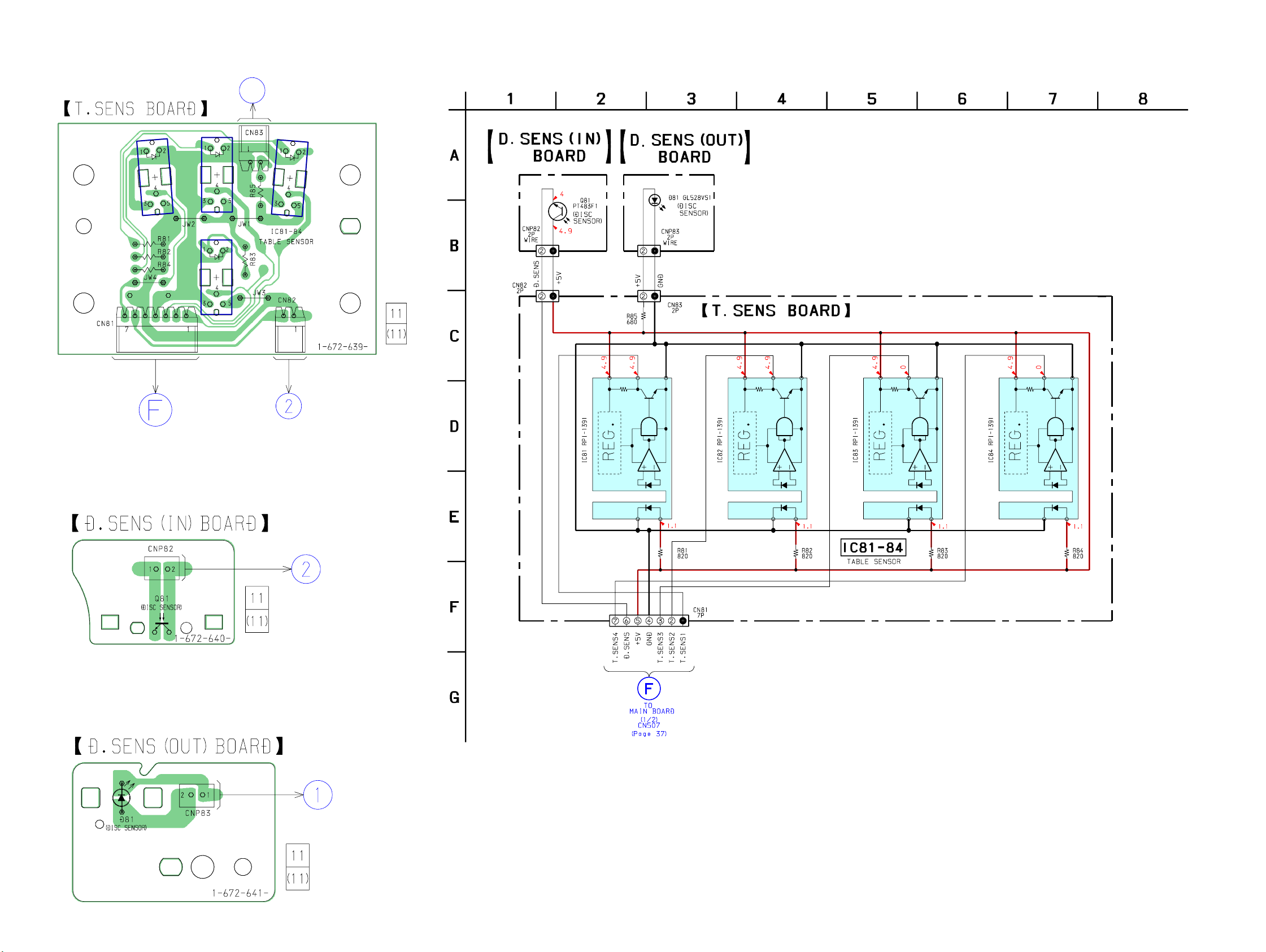
7-7. Printed Wiring Board – T.SENS Section –
• See page 31 for Circuit Boards Location.
1
IC84 IC82
IC83
IC81
7-10. Schematic Diagram – SENSOR Section –
543
543
543
543
TO
MAIN BOARD
CN507
(Page 36)
7-8. Printed Wiring Board – D.SENS (IN) Section –
• See page 31 for Circuit Boards Location.
7-9. Printed Wiring Board – D.SENS (OUT) Section –
• See page 31 for Circuit Boards Location.
21
21
21
21
3939
Page 15
CDP-CX355
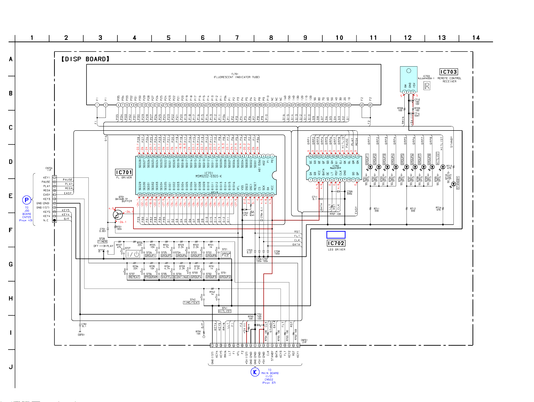
7-12. Schematic Diagram – DISPLAY Section –
• See page 49 for IC Block Diagrams.
IC B/D
4141
Page 16
CDP-CX355
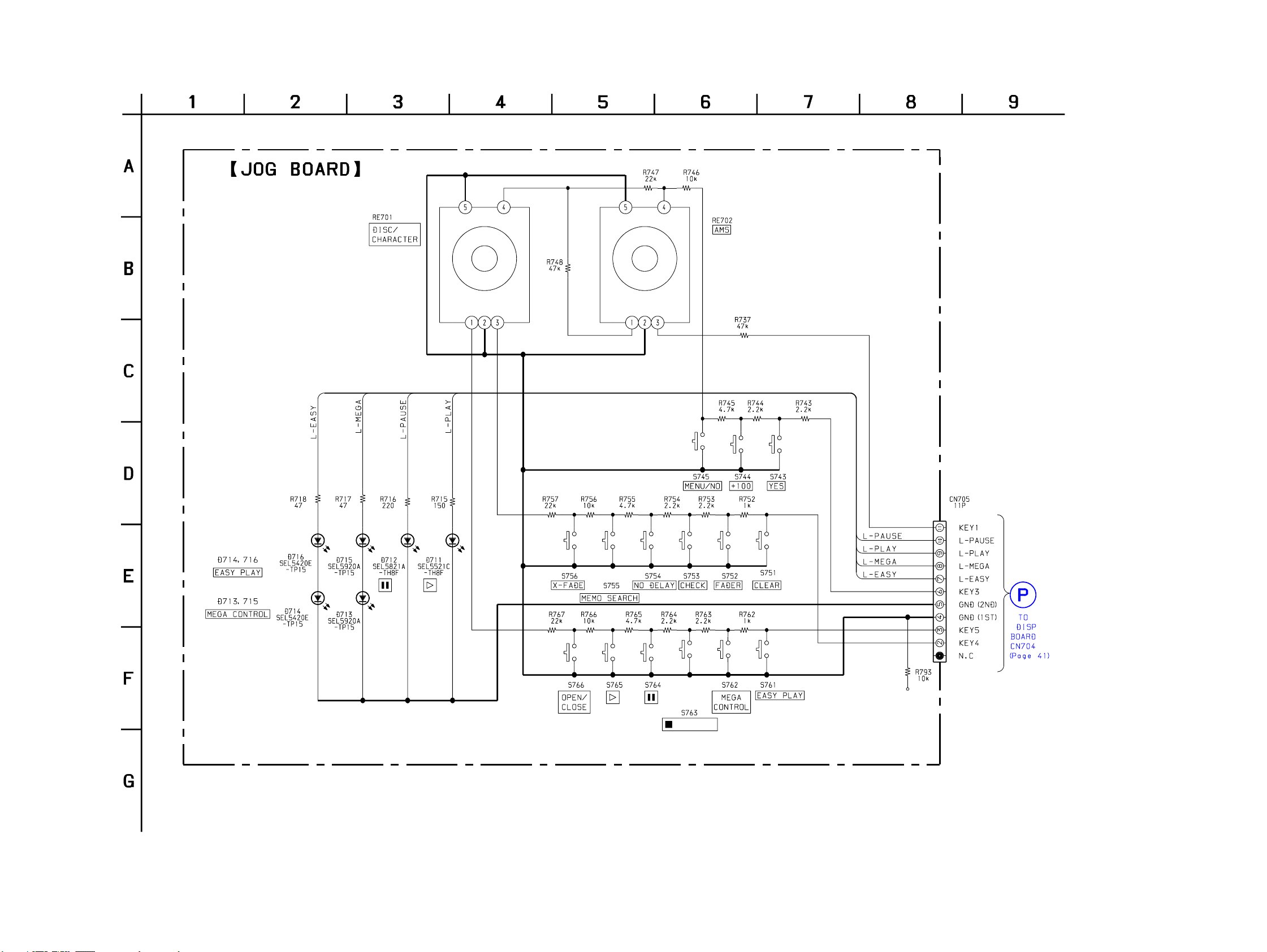
7-14. Schematic Diagram – JOG Section –
/DISC EJECT
4343
Page 17
CDP-CX355
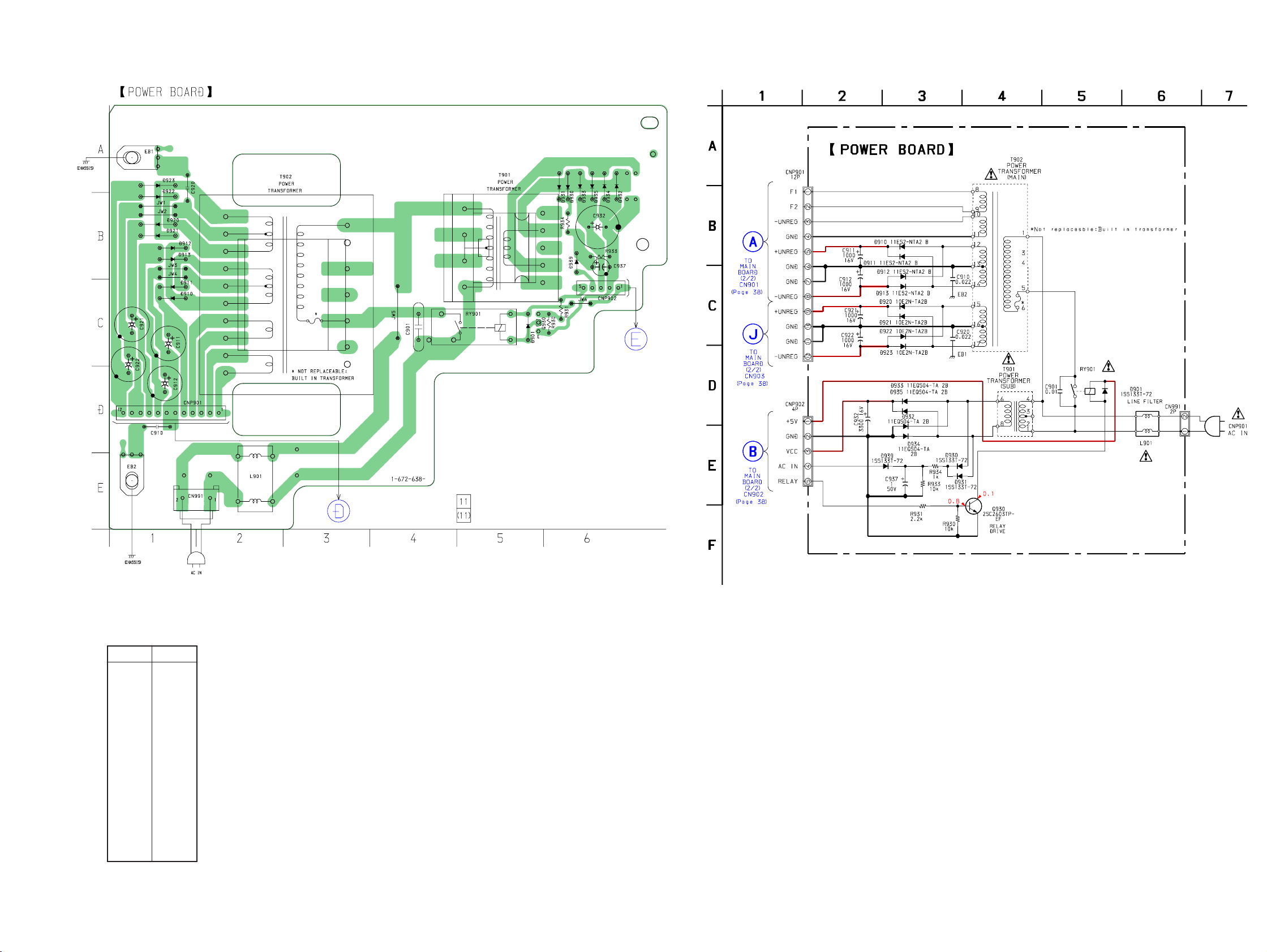
7-15. Printed Wiring Board – POWER Section –
• See page 31 for Circuit Boards Location.
7-16. Schematic Diagram – POWER Section –
TO
MAIN BOARD
CN902
(Page 36)
• Semiconductor
Location
Ref. No. Location
Q930 C-5
D901 C-5
D910 C-1
D911 C-1
D912 B-1
D913 B-1
D920 B-1
D921 B-1
D922 B-1
D923 A-1
D930 B-6
D931 B-6
D932 B-6
D933 B-6
D934 B-6
D935 B-6
D939 B-6
TO MAIN BOARD
CN901, 903
(Page 36)
CNP901
4444
Page 18
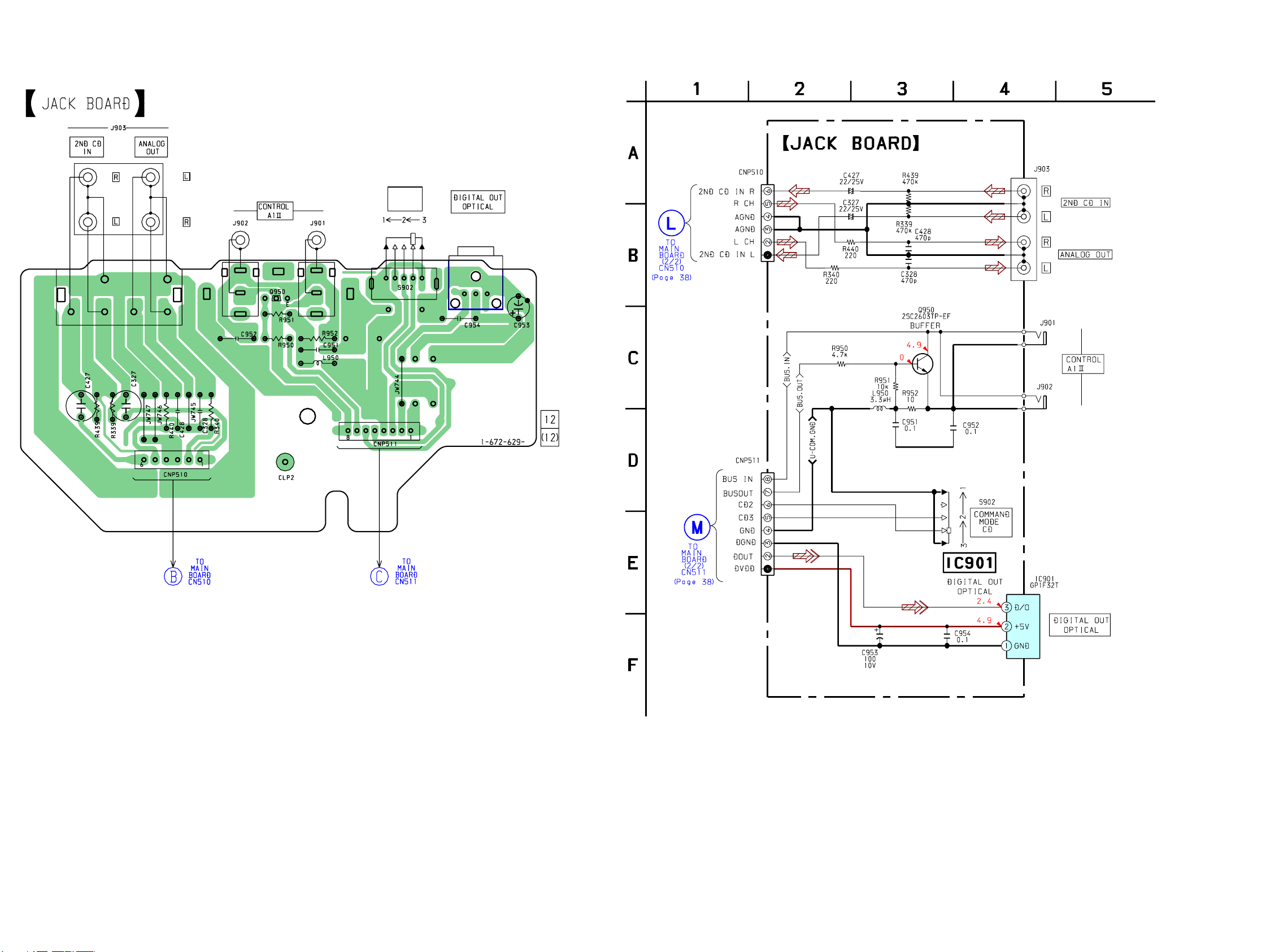
CDP-CX355
7-17. Printed Wiring Board – JACK Section – 7-18. Schematic Diagram – JACK Section –
• See page 31 for Circuit Boards Location.
COMMAND
MODE
CD
IC901
(Page 36)
(Page 36)
4545
Page 19
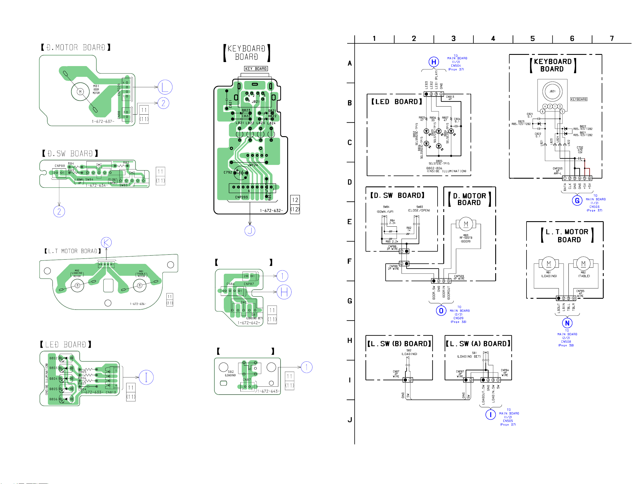
7-19. Printed Wiring Board – SWITCH/MOTOR Section – 7-20. Schematic Diagram – SWITCH/MOTOR Section –
• See page 31 for Circuit Boards Location.
TO
MAIN BOARD
CN509
(Page 36)
CDP-CX355
MAIN BOARD
CNP85
TO
CN508
(Page 36)
MAIN BOARD
(Page 36)
TO
CN504
TO
MAIN BOARD
CN503
(Page 36)
L.SW (A) BOARD
TO
MAIN BOARD
CN505
(Page 36)
L.SW (B) BOARD
4646
 Loading...