

Panasonic cu-xe9skua, cu-xe12skua service manual
Order No: PAPAMY1601004CE
O
O
N
CHEC
K
O
N
O
S
123
TIMER
TEM
P
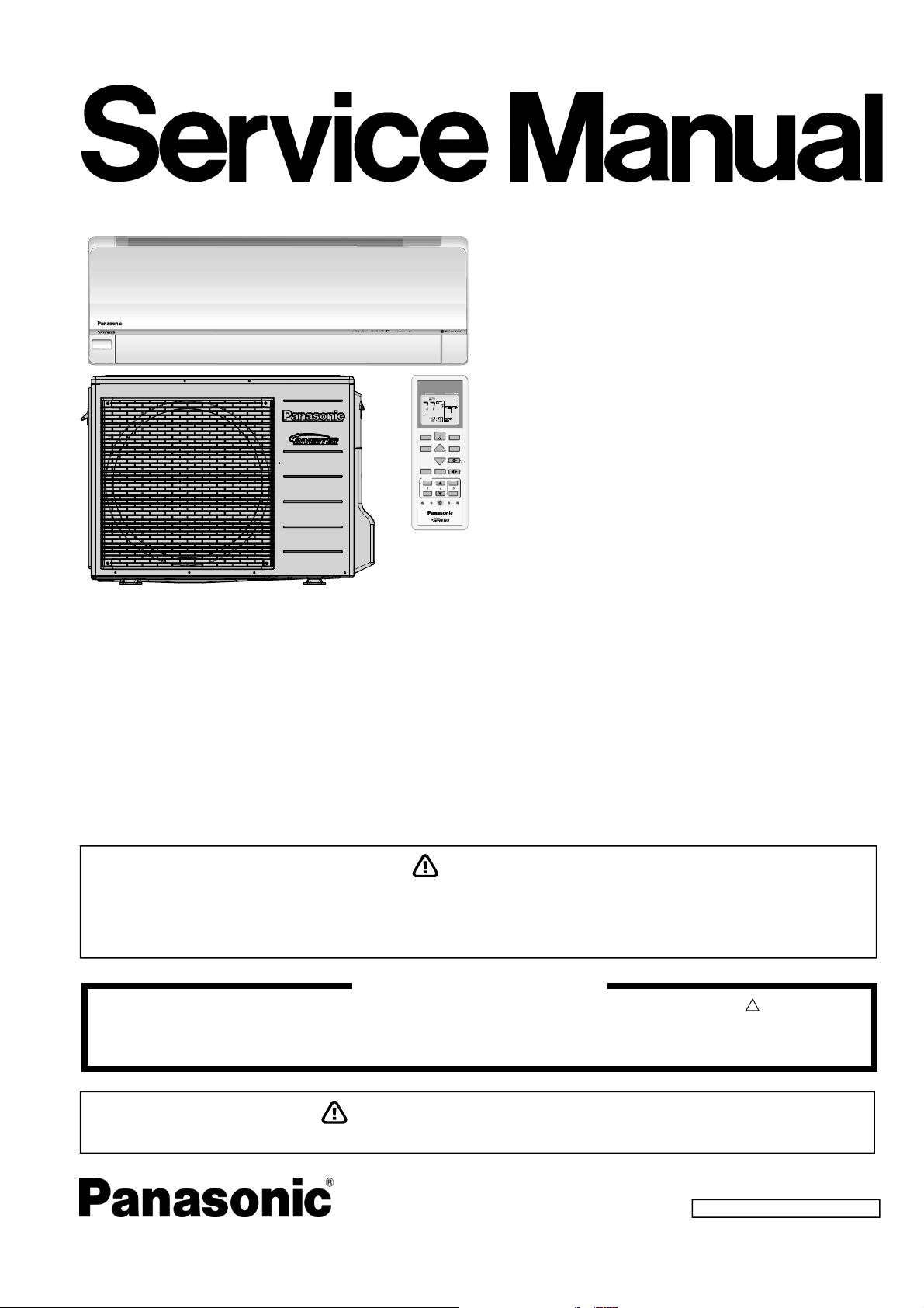
Air Conditioner
Indoor Unit Outdoor Unit
AIRCONDITIONER
MODE
ECONAVI
OFF/ON
FF/
MODE
TEMP
POWERFUL/
QUIET
FANSPEED
TIMER
ON
123
OFF
FF
CLOCK
SET CHECK RESET
COMFORT
AIRSWING
AC
CS-XE9SKUA
CS-XE12SKUA
AUTO
RFP
SET
ET
CANCEL
RC
CU-XE9SKUA
CU-XE12SKUA
Destination
U.S.A.
Canada
This service information is designed for experienced repair technicians only and is not designed for use by the general public.
It does not contain warnings or cautions to advise non-technical individuals of potential dangers in attempting to service a product.
Products powered by electricity should be serviced or repaired only by experienced professional technicians. Any attempt to service
or repair the products dealt with in this service information by anyone else could result in serious injury or death.
WARNING
IMPORTANT SAFETY NOTICE
There are special components used in this equipment which are important for safety. These parts are marked by in the Schematic
Diagrams, Circuit Board Diagrams, Exploded Views and Replacement Parts List. It is essential that these critical parts should be replaced
with manufacturer’s specified parts to prevent shock, fire or other hazards. Do not modify the original design without permission of
manufacturer.
In order to avoid frostbite, be assured of no refrigerant leakage during the installation or repairing of refrigerant circuit.
PRECAUTION OF LOW TEMPERATURE
© Panasonic Corporation 2016.
!

TABLE OF CONTENTS
1. Safety Precautions ............................................. 3
2. Specifications ..................................................... 5
3. Features ............................................................. 11
4. Location of Controls and Components .......... 12
4.1 Indoor Unit .................................................. 12
4.2 Outdoor Unit ............................................... 12
4.3 Remote Control .......................................... 12
5. Dimensions ....................................................... 13
5.1 Indoor Unit .................................................. 13
5.2 Outdoor Unit ............................................... 14
6. Refrigeration Cycle Diagram ........................... 15
7. Block Diagram .................................................. 16
8. Wiring Connection Diagram ............................ 17
8.1 Indoor Unit .................................................. 17
8.2 Outdoor Unit ............................................... 18
9. Electronic Circuit Diagram .............................. 19
9.1 Indoor Unit .................................................. 19
9.2 Outdoor Unit ............................................... 20
10. Printed Circuit Board ....................................... 21
10.1 Indoor Unit .................................................. 21
10.2 Outdoor Unit ............................................... 23
11. Installation Instruction ..................................... 24
15. Troubleshooting Guide ....................................50
15.1 Refrigeration Cycle System ........................50
15.2 Breakdown Self Diagnosis Function ...........52
15.3 Error Codes Table ......................................53
15.4 Self-diagnosis Method ................................55
16. Disassembly and Assembly Instructions ......82
16.1 Indoor Electronic Controllers,
Cross Flow Fan and Indoor Fan Motor
Removal Procedures ..................................82
16.2 Outdoor Electronic Controller Removal
Procedure ...................................................86
17. Technical Data ..................................................87
17.1 Cool Mode Performance Data ....................87
17.2 Heat Mode Performance Data ....................89
18. Service Data ......................................................90
18.1 Cool Mode Outdoor Air Temperature
Characteristic ..............................................90
18.2 Heat Mode Outdoor Air Temperature
Characteristic ..............................................92
18.3 Piping Length Correction Factor .................94
19. Exploded View and Replacement Parts
List .....................................................................95
19.1 Indoor Unit ..................................................95
19.2 Outdoor Unit ...............................................98
11.1 Select the Best Location ............................. 24
11.2 Indoor Unit .................................................. 25
11.3 Outdoor Unit ............................................... 29
12. Operation Control ............................................. 33
12.1 Basic Function ............................................ 33
12.2 Indoor Fan Motor Operation ....................... 34
12.3 Outdoor Fan Motor Operation .................... 35
12.4 Airflow Direction .......................................... 36
12.5 Quiet operation (Cooling Mode/Cooling
area of Dry Mode) ....................................... 37
12.6 Quiet Operation (Heating) .......................... 37
12.7 Powerful Mode Operation ........................... 38
12.8 Timer Control .............................................. 38
12.9 Auto Restart Control ................................... 38
12.10 Indication Panel .......................................... 39
12.11 Room Freeze Protection Function (RFP)
Operation .................................................... 39
12.12 AUTO COMFORT and ECONAVI
Operation .................................................... 39
13. Protection Control ............................................ 43
13.1 Protection Control For All Operations ......... 43
13.2 Protection Control For Cooling & Soft Dry
Operation .................................................... 45
13.3 Protection Control For Heating
Operation .................................................... 46
14. Servicing Mode ................................................. 48
14.1 Auto OFF/ON Button .................................. 48
14.2 Remote Control Button ............................... 49
2
1. Safety Precautions
Read the following “SAFETY PRECAUTIONS” carefully before perform any servicing.
Electrical work must be installed or serviced by a licensed electrician. Be sure to use the correct rating of the power plug and
main circuit for the model installed.
The caution items stated here must be followed because these important contents are related to safety. The meaning of each
indication used is as below. Incorrect installation or servicing due to ignoring of the instruction will cause harm or damage,
and the seriousness is classified by the following indications.
This indication shows the possibility of causing death or serious injury.
WARNING
CAUTION
The items to be followed are classified by the symbols:
Carry out test run to confirm that no abnormality occurs after the servicing. Then, explain to user the operation, care and
maintenance as stated in instructions. Please remind the customer to keep the operating instructions for future reference.
This indication shows the possibility of causing injury or damage to properties.
This symbol denotes item that is PROHIBITED from doing.
WARNING
1. Do not modify the machine, part, material during repairing service.
2. If wiring unit is supplied as repairing part, do not repair or connect the wire even only partial wire break. Exchange the whole wiring unit.
3. Do not wrench the fasten terminal. Pull it out or insert it straightly.
Engage dealer or specialist for installation and servicing. If installation of servicing done by the user is defective, it will cause water
4.
leakage, electrical shock or fire.
5. Install according to this installation instructions strictly. If installation is defective, it will cause water leakage, electric shock or fire.
Use the attached accessories parts and specified parts for installation and servicing. Otherwise, it will cause the set to fall, water leakage,
6.
fire or electrical shock.
Install at a strong and firm location which is able to withstand the set’s weight. If the strength is not enough or installation is not properly
7.
done, the set will drop and cause injury.
For electrical work, follow the local national wiring standard, regulation and the installation instruction. An independent circuit and single
8.
outlet must be used. If electrical circuit capacity is not enough or defect found in electrical work, it will cause electrical shock or fire.
This equipment must installed with an Earth Leakage Circuit Breaker (ELCB) or Ground Fault Current Interrupter (GFCI) or Appliance
9.
Leakage Current Interrupter (ALCI) that has been certified by an NRTL Certified Testing Agency and that is suitable for the voltages and
amperages involved. Otherwise, if may cause electrical shock and fire in case of equipment breakdown.
Do not use joint cable for indoor / outdoor connection cable. Use the specified Indoor/Outdoor connection cable, refer to installation
10.
instruction CONNECT THE CABLE TO THE INDOOR UNIT and connect tightly for indoor / outdoor connection. Clamp the cable so that
no external force will be acted on the terminal. If connecting or fixing is not perfect, it will cause heat up or fire at the connection.
Wire routing must be properly arranged so that control board cover is fixed properly. If control board cover is not fixed perfectly, it will
11.
cause heat-up or fire at the connection point of terminal, fire or electrical shock.
When install or relocate air conditioner, do not let any substance other than the specified refrigerant, eg. air etc. mix into refrigeration
12.
cycle (piping). (Mixing of air etc. will cause abnormal high pressure in refrigeration cycle and result in explosion, injury etc.).
Do not install outdoor unit near handrail of veranda. When installing air-conditioner unit at veranda of high rise building, child may climb
13.
up to outdoor unit and cross over the handrail and causing accident.
This equipment must be properly earthed. Earth line must not be connected to gas pipe, water pipe, earth of lightning rod and
14.
telephone. Otherwise, it may cause electric shock in case equipment breakdown or insulation breakdown.
15. Keep away from small children, the thin film may cling to nose and mouth and prevent breathing.
Do not use unspecified cord, modified cord, joint cord or extension cord for power supply cord. Do not share the single outlet with
16.
other electrical appliances. Poor contact, poor insulation or over current will cause electrical shock or fire.
Tighten the flare nut with torque wrench according to specified method. If the flare nut is over-tightened, after a long period, the
17.
flare may break and cause refrigerant gas leakage.
For R410A model, use piping, flare nut and tools which is specified for R410A refrigerant. Using of existing (R22) piping, flare nut
and tools may cause abnormally high pressure in the refrigerant cycle (piping), and possibly result in explosion and injury.
18.
Thickness or copper pipes used with R410A must be more than 1/32" (0.8 mm). Never use copper pipes thinner than 1/32"
(0.8 mm). It is desirable that the amount of residual oil is less than 0.0008 oz/ft (40 mg/10 m).
During installation, install the refrigerant piping properly before run the compressor. (Operation of compressor without fixing refrigeration
19.
piping and valves at opened condition will caused suck-in of air, abnormal high pressure in refrigeration cycle and result in explosion,
injury etc).
3
WARNING
During pump down operation, stop the compressor before remove the refrigeration piping. (Removal of compressor while compressor is
20.
operating and valves are opened will cause suck-in of air, abnormal high pressure in refrigeration cycle and result in explosion, injury etc.)
After completion of installation or service, confirm there is no leakage or refrigerant gas. It may generate toxic gas when the refrigerant
21.
contacts with fire.
22. Ventilate if there is refrigerant gas leakage during operation. It may cause toxic gas when refrigerant contacts with fire.
23. Do not insert your fingers or other objects into the unit, high speed rotating fan may cause injury.
24. Must not use other parts except original parts described in catalog and manual.
25. Using of refrigerant other than the specified type may cause product damage, burst and injury etc.
CAUTION
Do not install the unit at place where leakage of flammable gas may occur. In case gas leaks and accumulates at surrounding of
1.
the unit, it may cause fire.
Carry out drainage piping as mentioned in installation instructions. If drainage is not perfect, water may enter the room and damage the
2.
furniture.
Tighten the flare nut with torque wrench according to specified method. If the flare nut is over-tightened, after a long period, the flare may
3.
break and cause refrigerant gas leakage.
4. Do not touch outdoor unit air inlet and aluminium fin. It may cause injury.
5. Select an installation location which is easy for maintenance.
Pb free solder has a higher melting point than standard solder; typically the melting point is 50°F – 70°F (30°C – 40°C) higher.
6.
Please use a high temperature solder iron. In case of the soldering iron with temperature control, please set it to 700 ± 20°F (370 ± 10°C).
Pb free solder will tend to splash when heated too high (about 1100°F / 600°C).
Power supply connection to the room air conditioner.
Power supply cord shall be UL listed or CSA approved 3 conductor with minimum AWG14 wires.
Power supply point should be in an easily accessible place for power disconnection in case of emergency.
7.
In some countries, permanent connection of this air conditioner to the power supply is prohibited.
Fix power supply connection to a circuit breaker for permanent connection.
Use NRTL approved fuse or circuit breaker (rating refers to name plate) for permanent connection.
Do not release refrigerant during piping work for installation, servicing, reinstallation and during repairing a refrigerant parts.
8.
Take care of the liquid refrigerant, it may cause frostbite.
9. Installation or servicing work: It may need two people to carry out the installation or servicing work.
10. Do not install this appliance in a laundry room or other location where water may drip from the ceiling, etc.
11. Do not sit or step on the unit, you may fall down accidentally.
Do not touch the sharp aluminium fins or edges of metal parts.
12.
If you are required to handle sharp parts during installation or servicing, please wear hand glove.
Sharp parts may cause injury.
4
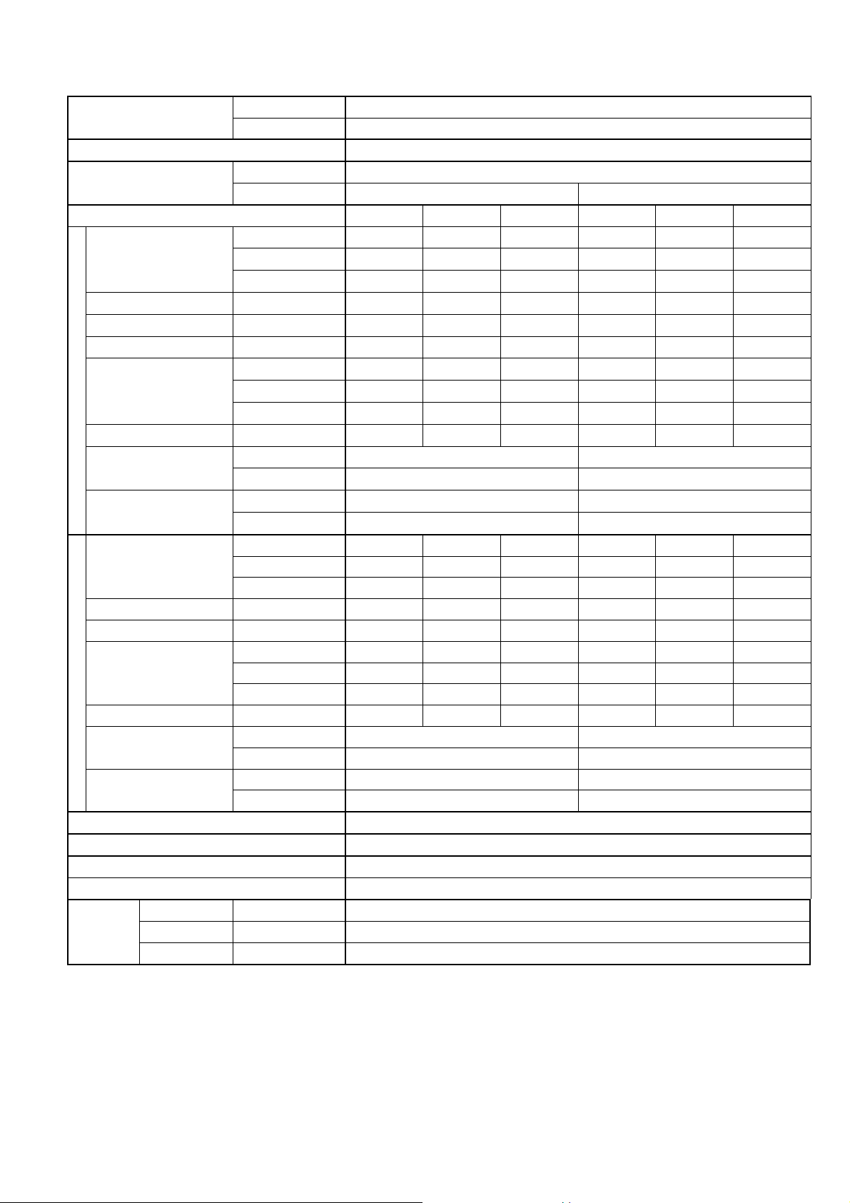
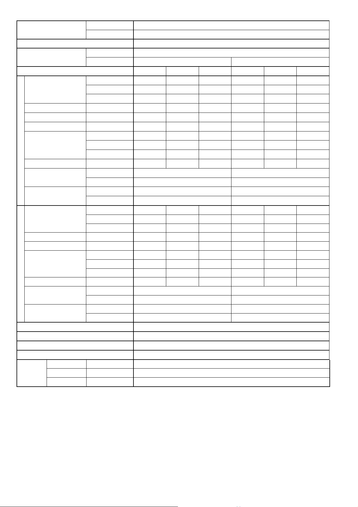
2. Specifications
Model
Performance Test Condition ARI
Power Supply
Min. Mid. Max. Min. Mid. Max.
Capacity
Running Current A – 2.70 – – 2.40 –
Input Power W 150 510 850 150 510 850
Annual Consumption kWh – – – – – –
Cooling
Indoor Noise (H / L / QLo)
Outdoor Noise (H / L / QLo)
Heating
Indoor Noise (H / L / QLo)
Outdoor Noise (H / L / QLo)
17°F: Rated Capacity (BTU/h) / I. Power (W) 8000 / 750
Compressor
EER
Power Factor % – 91 – – 92 –
Capacity
Running Current A – 3.50 – – 3.10 –
Input Power W 150 670 1.65k 150 670 1.65k
COP
Power Factor % – 92 – – 94 –
5°F: Max. Capacity (BTU/h) 11000
Max Current (A) / Max Input Power (W) 7.8 / 1.71k
Starting Current (A) 3.50
Type Hermetic Motor (Rotary)
Motor Type Brushless (4 poles)
Output Power W 700
Indoor CS-XE9SKUA
Outdoor CU-XE9SKUA
Phase, Hz Single, 60
V 208 230
kW 0.83 2.55 3.51 0.83 2.55 3.51
BTU/h 2800 8700 12000 2800 8700 12000
kcal/h – – – – – –
W/W 5.53 5.00 4.13 5.53 5.00 4.13
BTU/hW 18.65 17.05 14.10 18.65 17.05 14.10
kcal/hW – – – – – –
dB-A 42 / 25 / 20 42 / 25 / 20
Power Level dB 58 / – / – 58 / – / –
dB-A 48 / – / – 48 / – / –
Power Level dB 63 / – / – 63 / – / –
kW 0.89 3.21 5.29 0.89 3.21 5.29
BTU/h 3000 10900 18000 3000 10900 18000
kcal/h – – – – – –
W/W 5.93 4.78 3.21 5.93 4.78 3.21
BTU/hW 20.00 16.25 10.90 20.00 16.25 10.90
kcal/hW – – – – – –
dB-A 42 / 29 / 26 42 / 29 / 26
Power Level dB 58 / – / – 58 / – / –
dB-A 48 / – / – 48 / – / –
Power Level dB 63 / – / – 63 / – / –
5
Model
Indoor CS-XE9SKUA
Outdoor CU-XE9SKUA
Type Cross-Flow Fan
Material ASG33
Motor Type DC / Transistor (8-poles)
Input Power W 47.0
Output Power W 40
Cool rpm 570
Heat rpm 730
Cool rpm 660
Lo
Heat rpm 790
Cool rpm 920
Heat rpm 990
Cool rpm 1180
Hi
Heat rpm 1190
Cool rpm 1250
Heat rpm 1340
Indoor Fan
Speed
QLo
Me
SHi
Type Propeller Fan
Material PP
Motor Type DC (8-poles)
Input Power W –
Outdoor Fan
Output Power W 40
Speed Hi
Cool rpm 600
Heat rpm 670
Min Circuit Ampacity 15.0
Max. Overcurrent Protection 15.0
SEER / HSPF 30.60 / 14.00
Moisture Removal L/h (Pt/h) 0.5 (1.3)
3
/min (ft3/min) 5.77 (203)
3
/min (ft3/min) 6.88 (242)
3
/min (ft3/min) 10.09 (356)
3
/min (ft3/min) 13.3 (470)
3
/min (ft3/min) 14.16 (500)
3
/min (ft3/min) 34.6 (1220) 34.6 (1220)
Indoor
Airflow
Outdoor
Airflow
QLo
Lo
Me
Hi
SHi
Hi
Cool m
Heat m3/min (ft3/min) 7.79 (275)
Cool m
Heat m3/min (ft3/min) 8.53 (301)
Cool m
Heat m3/min (ft3/min) 11.01 (388)
Cool m
Heat m3/min (ft3/min) 13.5 (475)
Cool m
Heat m3/min (ft3/min) 15.36 (540)
Cool m
Heat m3/min (ft3/min) 39.1 (1380) 39.1 (1380)
Control Device Expansion Valve
Refrigeration
Cycle
Refrigerant Oil cm3 FV50S (320)
Refrigerant Type g (oz) R410A, 1150 (40.6)
Height(I/D / O/D) mm (inch) 295 (11-5/8) / 695 (27-3/8)
Dimension
Width (I/D / O/D) mm (inch) 870 (34-9/32) / 875 (34-15/32)
Depth (I/D / O/D) mm (inch) 255 (10-1/16) / 320 (12-5/8)
Weight Net (I/D / O/D) kg (lb) 11 (24) / 44 (97)
6
Model
Pipe Diameter (Liquid / Gas) mm (inch) 6.35 (1/4) / 9.52 (3/8)
Standard length m (ft) 7.5 (24.6)
Length range (min – max) m (ft) 3 (9.8) ~ 20 (65.6)
I/D & O/D Height different m (ft) 15.0 (49.2)
Piping
Additional Gas Amount g/m (oz/ft) 20 (0.2)
Length for Additional Gas m (ft) 7.5 (24.6)
Drain Hose
Indoor Heat
Exchanger
Outdoor
Heat
Exchanger
Air Filter
Power Supply Cord A Nil
Indoor
Operation
Range
Outdoor
Operation
Range
1. Cooling capacities are based on indoor temperature of 80°F (26.7°C) DRY BULB, 67°F (19.4°C) WET BULB and outdoor air temperature of
95°F (35°C) DRY BULB, 75°F (23.8°C) WET BULB.
2. Heating capacities are based on indoor temperature of 70°F (21.1°C) DRY BULB, 60°F (15.6°C) WET BULB and outdoor air temperature of
47°F (8.3°C) DRY BULB, 43°F (6.1°C) WET BULB.
3. 17°F (-8.3°C) Heating Capacity and Input Power measured at 230V, indoor temperature 70°F (21.1°C), outdoor 17/15°F (-8.3/-9.4°C).
4. 5°F (-15°C) Heating Capacity measured at 230V, indoor temperature 70°F (21.1°C), outdoor 5°F (-15°C/-).
5. Specifications are subjected to change without prior notice for further improvement.
Inner Diameter mm (inch) 16.7 (5/8)
Length mm(inch) 650 (25-5/8)
Fin Material Aluminium (Pre Coat)
Fin Type Slit Fin
Row × Stage × FPI 2 × 17 × 21
Size (W × H × L) mm (inch) 636.5 × 357 × 25.4 (25-1/16 × 14-1/16 × 1)
Fin Material Aluminium / Blue Coated
Fin Type Corrugated Fin
Row × Stage × FPI 2 × 31 × 18
Size (W × H × L) mm (inch) 36.4 × 651 × 854.5:824.5 (1-7/16 × 25-11/16 × 33-11/16:32-15/32)
Material Polypropelene
Type One-touch
Power Supply Outdoor
Thermostat Electronic Control
Protection Device Electronic Control
Dry Bulb Wet Bulb
Cooling
Heating
Cooling
Heating
Indoor CS-XE9SKUA
Outdoor CU-XE9SKUA
Maximum °F/°C 89.6/32 73.4/23
Minimum °F/°C 60.8/16 51.8/11
Maximum °F/°C 86.0/30 –/–
Minimum °F/°C 60.8/16 –/–
Maximum °F/°C 114.8/46 78.8/26
Minimum °F/°C 0.0/-17.8 –/–
Maximum °F/°C 75.2/24 64.4/18
Minimum °F/°C -15/-26 -2.2/-19
7
Model
Performance Test Condition ARI
Power Supply
Min. Mid. Max. Min. Mid. Max.
Capacity
Running Current A – 4.10 – – 3.70 –
Input Power W 150 780 1.05k 150 780 1.05k
Annual Consumption kWh – – – – – –
Cooling
Indoor Noise (H / L / QLo)
Outdoor Noise (H / L / QLo)
Heating
Indoor Noise (H / L / QLo)
Outdoor Noise (H / L / QLo)
17°F: Rated Capacity (BTU/h) / I. Power (W) 10400 / 1.05k
Compressor
EER
Power Factor % – 91 – – 92 –
Capacity
Running Current A – 4.90 – – 4.40 –
Input Power W 150 950 2.10k 150 950 2.10k
COP
Power Factor % – 93 – – 94 –
5°F: Max. Capacity (BTU/h) 12500
Max Current (A) / Max Input Power (W) 9.5 / 2.15k
Starting Current (A) 4.90
Type Hermetic Motor (Rotary)
Motor Type Brushless (4 poles)
Output Power W 700
Indoor CS-XE12SKUA
Outdoor CU-XE12SKUA
Phase, Hz Single, 60
V 208 230
kW 0.83 3.36 4.10 0.83 3.36 4.10
BTU/h 2800 11500 14000 2800 11500 14000
kcal/h – – – – – –
W/W 5.53 4.30 3.90 5.53 4.30 3.90
BTU/hW 18.65 14.70 13.30 18.65 14.70 13.30
kcal/hW – – – – – –
dB-A 45 / 28 / 20 45 / 28 / 20
Power Level dB 61 / – / – 61 / – / –
dB-A 49 / – / – 49 / – / –
Power Level dB 64 / – / – 64 / – / –
kW 0.89 3.99 6.72 0.89 3.99 6.72
BTU/h 3000 13600 23000 3000 13600 23000
kcal/h – – – – – –
W/W 5.93 4.20 3.20 5.93 4.20 3.20
BTU/hW 20.00 14.30 10.95 20.00 14.30 10.95
kcal/hW – – – – – –
dB-A 44 / 35 / 32 44 / 35 / 32
Power Level dB 60 / – / – 60 / – / –
dB-A 49 / – / – 49 / – / –
Power Level dB 64 / – / – 64 / – / –
8
Model
Indoor CS-XE12SKUA
Outdoor CU-XE12SKUA
Type Cross-Flow Fan
Material ASG33
Motor Type DC / Transistor (8-poles)
Input Power W 47.0
Output Power W 40
Cool rpm 570
Heat rpm 870
Cool rpm 710
Lo
Heat rpm 950
Cool rpm 990
Heat rpm 1100
Cool rpm 1280
Hi
Heat rpm 1250
Cool rpm 1350
Heat rpm 1340
Indoor Fan
Speed
QLo
Me
SHi
Type Propeller Fan
Material PP
Motor Type DC (8-poles)
Input Power W –
Outdoor Fan
Output Power W 40
Speed Hi
Cool rpm 600
Heat rpm 730
Min Circuit Ampacity 15.0
Max. Overcurrent Protection 20.0
SEER / HSPF 26.20 / 12.50
Moisture Removal L/h (Pt/h) 1.1 (2.3)
3
/min (ft3/min) 5.83 (205)
3
/min (ft3/min) 7.58 (268)
3
/min (ft3/min) 11.08 (391)
3
/min (ft3/min) 14.7 (520)
3
/min (ft3/min) 15.57 (550)
3
/min (ft3/min) 35.9 (1265) 35.9 (1265)
Indoor
Airflow
Outdoor
Airflow
QLo
Lo
Me
Hi
SHi
Hi
Cool m
Heat m3/min (ft3/min) 9.56 (338)
Cool m
Heat m3/min (ft3/min) 10.56 (373)
Cool m
Heat m3/min (ft3/min) 12.43 (439)
Cool m
Heat m3/min (ft3/min) 14.3 (505)
Cool m
Heat m3/min (ft3/min) 15.42 (544)
Cool m
Heat m3/min (ft3/min) 44.0 (1555) 44.0 (1555)
Control Device Expansion Valve
Refrigeration
Cycle
Refrigerant Oil cm3 FV50S (320)
Refrigerant Type g (oz) R410A, 1150 (40.6)
Height(I/D / O/D) mm (inch) 295 (11-5/8) / 695 (27-3/8)
Dimension
Width (I/D / O/D) mm (inch) 870 (34-9/32) / 875 (34-15/32)
Depth (I/D / O/D) mm (inch) 255 (10-1/16) / 320 (12-5/8)
Weight Net (I/D / O/D) kg (lb) 11 (24) / 44 (97)
9
Model
Pipe Diameter (Liquid / Gas) mm (inch) 6.35 (1/4) / 12.70 (1/2)
Standard length m (ft) 7.5 (24.6)
Length range (min – max) m (ft) 3 (9.8) ~ 20 (65.6)
I/D & O/D Height different m (ft) 15.0 (49.2)
Piping
Additional Gas Amount g/m (oz/ft) 20 (0.2)
Length for Additional Gas m (ft) 7.5 (24.6)
Drain Hose
Indoor Heat
Exchanger
Outdoor
Heat
Exchanger
Air Filter
Power Supply Cord A Nil
Indoor
Operation
Range
Outdoor
Operation
Range
1. Cooling capacities are based on indoor temperature of 80°F (26.7°C) DRY BULB, 67°F (19.4°C) WET BULB and outdoor air temperature of
95°F (35°C) DRY BULB, 75°F (23.8°C) WET BULB.
2. Heating capacities are based on indoor temperature of 70°F (21.1°C) DRY BULB, 60°F (15.6°C) WET BULB and outdoor air temperature of
47°F (8.3°C) DRY BULB, 43°F (6.1°C) WET BULB.
3. 17°F (-8.3°C) Heating Capacity and Input Power measured at 230V, indoor temperature 70°F (21.1°C), outdoor 17/15°F (-8.3/-9.4°C).
4. 5°F (-15°C) Heating Capacity measured at 230V, indoor temperature 70°F (21.1°C), outdoor 5°F (-15°C/-).
5. Specifications are subjected to change without prior notice for further improvement.
Inner Diameter mm (inch) 16.7 (5/8)
Length mm (inch) 650 (25-5/8)
Fin Material Aluminium (Pre Coat)
Fin Type Slit Fin
Row × Stage × FPI 2 × 17 × 21
Size (W × H × L) mm (inch) 636.5 × 357 × 25.4 (25-11/16 × 14-1/16 × 1)
Fin Material Aluminium / Blue Coated
Fin Type Corrugated Fin
Row × Stage × FPI 2 × 31 × 18
Size (W × H × L) mm (inch) 36.4 × 651 × 854.5:824.5 (1-7/16 × 25-11/16 × 33-11/16:32-15/32)
Material Polypropelene
Type One-touch
Power Supply Outdoor
Thermostat Electronic Control
Protection Device Electronic Control
Dry Bulb Wet Bulb
Cooling
Heating
Cooling
Heating
Indoor CS-XE12SKUA
Outdoor CU-XE12SKUA
Maximum °F/°C 89.6/32 73.4/23
Minimum °F/°C 60.8/16 51.8/11
Maximum °F/°C 86.0/30 –/–
Minimum °F/°C 60.8/16 –/–
Maximum °F/°C 114.8/46 78.8/26
Minimum °F/°C 0.0/-17.8 –/–
Maximum °F/°C 75.2/24 64.4/18
Minimum °F/°C -15/-26 -2.2/-19
10

3. Features
Inverter Technology
o Wider output power range
o Energy saving
o Quick Cooling
o Quick Heating
o More precise temperature control
Environment Protection
o Non-ozone depletion substances refrigerant (R410A)
Long Installation Piping
o Long piping up to 65.6ft (20 meters) during single split connection only
Easy to use remote control
Quality Improvement
o Random auto restart after power failure for safety restart operation
o Gas leakage protection
o Prevent compressor reverse cycle
o Inner protector to protect compressor
o Noise prevention during soft dry operation
Operation Improvement
o Quiet mode to reduce the indoor unit operating sound
o Powerful mode to reach the desired room temperature quickly
o 24-hour timer setting
o RFP (Room Freeze Protection) operation is designed to circulate the air in High mode for monitoring the
temperature. Used in spaces that are unoccupied during the winter, for the purpose of protecting any
equipment or appliances which may be destroyed as a result of freezing temperature.
Serviceability Improvement
o Breakdown Self Diagnosis function
11
4. Location of Controls and Components
A
A
O
O
N
C
C
K
O
N
O
S
1
2
3
T
I
M
E
R
T
E
M
P
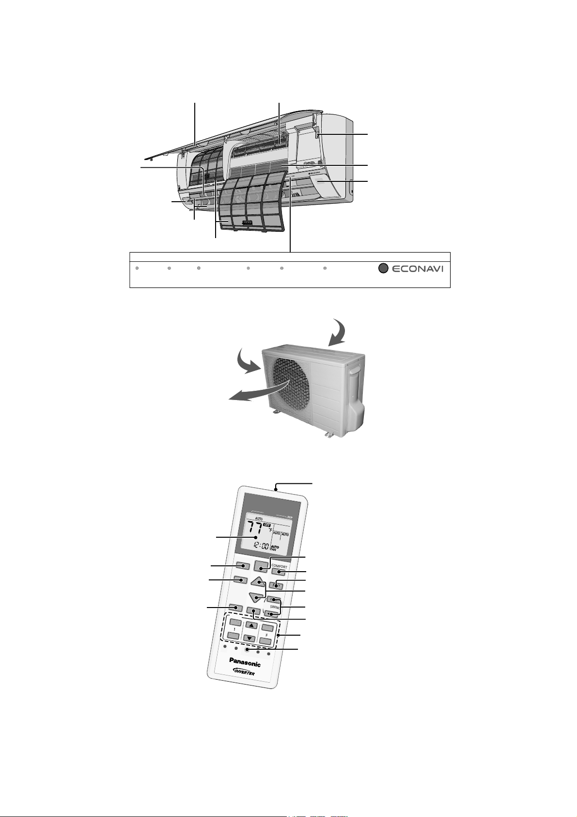
4.1 Indoor Unit
Front panel
Horizontal airflow
direction louver
Do not adjust by hand.
Human activity
sensor
ir purifying filter
Auto OFF/ON button
Use when remote control is misplaced
or a malfunction occurs.
Aluminium fin
Remote Control Receiver
Distances: 26ft/8m
Vertical airflow direction louver
Do not adjust by hand.
POWER
(Green)
(Orange) (Green)
4.2 Outdoor Unit
4.3 Remote Control
TIMER
Air Filters
AUTO COMFORT
(Green)
Air inlet (side)
ir outlet
RFP
(Green)
A
I
R
C
O
N
M
O
Indicator
D
I
T
D
E
POWERFUL
(Orange)
Air inlet (rear)
I
O
N
E
R
QUIET
(Orange)
Transmitter
LCD display
ECONAVI operation
Operation mode
Powerful/Quiet
operation
E
C
O
N
A
V
I
A
O
U
F
F
F
F
/
/
O
N
C
O
M
M
O
D
E
P
O
W
E
R
F
U
L
/
Q
U
I
E
T
T
I
M
E
R
O
N
1
O
F
F
F
F
S
E
T
C
H
H
E
E
C
K
C
L
R
F
P
T
E
M
P
A
I
R
S
W
I
N
F
A
O
C
K
G
N
S
P
E
E
D
S
E
E
T
T
2
3
C
A
N
C
E
L
A
C
R
C
R
E
S
E
T
OFF/ON
T
O
F
O
R
T
Auto Comfort operation
Room freeze protection operation
Temperature setting
Airflow direction adjustment
Fan speed selection
Timer setting
Clock setting
12
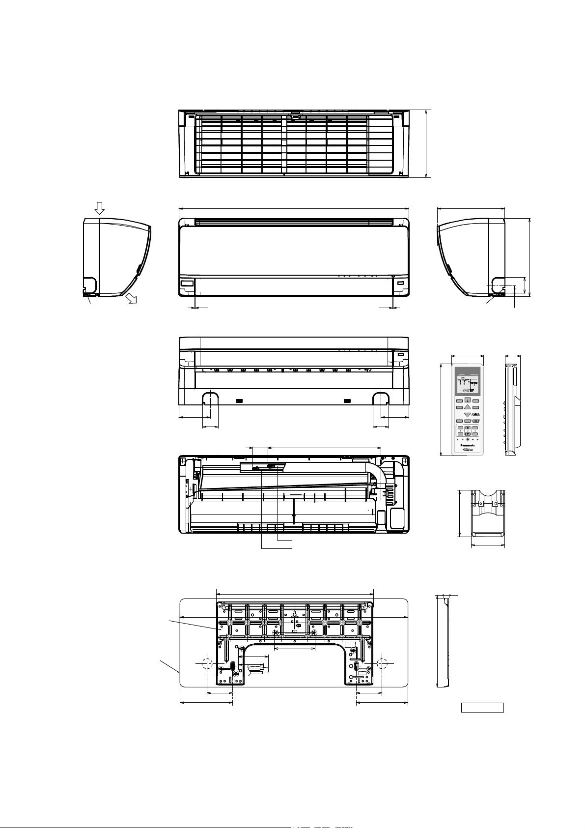
5. Dimensions
O
ONOFFS
123
TIMER
TEM
P
5.1 Indoor Unit
<Top View>
10-1/6 (255)
<Side View> <Side View>
Air intake
direction
Left piping
hole
Air outlet
direction
<Front View>
34-9/32 (870)
1/16-3/32 (1-2) 1/16-3/32 (1-2)
10-1/16 (255)
Right piping
hole
<Bottom View>
<Remote Control>
2-5/16 (59)
AIR CONDITI ONER
MODE
AUTO
ECONAVI
COMFORT
OFF/ON
FF/ON
MODE
RFP
4-3/4 (119.1)
2-3/16 (60) 2-3/16 (60)
<Rear View>
1-5/8-2-7/16 (41-61)
16-3/16 (410)
4-1/32 (105.8)
TEMP
POWERFUL/
AIRSWING
QUIET
FANSPEED
TIMER
ON
SET
123
OFF
CLOCK
SET CHECK RESET
CHECK
ET
CANCEL
AC
RC
6-5/16 (160)
<Remote Control Holder>
11-5/8 (295)
2-3/16 (60)
1-11/16 (41.5)
7/8 (22)
Gas side
Liquid side
Relative position between the indoor unit and the installation plate <Front View>
Installation
plate
Indoor unit
external
dimensions
line
19-19/32 (497.2)
17 (432)17-9/32 (439)
Left
piping
hole
3-3/4 (95)
1-11/16 (43)
5-1/16 (128)
5-1/16 (128) 5-1/16 (128)
Right
piping
hole
9-17/32 (241.5) 9-17/32 (241.5)
41/64 (16.5)
13
3-7/16 (87)
2-17/32 (64)
10-3/16 (264.2)
Unit : inch (mm)
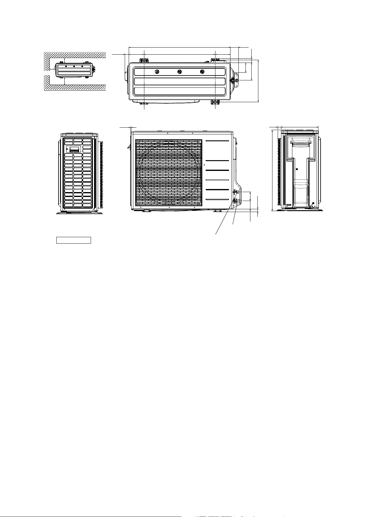
5.2 Outdoor Unit
<TopView
>
Space necessary for
installation
3-15/16 (10 cm)
1-3/8 (34.5)
5-3/16 (131)
34-15/32 (875 )
24-5/32 (613 )
5-3/16 (131)
2-25/32 (70)
1-1/2 (38)
3-15/16 (10 cm)
Anchor Bolt Pitch
14-7/32 (360.5) x 24-5/32 (613)
Unit: inch (mm)
43 (100 cm)
<Side View> <Front View>
3/8 (9.5)
3-5/32 (85)
5-31/32 (151)
14-7/32 (360 .5)
1-3/16 (30)
2-31/32 (75)
63/64 (25)
2-25/32 (70.4)
3-way valve at Gas side
(Low Pressure)
2-way valve at Liquid side
(High Pressure)
<Side View>
12-5/8 (320)
27-3/8 (695)
14
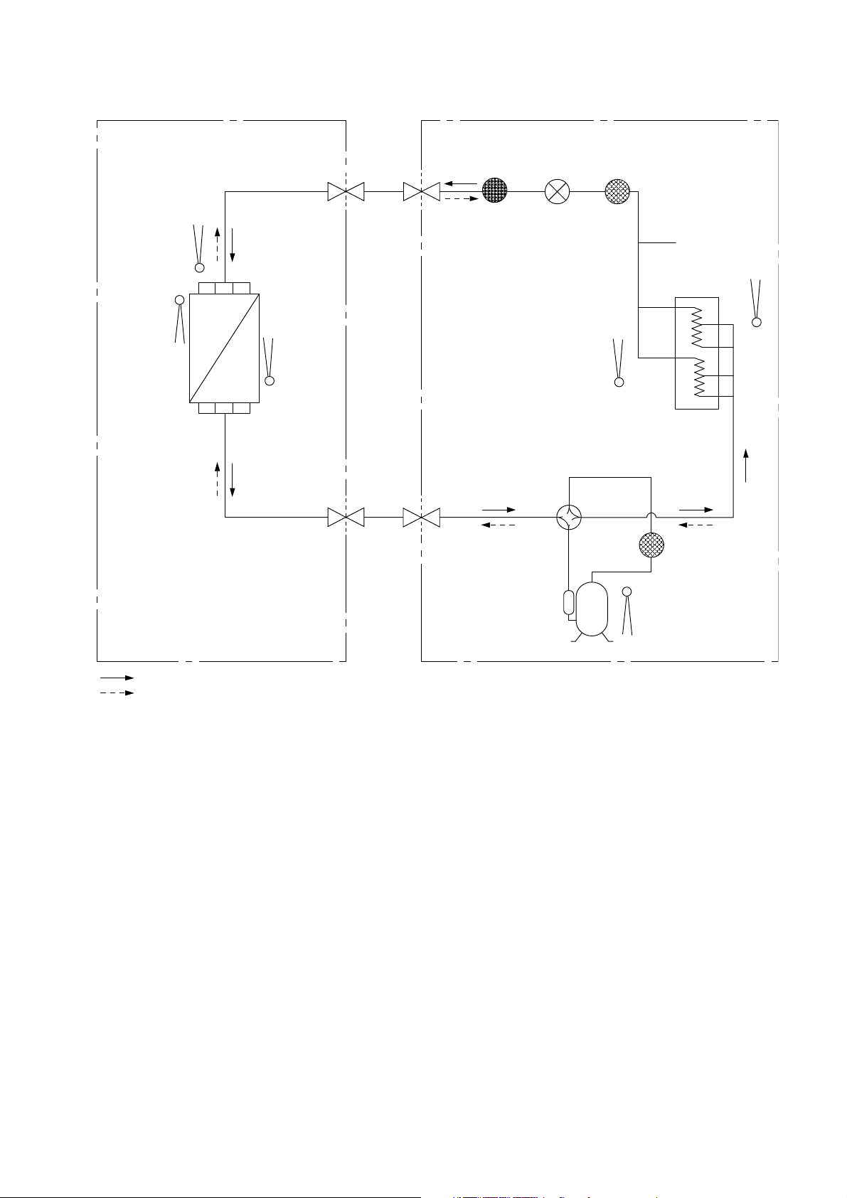
6. Refrigeration Cycle Diagram
INDOOR OUTDOOR
PIPE
TEMP.
SENSOR 2
INTAKE
AIR
TEMP.
SENSOR
HEAT EXCHANGER
(EVAPORATOR)
PIPE
TEMP.
SENSOR 1
LIQUID
SIDE
2-WAY
VALV E
GAS
SIDE
3-WAY
VALV E
MUFFLER
4-WAYS VALVE
EXPANSION
VALV E
STRAINER
PIPE
TEMP.
SENSOR
PROCESS
TUBE
HEAT
EXCHANGER
(CONDENSER)
RECEIVER
AIR
TEMP.
SENSOR
COOLING
HEATING
COMPRESSOR
TEMP. SENSOR
COMPRESSOR
15
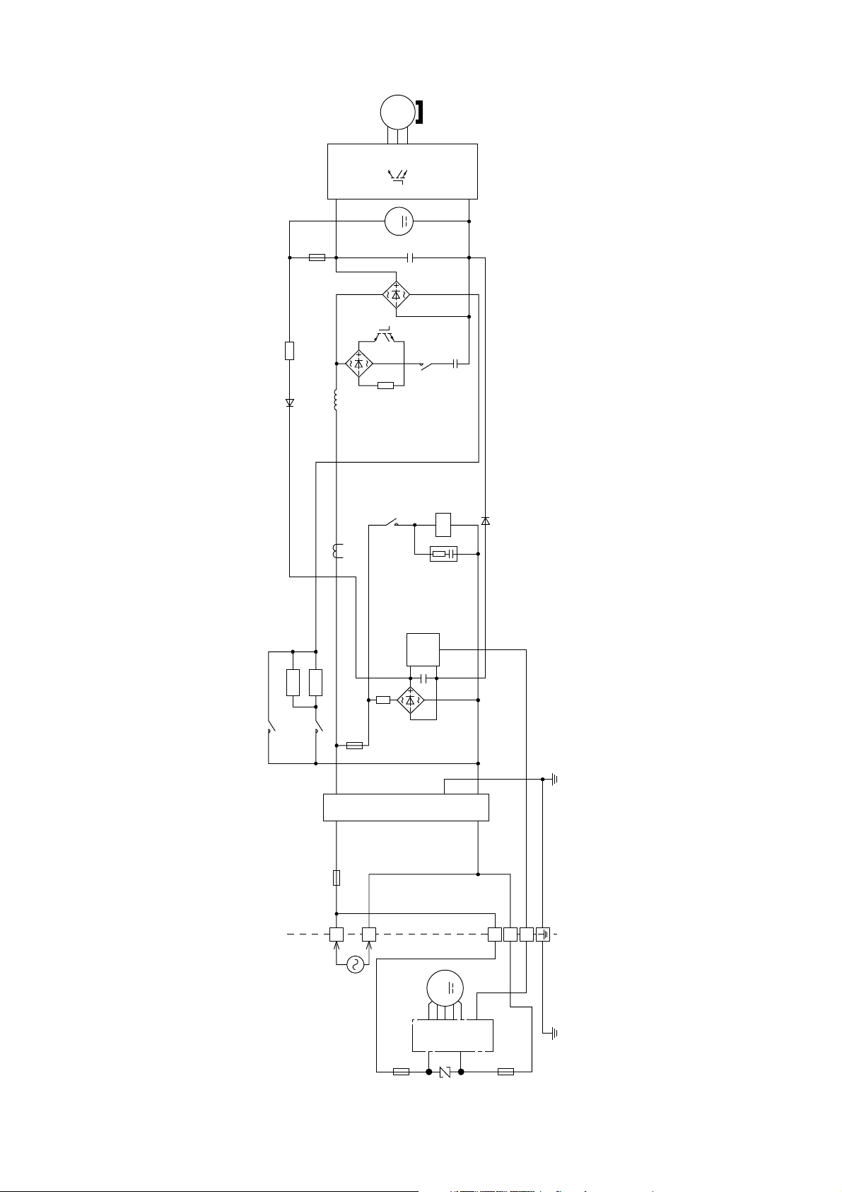
7. Block Diagram
3~
MS
V
U
W
NTC
TH2
P
N
M
FUSE1
DB1
REACTOR
CT400
+
DB3
Q1
RY-C
RY-HOT
4-WAYS VALVE
CR3
+
PTC1
RY-PWR
PTC2
RY-AC
TH1
NTC
DB2
FUSE2
NOISE FILTER
FUSE3
SC
123
TEMPERATURE
FUSE
L2
L1
M
(INDOOR UNIT) (OUTDOOR UNIT)
SINGLE PHASE
POWER SUPPLY
1Ø208/230V, 60Hz
FUSE 301
16
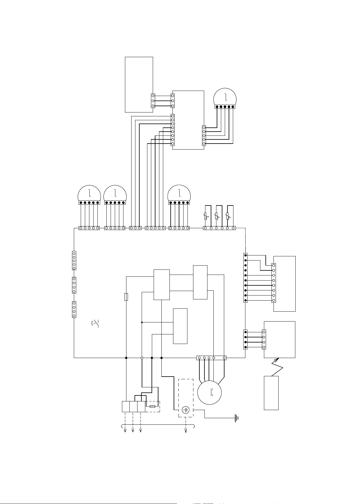
8. Wiring Connection Diagram
TOOUTDOORUNIT
8.1 Indoor Unit
3
(ECO SENSOR)
(GREEN)
CN-SENS
UP DOWN
LOUVER MOTOR
ELECTRONIC CONTROLLER
LEFT RIGHT
(OUTER)
LOUVER MOTOR
1
MOTOR
ECO SENSOR
1
WHT
WHT
WHT
3
CN-SENS
1
CN-MSSTM
8
UP DOWN
LOUVER MOTOR
(WHT)
ELECTRONIC
(WHT)
CN-STM
(INNER)
CONTROLLER
(COMPARATOR)
51
(GREEN)
PNK
M
5
1
RED
ORG
YLW
BRW
REMARKS
BLU:BLUE PNK:PINK
BRW:BROWN ORG:ORANGE
BLK:BLACK YLW:YELLOW
WHT:WHITE GRY:GRAY
RED:RED GRN:GREEN
YLW/GRN:YELLOW/GREEN
M
1
PNK
BRW1ORG
RED5YLW
CN-CNT
51
14
CN-RMT
14
CN-CLN
ELECTRONIC
CONTROLLER
5
(WHT)
CN-STM1
(WHT)
(WHT)
(GRN)
(MAIN)
BRW1ORG
AUTO SW
M
1
RED5YLW
CN-STM2
(SW01)
M
5
1
PNK
5
(YLW)
WHT
WHT
WHT
3
(WHT)
CN-MSENS
FUSE301
T3.15A L250V
AC303(WHT)
WHT
1
1
AC304(RED)
WHT
WHT
WHT
(GRN)
CN-STM3
G301(GRN)
WHT
5
CIRCUIT
NOISE FILTER
BRW
1
ORG
RED
CN-STM4
COMMUNICATION
PNK
YLW
(BLU)
CIRCUIT
5
CN-FM
(WHT)
PIPING TEMP. SENSOR 2
(THERMISTOR)
t
6
CIRCUIT
RECTIFICATION
7
PIPING TEMP. SENSOR 1
(THERMISTOR)
t
(RED)
CN-TH
4
SUCTION TEMP.
SENSOR (THERMISTOR)
t
1
10
CN-DISP(YLW)
1
(YLW)
CN-RCV
14
1
WHT
WHT
WHT
WHT
WHT
WHT
WHT
WHT
WHT
WHT
WHT
WHT
1
CN-RCV
4
1
CN-DISP(WHT)
8
ELECTRONIC CONTROLLER
(WHT)
ELECTRONIC
CONTROLLER
(DISPLAY)
(RECEIVER)
RED
WHT
BLK AC306(BLK)
GRN
YLW
BLK
WHT
BLU
RED
M
REMOTE
CONTROLLER
1
BOARD
TERMINAL
GROUNDING
2
3
TEMP.FUSE
215.6˚F/102˚C (3A)
TERMINAL
FAN MOTOR
EVAPORATOR
YLW/GRN
17
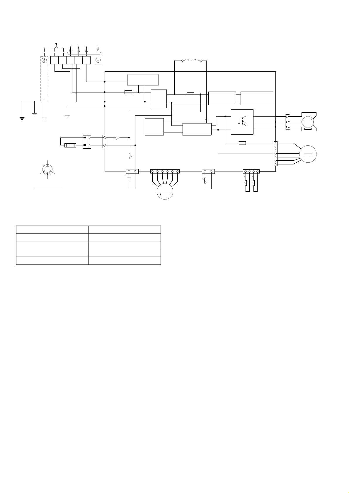
8.2 Outdoor Unit
R
U
Y
L
R
SINGLE PHASE
POWER SUPPLY
N
W/G
CABINET
SIDE
PLATE
THE PARENTHESIZED LETTERS IS
INDICATED ON TERMINAL COVER
Resistance of Compressor Windings
Note: Resistance at 68°F (20°C) of ambient temperature.
GROUNDING TERMINAL
YLW/GRN
YELLOW(YLW)
BLUE
(BLU)
(TRADEMARK)
COMP. TERMINAL
MODEL CU-XE9/12SK
CONNECTION 5RS102XHB21 (Ω)
U-W 1.765
L1 L2
BLK
RED
(RED)
TO INDOO
(BLK) (WHT) (RED)
(BLK)
GRN
HEATER
NIT
(T 3.15A L 250V)
1
VALVE)
REACTOR
GRYGRY
L2-0
(GRAY)
FUSE2
RECTIFICATION
RECTIFICATION
CIRCUIT
CN-TANK
(WHITE)
31 14
t
COMP. TEMP.
SENSOR (THERMISTOR)
ELECTRONIC CONTROLLER
CIRCUIT
SWITCHING POWER
SUPPLY CIRCUIT
Q10
U
P
V
W
N
FUSE1
(T 2.5A L250V)
CN-TH1
(WHITE)
PIPING TEMP.
SENSOR
(THERMISTOR)
tt
(RED) U
(BLUE) V
(YELLOW) W
3
2
1
(RED)
(WHT)
WHT
BLK
1
3
1
3
TERMINAL
BOARD
COM3
RED
(RED)
AC-BLK
(BLACK)
AC-WHT
(WHITE)
WHT
FG01
(GREEN)
CN-HT1
(WHITE)
1
WHT
WHT
RY-HT1
3
ELECTRO-MAGNETIC COIL
(4-WAY VA L V E )
COMMUNICATION
FUSE3
(20A,
250V)
RY-HOT
CIRCUIT
NOISE
FILTER
CIRCUIT
PFC
CIRCUIT
CN-HOT
(BLUE)
13
BLU
CN-EV
(WHITE)
6
ELECTRO-MAGNETIC COIL
(EXPANSION
L2-I
(GRAY)
M
REMARKS
BLU:BLUE GRY:GRAY
BRW:BROWN GRN:GREEN
BLK:BLACK RED:RED
WHT:WHITE YLW :YELLOW
YLW/GRN:YELLOW/GREEN
RED
BLU
YLW
CN-DCFM
(WHITE)
OUTDOOR AIR
TEMP. SENSOR
1
7
(THERMISTOR)
RED
BLK
WHT
BLU
YLW
U-V 1.741
V-W 1.711
33
11
COMPRESSOR
RED
BLU
MS
3
YLW
FAN MOTOR
M
〜
18
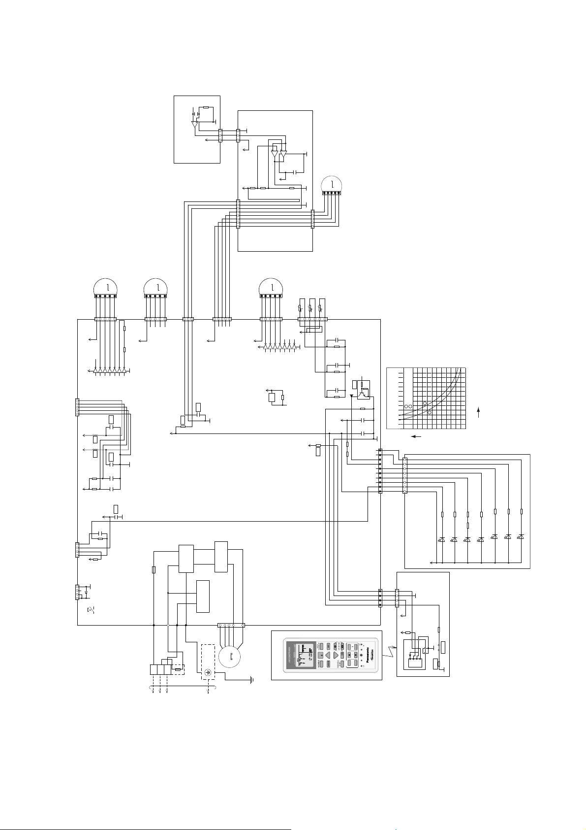
9. Electronic Circuit Diagram
TOOUTDOORUNIT
O
CHEC
K
N
2
TIMER
9.1 Indoor Unit
1%
R408
62.0k
25V
0.1µ
C407
6
5
G2
(WHT)
CN-SENS
3
1
WHT
G2
WHT
WHT
3
1
5V_3
(GREEN)
1%
R401
27.0k
5V_3
1
8
(WHT)
CN-MSSTM
LOUVER MOTOR
WHT
WHT
WHT
WHT
5
(BLU)
CN-STM4
12V
12V
ELECTRONIC
CONTROLLER
CIRCUIT
RECTIFICATION
4
1
7
BLK
WHT
BLU
RED
YLW
M
FAN MOTOR
EVAPORATOR
YLW/GRN
CN-STM1
12V
12V
(WHT)
CN-CNT
12345
12V
5V 5V
(WHT)
CN-RMT
14
5V
(GRN)
CN-CLN
14
UP DOWN
LOUVER MOTOR
M
1
BRW
ORG
RED5YLW
1
(WHT)
16
1514131211
9
1234567
VCC
*L5
*L6
10k
R82
10k
R90
5V
C45
0.01µ
270
R54
10k
R37
D4
(SW01)
AUTO SW
IC402
7
(ECO SENSOR)
5V_6
ELECTRONIC CONTROLLER
CN-SENS
LEFT RIGHT
(OUTER)
PNK
5
R46 1/2W
R47 1/2W
10
IC03
*C57
*C56
50V
C51
1000p
50V
C52
1000p
*C49
LOUVER MOTOR
M
1
PNK
BRW
ORG
RED5YLW
1
68
(YLW)
CN-STM2
12V
68
GND
8
WHT
3
5
(WHT)
CN-MSENS
*R74
5V
FUSE301
T3.15A L2 50V
NOISE FILTER
WHT
WHT
WHT
1
1
(GRN)
CN-STM3
12V
*C40
G2
CIRCUIT
CIRCUIT
COMMUNICATION
AC304(RED)
AC303(WHT)
G301(GRN)
CN-FM
(WHT)
RED
GRN
WHT
BLK AC306(BLK)
GROUNDING
TEMP.FUSE
TERMINAL
215.6˚F/102˚C (3A)
2
3
1
BOARD
TERMINAL
652
7
VCC
5V_3
1%
R402
10.0k
UP DOWN
(INNER)
M
1
BRW
ORG
YLW
RED
1
16
1514131211
9
1234567
VCC
IC06
5V
BZ
BZ1
(MAIN)
REMOTE CONTROLLER
ELECTRONIC
CONTROLLER
(COMPARATOR)
3
IC401
G2
8
4
1
GND
MOTOR
25V
0.1µ
C403
1%
R403
13.0k
5
PIPING TEMP. SENSOR 2
PNK
6
5
5V
10
GND
8
R30
MODE
AIRCONDITI ONER
ECO SENS OR
M
G2
5
1
G2
RED
PNK
ORG
YLW
51
CN-STM
(GREEN)
(THERMISTOR) (20k 3950)
t
5V
BRW
SUCTION TEMP.
SENSOR (THERMISTOR) (15k 3950)
PIPING TEMP. SENSOR 1
(THERMISTOR) (20k 3950)
t
t
1
(RED)
CN-TH
1µ
16V
C28
1%
R63
20.0k
1µ
16V
C27
1%
b
R61
20.0k
1µ
4.7k
10k
16V
C25
*Q09
186
c
1%
R62
15.0k
12V
*R89
e
1M
1%
R58
C1
16V
0.1µ
C3
16V
0.1µ
10
R91 R92
1
CN-DISP(YLW)
Sensor (Therm istor)
WHT
WHT
WHT
WHT
WHT
WHT
WHT
WHT
Pipe Temp. Sensor
112
Characteristics
706050
IntakeAir Temp. Sensor
2
403020
1
8
CN-DISP(WHT)
(DISPLAY)
ELECTRONIC CONTROLLER
5V_
(WHT)
CN-RCV
1
WHT
WHT
WHT
WHT
4
14
5V_
(YLW)
CN-RCV
5V_
RC
ET
RFP
AUTO
COMFORT
N
FF/
OFF/ON
ECONAVI
SET
CANCEL
AIRSWING
AC
TEMP
TEMP
MODE
CLOCK
FANSPEED
FF
123
ON
OFF
TIMER
QUIET
SET CHECK RESE T
POWERFUL/
IC201
ELECTRONIC
CONTROLLER
GND-A
47
R209
1%
1.0k
*R214
123
Vcc
Vout
GND
54
GND-A
GND GND
*R213
122
(50)
104
(40)
86
(30)
68
(20)
Temperature °F (°C)
50
(10)
32
(0)
14
(-10)
0
10
Resistance (kΩ)
R301
R304
LED301
LED304
RFP
(green)
(green)
POWER
R305
R310R302
R303
LED302
LED303
TIMER
(green)
(orange)
ECONAVI
AUTO COMF
680
R306
R307
LED305
LED307
LED306
QUIET
(green)
(orange)
(orange)
POWERFUL
(RECEIVER)
*JP204
GND-A
19
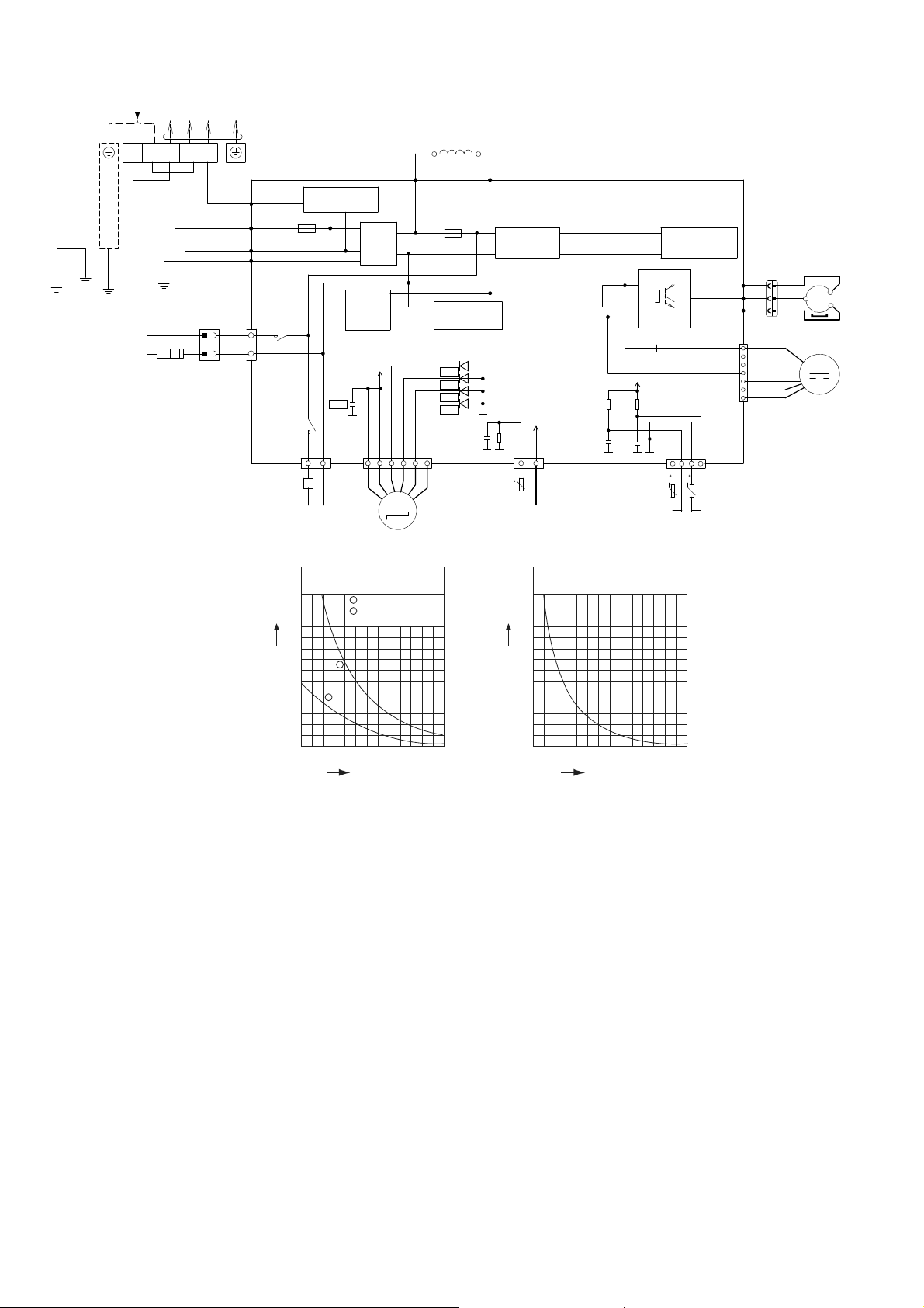
9.2 Outdoor Unit
mperatu
re°F
(°C
T
OINDOORUNIT
Y
LW/GRN
SINGLE PHASE
POWER SUPPLY
(BLK) (WHT)(RED)
CABINET
SIDE
PLATE
M
VALVE)
REACTOR
FUSE2
(T 3.15A L 250V)
RECTIFICATION
CIRCUIT
*D33
*D34
*D35
*D36
CN-EV
1
(WHITE)
104
122
(40)
(50)
GRYGRY
L2-0
(GRAY)
RECTIFICATION
CIRCUIT
G1
C49
1µ
10V
G1 G1
5V
R410
4.99k
CN-TANK
(WHITE)
31 14
t
COMP. TEMP.
SENSOR (THERMISTOR)
(50k, 3950)
Compressor Temp. Sensor
(Thermistor) Characteristics
70
60
50
40
30
Resistance (kΩ)
20
10
0
68
104
140
(20)
(40)
(60)
ELECTRONIC CONTROLLER
Q10
P
N
FUSE1
(T 2.5A L250V)
5V
R101
R100
15.8k
15.0k
1%
1%
C46
C45
1µ
1µ
6.3V
6.3V
G1 G1 G1
PIPING TEMP.
SENSOR
(THERMISTOR)
176
212
248
(80)
(100)
Te
(120)
)
SWITCHING POWER
SUPPLY CIRCUIT
(RED) U
U
(BLUE) V
V
(YELLOW) W
W
CN-DCFM
(WHITE)
CN-TH1
(WHITE)
tt
OUTDOOR AIR
(4.96k, 3800)
284
(140)
TEMP. SENSOR
COMPRESSOR
33
RED
RED
BLU
BLU
MS
3
YLW
〜
YLW
11
RED
1
WHT
7
(THERMISTOR)
(15k, 3950)
BLK
BLU
YLW
FAN MOTOR
M
3
2
1
L1 L2
BLK
(BLK)
(WHT)
(RED)
WHT
BLK
GROUNDING TERMINAL
GRN
YLW/GRN
HEATER
TERMINAL
BOARD
CIRCUIT
PFC
CIRCUIT
G1
6
NOISE
FILTER
13V
L2-I
(GRAY)
COM3
(RED)
RED
AC-BLK
(BLACK)
AC-WHT
(WHITE)
WHT
FG01
(GREEN)
CN-HT1
(WHITE)
1
1
WHT
3
WHT
313
RY-HT1
COMMUNICATION
FUSE3
250V)
(20A,
RY-HOT
CIRCUIT
*C84
CN-HOT
(BLUE)
13
BLU
ELECTRO-MAGNETIC COIL
(4-WAY VALVE)
70
60
50
40
30
Resistance (kΩ)
20
10
0
ELECTRO-MAGNETIC COIL
(EXPANSION
Sensor (Thermistor)
Characteristics
1
Outdoor Air Sensor
2
Outdoor Heat Exchanger
Sensor
1
2
14
(-10)32(0)50(10)68(20)86(30)
Temperature °F (°C)
20

10. Printed Circuit Board
10.1 Indoor Unit
10.1.1 Main Printed Circuit Board
AC303
CN-FM
CN-TH
CN-STM2
CN-RCV
JP1 (Random Auto Restart enable/disable)
10.1.2 Indicator Printed Circuit Board
LED301 LED302 LED304 LED305 LED307 LED306 LED303CN-DISP
CN-STM1
CN-MSENS
CN-STM3
CN-RMT
CN-DISP
CN-STM4
CN-CNT
CN-CLN
21

10.1.3 Receiver Printed Circuit Board
M
CN-RCV
10.1.4 Comparator Printed Circuit Board
CN-MSST
CN-STM
10.1.5 Human Activity Sensor Printed Circuit Board
CN-SENS
CN-SENS
22
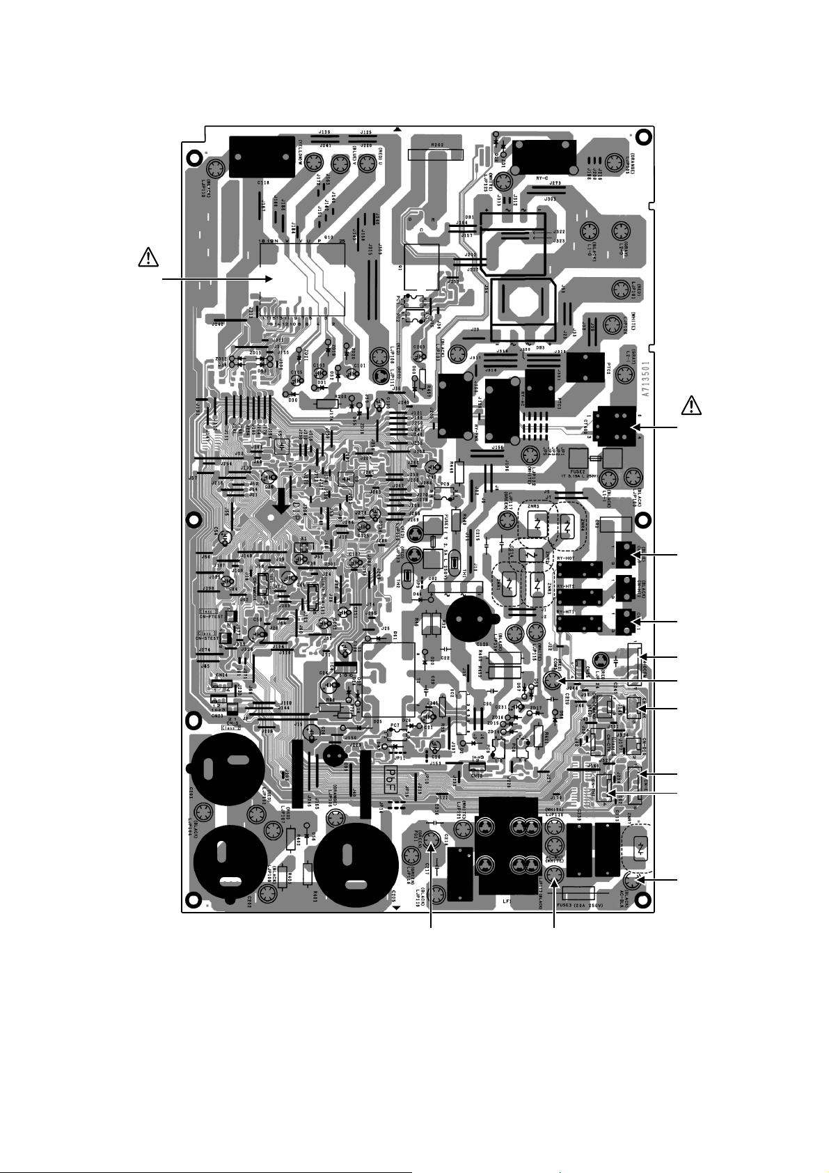
10.2 Outdoor Unit
10.2.1 Main Printed Circuit Board
POWER
TRANSISTOR
(IPM)
CURRENT
TRANSFORMER
(CT)
CN-HOT
CN-HT1
CN-DCFM
COM3
CN-TANK
CN-EV
CN-TH1
AC-BLK
AC-WHTFG01
23
11. Installation Instruction
s
11.1 Select the Best Location
11.1.1 Indoor Unit
Do not install the unit in excessive oil fume area
such as kitchen, workshop and etc.
There should not be any heat source or steam
near the unit.
There should not be any obstacles blocking the air
circulation.
A place where air circulation in the room is good.
A place where drainage can be easily done.
A place where noise prevention is taken into
consideration.
Do not install the unit near the door way.
Ensure the spaces indicated by arrows from the
wall, ceiling, fence or other obstacles.
Mount with the lowest moving parts at least 8ft
(2.4 m) above floor or grade level.
11.1.2 Outdoor Unit
If an awning is built over the unit to prevent direct
sunlight or rain, be careful that heat radiation from
the condenser is not obstructed.
There should not be any animal or plant which
could be affected by hot air discharged.
Keep the spaces indicated by arrows from wall,
ceiling, fence or other obstacles.
Do not place any obstacles which may cause a
short circuit of the discharged air.
If piping length is over the [piping length for
additional gas], additional refrigerant should be
added as shown in the table.
Recommended installation height for outdoor unit
should be above the seasonal snow level.
Be careful not to locate outdoor unit directly under
a roof line where falling snow or ice can cause
damage or dripping water can increase ice
accumulation and defrost cycles.
Min.
Model
XE9SKUA
XE12SKUA
Capacity
(Btu/h)
8700
11500
Piping size
Gas Liquid
3/8"
(9.52 mm)
1/2"
(12.7 mm)
1/4"
(6.35 mm)
Std.
Length
24.6 ft
(7.5 m)
Max.
Elevation
49.2 ft
(15 m)
Piping
Length
9.8 ft
(3 m)
Max.
Piping
Length
65.6 ft
(20 m)
Refrigerant
Example: For XE9SKUA
If the unit is installed at 32.8 ft (10 m) distance, the
quantity of additional refrigerant should be 1.64 oz
(50 g) .... (32.8 - 24.6) ft x 0.2 oz/ft = 1.64 oz.
((10-7.5) m x 20 g/m = 50 g)
Additional
0.2 oz/ft
(20 g/m)
Piping
Length for
add. gas
24.6 ft
(7.5 m)
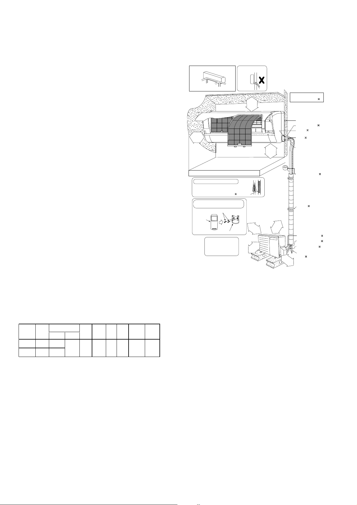
11.1.3 Indoor/Outdoor Unit Installation
Diagram
Piping direc tion Do not bend up
Right
Rear
Right
bottom
131/32"
(50 mm)
or more
Insulation of piping connections
• Carr y out insulation after
checking for gas leaks and
secure with vinyl ta pe.
Attaching the remote control holder
to the wall
Remote control holder fixing screws
Remote
control
(Front side)
Left
Left
Left b ottom
Rear
(Left and right are identical)
Floor / Grade level
3
Remote control holder
It is advisable to avoid more
than 2 blockagedirections.
For better ventilation&
multiple-outdoor installation,
please consult authorized
dealer/specialist.
• This illustration is for
explanation pur poses only.
The indoor unit will actually face
a different way.
drain ho se
Vinyl tape
6
5
Installation parts you
or more
1
/
5
1
0
3
0
1
(
"
)
6
m
e
m
r
o
m
r
o
1
(
3
0
o
r
m
should purchase (
Installation plate 1
Bushing-Sleeve (
Sleeve (
Putty (
(Gum Type Sealer)
Bend t he pipe as
closely on the wall
as possi ble, but be
careful that it doesn’t
break.
Vinyl tape (wide) ( )
• Apply after carrying
out a drainage test.
• To car ry out the
drainage test,
remove the air filter
and pour water into
the he at exchanger.
Saddle (
Connection cable (
Liquid side piping (
Gas side piping (
Additional drain
1
hose (
1
3
/
0
1
6
m
"
m
o
)
r
e
)
e
"
r
m
6
o
1
m
/
m
9
5
r
2
6
o
(
8ft(2.4m)
3
1
5
(
1
/
1
0
6
0
"
o
m
r
m
m
)
o
r
e
"
)
8
/
3
m
m
9
e
3
0
r
o
0
0
m
1
r
(
o
)
)
)
)
)
)
)
)
)
24
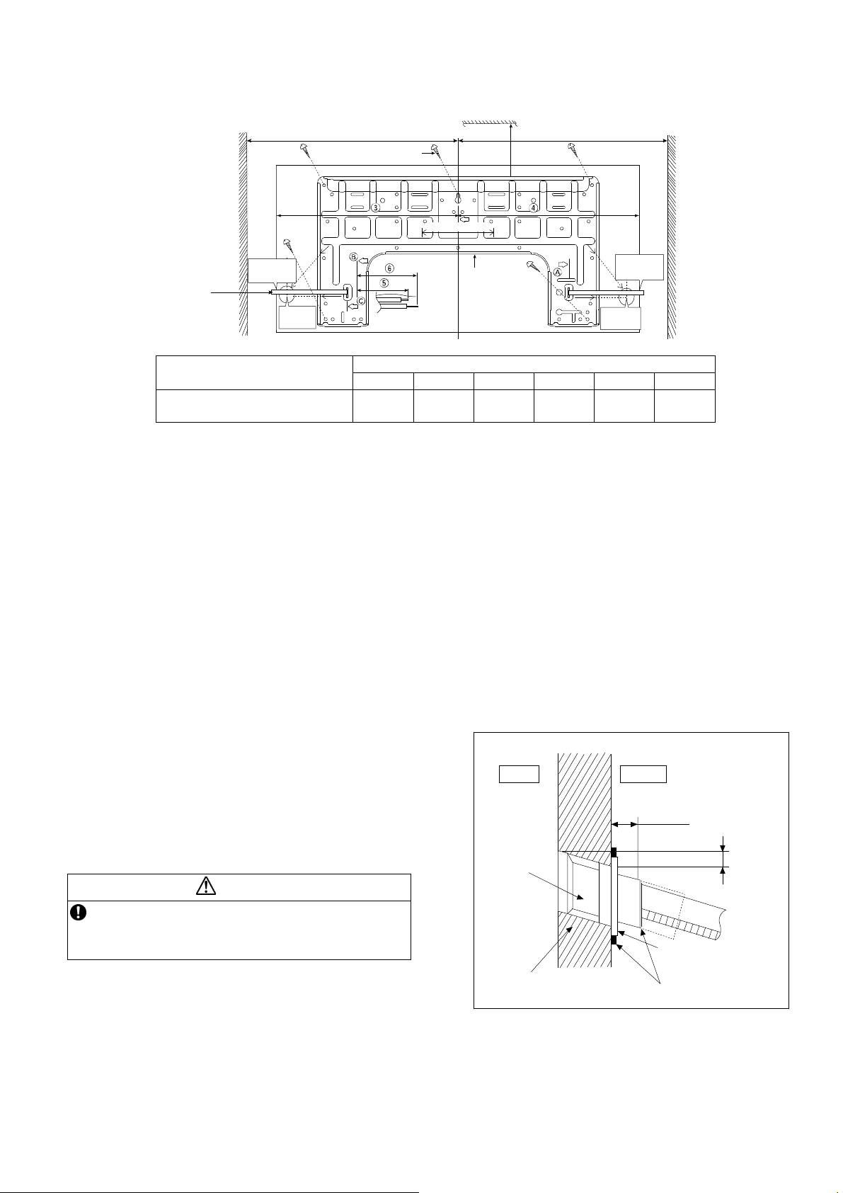
11.2 Indoor Unit
The mounting wall shall be strong and solid enough to prevent it from vibration.
Measuring
Tape
Wall
17
9
/32"
(241.5 mm)
(128 mm)
More than 1
2 screw
51/16" (128 mm)
PIPE HOLE CENTER
DISTANCE
TO PIPE
HOLE
CENTER
1
5
/16"
128 mm
Model
XE9SKUA, XE12SKUA
1 2 3 4 5 6
19-9/32"
(490 mm)
3-7/32"
(82 mm)
The center of installation plate should be at more than 1 at right and left of the wall.
The distance from installation plate edge to ceiling should more than 2.
From installation plate left edge to unit’s left side is 3.
From installation plate right edge to unit’s right is 4.
B : For left side piping, piping connection for liquid should be about 5 from this line.
○
: For left side piping, piping connection for gas should be about 6 from this line.
1 Mount the installation plate on the wall with 5 screws or more (at least 5 screws).
(If mounting the unit on the concrete wall, consider using anchor bolts.)
o Always mount the installation plate horizontally by aligning the marking-off line with the thread and using
a level gauge.
2 Drill the piping plate hole with ø2-3/4" (ø70 mm) hole-core drill.
o Line according to the left and right side of the installation plate. The meeting point of the extended line is
the center of the hole. Another method is by putting measuring tape at position as shown in the diagram
above. The hole center is obtained by measuring the distance namely 5-1/16" (128 mm) for left and right
hole respectively.
o Drill the piping hole at either the right or the left and the hole should be slightly slanting to the outdoor
side.
11.2.1 To Drill a Hole in the Wall and
Install a Sleeve of Piping
1 Insert the piping sleeve to the hole.
2 Fix the bushing to the sleeve.
3 Cut the sleeve until it extrudes about 19/32"
(15 mm) from the wall.
When the wall is hollow, please be sure to use the
sleeve for tube assembly to prevent dangers
caused by mice biting the connection cable.
4 Finish by sealing the sleeve with putty or
caulking compound at the final stage.
CAUTION
Wall
More
than 2
Installation
plate 1
17-9/32"
(439 mm)
ø2
through hole
Dimension
Indoor
Sleeve
for tube
assembly
3
/4" (ø70 mm)
More than 1
DISTANCE TO
PIPE HOLE
CENTER 128 mm
PIPE HOLE
CENTER
17"
(432 mm)
Wall
51/16"
(128 mm)
1-11/16"
(43 mm)
Wall
17
9
/32"
(241.5 mm)
3-3/4"
(95 mm)
Outdoor
19
/32"(15mm)
Approx.7/32"-9/32"
(5-7 mm)
Bushing for tube
assembly
Putty or caulking compound
25

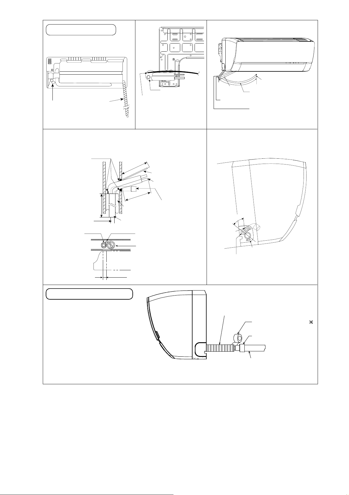
11.2.2 Indoor Unit Installation
•
Do not turn over the unit
without it’s shock absorber
p
Piping
u
l
l
during pulling out the piping.
o
u
t
It may cause intake grille
t
h
e
p
i
p
i
damage.
n
g
Piping
Use shock absorber
during pulling out
l
o
u
t
t
h
e
p
the piping to protect
the intake grille from
i
p
i
damage.
n
g
p
u
l
PUSH PUSH
Intake grille
11.2.2.1 For the right rear piping
Step-1
Step-2
Step-3
Step-4
Pull out the Indoor piping
Install the Indoor Unit
Secure the Indoor Unit
Insert the connection cable
11.2.2.2 For the right bottom piping
Step-1
Step-2
Step-3
Step-4
Pull out the Indoor piping
Install the Indoor Unit
Insert the connection cable
Secure the Indoor Unit
11.2.2.3 For the embedded piping
Step-1
Step-2
Step-3
Step-4
Step-5
Step-6
Step-7
Step-8
Replace the drain hose
Bend the embedded piping
• Use a spring bender or equivalent to bend the piping so that the
piping is not crushed.
Pull the connection cable into Indoor Unit
• The inside and outside connection cable can be connected without
removing the front grille.
Cut and flare the embedded piping
• When determining the dimensions of the piping, slide the unit all the
way to the left on the installation plate.
• Refer to the section “Cutting and flaring the piping”.
Install the Indoor Unit
Connect the piping
• Please refer to “Connecting the piping” column in outdoor unit
section. (Below steps are done after connecting the outdoor piping
and gas-leakage confirmation.)
Insulate and finish the piping
• Pl e ase r efe r t o “Insulation of pi ping connection” column as
mentioned in indoor/outdoor unit installation.
Secure the Indoor Unit
PUSH PUSH
Shock absorber
Right Rear piping
Tape it with
piping in a position as
mentioned in
Fig. below.
Piping
Drain
hose
Cover for the
bottom piping
Cover for the
bottom piping
Cover
for the
left
piping
Cover for piping
How to keep the cover
In case the cover is cut, keep the cover at the rear
of chassis as shown in the illustration for future
reinstallation.
(Left and 2 bottom covers for piping.)
Right and Right Bottom piping
Tape it with piping in a
position as mentioned in
Fig. below.
Piping
Drain hose
Cover for
the right
piping
Cover for the
bottom pipin g
Install the indoor unit
Hook the indoor unit onto the upper portion
of installation plate. (Engage the indoor u nit
with the upper edge of the installation plate).
Ensure the hooks are properly seated on
the installation plate by m oving it in left and
right.
Indoor unit
Cover for
the left
piping
Hooks at
installation
plate
Sleeve for
piping hole
Piping
Drain hose
Secure the Indoor Unit
1. Press the lower left and right side of the
unit against the installation plate until hooks
engages with their slot (sound click).
Unit’s
hook
To take out the unit, push the marking
at the bottom unit, and pull it slightly towards
you to disengage the hooks from the unit.
m
a
r
i
n
g
k
Installation
plate
Insert the connection cable
2
A
3
b
/
4
o
(
"
7
u
0
-
t
-
3
8
5
0
/
3
m
2
"
m
)
Guide
surface
Connection
cable
Connection cable
Gas side
piping
Liquid side
piping
Drain hose
(This can be used for left rear piping and bottom
piping also.)
26
Replace the drain hose
Rear view for left piping installation
Drain cap
Drain hose
Drain hose
Connection cable
Adjust the piping
slightly downwards.
Piping
Drain hose
Connection cable
9
More than 45
(1150 mm)
Sleeve for piping hole
/32"
How to pull the piping and drain hose out, in case
•
of embedded piping
Apply putty or
caulking material
to seal the wall
opening.
More than
PVC tube for drain
hose (VP-20)
PVC tube
for drain
hose
Drain hose adapter
Join indoor drain hose to 3/4"
•
9
"
16
/
27
(700 mm)
7
.
M
PVC tube for drain hose (VP-30)
Indoor unit
27
/32"(72mm)
2
n
a
h
t
re
o
"
2
)
3
/
9
m
m
5
4
0
5
1
(1
r
o
M
"
2
1
/
8
1
PVC tube (VP-65) for piping
and connection cable
a
h
t
e
0
7
4
(
Cable
Piping
Connection
cable
Piping
n
m
m
usage
)
Drain hose
from main unit
(20 mm) nominal PVC pipe size
by using drain hose adapter
7
when necessary.
How to insert the connection cable
•
and drain hose in the case of left
piping.
°
5
4
Drain
hose
Cable
Piping
(For right piping, follow the same
procedure)
Indoor unit
drain hose
Close join by Vinyl Tape ( )
Remarks :
Make sure indoor unit drain hose
& 3/4" (20 mm) nominal PVC pipe
are fully inserted to drain hose
adapter
7
.
Drain hose adapter
3/4" (20 mm) nominal PVC pipe
- Install incline downward more than 1°
- Apply PVC glue at the join.
7
27
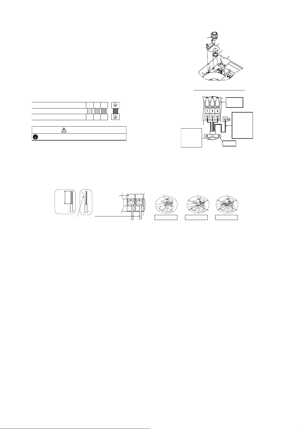
11.2.3 Connect the Cable to the Indoor Unit
restrip
pin
g
1 The inside and outside connection cable can
be connected without removing the front grille.
2 Unscrew the conduit cover and fix the conduit
connector to conduit cover with lock nut, then
secure it against chassis.
3 Connection cable between indoor unit and
outdoor unit should be UL listed or CSA
approved 4 conductor wires minimum AWG16
in accordance with local electric codes.
o Ensure the colour of wires of outdoor unit
and terminal number are the same as the
indoor's respectively.
Terminals on the indoor unit 1 2 3
Colour of wires (connection cable)
Terminals on the outdoor unit 1 2 3
WARNING
This equipment must be properly earthed.
o Earth lead wire shall be Yellow/Green
(Y/G) in colour and shall be longer than
other lead wires as shown in the figure
for electrical safety in case of slipping.
Conduit
Connector
Conduit Cover
Lock Nut
Chassis
Rear Side of Indoor Unit
Terminal
Board
Earth wire
longer than
others
AC wi res
Holder
for safety
reason
Indoor and
outdoor
connection
cable
11.2.3.1 Wire Stripping and Connecting Requirement
Wi
(10 ± 1 mm)
13/32" ± 1/16"
No loose strand
when inserted
Indoor/outdoor
connecting
terminal board
7
/32" (5 mm)
or more
(gap between wires)
Conductor
fully inser ted
ACCEPT
Conductor
over inserted
PROHIBITED
Conductor not
fully inser ted
PROHIBITED
28

11.3 Outdoor Unit
B
S
11.3.1 Install the Outdoor Unit
After selecting the best location, start installation according to Indoor/Outdoor Unit Installation Diagram.
1 Fix the unit on concrete or rigid frame firmly and horizontally with a bolt nut ø13/32" (ø10 mm).
2 When installing at roof, please consider strong wind and earthquake.
Please fasten the installation stand firmly with bolt or nails.
11.3.2 Connect the Piping
11.3.2.1 Connecting the Piping to
Indoor
Please make flare after inserting flare nut (locate at
joint portion, of tube assembly) onto the copper pipe.
(In case of using long piping)
Connect the piping
Align the center of piping and sufficiently tighten
the flare nut with fingers.
Further tighten the flare nut with torque wrench in
specified torque as stated in the table.
A
C
D
Model A B C D
XE9SKUA,
XE12SKUA
24-1/8"
(613 mm)
5-5/32"
(131 mm)
5/8"
(16 mm)
Do not over tighten, over tightening may cause gas leakage
Piping size Torque
1/4" (6.35 mm) 13.3 Ibf.ft [18N•m (1.8 kgf.m)]
3/8" (9.52 mm) 31.0 Ibf.ft [42 N•m (4.3 kgf.m)]
1/2" (12.7 mm) 40.6 Ibf.ft [55 N•m (5.6 kgf.m)]
5/8" (15.88 mm) 47.9 Ibf.ft [65 N•m (6.6 kgf.m)]
3/4" (19.05 mm) 73.8 Ibf.ft [100 N•m (10.2 kgf.m)]
14-3/16"
(360.5 mm)
11.3.2.2 Connecting the Piping to
Outdoor
Decide piping length and then cut by using pipe cutter.
Remove burrs from cut edge.
Make flare after inserting the flare nut (located at valve)
onto the copper pipe.
Align center of piping to valve and then tighten with
torque wrench to the specified torque as stated in the
table.
panner
or Wrench
11.3.2.3 Gas leak checking
Pressure test to system to 400 PSIG with dry nitrogen, in stages. Thoroughly leak check the system.
If the pressure holds, release the nitrogen and proceed to section 11.3.3.
Torque
wrench
29
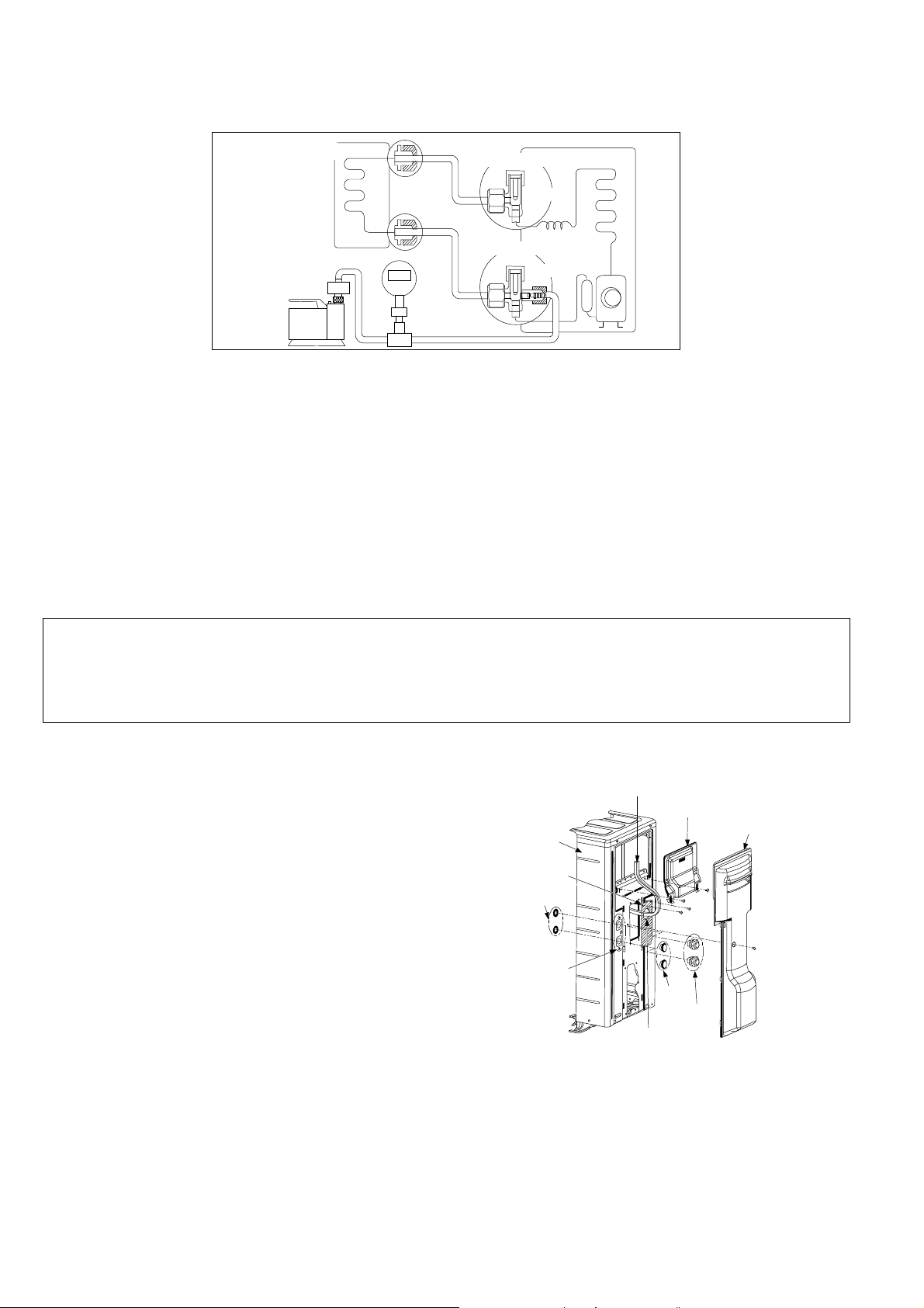
11.3.3 Evacuation of the Equipment
L
e
c
r
e
Ope
e
WHEN INSTALLING AN AIR CONDITIONER, BE SURE TO EVACUATE THE AIR INSIDE THE INDOOR UNIT AND
PIPES in the following procedure.
Indoor unit
Vac uu m
pump
1 Connect a charging hose with a push pin to the Low side of a charging set and the service port of the 3-way
valve.
2 Connect the micron gauge between vacuum pump and service port of outdoor units.
3 Turn on the power switch of the vacuum pump and make sure that connect digital micron gauge and to pull
down to a value of 500 microns.
4 To make sure micron gauge a value 500 microns and close the low side valve of the charging set and turn off
the vacuum pump.
5 Disconnect the vacuum pump house from the service port of the 3-way valve.
6 Tighten the service port caps of the 3-way valve at a torque of 13.3 Ibf.ft (18 N•m) with a torque wrench.
7 Remove the valve caps of both of the 2-way valve and 3-way valve. Position both of the valves to “Open”
using a hexagonal wrench (5/32" (4 mm)).
8 Mount valve caps onto the 2-way valve and the 3-way valve.
o Be sure to check for gas leakage.
If micron gauge value does not descend 500 microns, take the following measures:
- If the leak stops when the piping connections are tightened further, continue working from step .
- If the leak does not stop when the connections are retightened, repair location of leak.
- Do not release refrigerant during piping work for installation and reinstallation.
- Be careful with the liquid refrigerant, it may cause frostbite.
Liquid side
Gas side
Tw o - w a y v a lv e
Close
Three-way valve
Close
Outdoor unit
11.3.4 Connect the Cable to the Outdoor Unit
1 Remove control board cover (Resin and
Metal).
2 Remove particular plate.
3 Remove plugs.
4 Fix the conduit connectors to the knockout
holes with lock-nuts, then secure them against
the side panel.
5 All wires pass through conduits & particular
plate’s opening hole.
6 Connecting wire between indoor unit and
outdoor unit should be UL listed or CSA
approved 4 conductor wires minimum AWG16
in accordance with local electric codes.
7 Wire connection to the power supply
(208/230V 60Hz) through circuit breaker.
o Connect the UL listed or CSA approved
wires minimum AWG14 to the terminal
board, and connect the other end of the
wires to ELCB/ GFCI.
8 Connect the power supply cord and
connecting wire between indoor unit and
outdoor unit according to the diagram below.
ting wi
s
Control Board
Cover (Metal)
Plugs
Connectors
Particular Plate
ninghol
Control Board
Cover (Resin)
Fron t
Panel
Particular
Plate
ock Nuts
Knockout
Holes
Conn
30
 Loading...