

Panasonic cu-pa7dkd, cu-pc7dkd, cs-pa9dkd, cu-pa9dkd, cs-pc9dkd Service Manual
...
CS/CU-PA7DKD
CS/CU-PC7DKD
CS/CU-PA9DKD
CS/CU-PC9DKD
Room Air Conditioners
WARNING
This service information is designed for experienced repair technicians only and is not designed for use by the general public.
It does not contain warnings or cautions to advise non-techical individuals of potential dangers in attempting to service a product.
Products powered by electricity should be serviced or repaired only by experienced professional technicians. Any attempt to service
or repair the product or products dealt with in this service information by anyone else could result in serious injury or death.
1 Features 2
2 Functions 3
3 Product Specifications 6
4 Dimensions 14
5 Refrigeration Cycle Diagram 16
6 Block Diagram 17
7 Wiring Diagram 19
8 Operation Details 21
9
Installation
35
10 2-way,3-way Valve
11
Disassembly of The Parts
12 Troubleshooting Guide
13 Technical Data
14 Exploded View
15 Replacement Parts List
16 Exploded View
17 Replacement Parts List
18 Electronic Circuit Diagram
CONTENTS
Page Page
Order No. GMAC0504036C3
Guangzhou Matsushita Air Conditioner Co., Ltd.
(GMAC) All rights reserved. Unauthorized copying
and distribution is violation of law.
C
R
49
56
59
61
64
65
66
67
68
------------------------------------------------------
--------------------------------------------------------
------------------------------------------
-----------------------------------------------------
-----------------------------------
--------------------------------------------------
-------------------------------------------------
-----------------------------------------------
---------------------------------------------------
-----------------------------------------------------
--------------------------------------
----------------------------------------
--------------------------------------------------
--------------------------------------------------
-----------------------------------------
--------------------------------------------------
-----------------------------------------
--------------------------------------
R
OFF
MODE TEMP
OFF/ON
ON
CANCEL SET
STD
TIMER
FANSPEED
AIRSWING

2
1 Features
High Efficiency
Air Quality Indicator
Comfort Environment
Air filter with function to reduce dust and smoke
Auto Restart Control
Automatically restart after power failure
12-hour Timer Setting
CS-PA7DKD / CU-PA7DKD / CS-PC7DKD / CU-PC7DKD
Operation START/STOP
Operation Mode Selection
Automatic Operation
Heating Mode Operation
(For PA7DKD,PA9DKD)
Cooling Mode Operation
Soft Dry Mode Operation
Air Circulation Mode Operation
(For PC7DKD,PC9DKD)
Mode
Indoor Fan Speed Selection
Low Speed
Medium Speed
High Speed
Automatic Speed
Airflow Direction Control
Horizontal Airflow Direction Control
-Auto Control
-Manual Control
Vertical Airflow Direction Manual Control
Room Temperature Setting
Temperature Setting(16 to 30 )
Auto Operation
Timer Operation Selection
Stop/Start Operation Control
(set the ON/OFF Timer hourly later)
Set /Cancel Timer Operation
Set timer/Cancel the set timer
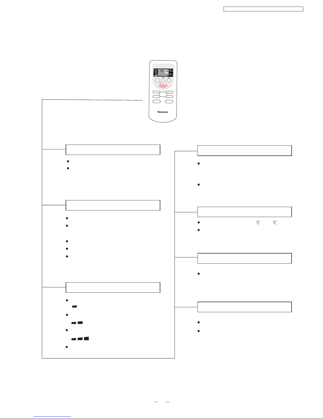
2 Functions
Remote Control
3
OFF/ON
MODE
FAN
SPEED
Air
SWING
TEMP
TIMER
OFF/ON
TIMER
SET/
CANCEL
OFF
MODE TEMP
OFF/ON
ON
CANCEL SET
STD
TIMER
FANSPEED
AIRSWING
Turn on/off the air conditionor
When stop the operation by pressing
OFF/ON button,the cursor key points
to OFF.
By pressing SET button for 5seconds
continuously to switch to set the sensor
sensitivity.
CS-PA7DKD / CU-PA7DKD / CS-PC7DKD / CU-PC7DKD
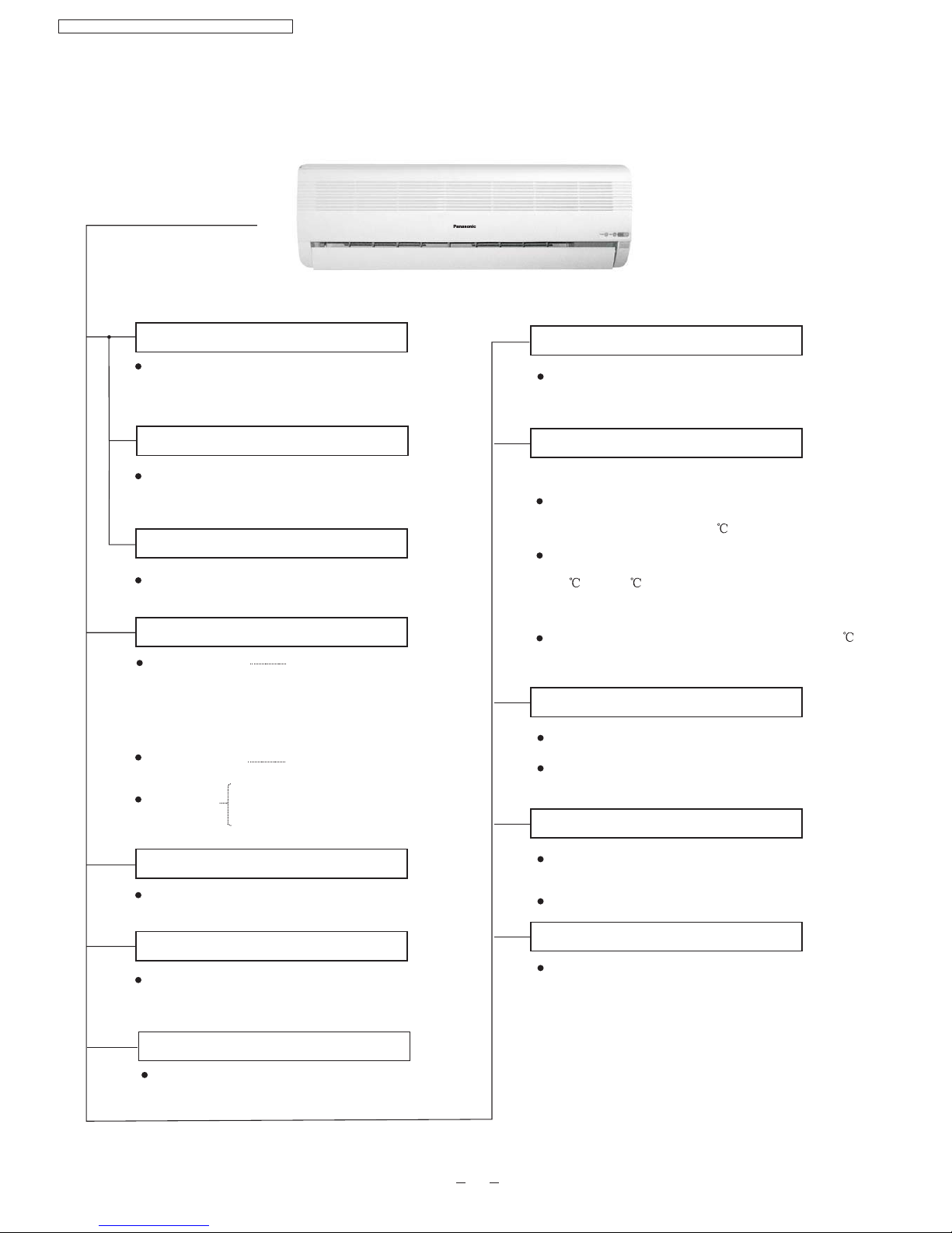
Indoor Unit
Demonstration Mode
When the remote control cannot be used or
for repairing and testing ,please use this
button.
Power Switch ON/OFF
Signal Receiving Sound Control
Keep pressing this button for 10seconds to turn
on or turn off the signal receiving sound.
Operation Indication Lamps
Power (green)
Timer(orange)
Lights up in operation;
Blinks during Test
Run operation and
determining Auto
Operation mode
Timer in operation
Operation Mode
Cooling/Heating/Soft Dry /Auto Operation
/ Air circulation
Time Delay Safety Control
The unit will restart operation in 3-4
minutes after each pause.
7-Minutes Time Save Control
7-minutes automatic restarting at Cooling
Operation
National
4
Keep pressing this button for 15seconds to start
or end the Demonstration Mode.
Auto Switch
Button
Air quality
Green
Orange
Red
Anti-freezing Control for the Evaporator
Cooling or Soft Dry Operation
Warm Booting Control
Indoor fan starts running when temperature
of evaporator reaches 30 or above.
When temperature of evaporator is between
30 and 34 ,indoor fan will run at Super Low
or Low speed.
When temperature of evaporator reaches 34 ,
Warm Booting Operation ends.
High,Med,Low
Auto Fan Speed
Indoor Fan Speed Control
Automatic Airflow Direction Control
The louver automatically swings up and down
Airflow Direction Manual Control
Airflow Direction Control
Delayed On-timer Control
For cooling or soft dry mode, the unit
starts 15 minutes before the set time with
the remote control, but for heating mode
30 minutes before the set time.
(For PA7DKD, PA9DKD only)
CS-PA7DKD / CU-PA7DKD / CS-PC7DKD / CU-PC7DKD
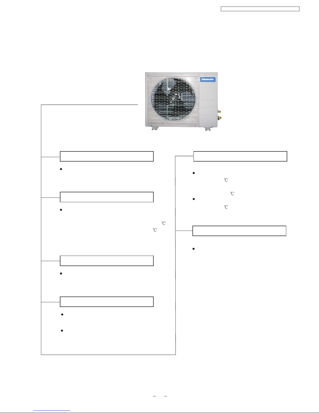
Outdoor Unit
5
Panasonic
Anti-reverse Protection
To protect the compressor from reverse
rotation when power off suddenly.
Overload Protector
The 2-step Overload Protector is to protect
the compressor when
1)Temperature of compressor reaches 150
(PA7DKD,PC7DKD,PA9DKD) or
2)High temperature or current enters into the
compressor
145
(PC9DKD)
60-seconds Test Operation Control
Once the compressor is activated, it does not
stop for 60 seconds. It stops immediately with
remote control ON/OFF button.
Anti-freezing operation for outdoor unit(during
Heating Mode Operation only)
Temperature of the condenser is tested by TRS.
(For PA7DKD,PA9DKD only)
Deicing Control
Overload Protection Control
When the temperature of evaporator
reaches 51 ,outdoor fan stops,and will
restart when the temperature of evaporator
declines to 49 .
When the temperature of evaporator
reaches 65 ,compressor will stop.
4-way Valve Control
If the unit is stopped during Heating
Operation,the 4-way valve will remain in
heating mode operation for 5 minutes.
CS-PA7DKD / CU-PA7DKD / CS-PC7DKD / CU-PC7DKD
(For PA7DKD,PA9DKD only)
(Only for PA7DKD,PA9DKD)
6
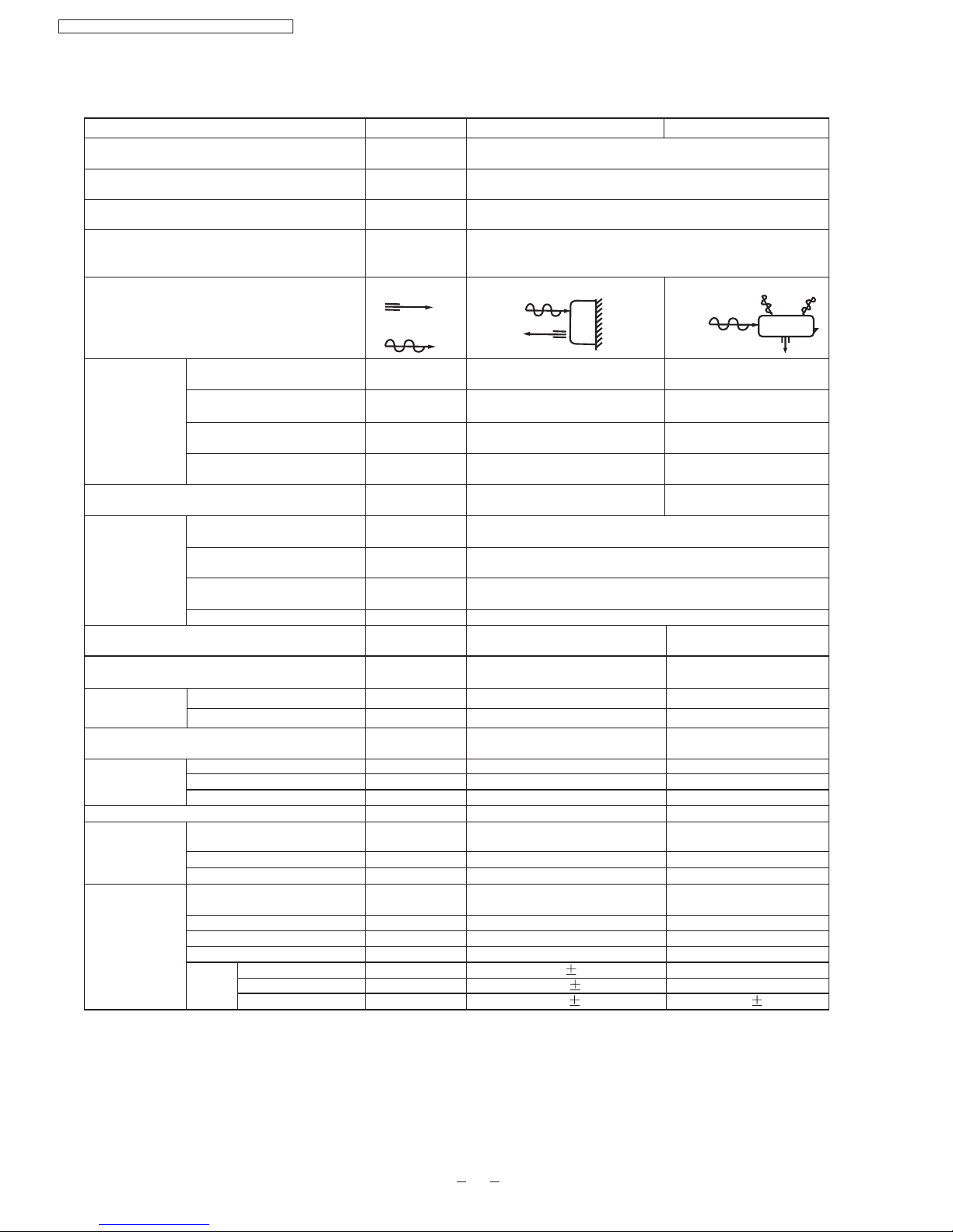
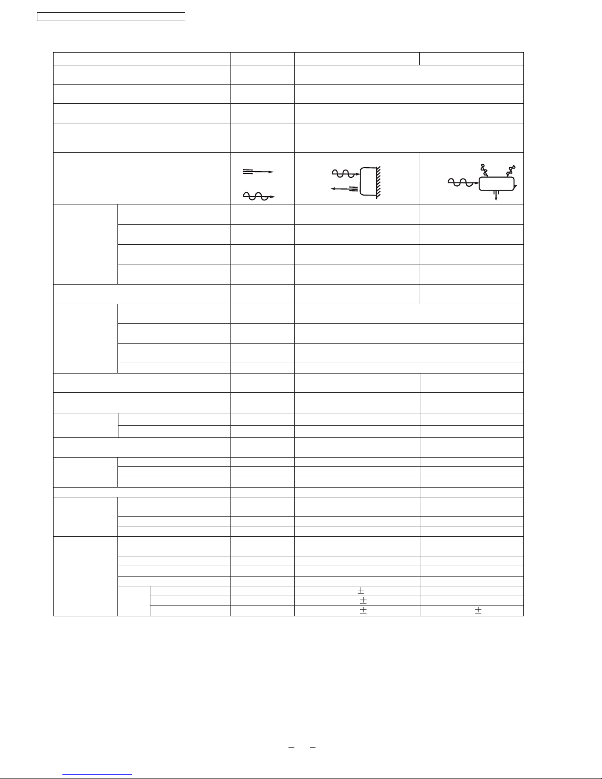
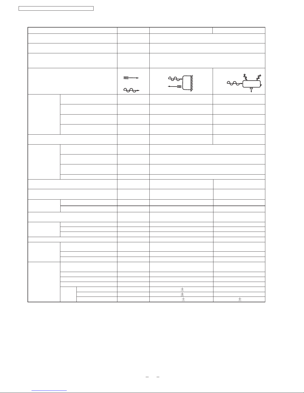
3 Product Specifications
Cooling Capacity
Heating Capacity
Moisture Removal
Power Source
Airflow Method
Air Circulation
Indoor Air (low)
Indoor Air (medium)
Indoor Air (high)
Outdoor Air
Noise Level
Electrical
Data
Piping Connection Port(Flare piping)
Piping Size(Flare piping)
Drain Hose
Power Supply Cord Length
(Number of core-wire)
Dimensions
Net Weight
Compressor
Air Circulation
Unit
kW
kW
L/h
Phase
V
Cycle
OUTLET
INTAKE
m /min
3
m /min
3
m /min
3
m /min
3
dB(A)
W
A
W/W
A
Input
Running Current
EER/COP
Starting Current
Inner Diameter
Length
Height
Width
Depth
Type
Motor Type
Rated output
type
Motor type
Fan
Speed
Low
Med
High
Rated Output
Input
Inch
Inch
Inch
Inch
mm
m
mm
mm
mm
kg
W
W
W
rpm
rpm
rpm
CS-PA7DKD CU-PA7DKD
2.10
2.30
1.2
Single
220
50
SIDE VIEW
TOP VIEW
7.40
8.66
9.50
-
-
-
-
Cooling:high47
Heating:high48
Cooling:high37,Low29
Heating:high37,Low29
Cooling:695
Heating:620
Cooling:3.40
Heating:3.00
Cooling:3.02
Heating:3.71
18
G:half union3/8"
L:half union1/4"
G:gas side3/8"
L:liquid side1/4"
G:3-way valve3/8"
L:2-way valve1/4"
G:gas side3/8"
L:liquid side1/4"
-
-
-
-
-
-
-
m
14
0.5
1.3
3 core-wire/1.0mm
2
250
770
205
7.5
530
650
230
23
-
-
-
Cross-flow fan
Induction(4 pole)
-
13
Rotary(1 cylinder)
Rolling piston type
Induction(2 pole)
600
Propeller fan
Induction(6 pole)
-
28
-
880 60
1030 60
1130 50
-
800 60
-
CS-PA7DKD / CU-PA7DKD / CS-PC7DKD / CU-PC7DKD
7
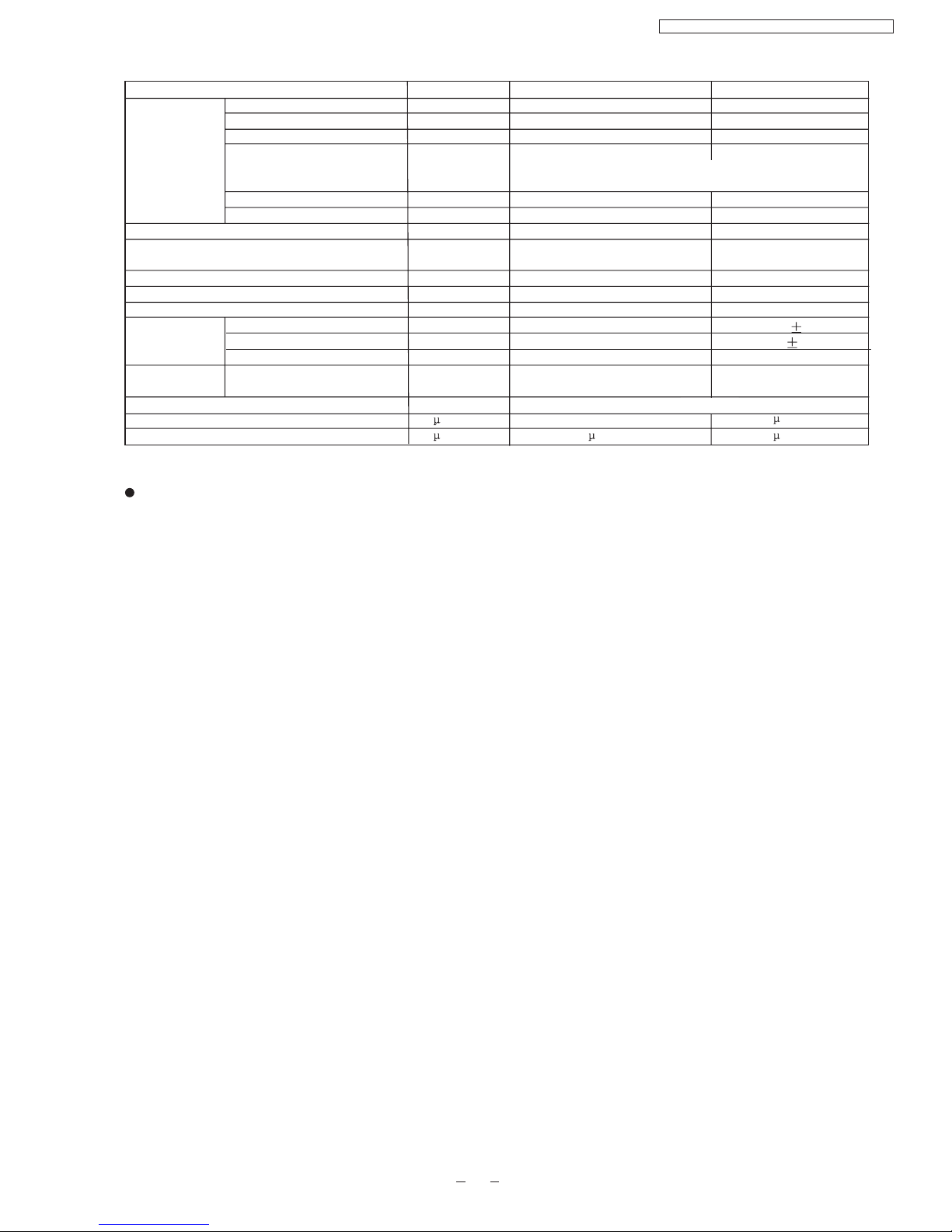
Heat
Exchanger
Description
Tube Material
Fin Type
FPI
Refrigerant Control Device
Refrigeration Oil
Refrigerant (R-22)
Thermostat
Protection Device
Capillary
Air Filter
Refrigerant Circulation Control Device
Compressor Capacitor
Fan Motor Capacitor
Unit CS-PA7DKD CU-PA7DKD
Length
Circulation
Inner Diameter
mm
(c.c)
g
mm
L/min
mm
F,V
F,V
Evaporator
Copper
Slot type
(Plate fin configuration,forced draft)
2x12
1X24
Condenser
Copper
Corrugation type
18
610x252x25.4
-
-
-
-
-
-
-
Electronic Control
P.P. Honeycomb
-
17
Capillary Tube
530(*)
-
O.L.P.(230V,30A)
655 20
9.5 0.2
1.4
F,2.0 400V
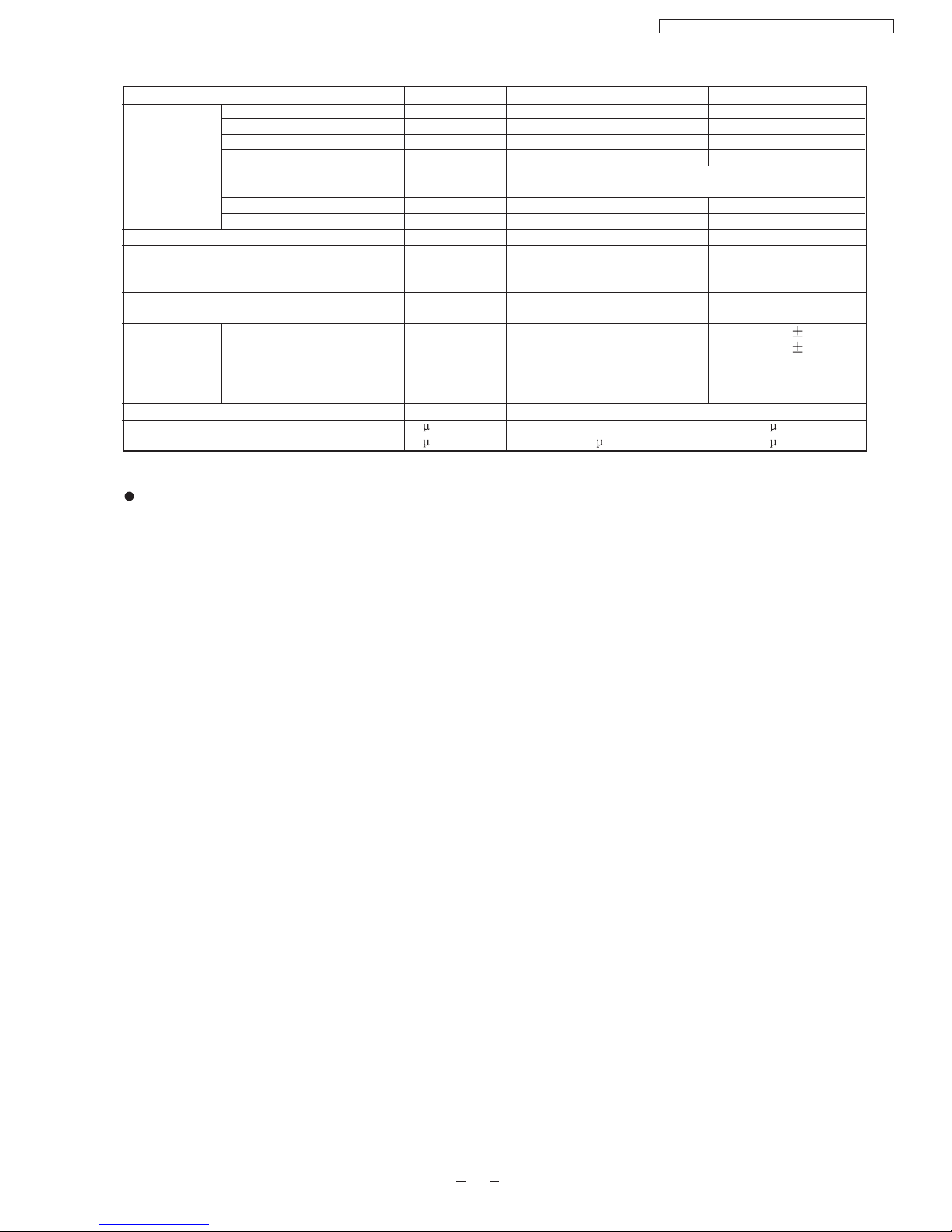
Specifications are subject to change without notice for further improvement.
F , 400V
Dimensions
Rows/Stage
Capillary
F,
20 370V
1.5
269.1x504x18.19
SUNISO 4GDID or ATMOS
M60 or ATMOS 56M
* 60g for air purging is not included.
CS-PA7DKD / CU-PA7DKD / CS-PC7DKD / CU-PC7DKD
Cooling Capacity
Heating Capacity
Moisture Removal
Power Source
Airflow Method
Air Circulation
Indoor Air (low)
Indoor Air (medium)
Indoor Air (high)
Outdoor Air
Noise Level
Electrical
Data
Piping Connection Port(Flare piping)
Piping Size(Flare piping)
Drain Hose
Power Supply Cord Length
(Number of core-wire)
Dimensions
Net Weight
Compressor
Air Circulation
Unit
kW
kW
L/h
Phase
V
Cycle
OUTLET
INTAKE
m /min
3
m /min
3
m /min
3
m /min
3
dB(A)
W
A
W/W
A
Input
Running Current
EER/COP
Starting Current
Inner Diameter
Length
Height
Width
Depth
Type
Motor Type
Rated output
type
Motor type
Fan
Speed
Low
Med
High
Rated Output
Input
Inch
Inch
Inch
Inch
mm
m
mm
mm
mm
kg
W
W
W
rpm
rpm
rpm
CS-PA9DKD CU-PA9DKD
2.60-2.65
3.00-3.05
1.40
Single
220/230
50
SIDE VIEW
TOP VIEW
7.72
8.54
10.10
-
-
-
-
Cooling:high47
Heating:high48
Cooling:high38,Low29
Heating:high38,Low29
Cooling:830-850
Heating:790-820
Cooling:3.90-3.80
Heating:3.65-3.65
Cooling:3.13-3.12
Heating:3.80-3.72
16
G:half union3/8"
L:half union1/4"
G:gas side3/8"
L:liquid side1/4"
G:3-way valve3/8"
L:2-way valve1/4"
G:gas side3/8"
L:liquid side1/4"
-
-
-
-
-
-
-
m
3 core-wire/1.0mm
2
250
770
205
7.5
530
650
230
27
-
-
-
Cross-flow fan
Induction(4 pole)
-
13
Rotary(1 cylinder)
Rolling piston type
Induction(2 pole)
700
Propeller fan
Induction(6 pole)
-
28
-
940 60
1090 60
1230 60
-
800 60
-
CS-PA7DKD / CU-PA7DKD / CS-PC7DKD / CU-PC7DKD
8
14
0.5
1.3
Heat
Exchanger
Description
Tube Material
Fin Type
FPI
Refrigerant Control Device
Refrigeration Oil
Refrigerant (R-22)
Thermostat
Protection Device
Capillary
Air Filter
Refrigerant Circulation Control Device
Compressor Capacitor
Fan Motor Capacitor
Unit CS-PA9DKD CU-PA9DKD
Length
Circulation
Inner Diameter
mm
(c.c)
g
mm
L/min
mm
F,V
F,V
Evaporator
Copper
Slot type
(Plate fin configuration,forced draft)
2x12
2X24
Condenser
Copper
Corrugation type
18
610x252x25.4
-
-
-
-
-
-
-
Electronic Control
P.P. Honeycomb
-
17
Capillary Tube
860(*)
-
O.L.P.(230V,37A)
609 10
10.0 0.2
1.4
F,2.0 400V
Specifications are subject to change without notice for further improvement.
F , 400V
Dimensions
Rows/Stage
Capillary
F,30 370V
1.5
X504x36.38
SUNISO 4GDID or ATMOS
M60 or ATMOS 56M
569.1
540.5
* 60g for air purging is not included.
495 20
9.0 0.2
1.3
CS-PA7DKD / CU-PA7DKD / CS-PC7DKD / CU-PC7DKD
9
Cooling Capacity
Moisture Removal
Power Source
Airflow Method
Air Circulation
Indoor Air (low)
Indoor Air (medium)
Indoor Air (high)
Outdoor Air
Noise Level
Electrical
Data
Piping Connection Port(Flare piping)
Piping Size(Flare piping)
Drain Hose
Power Supply Cord Length
(Number of core-wire)
Dimensions
Net Weight
Compressor
Air Circulation
Unit
kW
L/h
Phase
V
Cycle
OUTLET
INTAKE
m /min
3
m /min
3
m /min
3
m /min
3
dB(A)
W
A
W/W
A
Input
Running Current
EER
Starting Current
Inner Diameter
Length
Height
Width
Depth
Type
Motor Type
Rated Output
Type
Motor Type
Fan
Speed
Low
Med
High
Rated Output
Input
Inch
inch
Inch
inch
mm
m
mm
mm
mm
kg
W
W
W
rpm
CS-PC7DKD CU-PC7DKD
2.10
1.20
Single
220
50
SIDE VIEW
TOP VIEW
4.9
5.7
6.8
-
-
-
-
High47
High36,Low28
680
3.20
3.09
15
G:half union3/8"
L:half union1/4"
G:gas side3/8"
L:liquid side1/4"
G:3-way valve3/8"
L:2-way valve1/4"
G:gas side3/8"
L:liquid side1/4"
-
-
-
-
-
-
-
m
3 core-wire/1.0mm
2
250
770
205
7.5
530
650
230
21
-
-
-
Cross-flow fan
Induction(4 pole)
-
13
810 60
940 60
1130 60
Rotary(1 cylinder)
Rolling piston type
Induction(2 pole)
660
Propeller fan
Induction(6pole)
-
28
-
-
800 60
-
rpm
rpm
CS-PA7DKD / CU-PA7DKD / CS-PC7DKD / CU-PC7DKD
10
14
0.5
1.3

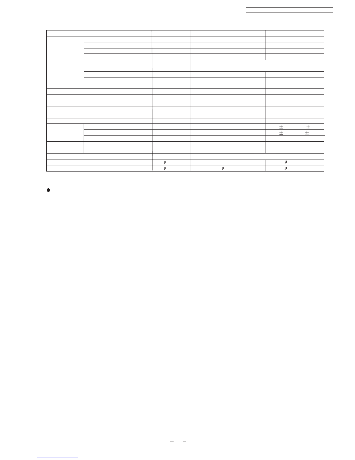
Heat
Exchanger
Description
Tube Material
Fin Type
FPI
Refrigerant Control Device
Refrigeration Oil
Refrigerant (R-22)
Thermostat
Protection Device
Capillary
Air Filter
Refrigerant Circulation Control Device
Compressor Capacitor
Fan Motor Capacitor
Unit CS-PC7DKD CU-PC7DKD
Length
Circulation
Inner Diameter
mm
(c.c)
g
mm
L/min
mm
F, V
F, V
Evaporator
copper
slot type
(Plate fin configuration,forced draft)
2x8 1x24
Condenser
copper
Corrugation type
18
610x168x25.4
-
-
-
-
-
-
-
Electronic Control
P.P Honeycomb
17
575.8x504x12.7
Capillary Tube
SUNISO 4GDID or
ATMOS M60(M56)
450(*)
O.L.P.(25A/230V)
-
Capillary
-
F,20 400V
F,2.0 400VF,1.5 400V
Dimensions
Rows/Stage
810 10
7.0 0.2
1.3
Specifications are subject to change without notice for further improvement.
* 60g for air purging is not included.
CS-PA7DKD / CU-PA7DKD / CS-PC7DKD / CU-PC7DKD
11

14
0.5
1.3
Cooling Capacity
Moisture Removal
Power Source
Airflow Method
Air Circulation
Indoor Air (low)
Indoor Air (medium)
Indoor Air (high)
Outdoor Air
Noise Level
Electrical
Data
Piping Connection Port(Flare piping)
Piping Size(Flare piping)
Drain Hose
Power Supply Cord Length
(Number of core-wire)
Dimensions
Net Weight
Compressor
Air Circulation
Unit
kW
L/h
Phase
V
Cycle
OUTLET
INTAKE
m /min
3
m /min
3
m /min
3
m /min
3
dB(A)
W
A
W/W
A
Input
Running Current
EER
Starting Current
Inner Diameter
Length
Height
Width
Depth
Type
Motor Type
Rated Output
Type
Motor Type
Fan
Speed
Low
Med
High
Rated Output
Input
Inch
inch
Inch
inch
mm
m
mm
mm
mm
kg
W
W
W
rpm
CS-PC9DKD CU-PC9DKD
2.50
1.40
Single
220 / 230
50
SIDE VIEW
TOP VIEW
6.5
7.4
8.5
-
-
-
-
High48
High30,Low28
860
4.00
2.91
20.0
G:half union3/8"
L:half union1/4"
G:gas side3/8"
L:liquid side1/4"
G:3-way valve3/8"
L:2-way valve1/4"
G:gas side3/8"
L:liquid side1/4"
-
-
-
-
-
-
-
m
3 core-wire/1.0mm
2
-
-
-
Cross-flow fan
Induction(4 pole)
-
13
870 60
980 60
1130 60
Rotary(1 cylinder)
Rolling piston type
Induction(2 pole)
750
Propeller fan
Induction(6pole)
-
28
-
-
800 60
-
rpm
rpm
250
770
205
7.5
530
650
230
23
CS-PA7DKD / CU-PA7DKD / CS-PC7DKD / CU-PC7DKD
12
Heat
Exchanger
Description
Tube Material
Fin Type
FPI
Refrigerant Control Device
Refrigeration Oil
Refrigerant (R-22)
Thermostat
Protection Device
Capillary
Air Filter
Refrigerant Circulation Control Device
Compressor Capacitor
Fan Motor Capacitor
Unit CS-PC9DKD CU-PC9DKD
Length
Circulation
Inner Diameter
mm
(c.c)
g
mm
L/min
mm
Evaporator
copper
slot type
(Plate fin configuration,forced draft)
2x12
1x24
Condenser
copper
Corrugation type
18
610x252x25.4
-
-
-
-
-
-
-
Electronic Control
P.P Honeycomb
17
575.8x504x12.7
Capillary Tube
SUNISO 4GDID or
ATMOS M60(M56)
430(*)
O.L.P.(30A/230V)
-
Capillary
Dimensions
Rows/Stage
590 20
10.1 0.2
1.4
Specifications are subject to change without notice for further improvement.
* 60g for air purging is not included.
F, V
F, V
-
F,25 370V
F,2.0 400VF,1.5 400V
CS-PA7DKD / CU-PA7DKD / CS-PC7DKD / CU-PC7DKD
13

4 Dimensions
Indoor Unit
61
165
49
(410)
(43)
Front View
<Back View>
Installation Plate Hook
Gas Side
Liquid
Side
Relative position between the unit and the installation plate (Front View)
Drain Port
770
Air intake
250
49
61
5
Side view
205
Air outlet
Left Piping
Hole
Right Piping
Hole
(79)
OFF
MODE
TEMP
OFF/ON
ON
CANCEL
SET
STD
TIMER
FANSPEED
AIRSWING
125
16.5
56
B
D
D
229
118.8
6
15.5
20
26.5
(382)
(452)
109.2
144.2
(680)
6
15.5
20
26.5
Unit : mm
E
B
C
B
CS-PA7DKD / CU-PA7DKD / CS-PC7DKD / CU-PC7DKD
14
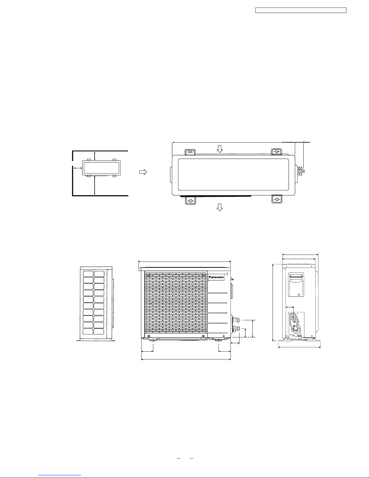
Outdoor Unit
CU-PA7DKD
650
61.6
10cm
100cm
Required space for installation
<Front View>
<Side View>
<Top View>
Unit : mm
123.8
62.2
61.6
88 88
650
668
250
230
530
55.8
293
Air intake
Air outlet
CU-PA9DKD
CU-PC7DKD
CU-PC9DKD
CS-PA7DKD / CU-PA7DKD / CS-PC7DKD / CU-PC7DKD
10cm
15
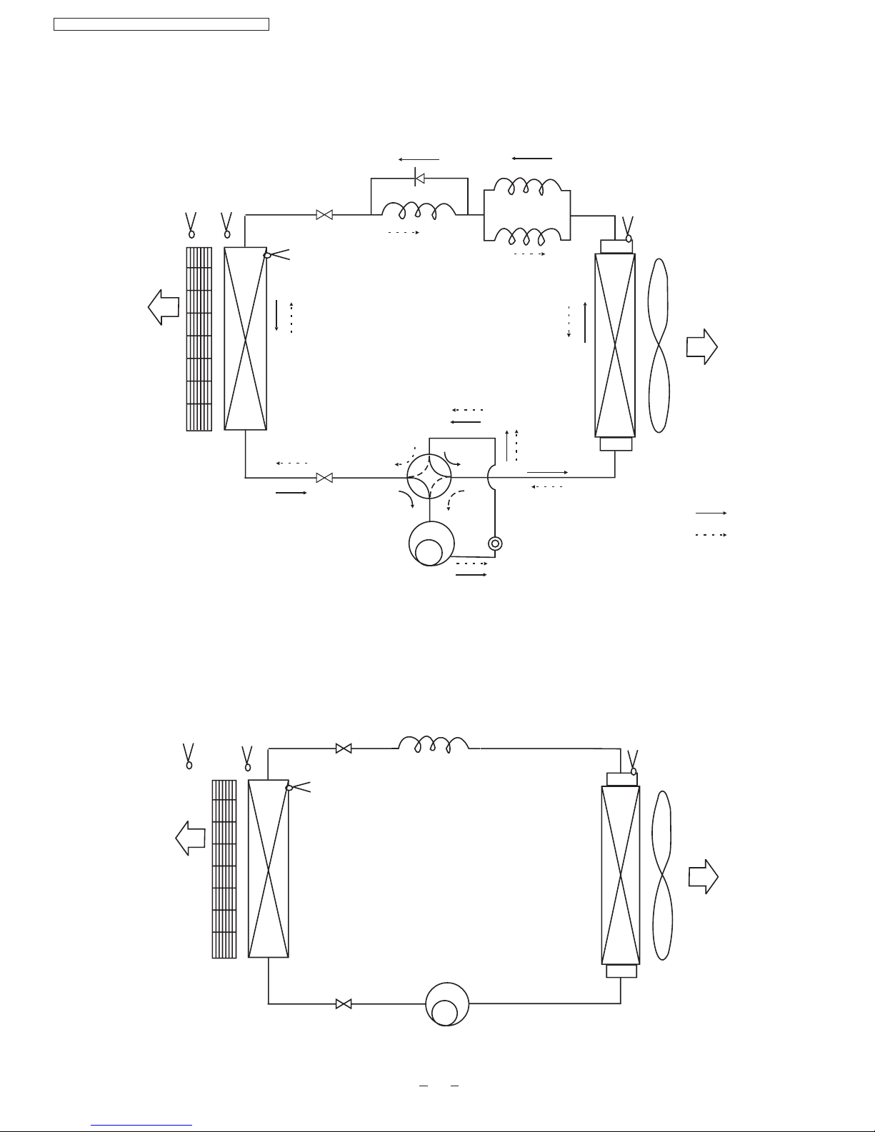
CS/CU-PA7DKD
CS/CU-PA9DKD
5 Refrigeration Cycle Diagram
INTAKEAIR
SENSOR
PIPING
SENSOR
4-way valve
PIPING
SENSOR
INTAKEAIR
SENSOR
INTAKEAIR
SENSOR
PIPING
SENSOR
PIPING
SENSOR
PIPING
SENSOR
PIPING
SENSOR
CS/CU-PC7DKD
CS/CU-PC9DKD
AIR QUALITY
SENSOR
Cooling
Heating
AIR QUALITY
SENSOR
CS-PA7DKD / CU-PA7DKD / CS-PC7DKD / CU-PC7DKD
16
CS-PA7DKD/CU-PA7DKD
6 Block Diagram
FM
FM
2
CR201
3
4
1
RY-HOT
SSR202
SSR201
FUSE
RY-PWR
OUTDOOR UNIT
Receiver
Remote
Control
FM
4-Valve
Compressor
Sensor
Indicator
Piping Sensor
O.L.P.
INDOOR UNIT
CS-PA9DKD/CU-PA9DKD
CS-PA7DKD / CU-PA7DKD / CS-PC7DKD / CU-PC7DKD
17
For PA7DKD, the power source is 220V.
For PA9DKD, the power source is 220V-230V.
POWER SUPPLY
AC220V-230V 50Hz
FM
SSR201
SC
FUSE
RY-PWR
FM
Compressor
CS-PC7DKD/CU-PC7DKD
CS-PC9DKD/CU-PC9DKD
Receiver
Remote
Control
Sensor
Indicator
CS-PA7DKD / CU-PA7DKD / CS-PC7DKD / CU-PC7DKD
18
POWER SUPPLY
AC220V-230V 50Hz
For PC7DKD, the power source is 220V.
For PC9DKD, the power source is 220V-230V .
C-R
C-S
INDOOR FAN MOTOR RESISTANCE( )
CONNECTING
Y-B M
Y-R A
CS-PA7DKD CS-PA9DKD
CWA921308 CWA921329
395
325
275
260
Y-B
Y-R
CWA951419 CWA951419
COMPRESSOR TERMINAL
Signal Receiver
Remote Control
CN-RCV
BR
BL
W
R
B
B
Y/G
INDOOR UNIT
TERMINAL BOARD
FUSE
102 250V3A
YW
B
B
B
Y
Y
R
Y/G
CAPACITOR
CAPACITOR
R
COMPRESSOR
FAN MOTOR
SENSOR(PIPING TEMP.)
Y/G
FUSE
ELECTRONIC CONTROLLER
1
3
5
B
R
Y
FAN MOTOR
W
BR
BL
SENSOR(PIPING TEMP.)
SENSOR(INTAKETEMP.)
INDOOR UNIT
POWER SUPPLY
CORD
POWER SUPPLY
CORD
AC 220V-230 50Hz( )
AC 220V-230 50Hz( )
STEPPING
MOTOR
OUTDOOR UNIT
TERMINAL BOARD
1(L) 2(N) 3 4
1(L) 2(N) 3 4
OUTDOOR UNIT
OUTDOOR FAN MOTOR RESISTANCE( )
CONNECTING
COMPRESSOR RESISTANCE( )
CONNECTING
CU-PA7DKD CU-PA9DKD
CWB092128
3.678
7.240
CU-PA7DKD CU-PA9DKD
CS-PA7DKD/CU-PA7DKD
CS-PA9DKD/CU-PA9DKD
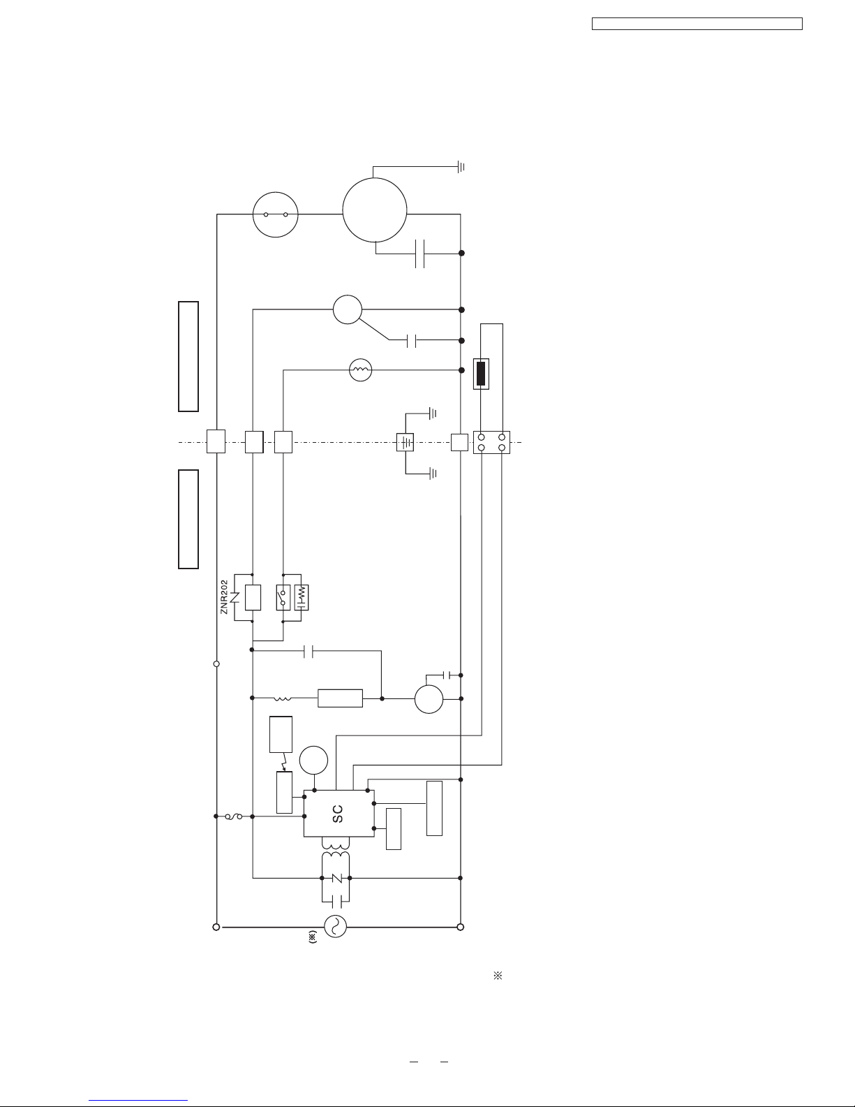
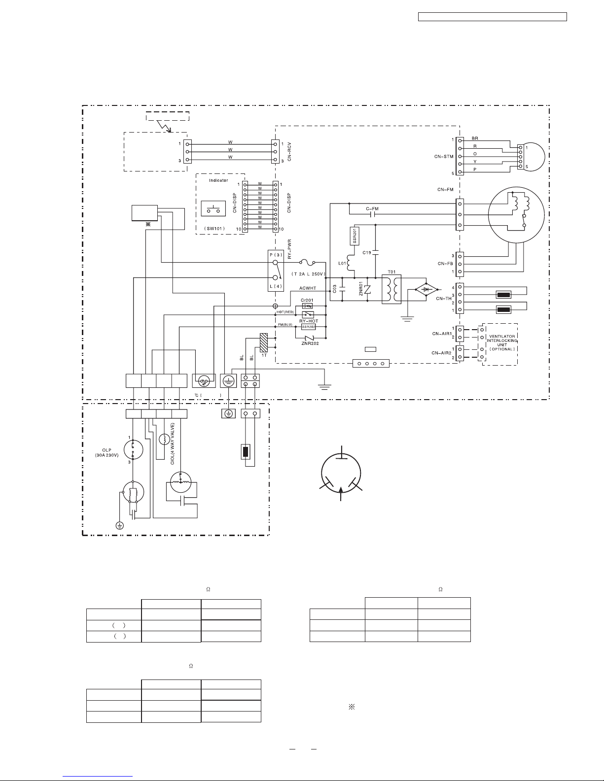
7 Wiring Diagram
R : RED
BL : BLACK
B : BLUE
BR : BROWN
O : ORANGE
GRY : GREY
G : GREEN
Y : YELLOW
W : WHITE
Y/G : YELLOW/GREEN
P : PINK
CWB092312
YELLOW
RED
S
BLUE
R
C
TRADE MARK
AUTO SWITCH
390
390
3.466
3.843
275
260
CS-PA7DKD / CU-PA7DKD / CS-PC7DKD / CU-PC7DKD
19
1234
HA
For PA7DKD, the power source is 220V.
For PA9DKD, the power source is 220V-230V.

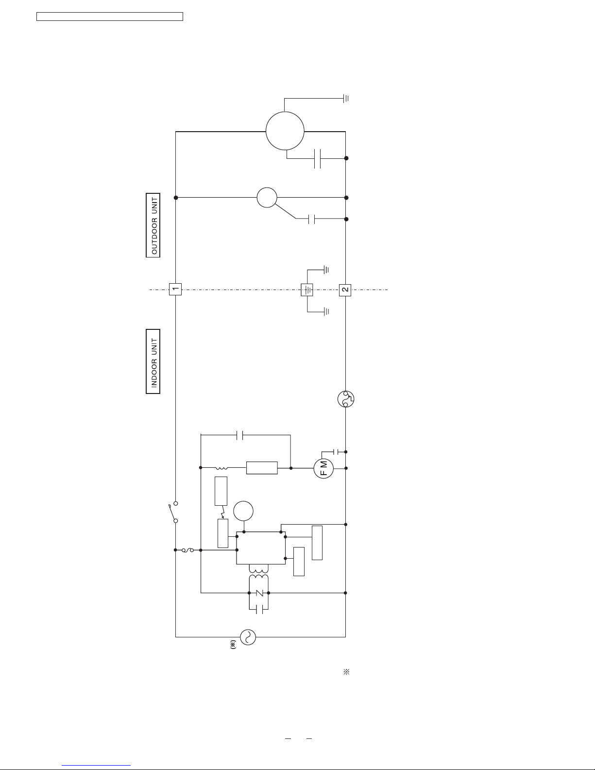
CS-PC7DKD/CU-PC7DKD
CS-PC9DKD/CU-PC9DKD
INDICATOR
AUTO SWITCH
(SW 01)
SIGNALRECEIVER
FUSE
RY-PWR
CN-DISP
CN-DISP
1
10
1
3
CN-RCV
P(3)
L(4)
BR
BL
Y/G
W
C03
ZNR01
L01
C19
T01
SSR01
C-FM
B
FUSE
102 250V 3A)
Y/G
CN-AIR2
CN-AIR1 CN-TH
CN-FB
3
1
3
1
2
4
1
2
1
2
SENSOR(INTAKETEMP.)
SENSOR(PIPING TEMP.)
W
BR
BL
B
R
Y
3
5
1
CN-STM
CN-FM
BR
R
O
Y
P
FANMOTOR
STEPPING
MOTOR
O.L.P
FAN MOTOR
3
1
B
Capacitor
COMPRESSOR
Y/G
Y
B
R
CAPACITOR
B
Y
B
R
Y
OUTDOOR UNIT
REMOTE CONTROL
ELECTRONIC CONTROLLER
POWER SUPPLY
CORD
POWER SUPPLY
CORD
INDOOR UNIT
TERMINAL BOARD
OUTDOOR UNIT
TERMINAL BOARD
INDOOR UNIT
COMPRESSOR TERMINAL
YELLOW
RED
S
BLUE
R
C
TRADE MARK
R : RED
BL : BLACK
B : BLUE
BR : BROWN
O : ORANGE
GRY : GREY
G : GREEN
Y : YELLOW
W : WHITE
Y/G : YELLOW/GREEN
P : PINK
C-R
C-S
INDOOR FAN MOTOR RESISTANCE( )
CONNECTING
Y-B M
Y-R A
CS-PC7DKD CS-PC9DKD
CWA921308
395
325
CWA951427
Y-B
Y-R
CWA951427
OUTDOOR FAN MOTOR RESISTANCE( )
CONNECTING
COMPRESSOR RESISTANCE( )
CONNECTING
CU-PC7DKD CU-PC9DKD
CWB092129
CU-PC7DKD CU-PC9DKD
CWA921329
CWB092279
4.307
7.668
OUTDOOR UNIT
390
390
275
260
275
260
3.072
5.216
CS-PA7DKD / CU-PA7DKD / CS-PC7DKD / CU-PC7DKD
20
1234
HA
For PC7DKD, the power source is 220V.
For PC9DKD, the power source is 220V-230V .
AC 220V-230 50Hz( )
AC 220V-230 50Hz( )
21
8 Operation Details
CS-PA7DKD / CU-PA7DKD / CS-PC7DKD / CU-PC7DKD
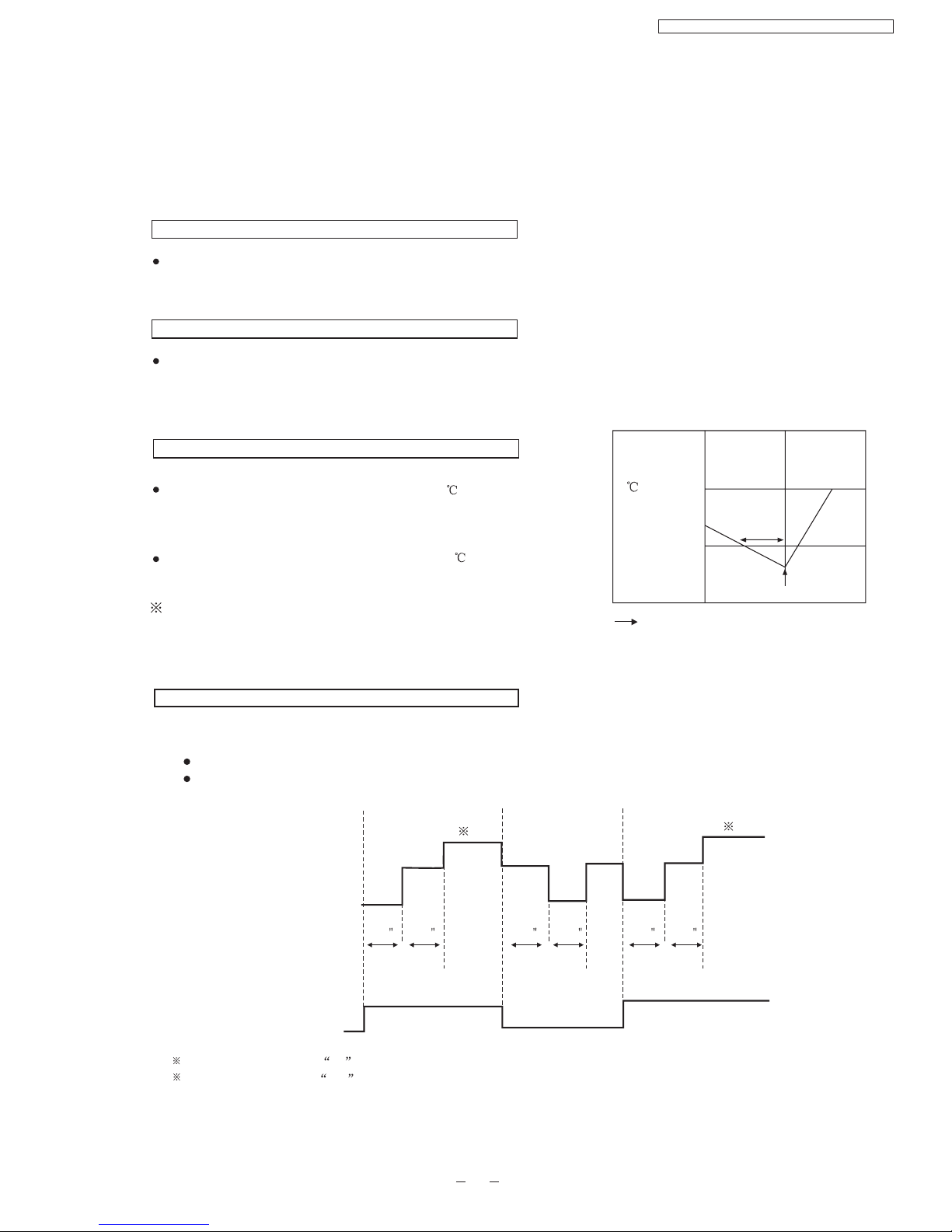
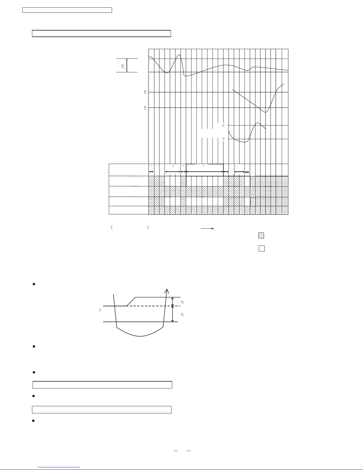
8.1 .Cooling Mode Operation
When selecting the Cooling Mode Operation, the unit will operate according to the setting by the Remote Controller or
the control panel on the indoor unit and the operation is as the following.
Time Delay Safety Control
3 min.----If the compressor stops, it will not restart within 3 minutes.(Protection of compressor).
7 Minutes Time Save Control
7 min.----The unit will automatically operate in 7 minutes even if the room temperature is not reached.
(Prevention of raising the humidity)
Evaporator
Temperature
()
10
2
Restart
4 minutes
Compressor ceases
Time
Anti-Freezing Control
If temperature of evaporator is lower than 2 continuously
for 4 minutes, the compressor will cease to prevent the
evaporator from freezing. Fan speed setting will not be
changed.
When temperature of evaporator reaches 10 ,compressor
will restart.
During Cooling Mode Operation, the Time Delay Safety
Control is available.
Indoor Fan
STOP
Slow
Slow
STOP STOP
Slow Slow
STOP
ON
Compressor
ON
1 Fan speed will be at Hi till the compressor ceases (set temperature reached).
2 Fan speed will be at Me when the compressor restarts.
40 30 40 3020 160
1
2
Automatic Fan Speed Mode
During Cooling Mode Operation, use remote controller to select Automatic Fan Speed.
Deodorization control.
Fan speed will be at the point between "High speed" and "Medium speed".
22
Intake air temperature
Evaporater
temperature
10
2
Start
Stop
1.5
Basic Time
Comp.
Indoor Fan
Outdoor Fan
Operation Indicator
1 1
3
7
Operation status
Time delay safety control
Compressor Test control
Auto restart control
Anti-freezing Control
Time
d-g
g-h
h-o
q-t
:
:
:
:
Operate
Stop
abcdefghi j klmnopqrstuvwxyz
3
4’
1’
Time Graph for Cooling Operation
Set temperature
31
29
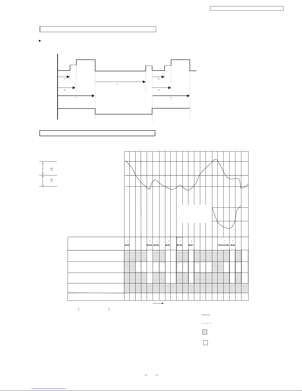
8.2. Soft Dry Mode Operation
When selecting Soft Dry mode operation, the operation will be cooling until the room temperature reaches the set temp on
remote control, and then Soft Dry will be activated. (During Soft Dry Mode the fan of indoor unit will operate at super low
speed. The soft dry mode will run for less than 10 minutes.)
Once Soft Dry mode operation is turned off, indoor fan, compressor and outdoor fan will stop for 6 minutes.
COOLING(OFF)
DRY(ON
DRY(OFF)
DRY
COOLING
COOLING(ON)
DRY(ON)
1.5
1.0
DRY(OFF)
Operation area
Time Delay Safety Protection
During cooling mode operation, if the compressor ceased, it will not restart within 3 minutes.
Anti Freezing Control
Same as the denotation in Cooling Operation.( )
(During Soft Dry Mode Operation, compressor will stop for at least 6 min.)
P21
CS-PA7DKD / CU-PA7DKD / CS-PC7DKD / CU-PC7DKD
23
Automatic Fan Speed
During Soft Dry Operation, use remote controller to select Auto Fan Speed mode.
Indoor Fan Speed is at “Lo-”
70
T2
40
T1
Slo
Lo-
OFF
ON
OFF
10
6
70
T2
40
T1
10
Slo Slo
Lo-
ON
OFF OFF OFF
Indoor
fan
Compressor
Time Graph for soft dry operation
abcdef g hi jklmnopq rst u
Evaporator
temperature
10 C
o
2C
o
Basic Time
Comp.
Indoor Fan
Outdoor Fan
Operation Indicator
666
1
61 1 4
Operation status
Time
Operate
Stop
Cooling mode operation
Soft Dry Mode operation
Super
Low
Super
Low
Super
Low
Super
Low
Low
1.5
Cooling mode operation activated
Intake Air temp
1.0
Cooling mode operation stopped
Soft mode operation activated
Soft dry mode operation stop
Cooling Mode Operation
Soft Dry Mode Operation
Soft Dry Mode Operation Stopped
Compressor Test Operation Control
Anti Freezing Control
a-c,p-r
c-p,r-u
e-f
j-l
q-t
:
:
:
:
:
Slo Slo Slo Slo
Slo Slo
Slo Slo Slo
Slo
Slo
4-way Valve
CS-PA7DKD/CU-PC7DKD / CS-PC7DKD/CU-PC7DKD
 Loading...