

Panasonic CT-L1400 Schematic

CT-L1400
LH13 Chassis
ORDER NO. ITD0306006C1
D10
LCD TV
Specifications
Power Source AC 120V, 60Hz
Power Consumption Average use: 48W
Stand-by condition: 0.6 W
TVsetDC15V,2.8Amax.
LCD 14-inch (356 mm),
4 : 3 aspect ratio LCD panel
Screen Size 11.23" (285.1 mm) (W) × 8.42" (213.8 mm) (H)
Channel Capability VHF-12: UHF-56: Cable-125
Sound
Speaker 4 cm, 2pcs, 16 9
Headphones M3 (3.5 mm) Jack × 1
FEATURES CLOSED CAPTION V-Chip
Operating Conditions Temperature: 41 °F - 95 °F(5 °C - 35 °C)
Humidity: 5% - 90% RH (non-condensing)
Connection Terminals
INPUT VIDEO (RCA PIN Type × 1) × 2 1.0 Vp-p (75 9)
S-VIDEO (MINI DIN 4 pin × 1) × 2 Y: 1 Vp-p (75 9), C: 0.286 Vp-p (75 9)
AUDIO L-R (RCA PIN Type × 2) × 2 0.5 Vrms
COMPONENT VIDEO INPUT Y 1.0 Vp-p (including synchronization)
PB/P
R
AUDIO L-R (RCA PIN Type × 2) 0.5Vrms
Dimensions (W x H x D)
Including TV Stand 14.37" (365 mm) × 14.34" (364.2 mm) × 8.46" (215
mm)
TV Set Only 14.37" (365 mm) × 13.01" (330.5 mm) × 2.51" (63.7
mm)
±0.35Vp-p
© 2003 Matsushita Electric Industrial Co., Ltd. All
rights reserved. Unauthorized copying and
distribution is a violation of law.
CT-L1400
Mass (Weight) 9.701 lb. (4.4 kg) Net
Note:
Design and Specifications are subject to change without notice. Weight and Dimensions shown are approximate.
CONTENTS
Page Page
1 Safety Precautions 3
1.1. General Guidelines
2 Prevention of Electro Static Discharge (ESD) to
Electrostatically Sensitive (ES) Devices
3 About lead free solder (PbF)
4 Self-check function
4.1. How to access
4.2. Screen display
4.3. Display phenomenon and treatment method
5 Chassis Board Layout
6 Before servicing
6.1. Kind and location of the flexible cable
6.2. How to remove the connector
7 Disassembly for Service
7.1. Rear cover
7.2. AP-BOARD
7.3. DG-Board
7.4. V-Board
7.5. Speaker (L, R)
7.6. B-Board
7.7. K-Board
7.8. LCD panel
8 Adjustment method
8.1. How to enter into adjustment mode
8.2. Cancellation
8.3. Contents of adjustment mode
10
11
11
11
12
12
13
15
15
15
15
3
3
4
5
5
5
5
6
7
7
8
9
9
8.4. Video level adjustment
8.5. Flicker Adjustment
8.6. MTS Adjustment
9 Hotel Mode
10 Conductor Views
10.1. AP-Board
10.2. DG-Board
10.3. B, K and V-Board
11 Block and Schematic Diagr am
11.1. Schematic Diagram Notes
11.2. Power Block Diagram
11.3. Signal Block Diagram
11.4. AP-Board (1 of 2) Schematic Diagram
11.5. AP-Board (2 of 2) Schematic Diagram
11.6. DG-Board (1 of 3) Schematic Diagram
11.7. DG-Board (2 of 3) Schematic Diagram
11.8. DG-Board (3 of 3) Schematic Diagram
11.9. B, K, and V-Board Schematic Diagram
12 Parts Location & Mechanical Replacement Parts List
12.1. Parts Location
12.2. Packing Exploded View
12.3. Mechanical Replacement Parts List
13 Replacement Parts List
13.1. Replacement Parts List Notes
13.2. Electrical Replacement Parts List
16
19
20
21
29
29
31
32
33
33
34
36
38
39
40
41
42
43
45
45
46
47
48
48
49
2
1 Safety Precautions
1.1. General Guidelines
1.When servicing, observe the original lead dress. If a short circuit is found, replace all parts which have been overheated or
damaged by the short circuit.
2.After servicing, see to it that all the protective devices such as insulation barriers, insulation papers shields are properly
installed.
3.After servicing, make the following leakage current checks to prevent the customer from being exposed to shock hazards.
CT-L1400
1.1.1. Leakage Current Cold Check
1.Unplug the AC cord and connect a jumper between the two
prongs on the plug.
2.Measure the resistance value, with an ohmmeter, between
the jumpered AC plug and each exposed metallic cabinet
part on the equipment such as screwheads, connectors,
control shafts, etc. When the exposed metallic part has a
return path to the chassis, the reading should be between
1M9 and 5.2M9.
When the exposed metal does not have a return path to the
chassis, the reading must be
Figure 1
.
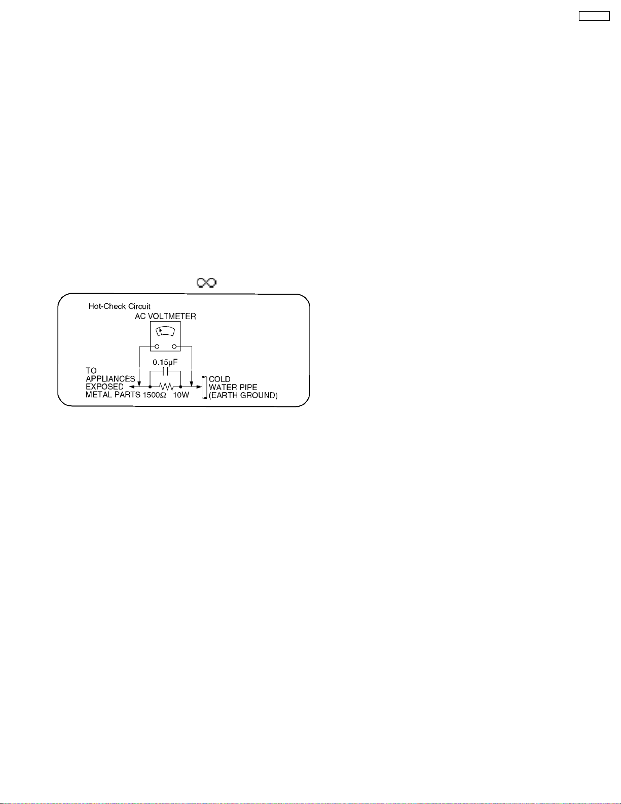
1.1.2. Leakage Current Hot Check (See
Figure 1.)
1.Plug the AC cord directly into the AC outlet. Do not use an
isolation transformer for this check.
2.Connect a 1.5k9, 10 watts resistor, in parallel with a 0.15µF
capacitors, between each exposed metallic part on the set
and a good earth ground such as a water pipe, as shown in
Figure 1.
3.Use an AC voltmeter, with 1000 ohms/volt or more
sensitivity, to measure the potential across the resistor.
4.Check each exposed metallic part, and measure the
voltage at each point.
5.Reverse the AC plug in the AC outlet and repeat each of the
above measurements.
6.The potential at any point should not exceed 0.75 volts
RMS. A leakage current tester (Simpson Model 229 or
equivalent) may be used to make the hot checks, leakage
current must not exceed 1/2 milliamp. In case a
measurement is outside of the limits specified, there is a
possibility of a shock hazard, and the equipment should be
repaired and rechecked before it is returned to the
customer.
2 Prevention of Electro Static Discharge (ESD) to
Electrostatically Sensitive (ES) Devices
Some semiconductor (solid state) devices can be damaged easily by static electricity. Such components commonly are called
Electrostatically Sensitive (ES) Devices. Examples of typical ES devices are integrated circuits and some field-effect transistors and
semiconductor "chip" components. The following techniques should be used to help reduce the incidence of component damage
caused by electro static discharge (ESD).
1.Immediately before handling any semiconductor component or semiconductor-equipped assembly, drain off any ESD on your
body by touching a known earth ground. Alternatively, obtain and wear a commercially available discharging ESD wrist strap,
which should be removed for potential shock reasons prior to applying power to the unit under test.
2.After removing an electrical assembly equipped with ES devices, place the assembly on a conductive surface such as alminum
foil, to prevent electrostatic charge buildup or exposure of the assembly.
3.Use only a grounded-tip soldering iron to solder or unsolder ES devices.
4.Use only an anti-static solder removal device. Some solder removal devices not classified as "anti-static (ESD protected)" can
generate electrical charge sufficient to damage ES devices.
5.Do not use freon-propelled chemicals. These can generate electrical charges sufficient to damage ES devices.
6.Do not remove a replacement ES device from its protective package until immediately before you are ready to install it. (Most
replacement ES devices are packaged with leads electrically shorted together by conductive foam, alminum foil or comparable
conductive material).
7.Immediately before removing the protective material from the leads of a replacement ES device, touch the protective material
to the chassis or circuit assembly into which the device will be installed.
3
CT-L1400
Caution
Be sure no power is applied to the chassis or circuit, and observe all other safety precautions.
8.Minimize bodily motions when handling unpackaged replacement ES devices. (Otherwise hamless motion such as the brushing
together of your clothes fabric or the lifting of your foot from a carpeted floor can generate static electricity (ESD) sufficient to
damage an ES device).
3 About lead free solder (PbF)
Note: Lead is listed as (Pb) in the periodic table of elements.
In the information below, Pb will refer to Lead solder, and PbF will refer to Lead Free Solder.
The Lead Free Solder used in our manufacturing process and discussed below is (Sn+Ag+Cu).
That is Tin (Sn), Silver (Ag) and Copper (Cu) although other types are available.
This model uses Pb Free solder in it’s manufacture due to environmental conservation issues. For service and repair work, we’d
suggest the use of Pb free solder as well, although Pb solder may be used.
PCBs manufactured using lead free solder will have the PbF within a leaf Symbol
Caution
·
· Pb free solder has a higher melting point than standard solder. Typically the melting point is 50 ~ 70 °F (30~40°C) higher.
· ·
Please use a high temperature soldering iron and set it to 700 ± 20 °F (370 ± 10 °C).
·
· Pb free solder will tend to splash when heated too high (about 1100 °F or 600 °C).
· ·
If you must use Pb solder, please completely remove all of the Pb free solder on the pins or solder area before applying Pb
solder. If this is not practical, be sure to heat the Pb free solder until it melts, before applying Pb solder.
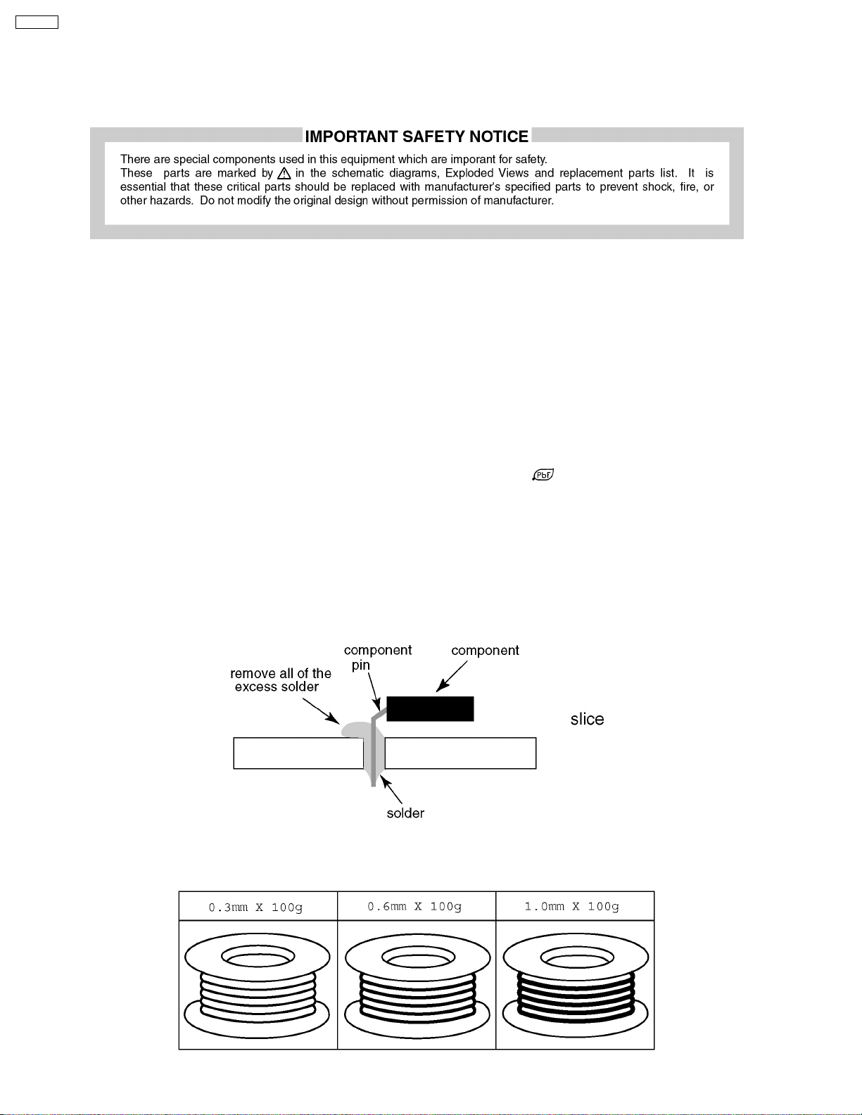
·
· After applying PbF solder to double layered boards, please check the component side for excess solder which may flow onto
· ·
the opposite side. (see figure below)
Suggested Pb free solder
There are several kinds of Pb free solder available for purchase. This product uses Sn+Ag+Cu (tin, silver, copper) solder.
However, Sn+Cu (tin, copper), Sn+Zn+Bi (tin, zinc, bismuth) solder can also be used.
stamped on the back of PCB.
4
4 Self-check function
When phenomena like "the power fails from time to time" or "the video/audio fails from time to time" can not be confirmed at the
time of servicing, the self-check function can be used to confirm the occurrence and to limit the scope for the defective circuits.Also,
when "the power fails from time to time", display on the screen can be used to confirm the occurrence and to limit the scope for
the defective circuits.
Any programmed channels, channels caption data and some other user defined settings will be erased and return to factory setting.
4.1. How to access
4.1.1. Access
Produce TV reception screen and, while pressing [VOLUME-] button on the main unit, press [SLEEP] button on the remote
controller unit simultaneously.
4.1.2. Exit
When one of the buttons for channel selection etc. is pressed, the display returns to the normal screen.
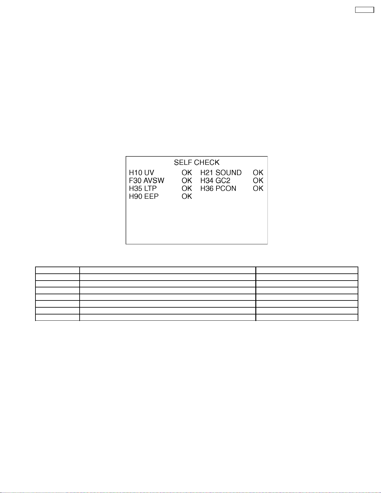
4.2. Screen display
CT-L1400
4.3. Display phenomenon and treatment method
Display symbol Phenomenon/condition Treatment method
H10 No output of video and audio. Replace tuner (TNR001A (B-BOARD)).
H21 No audio output. Surround function not effective. Replace IC2300 (AP-BOARD).
F30 No video and audio output. Input switching disabled. Replace IC3000 (AP-BOARD).
H34 Black and white stripes pattern. Enhanced back light. Replace IC4003 (DG-BOARD).
H35 No video Replace IC6400 (DG-BOARD).
H36 No video Replace IC6300 (DG-BOARD).
H90 Power interrupted with self-check. Replace IC1002 (DG-BOARD).
* Any button operation or switching off the power will reset the self-check data.
5
CT-L1400
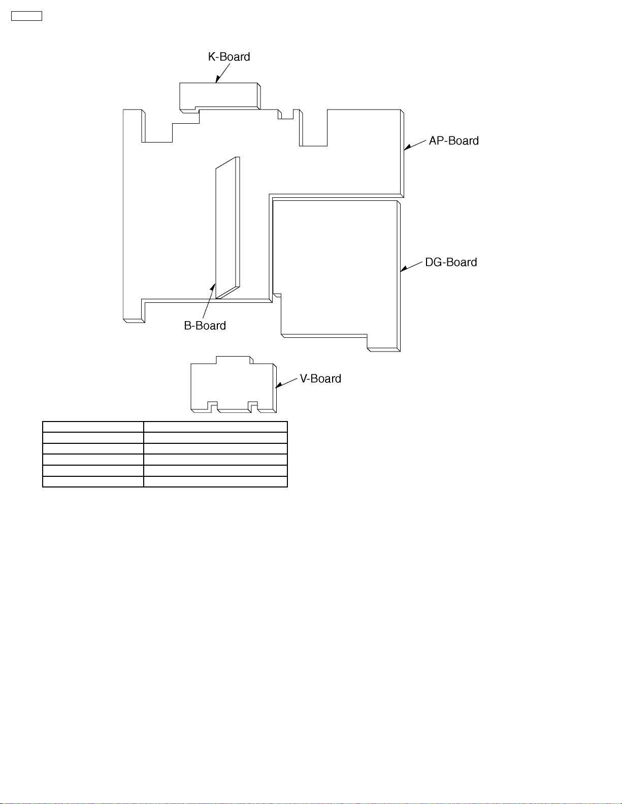
5 Chassis Board Layout
Board Name Function
AP-Board Audio, Power, Inverter, AV SW
B-Board Tuner
DG-Board GC2, PCN, MICOM, EEPROM
K-Board Switch
V-Board Remote sensor, LED
6
6 Before servicing
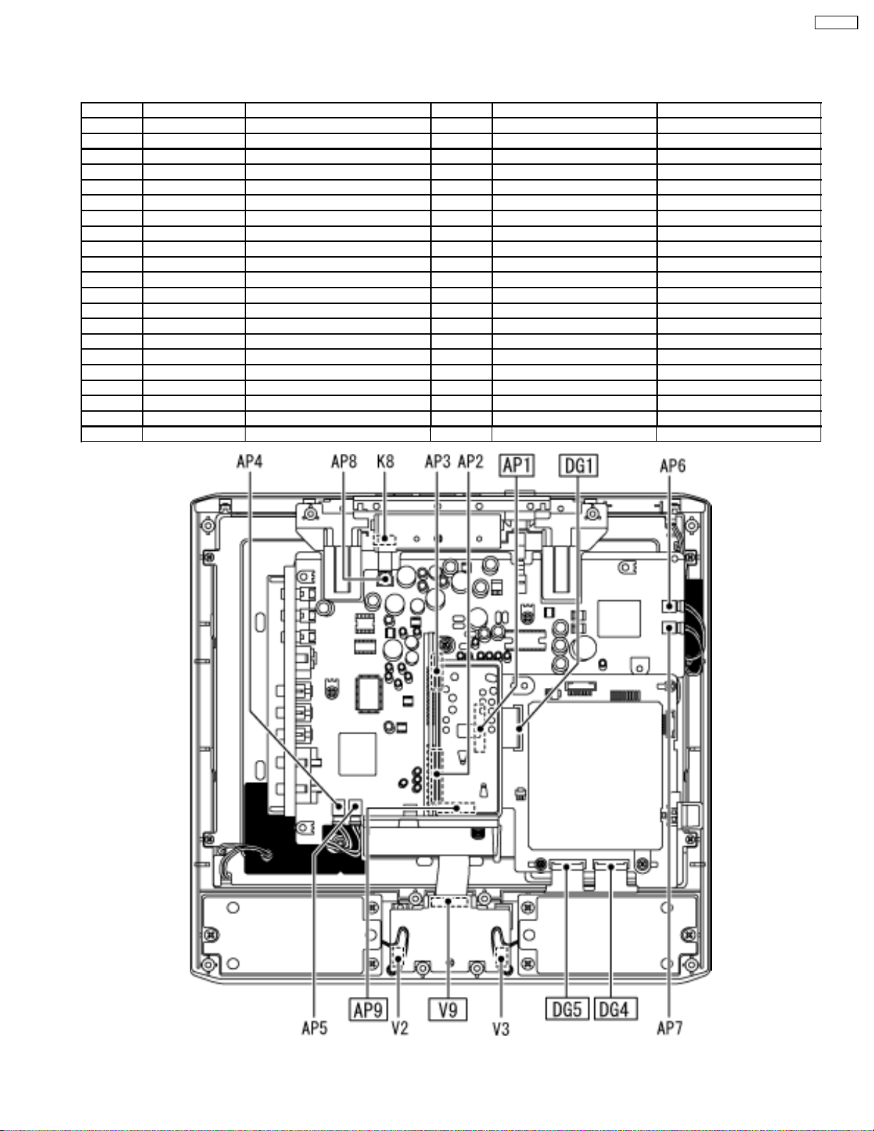
6.1. Kind and location of the flexible cable
Ref No. Flexible cable Connector type Pins Location Opposite Ref No.
AP1 l type1 50 pin AP-BOARD DG1
AP2 - - 15 pin AP-BOARD B2
AP3 - - 9pin AP-BOARD B3
AP4 - - 2pin AP-BOARD Back Light (U)
AP6 - - 2 AP-BOARD Back Light (U)
AP8 - - 4pin AP-BOARD K8
AP9 l type2 12 pin AP-BOARD V9
AP10 - - 11 pin AP-BOARD BL1
B2 - - 15 pin B-BOARD AP2
B3 - - 9pin B-BOARD AP3
BL1 - - 11 pin BL-BOARD AP10
BL4 - - 2pin BL-BOARD Back Light (D)
BL6 - - 2pin BL-BOARD Back Light (D)
DG1 l type3 50 pin DG-BOARD AP10
DG4 l type5 40 pin DG-BOARD LCD Panel
DG5 l type5 40 pin DG-BOARD LCD Panel
K8 - - 4pin K-BOARD AP8
P101 l type5 50 pin LCD Panel DG3
V2 - - 2pin V-BOARD Speaker (R)
V3 - - 2pin V-BOARD Speaker (L)
V9 l type4 12 pin V-BOARD AP9
CT-L1400
7
CT-L1400
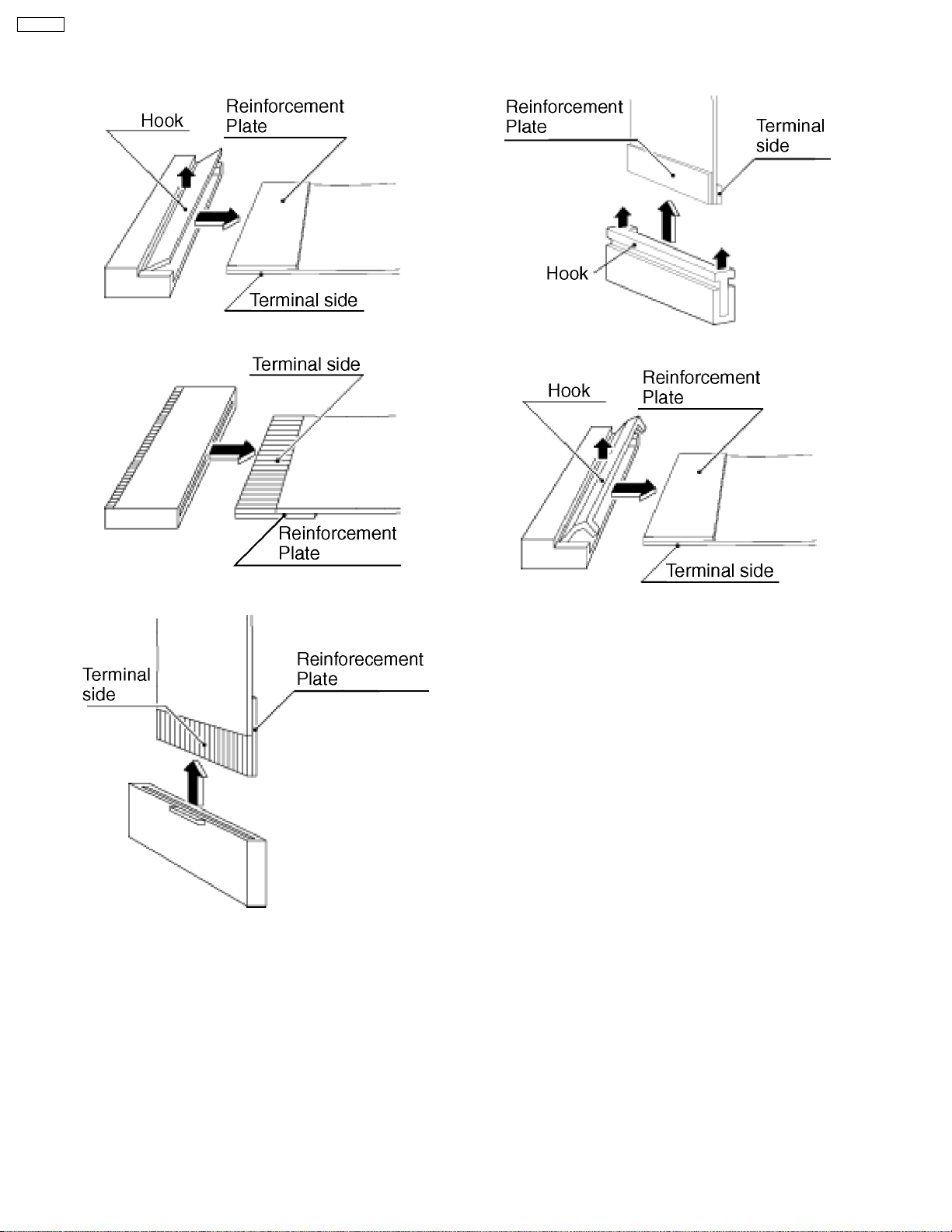
6.2. How to remove the connector
Connector type1
Connector type2
Connector type4
Connector type5
Connector type3
8
7 Disassembly for Service
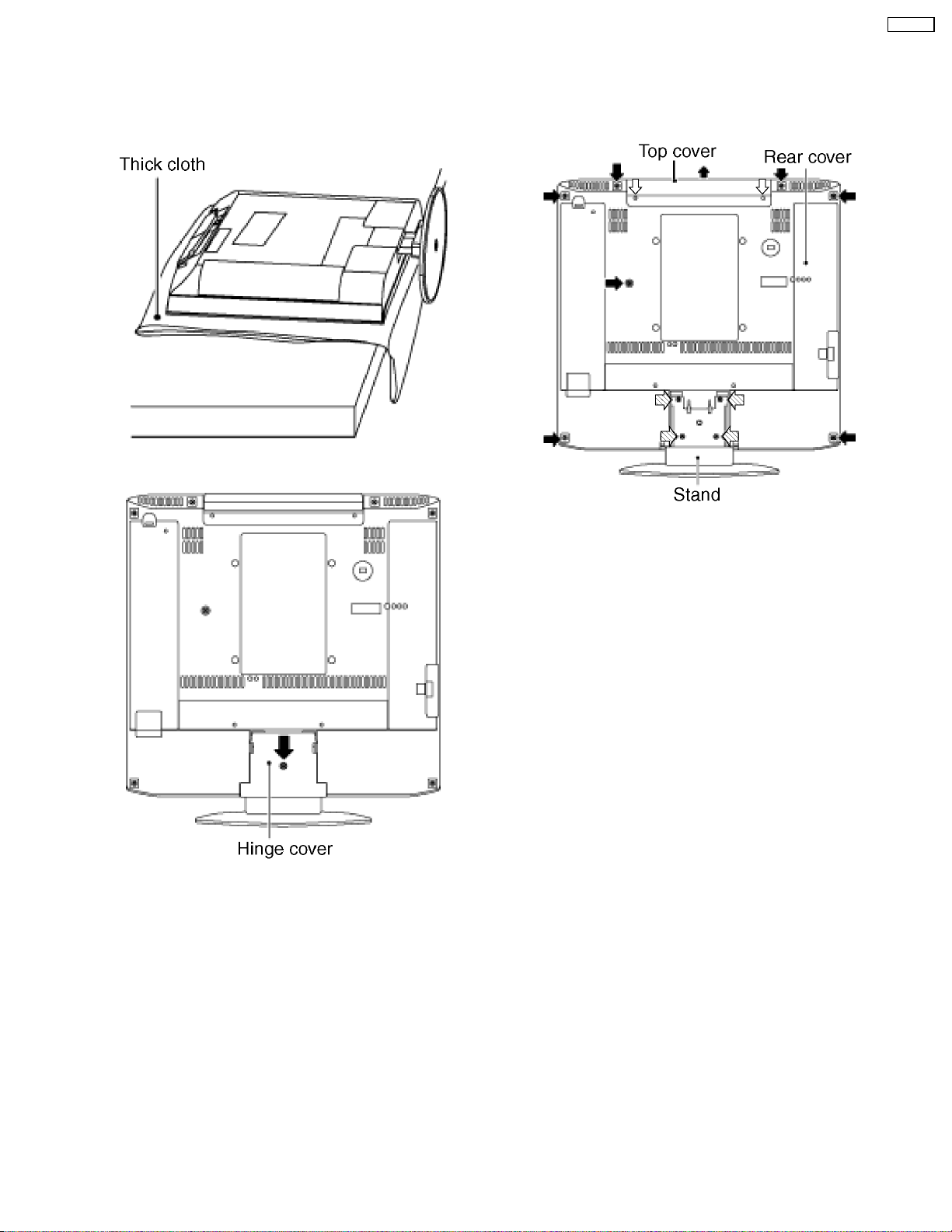
7.1. Rear cover
1.T hick cloth and so on is down not to damage a LCD screen,
and the unit is pushed down.
2.Remove the screw (1 pcs), and detach the hinge cover and
the AV cable cover.
CT-L1400
3.Remove the screws (7 pcs), the screws (2 pcs), and the
screws (4 pcs), and detach the rear cover and top cover.
9
CT-L1400
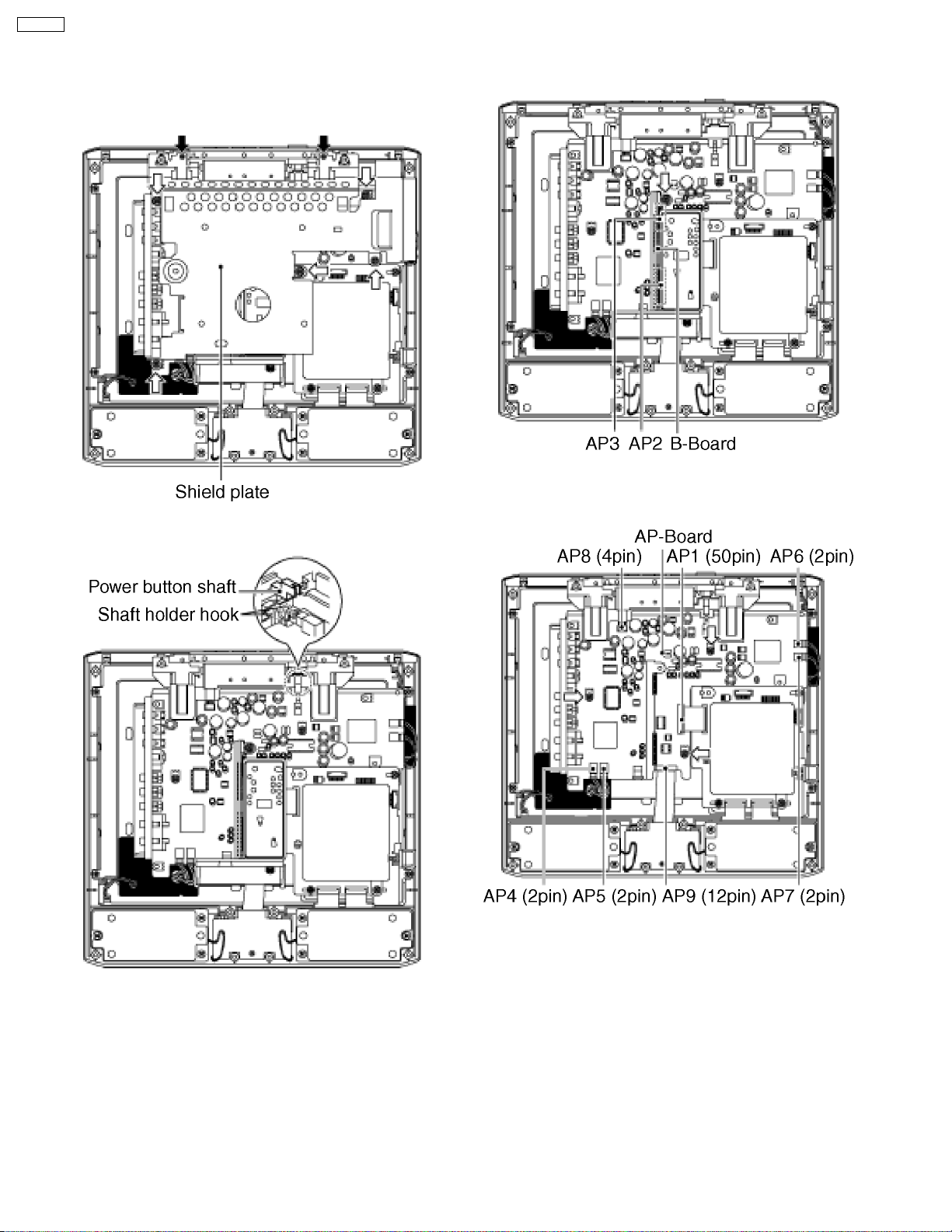
7.2. AP-BOARD
1.Remove the rear cover.
2.Remove the screws (5 pcs) and the screws (2 pcs) and
detach the shield plate.
3.Disengage the shaft holder hook and detach the power
button shaft.
4.Remove the screw (1 pcs) and disconnect the couplers (B2
(AP2) and B3 (AP3)) between B-Board and the AP-Board.
5.Disconnect the couplers (AP4, AP5, AP6, AP7 and AP8)
the flexible cable (AP1 and AP9) and remove the screws (3
pcs) and detach the AP-Board.
Caution:
PCB Fixing screws driving torque: 0.2-0.3 N·m (2-3kg·mm)
Do not tighten screws so hard.
10
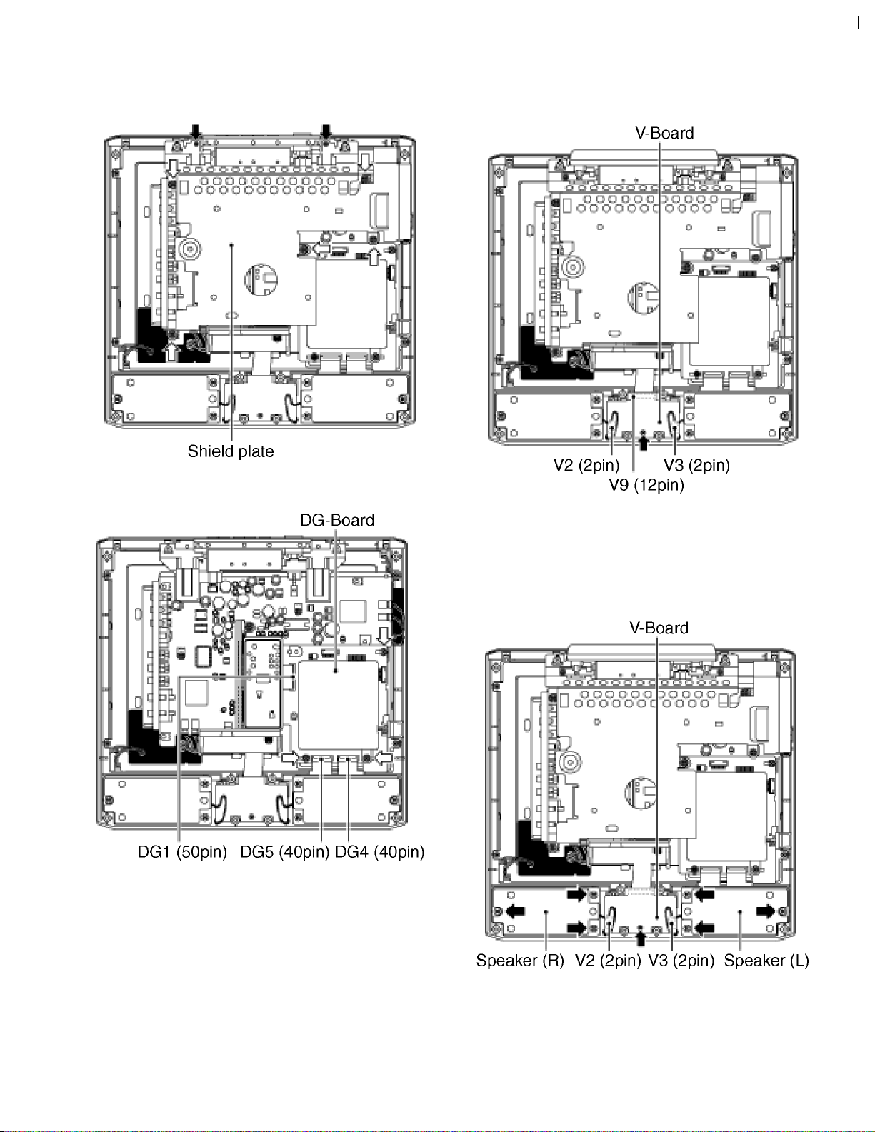
7.3. DG-Board
CT-L1400
7.4. V-Board
1.Remove the rear cover.
2.Remove the screws (5 pcs) and the screws (2 pcs) and
detach the shield plate.
3.Disconnect the flexible cable (DG4 and DG5) and remove
the screws (2 pcs) and detach the DG-Board.
1.Remove the rear cover.
2.Remove the screw (1 pcs) and disconnect the couplers (V2
and V3) and the flexible cable (V9) and detach the V-Board.
Caution:
PCB Fixing screws driving torque: 0.2-0.3 N·m (2-3kg·mm)
Do not tighten screws so hard.
7.5. Speaker (L, R)
1.Remove the rear cover.
2.Remove the screw (1 pcs) and the screws (6 pcs) and
disconnect the couplers (V2 and V3) and the Speakers (L,
R).
11
CT-L1400
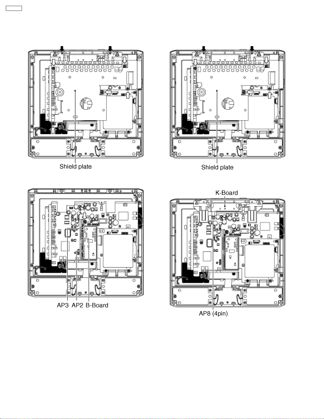
7.6. B-Board
7.7. K-Board
1.Remove the rear cover.
2.Remove the screw (5 pcs) and the screws (2 pcs) and
detach the shield plate.
3.Remove the screw (1 pcs) and disconnect the couplers (B2
(AP2) and B3 (AP3)) between B-Board and the AP-Board.
1.Remove the rear cover.
2.Remove the screws (5 pcs) and the screws (2 pcs) and
detach the shield plate.
3.Disconnect the coupler (AP8) and disengage the hook (2
pcs) and detach the K-Board.
Caution:
PCB Fixing screws driving torque: 0.2-0.3 N·m (2-3kg·mm)
Do not tighten screws so hard.
Caution:
PCB Fixing screws driving torque: 0.2-0.3 N·m (2-3kg·mm)
Do not tighten screws so hard.
12
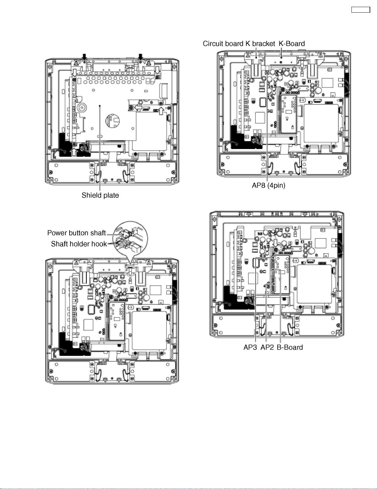
7.8. LCD panel
1.Remove the rear cover.
2.Remove the screws (5 pcs) and the screws (2 pcs) and
detach the shield plate.
CT-L1400
4.Disconnect the coupler (AP8) and detach the circuit board
K bracket with K-Board.
3.Disengage the shaft holder hook and detach the power
button shaft.
5.Remove the screw (1 pcs) and disconnect the couplers (B2
(AP2) and B3 (AP3)) between B-Board and the AP-Board.
13

CT-L1400
6.Disconnect the couplers (AP4, AP6, BL4 and BL6) and the
flexible cable (AP9, DG4 and DG5) and remove the screws
(7 pcs) and detach the AP-Board, DG-Board and BL-Board.
7.Remove the screws (2 pcs), detach the LCD panel.
14
8 Adjustment method
8.1. How to enter into adjustment mode
While pressing [VOLUME-] button of the main unit, press [RECALL] button of the remote control transmitter three times in a row
(within 2 seconds).
8.1.1. Adjustment method.....Use the remote control.
“1” button...Main items Selection in forward direction
“2” button...Main items Selection in reverse direction
“3” button...Sub items Selection in forward direction
“4” button...Sub items Selection in reverse direction
8.2. Cancellation
Switch off the power with the [POWER] button on the main unit or the [POWER] button on the remote control.
8.3. Contents of adjustment mode
·
· Value is shown as a hexadecimal number.
· ·
·
· Preset value differs depending on models.
· ·
·
· After entering the adjustment mode, take note of the value in each item before starting adjustment.
· ·
Main item Sub item Remarks Sample Data
MAIN YGAIN Video level (RF, video, component) 96
B-Y Video level (RF, video, component) 9C
R-Y Video level (RF, video, component) 3D
FLICKR Panel flicker 5A
SUB COLOR Sub color 28
TINT Sub tint 80
BACK-L Sub Back light B0
BRIGHT Sub Bright 800
B-Y-G B-Y Gain 40
R-Y-A R-Y demodulation axis 00
GAMMA R-GAIN Red gain E6
G-GAIN Green gain FF
B-GAIN Blue gain EB
R-CENT Red gain 88
G-CENT Green gain 80
B-CENT Blue gain AC
OPT OPT00 (TV) 00
RM CODE Remote Control Transmitter Code A
MTS MTSIN RF Audio input level 1A
SEPAH Stereo separation Hi 1C
SEPAL Stereo separation Low 06
CT-L1400
Note:
GAMMA adjustment is for factory adjustment only. Do not change the value.
15
CT-L1400
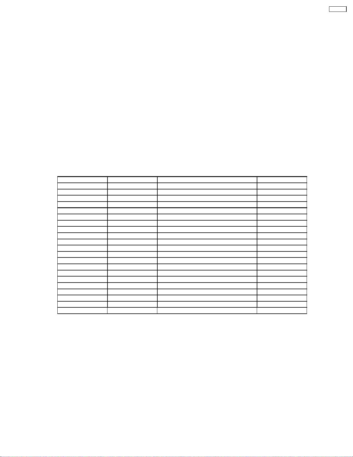
8.4. Video level adjustment
Test Point Location
8.4.1. NTSC picture R F
Measuring instrument Connection Mode
Remote control transmitter
RF signal
Oscilloscope
·
· Receive 75% color bar signal
· ·
·
· Enter the adjustment mode and adjust the amplitude level of each signal in the following steps.
· ·
TP236~TP239 (GND) :R
TP237~TP239 (GND) :G
TP238~TP239 (GND) :B
ASPECT : 4:3
PIC MODE : STANDARD
BACK LIGHT: +30
AI PICTURE : OFF
1.Y signal
With [VOLUME+/-] buttons of the remote control transmitter, adjust the value appearing below YGAIN indication so that the
value below MAX indication becomes B8.
2.B-Y signal (TP238)
With [VOLUME+/-] buttons of the remote control transmitter, adjust the value appearing below B-Y indication so that the
amplitude (white-blue) at TP238 becomes 0±0.03V.
3.R-Y signal (TP236)
With [VOLUME+/-] buttons of the remote control transmitter, adjust the value appearing below R-Y indication so that the
amplitude (white-red) at TP236 becomes 0±0.03V.
16
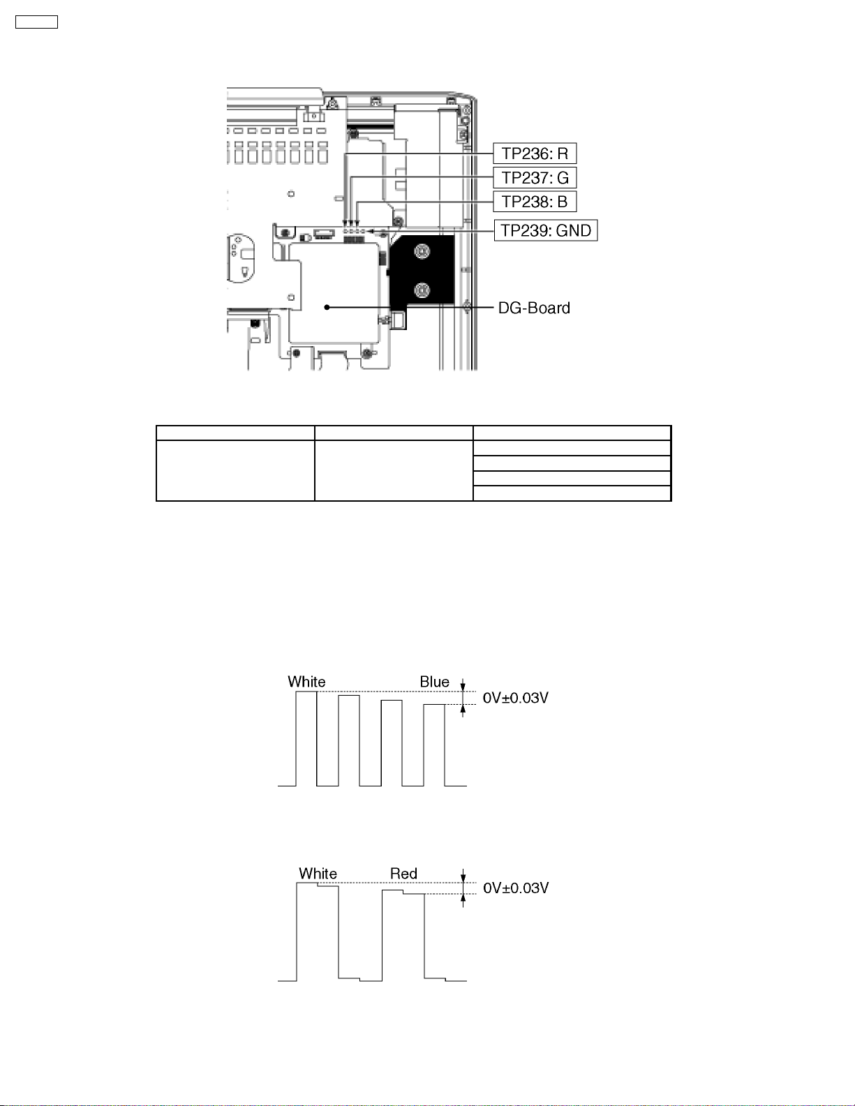
8.4.2. NTSC picture video (VBS)
Measuring instrument Connection Mode
Remote control transmitter
Video signal
Oscilloscope
·
· Receive 100% color bar signal at video input 1.
· ·
·
· Enter the adjustment mode and adjust the amplitude level of each signal in the following steps.
· ·
1.Y signal
With [VOLUME+/-] buttons of the remote control transmitter, adjust the value appearing below YGAIN indication so that the
value below MAX indication becomes B8.
2.B-Y signal (TP238)
With [VOLUME+/-] buttons of the remote control transmitter, adjust the value appearing below B-Y indication so that the
amplitude (yellow-blue) at TP238 becomes 0±0.03V.
TP236~TP239 (GND) :R
TP237~TP239 (GND) :G
TP238~TP239 (GND) :B
ASPECT : 4:3
PIC MODE : STANDARD
BACK LIGHT : + 30
AI PICTURE : OFF
CT-L1400
3.R-Y signal (TP236)
With [VOLUME+/-] buttons of the remote control transmitter, adjust the value appearing below R-Y indication so that the
amplitude (cyan-red) at TP236 becomes 0±0.03V.
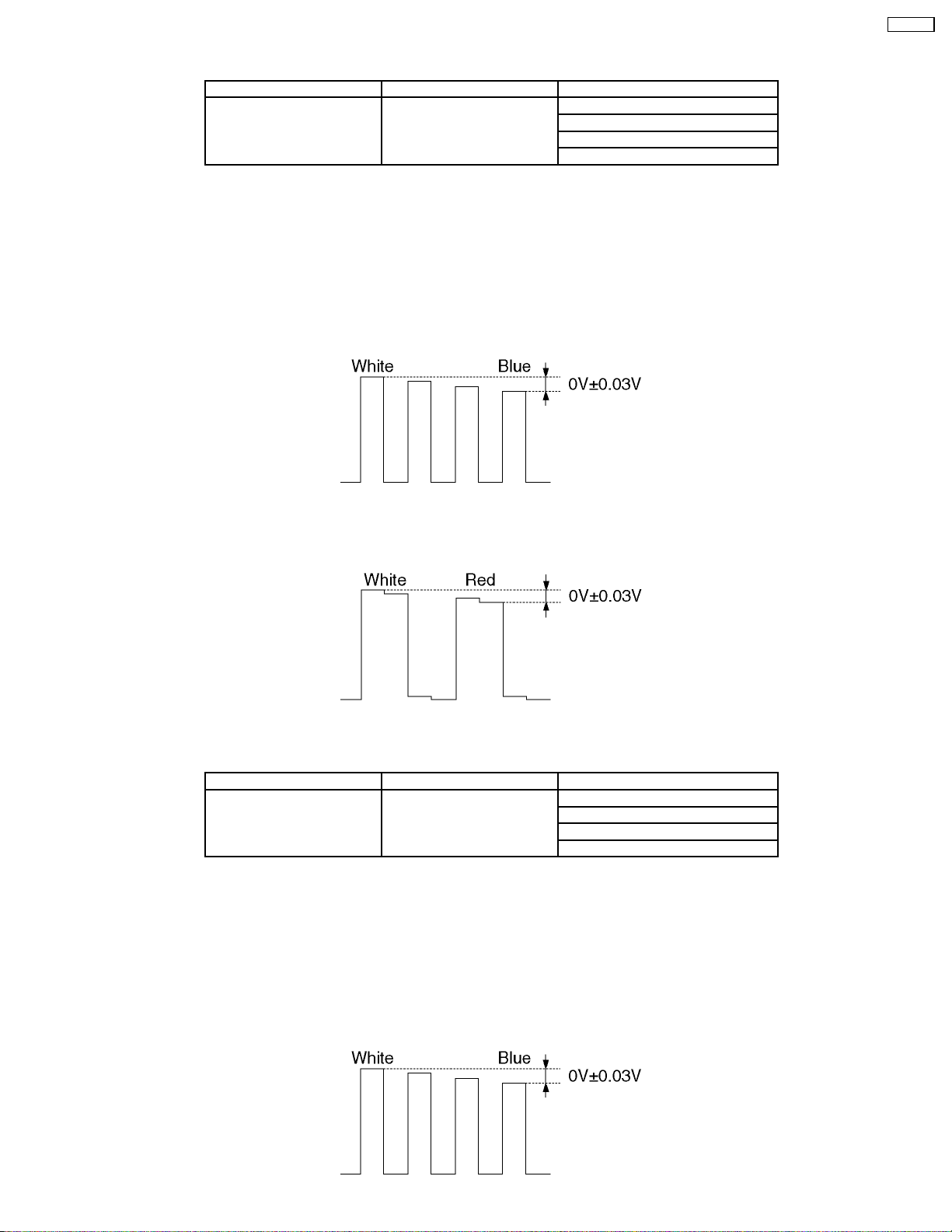
8.4.3. NTSC picture video (S terminal)
Measuring instrument Connection Mode
Remote control transmitter
Video signal
Oscilloscope
·
· Receive 100% color bar signal at video input 1 (S terminal).
· ·
·
· Enter the adjustment mode and adjust the amplitude level of each signal in the following steps.
· ·
1.Y signal
With [VOLUME+/-] buttons of the remote control transmitter, adjust the value appearing below YGAIN indication so that the
value below MAX indication becomes B8.
2.B-Y signal (TP238)
With [VOLUME+/-] buttons of the remote control transmitter, adjust the value appearing below B-Y indication so that the
amplitude (yellow-blue) at TP238 becomes 0±0.03V.
TP236~TP239 (GND) :R
TP237~TP239 (GND) :G
TP238~TP239 (GND) :B
ASPECT : 4:3
PIC MODE : STANDARD
BACK LIGHT : + 30
AI PICTURE : OFF
17
CT-L1400
3.R-Y signal (TP236)
With [VOLUME+/-] buttons of the remote control transmitter, adjust the value appearing below R-Y indication so that the
amplitude (white-red) at TP236 becomes 0±0.03V.
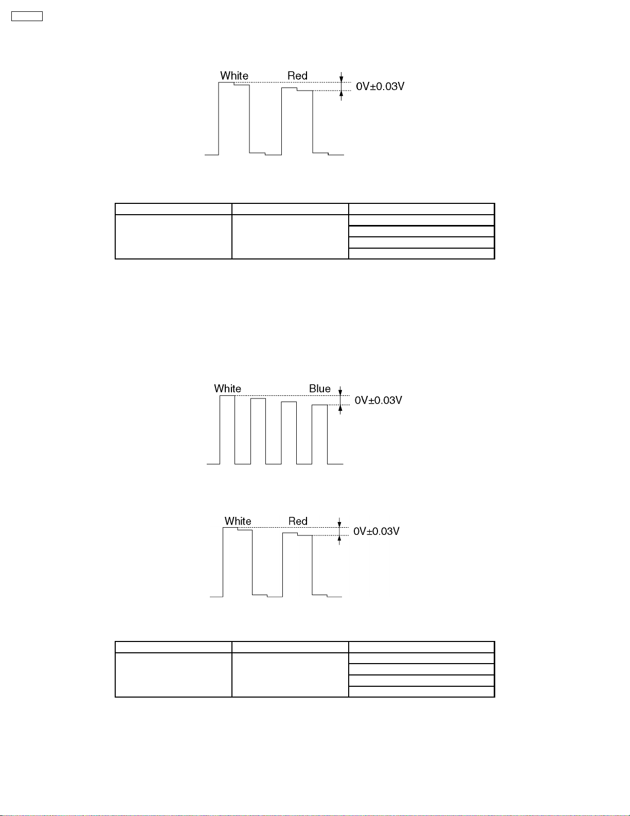
8.4.4. NTSC Component (525i) level adjustment
Measuring instrument Connection Mode
Remote control transmitter
525i signal
Oscilloscope
·
· Receive 100% color bar signal at video input 1 (S terminal).
· ·
·
· Enter the adjustment mode and adjust the amplitude level of each signal in the following steps.
· ·
1.Y signal
With [VOLUME+/-] buttons of the remote control transmitter, adjust the value appearing below YGAIN indication so that the
value below MAX indication becomes DC.
2.B-Y signal (TP238)
With [VOLUME+/-] buttons of the remote control transmitter, adjust the value appearing below B-Y indication so that the
amplitude (yellow-blue) at TP238 becomes 0±0.03V.
TP236~TP239 (GND) :R
TP237~TP239 (GND) :G
TP238~TP239 (GND) :B
ASPECT : 4:3
PIC MODE : STANDARD
BACK LIGHT : + 30
AI PICTURE : OFF
3.R-Y signal (TP236)
With [VOLUME+/-] buttons of the remote control transmitter, adjust the value appearing below R-Y indication so that the
amplitude (cyan-red) at TP236 becomes 0±0.03V.
8.4.5. NTSC Component (525p) level adjustment
Measuring instrument Connection Mode
Remote control transmitter
525p signal
Oscilloscope
·
· Receive 100% color bar signal at video input1 (S terminal).
· ·
·
· Enter the adjustment mode and adjust the amplitude level of each signal in the following steps.
· ·
1.Y signal
With [VOLUME+/-] buttons of the remote control transmitter, adjust the value appearing below YGAIN indication so that the
value below MAX indication becomes B8.
TP236~TP239 (GND) :R
TP237~TP239 (GND) :G
TP238~TP239 (GND) :B
ASPECT : 4:3
PIC MODE : STANDARD
BACK LIGHT : + 30
AI PICTURE : OFF
18

2.B-Y signal (TP238)
With [VOLUME+/-] buttons of the remote control transmitter, adjust the value appearing below B-Y indication so that the
amplitude (white-blue) at TP238 becomes 0±0.03V.
3.R-Y signal (TP236)
With [VOLUME+/-] buttons of the remote control transmitter, adjust the value appearing below R-Y indication so that the
amplitude (white-red) at TP236 becomes 0±0.03V.
8.5. Flicker Adjustment
CT-L1400
1.Enter the adjustment mode and select the " FLICKR".
2.Adjust the Flicker Adjustment until the flicker displayed on the screen is minimum.
Note:
Adjustment shall be done after it is made to overrun value of adjustment once as shown figure A.
Note:
Make the adjustment to look for the optimum point because the level of flicker doesn´t disappear on the screen completely as
shown figure A.
Figure A
19
CT-L1400
8.6. MTS Adjustment
Caution:
MTS adjustment shall be after the aging of 30 minutes or longer.
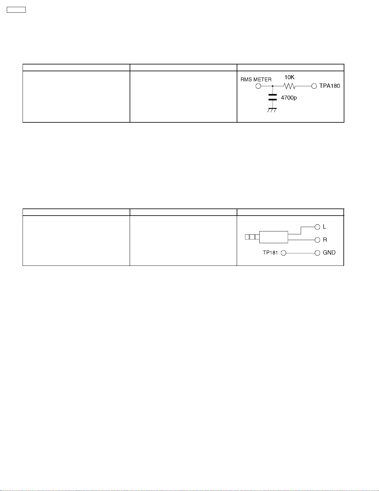
8.6.1. Input level Adjustment
Instrument name Connection Remarks
1.Filter jig
2.RF signal generator
3.RMS voltage meter
1.Apply following RF signal at Antenna input.
VIDEO : Flat field, 30 % modulation
AUDIO : 300 Hz, 100 % modulation, monaural
(70dB±5dB,759, P/S 10 dB)
Note:
Make sure 75 us PRE-EMPHASIS is off.
2.Adjust "MTSIN" data (Input level) until the RMS voltage meter indicates 106 mVrms ± 6 mVrms
TPA180 - GND (TP181)
RF ANT. INPUT
Filter jig
Filter jig
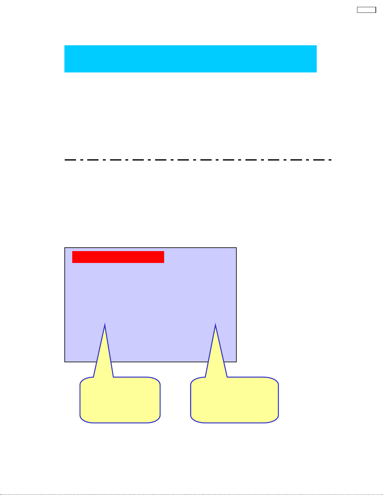
8.6.2. Stereo Separation Adjustment
Instrument name Connection Remarks
1.RF signal generator
2.Oscilloscope
3.Headphone jig
1.Select STEREO mode in the AUDIO Menu.
2.Set “Audio volume” DAC to “40”.
3.Apply following RF signal at Antenna input.
VIDEO : Flat field, 30% modulation
AUDIO : 300Hz, 30% modulation, STEREO (LEFT only)
(70dB ± 5dB, 75 9 OPEN, P/S 10dB)
Note:
After setting 30% modulation with PL SW and NR SW off, turn PL SW and NR SW on.
4.Adjust "SEPAL" data (Low-level separation) until the amplitude.
5.Apply following RF signal at Antenna input.
VIDEO : Flat field, 30% modulation
AUDIO : 3kHz, 30% modulation, STEREO (LEFT only)
(70dB ± 5dB, 759 OPEN, P/S 10dB)
Note:
After setting 30% modulation with PL SW and NR SW off, turn PL SW and NR SW on.
6.Adjust "SEPAH" data (High-level separation) until the amplitude of the waveform on the oscilloscope is minimum.
7.Repeat steps 3. to 6. until Low-level separation and High-level separation satisfy above-mentioned conditions.
Note:
The separation must be more than 20 dB at 300Hz and 3kHz.
RF ANT. INPUT
TPA150 - GND (TP181)
Headphone jig
20
9 Hotel Mode
Go into Hotel Mode:
CT-L1400
Hotel Mode
Change EEPROM Address
Back to Normal Mode:
Change EEPROM Address from 80 to 00.
Note : Hotel mode can not be cleared by SELFCHECK.
00EF
from 00 to80.
Hotel Mode Setting:
Hold the “VOLUME DOWN” button inside the door of unit and
press the “TV/VIDEO” button on the remote control three times within 1 seconds.
Exiting the Hotel Mode Setting:
Press “Power” button on the remote control or on the unit.
POWER ON SETTING
CH/VIDEO
VOLUME
VOLUME MAX
CH/VOLUME
124
3
40
OSD STOP DISPLAY
KEY STOP OPERATION
Item Selection:
Press “CH UP/DOWN”
buttonontheremote
control.
PATTARN1
ALL
Change Setting:
Press “VOL UP/DOWN”
button on the remote
control.
21

CT-L1400
POWER ON SETTING
DON’T:
CH:
VOLUME:
CH/VOLUME:
No setting
Set Channel number when turn on the unit.
Set Volume level when turn on the unit.
Set Channel number and Volume level when turn on the unit.
CH/VIDEO setting
For Channel number setting:
For VIDEO INPUT setting :
Press “VOL UP/DOWN”buttonontheremotecontrol.
Press “VTV/VIDEO” button on the remote control.
VOLUME setting
Press “VOL UP/DOWN” button on the remote control.
VOLUME MAX
To set the volume max level:
Press “VOL UP/DOWN” button on the remote control.
Note: On-screen value is changed normally from 0 to 63 after setting. But
maximum output sound level is limited according to this setting.
OSD STOP DISPLAY
ALL:
PATTERN1:
PATTERN2:
PATTERN3:
No ON-SCREEN display
Channel number and TV/Video status are displayed when changing
the channel or TV/Video.
ASPECT (4:3 / 16:9) is displayed when changing the ASPECT.
PATTERN1 and PATTERN2.
Channel number, TV/Video status and ASPECT are displayed when
changing the channel, TV/Video or Aspect.
KEY STOP OPERATION
ALL: All buttons on the unit (TV/VIDEO, VOL up/down, CH up/down) are
PATTERN1:
PATTERN2:
PATTERN3:
Note: All buttons on the remote control are effective in any KEY STOP
OPERATION setting.
Pressing VOL Down button on the unit for setting Hotel mode is effective.
not effective.
VOL up/down and CH up/down buttons on the unit are not effective.
Same as PATTERN1.
Same as PATTERN1.
22

Appendix:
Change address 00EF from 00 to 80
in Memory Edit Mode.
Entry to the Serviceman Mode:
Hold the “VOLUME DOWN” button inside the door of unit and
press the “RECALL” button on the remote control three times within 1 seconds.
Select main item OTP:
Press “1”or“2” button on the remote control.
Entry to the Memory Edit Mode / Some information indication:
press the “MUTE” button on the remote control for more than 3 seconds in OPT menu.
CT-L1400
Select ADDRESS “00EF”:
1. Press ”3” button on the remote control to change address.
Change DATA to “80”:
1. Press “VOLUME UP/DOWN” button to change data.
2. Press “6” button for 3 seconds to store the data.
TV unit go into Hotel Mode.
Exiting the Service Mode:
Press “Power” button on the remote control or on the unit.
23
 Loading...