

Panasonic CT32SX30E - DTV Operating Instructions Manual

Color Television
Operating Instructions
CT-32SX30
®
For assistance, please call: 1-800-211-PANA (7262) or
send e-mail to: consumerproducts@panasonic.com (USA only)
TQB2AA0338 00905
PRINTED IN USA
0338E Prod.fm Page 1 Wednesday, February 7, 2001 11:07 AM
0000000000000000000 0000000000000000000 0000000000000000000 00000000000000000000000 0000000000000000000 0000000000000000000 000000000
WA RNI NG : To reduce the risk of electric shock do n ot remove cover or back. No user-
serviceable parts inside. Refer servicing to qualified service personnel.
WARNING
0000000000000000 0000000000000000000 0000000000000000000 00000000000000000000000 00000000000
RISK OF ELECTRIC SHOCK
DO NOT OPEN
The lightning flash with arrow
head within a triangle is intended
to tell the user that parts inside
the product are a risk of electric
shock to persons.
The exclamation point within a
triangle is intended to tell the user
that important operating and
servicing instructions are in the
papers with the appliance.
WARNING: TO REDUCE THE RISK OF ELECTRIC SHOCK, DO NOT EXPOSE THIS APPARATUS
TO RAIN OR MOISTURE.
Certain audio features of this product are manufactured under a license from Desper Products, Inc.
Spatializer® and the circle-in-square device are trademarks owned by Desper Products, Inc.
Spatializer U.S. Patents are: 4,308,423; 4,355,203 and 5,412,731.

0338E Prod.fm Page 2 Wednesday, February 7, 2001 11:07 AM
T
ABLE OF CONTENTS
T able of Content s
Congratulations........................ ..... ..... .... ..... ..... .... ....3
Customer Record ........................ ....... ...... ....... ...... ...... .............3
Care and Cleaning ...................................................................3
Specifications ...........................................................................3
Installation.................................................................4
Television Location...................................................................4
Optional Cable Connections.....................................................4
AC Power Supply Cord ............................................................4
Cable / Antenna Connection ....................................................5
Optional Equipment Connections.............................................6
Additional Equipment Connections ..........................................9
Amplifier Connection (TO AUDIO AMP)...................................9
Program Out Connection (PROG OUT).................................10
Digital TV - Set-Top Box (DTV-STB)
or DVD Connection ................................................................10
Home Theater Connection ....................................................11
Picture In Picture (PIP) Operation.........................12
Split Screen Operation...........................................13
Roller Guide Menu™ .............................................. 14
Basic Navigation.....................................................................14
Remote Control Guide............................................................14
Roller Guide Feature Chart....................................15
Special Features.....................................................18
Menu Languages....................................................................18
Prog Chan (Program Channels).............................................18
Closed Captioning..................................................................19
Geomagnetic Correction ........................................................20
Picture Adjustments ...............................................................21
Favorite Channels and Captions............................................22
Dolby Center Mode & Fixed Audio Out ..................................22
Lock........................................................................................23
Sleep Timer..................................................... ...... ...... ....... ....24
Timer 1 and Timer 2...............................................................24
Troubleshooting Chart...........................................25
Read these instructions completely before operating television.
Contents are subject to change without notice or obligation.
Copyright 2000 by Matsushita Electric Corporation of America. A ll rights reserved.
Unauthorized copying and distribution is a violation of law.
2
0338E Prod.fm Page 3 Wednesday, February 7, 2001 11:07 AM
Congratulations
Your new Panasonic Tau television is designed to provide state-of-the-art picture quality and
features an innovative PureFlat
elegant styling is designed to give you many years of enjoyment. It was thoroughly tested and
tuned at the factory for best performance.
Customer Record
The model and serial number of this product are located on the back of the television. You
should note the model and serial number in the space provided and retain as a permanent
record of your purchase. This will aid in identification in the event of theft or loss. Product
registration for U.S. customers is available at www.prodreg.com/panasonic.
Model
Number
Serial
Number
C
ONGRATULATIONS
TM
picture tube. The new silver-gray cabinet with compact,
Care and Cleaning
Screen (Turn TV Off)
Cabinet and Remote Control
r For cabinets and remote control, use a soft cloth dampened with water or a mild detergent
r Do not use benzene, thinner or other petroleum based products.
Specifications
Power Source
CT-32SX30 (2.9A)
• Use a mild soap solution or window cleaner with a sof t cl ean cloth. DO NOT USE
ABRASIVE CLEANERS.
• Avoid excessive moisture and wipe dry.
Note: Do not spray any type of cleaning fluid directly on the screen.
solution. Avoid excessive moisture and wipe dry.
120V AC, 60Hz
Channel Capability - 181 VHF-12; UHF-56; Cable-125
Video Input Jacks 1Vp-p, 75 Ohm, Phono Jack Type
Audio Input Jacks 500mV RMS 47K Ohm
Video Output Jack 1Vp-p, 75 Ohm, Phono Jack Type
Audio Output Jacks 0-2.0V RMS 4.7K Ohm
Component Input 75 Ohm, Phono Jack Type
S-Video Input Jacks S-Video (Y-C) Connector
Specifications are subject to change without notice or obligation.
3

0338E Prod.fm Page 4 Wednesday, February 7, 2001 11:07 AM
I
NSTALLATION
Installation
Television Location
This unit is intended to be used with an optional stand or entertainment center. Consult your
dealer for available options.
r Avoid excess ive sunlight or bright lights, including reflections.
r Keep away from excessive heat or moisture. Inadequate ventilation may cause internal
component failure.
r Fluorescent lighting may reduce remote control transmitting range.
r Keep away from magnetic equipment, including motors, fans and external speakers.
CAUTION: Use this television receiver only with the cart, stand, tripod,
bracket, or table specified by the manufacturer, or sold with the apparatus.
When a cart is used, use caution when moving the cart/apparatus combination
to avoid injury from tip-over. In order to avoid injury to children, never place your
television receiver on a piece of furniture that is capable of being tilted by a child
leaning on it, pulling on it, standing on it, or climbing on it.
CT-32SX30:
CAUTION:
Use with other carts (or stands) is capable of resulting in instability causing possible
injury.
This television receiver for use only with PANASONIC TY-32HX40P stand.
Optional Cable Connections
Shielded audio and video cables should be used between components. For best results:
r Use 75-ohm coaxial shielded cables.
r Use appropriate input and output connectors that match your component connectors.
r Avoid long cables to minimize interference.
AC Power Supply Cord
CAUTION: TO PREVENT ELECTRIC SHOCK MATCH WIDE BLADE OF
PLUG TO WIDE SLOT OF AC OUTLET AND FULLY INSERT. DO NOT
USE A PLUG WITH A RECEPTACLE OR OTHER OUTLET UNLESS THE
BLADE CAN BE FULLY INSERTED TO PREVENT BLADE EXPOSURE.
PROTECT POWER CORDS FROM BEING WALKED ON, ROLLED OVER, CRIMPED, BENT
OR PINCHED, PARTICULARLY AT PLUGS, CONVENIENCE RECEPTACLES, AND THE
POINT WHERE THEY EXIT FROM THE APPARATUS.
Polarized plug
4
0338E Prod.fm Page 5 Wednesday, February 7, 2001 11:07 AM
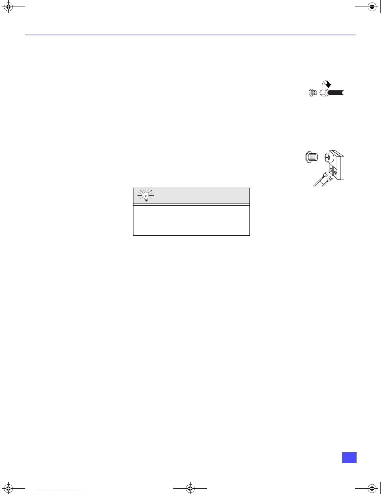
Cable / Antenna Connection
For proper reception, either a cable or antenna con nection is required.
I
NSTALLATION
Cable Connection
Connect the cable supplied by your local cable company to ANT1
connection on ba ck of t elevi sion. Se lect c able m ode a nd ANT1 in SET UP
menu under Prog Chan (Program Channels).
Note: A cable converter box may be required for proper
reception. Check with your local cable company for
compatibility requirements.
Antenna Connection
• For proper reception of VHF/UHF channels, an external
antenna is required. For best reception, an outdoor
antenna is recommended.
• Connect home antenna to ANT1 connection on back of
television. Select TV mode and ANT1 in the SET UP menu
under Prog Chan.
Cable Preset
Cable Mode is preset at the factory.
Antenna users must change to TV mode and
select ANT1 in the Set Up Menu under Prog
Chan.
Incoming Cable from
Cable Company
75 Ohm VHF/UHF
on back of TV
Incoming Cable from
Home Antenna
5
0338E Prod.fm Page 6 Wednesday, February 7, 2001 11:07 AM
I
NSTALLATION
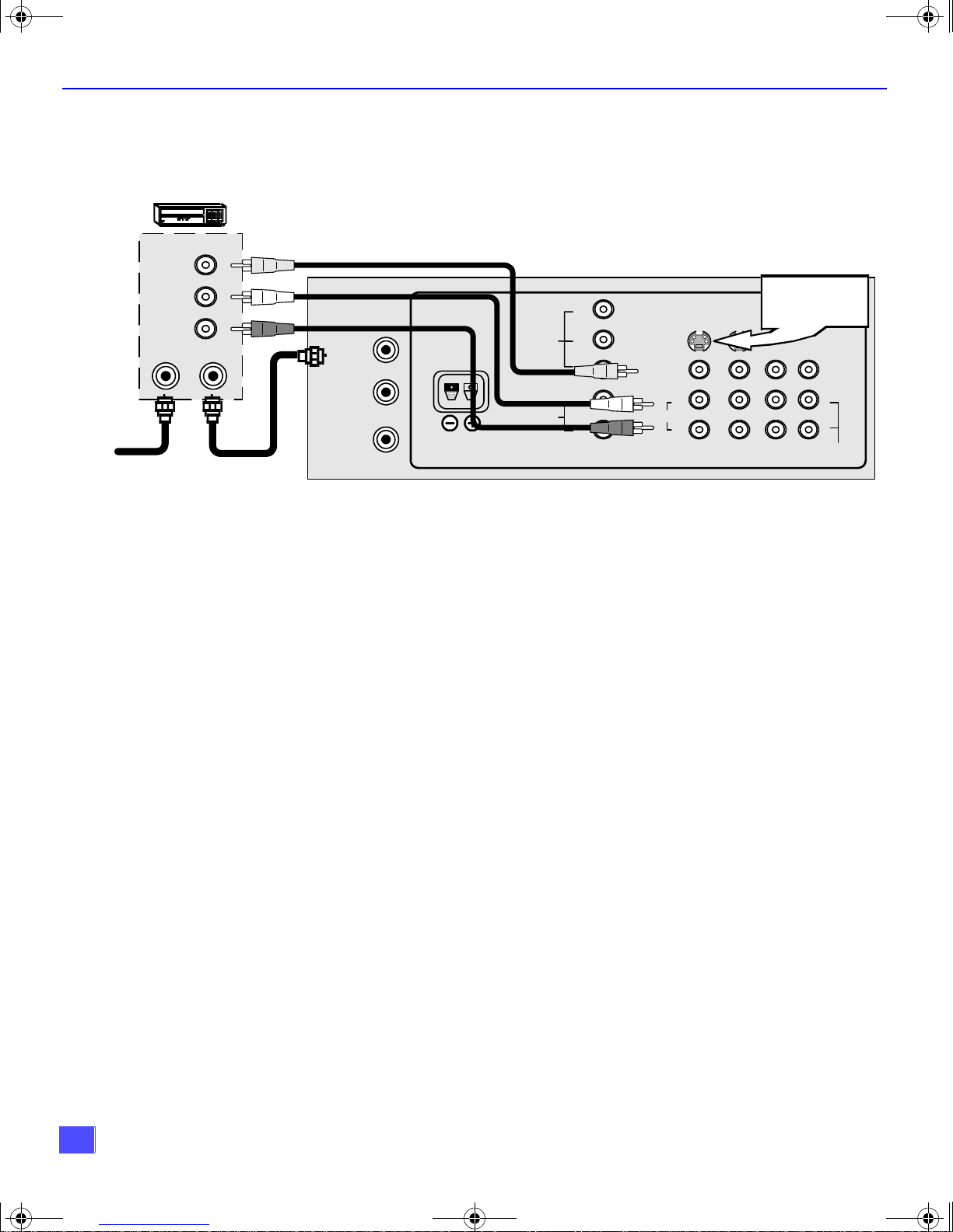
Optional Equipment Connections
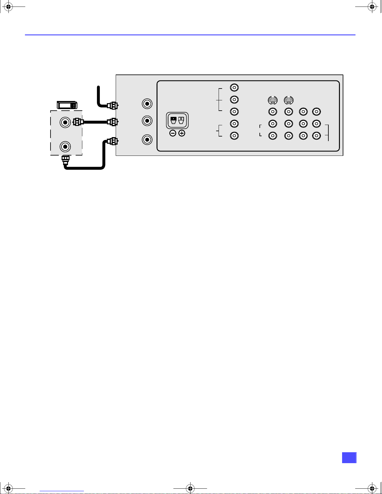
VCR Connection
Follow this diagram when connecting your television to a VCR only.
VCR
VIDEO OUT
L
AUDIO OUT
R
ANT 1
SPLIT OUT
ANT 2
Incoming
Cable
ANT IN
ANT OUT
CABLES NOT SUPPLIED
CENTER CHANNEL
INPUT
CONNECTIONS ON BACK OF TV
Y
P
VIDEO
AUDIO
COM PON ENT VIDEO INPUT
B
P
R
L
R
SVIDEO
VIDEO
AUDIO
Use either the
S- Vi deo or V ideo
connection.
PROG
OUT
L
R
INP UT1INP UT2INP UT3TO AUDIO
L
R
AMP
Note: The remote control must be programmed with supplied codes to operate the
VCR. See Programming the Remote Control in the Remote Control Quick
Reference Guide.
Viewing a television program
Procedure
1. Select ANT1 in the SET UP menu under Prog Chan (Program Channels).
2. Tune the television to the television program you want to view.
Viewing a video
Procedure
1. Select ANT1 in the SET UP menu under Prog Chan.
2. Press the TV/VIDEO button on the remote control to select the video input (VIDEO 1,
VIDEO 2, etc.) connected to your VCR.
3. Begin the vi deo.
Recording a television program
Procedure
r Option A (Recording and viewing the same program)
1. Select ANT1 in the SET UP menu under Prog Chan.
2. Tune the television to Channel 3 or 4, depending on your VCR.
3. Using the VCR, tune to the television program you want to record.
4. Begin recording.
r Option B (Recording one program while viewing another program).
1. Select ANT1 in the SET UP menu under Prog Chan.
2. Press the TV/VIDEO button on the remote control to select the video input (VIDEO 1,
VIDEO 2, etc.) connected to your VCR.
3. Using the VCR, tune to the television program you want to record.
4. Begin recording.
5. Press the TV/VIDEO button on the remote control to switch back to TV mode.
6. Tune the television to the television program you want to view.
6
0338E Prod.fm Page 7 Wednesday, February 7, 2001 11:07 AM
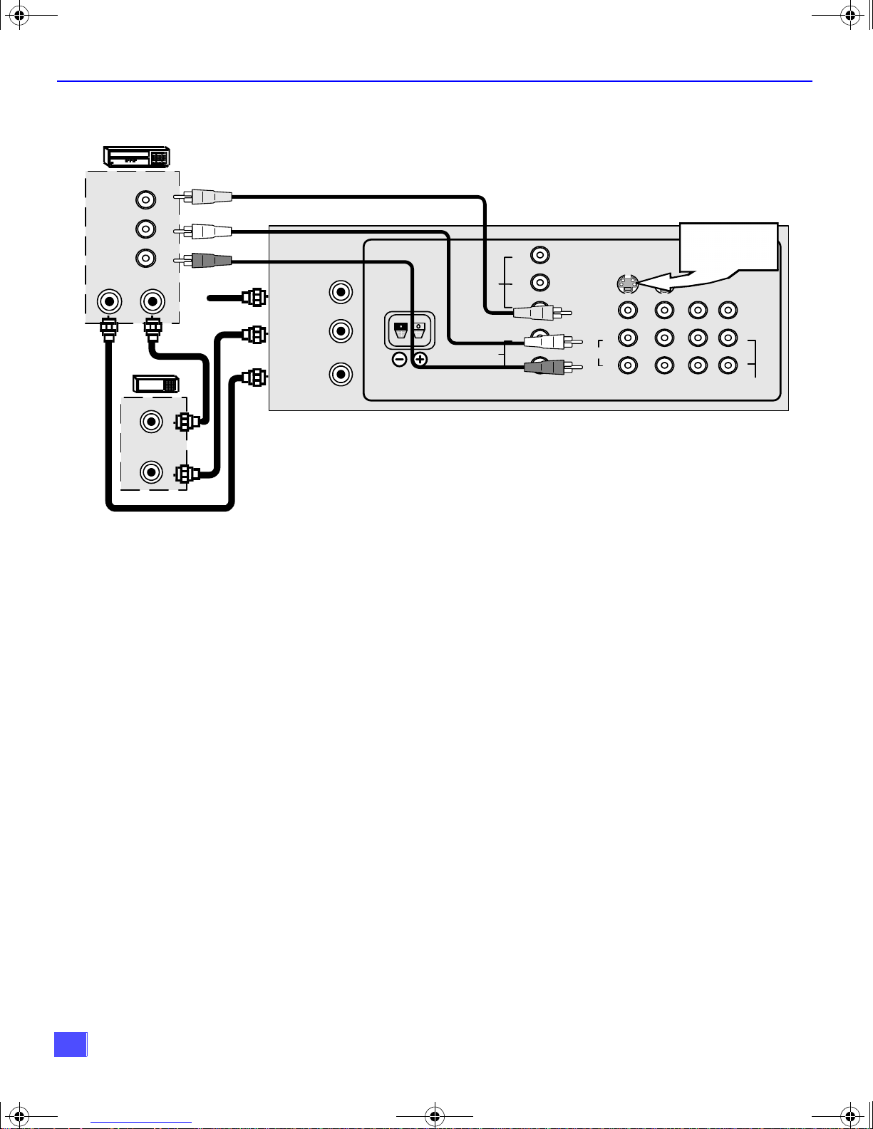
Cable Box Connection
Follow this diagram when connecting your television to a cable box only.
Inco ming
Cable
CABLE BOX
ANT 1
ANT IN
SPLIT OUT
ANT OUT
ANT 2
Note: The remote control must be program med with supplied codes to operate the
Viewing a premium (scrambled) cable channel
Procedure
1. Select ANT2 in the SET UP menu under Prog Chan (Program Channels).
2. Tune the television to Channel 3 or 4.
3. Using the cable box, tune to the premium cable channel you want to view.
Note: To use special features such as Favorite Channels and Channel Captions
I
NSTALLATION
CONNECTIONS ON BACK OF TV
Y
CENTER CHANNEL
INPUT
P
VIDEO
AUDIO
COMPO NEN T VIDEO INPUT
B
P
R
L
R
SVIDEO
VIDEO
AUDIO
L
R
INP UT1INP UT2INP UT3TO AUD IO
PROG
OUT
L
R
AMP
cable box. See Programming the Remote Control in the Remote Control
Quick Reference Guide.
(see Special Features section for more information), ANT1 must be selected
in the SET UP menu under Prog Chan.
7
0338E Prod.fm Page 8 Wednesday, February 7, 2001 11:07 AM
I
NSTALLATION
VCR and Cable Box Connection
Follow this diagram when connecting your television to both a VCR and a cable box.
VCR
VIDEO OUT
AUDIO OUT
ANT OUT
L
R
ANT IN
CABLE BOX
ANT OUT
ANT IN
CABLES NOT SUPPLIED
Incoming Cable
ANT 1
SPLIT OUT
ANT 2
CENTER CHANNEL
INPUT
VIDEO
AUDIO
COMPO N ENT VIDEO INPUT
CONNECTIONS ON BACK OF TV
Y
P
B
P
R
L
R
SVIDEO
VIDEO
L
AUDIO
R
IN P UT1INP UT2INP UT3TO AUDIO
Use either the
S- Vi deo or V ideo
connection.
PROG
Note: The remote control must be programmed with supplied codes to operate the
VCR and cable box. See Programming the Remote Control in the Remote
Control Quick Reference Guide.
Viewing a premium (scrambled) cable channel
Procedure
1. Select ANT2 in the SET UP menu under Prog Chan (Program Channels).
2. Tune the television to Channel 3.
3. Using the cable box, tune to the premium cable channel you want to view.
Note: To use special features such as Favorite Channels and Channel Captions
(see Special Features section for more information), ANT1 must be selected
in the SET UP menu under Prog Chan.
Recording a premium (scrambled) cable channel
Procedure
1. Select ANT2 in the SET UP menu under Prog Chan.
2. Press the TV/VIDEO button on the remote control to select the video input (VIDEO 1,
VIDEO 2, etc.) connected to your VCR.
3. Turn the VCR ON.
4. Tune the VCR to Channel 3 or 4, depending on the switch setting on the back of VCR.
5. Using your cable box, tune to the premium cable channel you want to record.
6. Begin recording.
Note: To view a different channel while recording:
• Select ANT1 in the SET UP menu under Prog Chan.
• Press the TV/VIDEO button on the remote control to TV mode.
• Tune the television to a television program (except another premium cable
channel).
OUT
L
R
AMP
8
0338E Prod.fm Page 9 Wednesday, February 7, 2001 11:07 AM
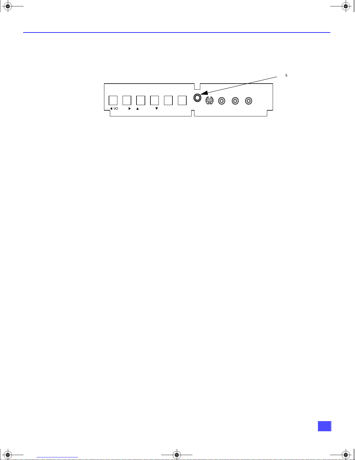
Additional Equipment Connections
Push to open the front panel of the television to use the Audio/Video input jacks for optional
equipment. Press the TV/VIDEO button to select VIDEO 4 input mode.
I
NSTALLATION
Jack used for 1/8”
headphone plug
t
VOLUME
CONNECTIONS ON FRONT OF TV
p
CHANNEL
u
ACTION TV/VIDEO
q
HPJ
S-VIDEO
VIDEO L-AUDIO-R
INPUT 4
A second VCR, a video disc player, video game equipment and DSS equipment can also be
connected to the video inputs. See the optional equipment manual for details.
Procedure
1. Connect equipment to rear or front Audio/Video input jacks.
2. Select the corresponding video input by pressing TV/VIDEO button.
3. Operate optional equipment as instructed in equipment manual.
Note: The S-VIDEO connection provides higher quality picture. It overrides other
VIDEO connections. Use INPUT 4, AUDIO L and R with S-VIDEO
connection.
IMPORTANT INFORMATION REGARDING USE OF VIDEO GAMES,
COMPUTERS, DSS OR OTHER FIXED IMAGE DISPLAYS.
The extended use of fixed image program material can cause a permanent “shadow image” on
the picture tube. This background image is viewable on normal programs in the form of a
stationary fixed image. This type of irreversible picture tube deterioration can be limited by
observing the following steps:
A. Reduce the brightness/contrast setting to a minimum viewing level.
B. Do not display the fixed image for extended periods of time.
C. Turn the power off when not in actual use.
Note: The marking or retained image on the picture tube resulting from fixed image
use is not an operati ng defect and as suc h is not co vered by War ranty. This
product is not designed to display fixed image patterns for extended periods
of time.
Amplifier Connection (TO AUDIO AMP)
To listen through a separate stereo system, connect an external audio amplifier TO AUDIO
AMP outputs on back of television.
Note: TO AUDIO AMP term in als c ann ot b e c onn ec ted dire ctly to external speakers.
Audio Adjustments
1. Select SPEAKERS ON located in the onscreen AUDIO menu.
2. Set amplifier volume to minimum.
3. Adjust television volume to desired level.
4. Adjust amplifier volume to match the television.
5. Select SPEAKERS OFF & VARIABLE AUDIO OUT from AUDIO menu.
6. Volume, mute, bass, treble and balance are now controlled through the television.
Note: Select SPEAKERS OFF & FIXED AUDIO OUT to control audio functions
through the external amplifier.
9
0338E Prod.fm Page 10 Wednesday, February 7, 2001 11:07 AM
I
NSTALLATION
Program Out Connection (PROG OUT)
To use the television audio and video with optional equipment, connect the PROG OUT and TO
AUDIO AMP connections on the back of the television.
Procedure
1. Connect optional equipment to PROG OUT and TO AUDIO AMP terminals.
2. PROG OUT terminal display is the same as onscreen display.
3. See optional equipment manual for further instructions for recording and monitoring.
Digital TV - Set-Top Box (DTV- STB ) or DVD Con nection
Use this diagram to connect the Panasonic DTV-STB (Digital TV-Set-Top Box) or
DVD Player to the back of your TV. Press TV/VIDEO button to select Component Input.
TERMINALS ON BACK OF DTV-STB OR DVD PLAYER
R-A U D IO-L
DIGITAL OUTPUT
Y
PBP
R
R-AUDIO-L VIDEO
NTSC OUTPUT
CABLES NOT SUPPLIED
S-VIDEO
Notes:
r There are three video inputs, Y, PB, and PR. Separate component color inputs provide
luminance and color separation. Use the L (left) and R (right) audio inputs.
r Select DTV - STB to 480i output mode. TV set can receive 480i signal only.
ANT 1
SPLIT OUT
ANT 2
COMPO NEN T VIDEO INPUT TERMINALS ON BACK O F TV
CENTER CHANNEL
INPUT
Y
P
VIDEO
AUDIO
COMPO NEN T VIDEO INPUT
B
P
R
L
R
SVIDEO
VIDEO
AUDIO
PROG
OUT
L
R
INPUT1INP UT2INP UT3TO AUDIO
L
R
AMP
10
0338E Prod.fm Page 11 Wednesday, February 7, 2001 11:07 AM
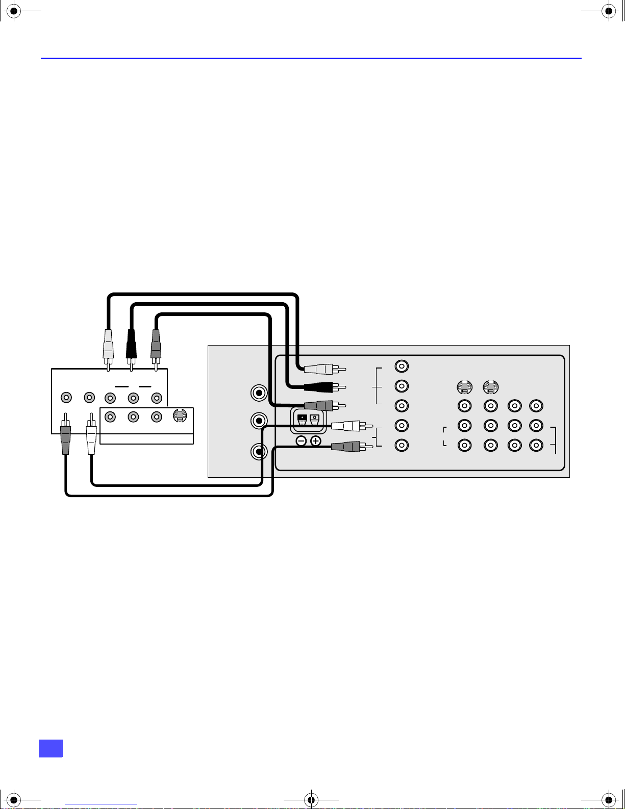
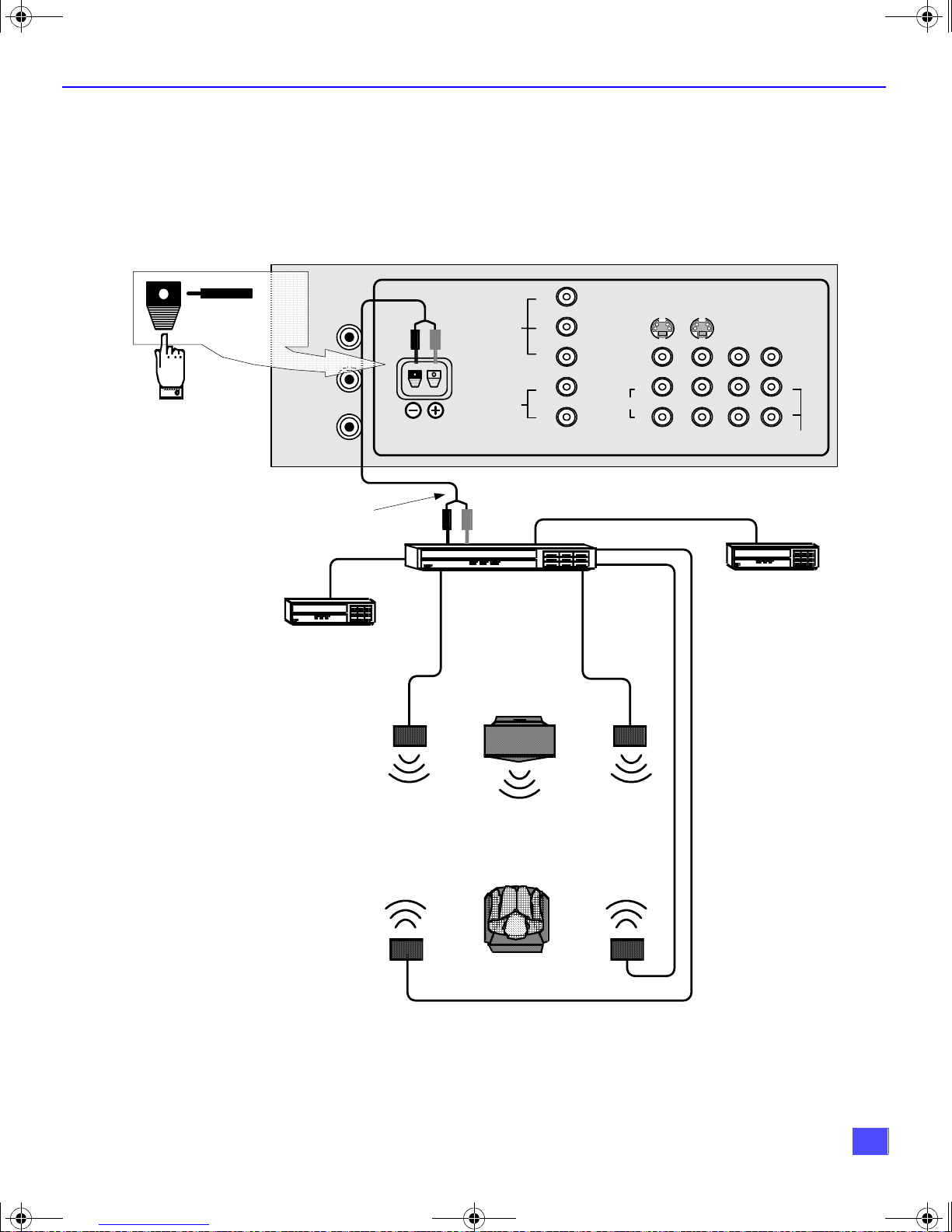
Home Theater Connection
Your television’s intern al speakers can be connected as the center channel for a surround sound
home theater system. Connect a surround sound amplifier (center channel speaker output) to
CENTER CHANNEL INPUT on the back of the t elevision, as shown. DOLBY* CE NTER MODE &
FIXED AUDIO OUT must be selected in the AUDIO Roller Guide Menu™** under SPEAKERS.
ANT 1
SPLIT OUT
(1). Push and hold
down button.
(2). Ins ert b a re wire
into hole and
release button.
ANT 2
CENTER CHANNEL
INPUT
CONNECTIONS ON BACK OF TV
Y
P
VIDEO
AUDIO
COMPO NEN T VIDEO INPUT
B
P
R
L
R
SVIDEO
VIDEO
L
AUDIO
R
INP UT1INP UT2INP UT3TO AUD IO
I
NSTALLATION
PROG
OUT
L
R
AMP
CENTER CHANNEL
SPEAKER OUTPUT
Video
component
Left Front
Speaker
Left Rear
Surround
Speaker
Surround Amplifier
TV
TV Speakers
Center Channel
VCR
Right Front
Speaker
Right Rear
Surround
Speaker
*Manufactured under license from Dolby Laboratories. “Dolby”, “Dolby Digital”, “Pro Logic” and the double-D symbol are trademarks
of Dolby Laboratories.
**US Patent Pending
Listener
11
0338E Prod.fm Page 12 Wednesday, February 7, 2001 11:07 AM
P
ICTURE IN PICTURE
(PIP) O
PERATION
Picture in Picture (PIP ) Operation
This television includes a two-tuner Picture In Picture (PIP) feature. This allows you to watch
two (2) live broadcasts at the same time with or without an external video source such as a
VCR, cable box, etc.
Basic PIP Operation
Procedure
Press the PIP button on the remote control to display the
Note: The audio is from the Main Picture only.
1. Choose channels for the
up/down buttons.
2. Choose channels for the
buttons or by using the numeric keypad.
PIP
frame ons c reen.
PIP
frame by pressing the remote control PIP CHANNEL
Main Picture
by pressing the remote control CH up/down
SWAP Button
PIP Operation with a Cable Box
Procedure
r To view premium (scrambled) cable channels through your cable box in the
Note: Use this procedure if you want to watch premium cable channels in the Main
Picture while viewing a television program or video in the PIP
1. Select ANT2 in the SET UP menu under Prog Chan (Program Channels).
2. Tune television to Channel 3.
3. Press the PIP button on the remote control to display the
Note: The audio is from the Main Picture only.
4. Verify the cable box is ON.
5. Choose channels for the
6. Choose channels for the
and using the PIP CHANNEL up/down buttons.
Note: Swap is not available when using the cable box to tune channels. If your
cable box has a video output, it can be connected to the televisi on to allow
you to use all PIP func tions. See the eq uipme nt man ual for m ore informa tio n.
(Tune the PIP to the video input connected to the cable box).
The SWAP button switches the PIP and Main
Picture source. Press the RECALL button for
onscreen PIP and Main Picture source status.
PIP
Main Picture
PIP
frame by pressing the TV button on the remote control
by tuning the cable box.
Main Pictur e
frame
frame ons c reen.
:
.
12
0338E Prod.fm Page 13 Wednesday, February 7, 2001 11:07 AM
Split Screen Operation
This feature lets you watch two different channels side by side with or without an external video
source. The audio is from the Main picture only (left side).
Basic SPLIT Operation
Procedure
1. Select ANT1 in the SET UP menu under Prog Chan (Program Channels).
SPLIT/SIZE
2. Press the button on the remote control to display the
PLAY
MAIN SPLIT
S
PLIT SCREEN OPERATION
SPLIT
screen.
Note: The audio is from the Main Picture only.
3. Choose channels for the
up/down buttons.
4. Choose channels for the
buttons or by using the numeric keypad.
5. The SWAP button switches the SPLIT and MAIN Picture source. Press RECALL
button for onscreen SPLIT and Main Picture source status.
SPLIT Picture
Main Picture
by pressing the remote control PIP CHANNEL
by pressing the remote control CH up/down
Note: SPLIT Screen does not show the picture of ANT2 connection.
13
0338E Prod.fm Page 14 Wednesday, February 7, 2001 11:07 AM
R
OLLER GUIDE MENU
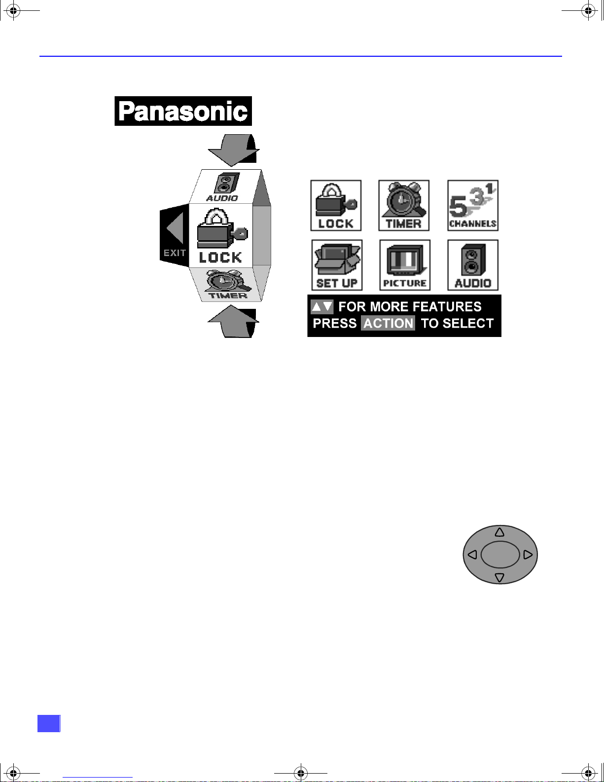
Roller Guide Menu
ROLLER GUIDE MENU SELECTIONS
Basic Navigation
Procedure
r Press the ACTION button in the middle of the large blue button on the remote control to
display the Roller Guide Menu.
r Press the CH up/down buttons to rotate the Roller Guide.
r Press the left VOL button to exit the Roller Guide Menu.
Navigation in the Roller Guide
Procedure
r Press the ACTION button to select main menu items.
r Press the CH up/down buttons to highlight submenus
r Press the VOL buttons to select and adjust features.
r Press the ACTION button to return to submenus.
Remote Control Guide
The Remote Control Quick Reference Guide is located within the package provided with
this television.
Note: Be careful to press the ACTION button in the middle of the button. If you do
not press in the middle of the button, the channel or volume keys may be
activated.
CH
ACTION
CH
VOL VOL
14

0338E Prod.fm Page 15 Wednesday, February 7, 2001 11:07 AM
Roller Guide Feature Chart (Cont.)
M
ENU
R
OLLER GUIDE FEATURE CHART
D
ESCRIPTION
SET UP
IDIOMA/LANGUE
(Languages)
PROG CHAN
(Program Channels)
CC
(Closed Captioning)
OTHER ADJ
(Adjustments)
r
MODE - Select English, Spanish or French menu.
r
MODE - Selec t TV or Cable mode. See Installation
section in Ma nual.
r
ANTENNA - Select ANT1 or AN T2. See Installat i on
section in manual.
r
AUTO PROGRAM - Automatically program
channels having a signal into memory.
r
MANUAL PROGRAM - Manually add or delete
channels from memory.
r
CC ON MUTE - Activate C1-C4 for Closed
Captioning display when the remote MUTE button
is pressed.
r
CC MODE - Select T1-T4 or C1-C4 for Closed
Captioning, progra m guid es, and othe r in format ion.
r
AUTO POWER ON - Select SET to power up the
TV at the same time as the Cable Box or other
components or select OFF.
r
GEOMAGNETIC CORR - Special adjustment
option that compensates for the earth’s
geomagnetic field. Adjustment may be required for
geomagnetic fields in the area.
PICTURE
VIDEO ADJ
(Adjustments)
OTHER ADJ.
(Adjustments)
r
COLOR - Adjust desired color intensity .
r
TINT - Adjust natural flesh tones.
r
BRIGHTNESS - Adjust dark areas for crisp detail.
r
PICTURE - Adjust white areas of picture.
r
SHARPNESS - Adjust clarity of outline detail.
r
NORMAL - Reset all picture adjustments to factory
default settings.
r
COLOR TEMP - Adjust white balance to COOL
(blue), WARM (red) or NORMAL.
r
NATURAL COLOR - Expands the color
reproduction range resulting in vivid pictures with
natural color gradation and highly delicate hues.
r
VIDEO NR - Reduces noise in the channel,
commonly called snow. Remains off when
receiving strong signal.
r
3D Y/C FILTER - Minimize noise and cross color in
the picture.
r
ASPECT - Select picture size (ratio) to match
programming format.
15

0338E Prod.fm Page 16 Wednesday, February 7, 2001 11:07 AM
R
OLLER GUIDE FEATURE CHART
Roller Guide Feature Chart (Cont.)
M
ENU
FAVORITES
CAPTION
D
ESCRIPTION
CHANNELS
r
CHANNEL SCAN - Select FAV (16 favorites) or
ALL channels to scan channels using the CH up/
down buttons.
r
PRESET CAPTION - Assign channel numbers to
preset popular television stations.
r
MANUAL CAPTION - Enter channel numbers and
captions manually.
r
INPUT LABEL - Label video connections to display
optional equipment.
LOCK
MODE
HOW LONG?
CLOCK SET
SLEEP
TIMER 1
TIMER 2
r
Lock All, Channels or Game with a secret code.
r
Select the period of time (12, 24, 48 hours or
ALWAYS) for your option to be locked.
TIMER
r
Set the time and the day of the week. (Time will
display onscreen after turning on the television,
pressing the RECALL button or changing
channels).
r
Set timer to turn off television in 30, 60 or
90 minutes. Select NO to turn timer off.
r
Set one or both timers to automatically turn
television on and off at selected times, on selected
channels, and on selected days. (Clock must be
set to use Timer features).
16
 Loading...