

Panasonic CT-32G31 Owner’s Manual
Color Television
Operating Instructions
®
Read these instructions completely before operating this set.
Contents subject to change without notice or obligation.
Copyright 1995 by Matsushita Electric Corporation of America.
Allrights reserved. Unauthorized copying and distribution is a violation of law.
CT-32G31
Printed In USA
TQB2AA0019-1
Safety Instructions
WARNING A
WARNING: To reduce the risk ofelectric shockdo not remove cover or back. No
user-serviceable parts inside. Refer servicing to qualified service personnel.
The lightning flash with ar-
is intended to tell the user
_1= row-head within a triangle _1=
that parts inside the product
are a riskofelectric shockto
persons,
The exclamation point within
a triangle is intended to tell
the user that important oper-
ating and servicing instruc-
tions are in the papers with
the appliance.
Note To CATV System Installer: This reminder is provided to call the CATV system installer's attention to Article
820-40 ofthe NEC that provides guidelines for proper grounding and, in particular, specifies that the cable ground shall be
connected to the grounding system of the building, as close to the point of cable entry as practical.
Safety Instructions For Television Receivers
1. Read and apply the operating instructions provided with your television receiver.
2. Read all of the instructionsgiven here and retain them for later use.
3. Unplug this television receiver from the wall outlet before cleaning. Do notuse liquid or aerosol cleaners. Use a damp
cloth for cleaning.
4. Do not use attachments not recommended by the television receiver manufacturer as they may cause hazards.
5. Do not use this television receiver near water. For example: Avoid placing it near a bathtub, washbowl, kitchen sink, or
laundry tub, in a wet basement, or near a swimming pool, etc.
6. Do not place this television receiver on an unstable cart, stand, or table. The television receiver may fall, causing serious
injury to a child or adult, and serious damage to the appliance. Use only with a cart or stand recommended by the
manufacturer, or sold with the television receiver. Wall or shelf mounting shouldfollow the manufacturer's instructions,
and should use a mounting kit approved by the manufacturer.
6A. An appliance and cart combination should be moved with care. Quick stops, excessive force, and
uneven surfaces may cause the appliance and cart combination to overturn.
7. Slots and openings in the cabinet and the back or bottom are provided for ventilation, and to insure
reliable operation of the television receiver and to protect it from overheating. These openings must not be blocked or
covered. The openings should never be blocked by placing the television receiver on a bed, sofa, rug or other similar
surface. This television receiver should never be placed near or over a radiator or heat register. This television receiver
should not be placed in a built-in installation such as a bookcase unless proper ventilation is provided.
8. Operate only from the type of power source indicated on the marking label. If you are not sure of the type of power
supplied to your home consult your television dealer or local power company. For television receivers designed to
operate from battery power, refer to the operating instructions.
9. This te_evisi_n receiver is equ_pped with a p__arized a_ternating-current line p_ug(ap_ughaving _ne b_adewider than the
other). This plug will fit into the power outlet only one way. This is a safety feature. Ifyou are unable to insert the plug
fully into the outlet, try reversing the plug. If
the plug should still fail to fit, contact your
electrician to replace your obsolete outlet. Do
not defeat the safety purpose of the polarized
plug.
10. Do not allow anything to rest on the power
cord. Do not locate this television receiver
where the cord will be abused by persons
walking on it.
11. Follow all warnings and instructions marked
on the television receiver.
12. Do not overload wall outlets and extension
cords as this can result in fire or electric
shock.
13. Never push objects of any kind into this
television receiver through cabinet slots as
they may touch dangerous voltage points or
short out parts that could result in a fire or
electric shock. Never spill liquid of any kind on
the television receiver.
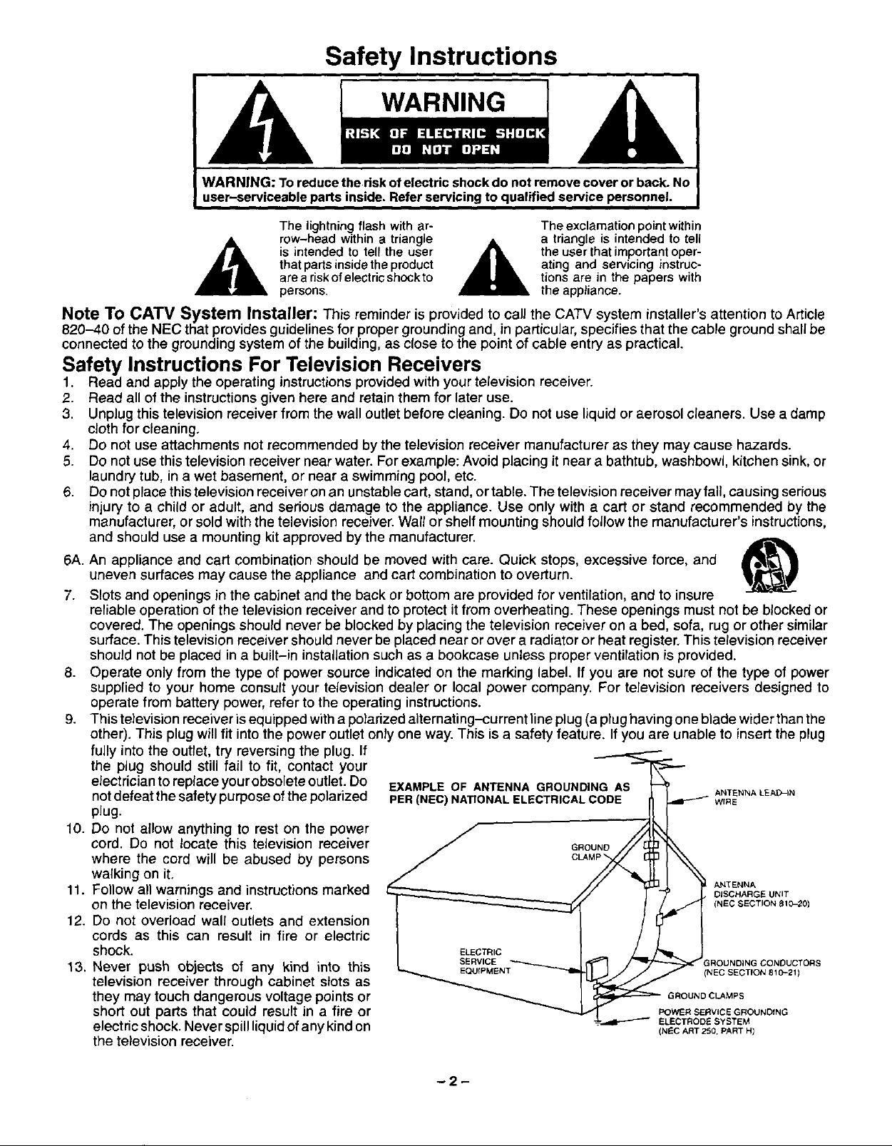
EXAMPLE OF ANTENNA GROUNDING AS
PER (NEC) NATIONAL ELECTRICAL CODE
__ ANTENNA
GROUND l _S
ELECTRIC
SERVICE ROUNDING CONDUCTORS
_ (NES SECTION 810-201
_ ELECTRODE SYSTEM
GROUND CLAMPS
POWER SERVICE GROUNDING
(N_C ART 250, PART HI
ANTENNA LEA_'-IN
WiRE
DISCHARGE UNIT
(NEC SECTION 810-211
-2-
14.Ifanoutsideantennaisconnected to the television equipment, be sure the antenna system is grounded so as to provide
some protection against voltage surges and built up static charges. In the U.S. Section 810 of the National Electrical
Code and in Canada Part I of the Canadian Electrical Code provides information with respect to proper grounding of the
mast and supporting structure, grounding of the lead-in wire to an antenna discharge unit, size of grounding conductors,
location of antenna-discharge unit, connection to grounding electrodes, and requirements for the grounding electrode.
See Figure.
15. For added protection for this television receiver during a lightning storm, or when it is left unattended and unused for long
periods of time, unplug itfrom the wall outlet and disconnect the antenna. This will prevent damage to the receive rdue to
lightning and power-line surges.
16. An outside antenna system should not be located in the vicinity of overhead power lines or other electric light or power
circuits, or where it can fall into such power lines or circuits. When installing an outside antenna system extreme care
should be taken to keep from touching such power lines or circuits as contact with them might be fatal.
17. Unplug this television receiver from the wall outlet, and refer servicing to qualified service personnel under the following
conditions:
a. When the power cord or plug is damaged or frayed.
b. If liquid has been spilled into the television receiver.
c. If the television receiver has been exposed to rain or water.
d. Ifthe television receiver does not operate normally by following the operating instructions. Adjust only those controls
that are covered by the operating instructions as improper adjustment of other controls may result in damage and will
often require extensive work by a qualified technician to restore the television receiver to normal operation.
e. If the television receiver has been dropped or the cabinet has been damaged.
f. When the television receiver exhibits a distinct change in performance - this indicates a need for service.
18. Do not attempt to service this television receiver yourself as opening or removing covers may expose you to dangerous
voltage or other hazards. Refer all servicing to qualified service personnel.
19. When replacement parts are required, be sure the service technician has used replacement parts specified by the
manufacturer that have the same characteristics as the odginal part. Unauthorized substitutions may result in fire,
electric shock, or other hazards.
20. Upon completion ofany service or repairs to this television receiver, ask the service technician to perform routine safety
checks to determine that the television is in safe operating condition.
21. WARNING: To prevent fire or shock hazard, do not expose this appliance to rain or moisture.
22. CAUTION: TO PREVENT ELECTRIC SHOCK DO NOT USE THIS (POLARIZED) PLUG WITH AN RECEPTACLE OR
OTHER OUTLET UNLESS THE BLADES CAN BE FULLY INSERTED TO PREVENT BLADE EXPOSURE.
NOTE: This equipment isdesigned to operate inthe U.S.A., Canada and othercountries where the broadcasting system and
AC house current is exactly the same as in the U.S.A. and Canada.
Important Information Regarding Use of Video Games, Computers, Teletext or Other Fixed Image Displays.
The extended use of fixed image program material can cause a permanent "shadow image" on the picture tube. This
background image isviewable on normal programs in the form of a stationary fixed image. This type of irreversible picture
tube deterioration can be limited by observing the following steps:
A. Reduce the brightness/contrast setting to a minimum viewing level.
B. Do not display the fixed image for extended periods of time.
C. Turn the power offwhen not in actual use.
NOTE: The marking or retained image on the picture tube resulting from fixed image use is not an operating defect and as
such isnotcovered by Warranty. This productis not designed to display fixed image patterns forextended periodsof
time.
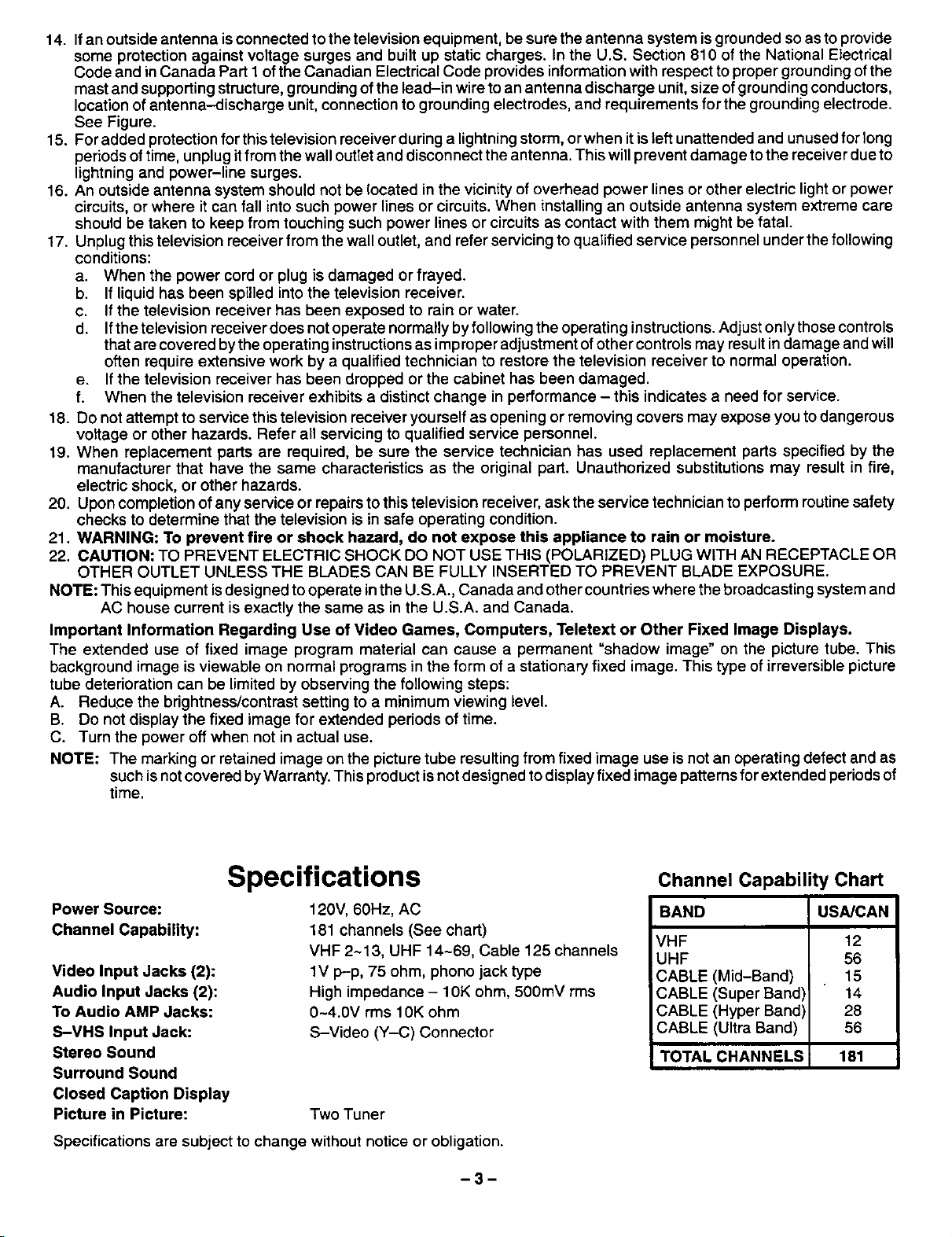
Specifications
Power Source:
Channel Capability:
Video Input Jacks (2):
Audio Input Jacks (2):
To Audio AMP Jacks:
S-VHS Input Jack:
Stereo Sound
Surround Sound
Closed Caption Display
Picture in Picture:
Specifications are subject to change without notice or obligation.
120V, 60Hz, AC
181 channels (See chart)
VHF 2~13, UHF 14-69, Cable 125 channels
1V p-p, 75 ohm, phono jack type
High impedance - 10K ohm, 500mV rms
0-4.0V rms 10K ohm
S-Video (Y-C) Connector
Two Tuner
-3-
Channel Capability Chart
BAND USA/CAN
VHF 12
UHF 56
CABLE (Mid-Band) 15
CABLE (Super Band) 14
CABLE (Hyper Band) 28
CABLE (Ultra Band) 56
TOTAL CHANNELS 181
Introduction
Congratulations on Your New Purchase
Your new video component features an allsolid state chassis which is designed to give you many years of enjoyment. It
was thoroughly tested and adjusted at the factory for best performance.
In order for you to take full advantage of your newvideo component, please read and follow the installation and operating
instructions supplied with this product.
Customer's Record
The model and serial number of this product may be found on its back cover. You should note the model and serial number
in the space provided and retain this book as a permanent record of your purchase to aid in identification in the event of
theft or loss.
Model Number: Serial Number:
Table of Contents
Safety Instructions ............................. 2
Specifications ................................. 3
Introduction ................................... 4
Installation .................................... 5
Receiver Location .............................. 5
Optional External Equipment Connections ......... 5
AC Power Supply Cord ......................... 5
Remote Control Battery Installation ............... 5
Antenna/Cable Connections ..................... 6
Picture in Picture External Video and Ant
Connection .................................... 7
Optional Equipment Connection and Operation .. 8
To Audio AMP Connection (stereo) .............. 8
Video/Audio Connection ........................ 8
S-Videc Connection ............................ g
Location of Controls (Receiver) ................ 10
Location of Controls (Remote) ................. 11
Remote Quick Reference Key Chart ............ 12
Control Operation ............................. 14
Power Button ................................. 14
Volume (Vol) Buttons .......................... 14
Mute Button .................................. 14
Channel Change Features ..................... 14
Channel (Ch) Buttons ....................... 14
Keyboard "0 through 9" Buttons ............... 14
VCR Function Buttons ......................... 14
TV/Video Button .............................. 15
Recall Button ................................. 15
R-Tune (Rapid Tune) Button ................... 15
Multi Button .................................. 15
PIP (Picture in Picture) Button .................. 16
Swap Button ................................. 16
Size Button .................................. 16
Freeze Button ................................ 17
PIP Channel Buttons .......................... 17
Move Button ................................. 17
Search Button ................................ 17
Main Menu (Icons) ............................ 18
Picture Adjustments ........................... 19
Picture Norm ............................... 19
Color ...................................... 19
Tint ....................................... 19
Brightness ................................. 19
Picture .................................... 19
Sharpness ................................. 19
Audio Adjustments ............................ 20
Audio Norm ................................ 20
Bass, Treble & Balance Adjustments .......... 20
Audio Mode (Stereo/SAP/Mono) ............. 21
AI Sound .................................. 22
Surround Sound ............................ 23
TV Speakers ............................... 24
Game Guard ................................. 25
Lock Game Guard .......................... 25
Unlock Game Guard ........................ 26
Channel Caption (Station Identifier) .............. 27
Timer Features ............................... 28
Sleep "l]mer ................................ 28
Program Timer ............................. 29
Set-Up Features .............................. 30
Set Time (Clock) ............................ 30
Antenna Tuning Mode ....................... 31
Auto Program .............................. 32
Manual Program ............................ 33
CC (Closed Caption) On Mute ................ 34
CC (Closed Caption) Mode ................... 35
English/French Menu .......................... 36
Programming The Universal Remote Control .... 37
VCR Infrared Codes Index ..................... 38
Cable Converter Box & CD Player Codes ........ 39
Cassette Players and AV Receivers Codes ...... 40
laser Disc/DSS/TV/&DVD Codes ............... 41
Care & Cleaning ............................... 42
Power Loss ................................... 42
Troubleshooting Chart ........................ 43
-4-
Installation
Receiver Location
This unit is intended to be used with an optional stand or entertainment center. Consult your dealer for available options.
Locate for comfortable viewing. Avoid placing where sunlight or other bright light (including reflections) will fall on the
screen.
Use of some types of fluorescent lighting can reduce remote control transmitter range.
Adequate ventilation is essential to prevent internal component failure. Keep away from areas of excessive heat or
moisture.
To insure optimum color purity do not position magnetic equipment (motors, fans, other speakers, etc.) nearby.
Optional External Equipment Connections
The Video/Audio connections between components can be made with shielded video and audio cables. Forbest perfor-
mance, video cables should utilize 75 ohm coaxial shielded wire. Cables are available from your dealer or electronic
supply house.
Before you purchase any cables, be sure you know what type of output and input connectors you rvarious components
require. Also determine the length of cable you'll need.
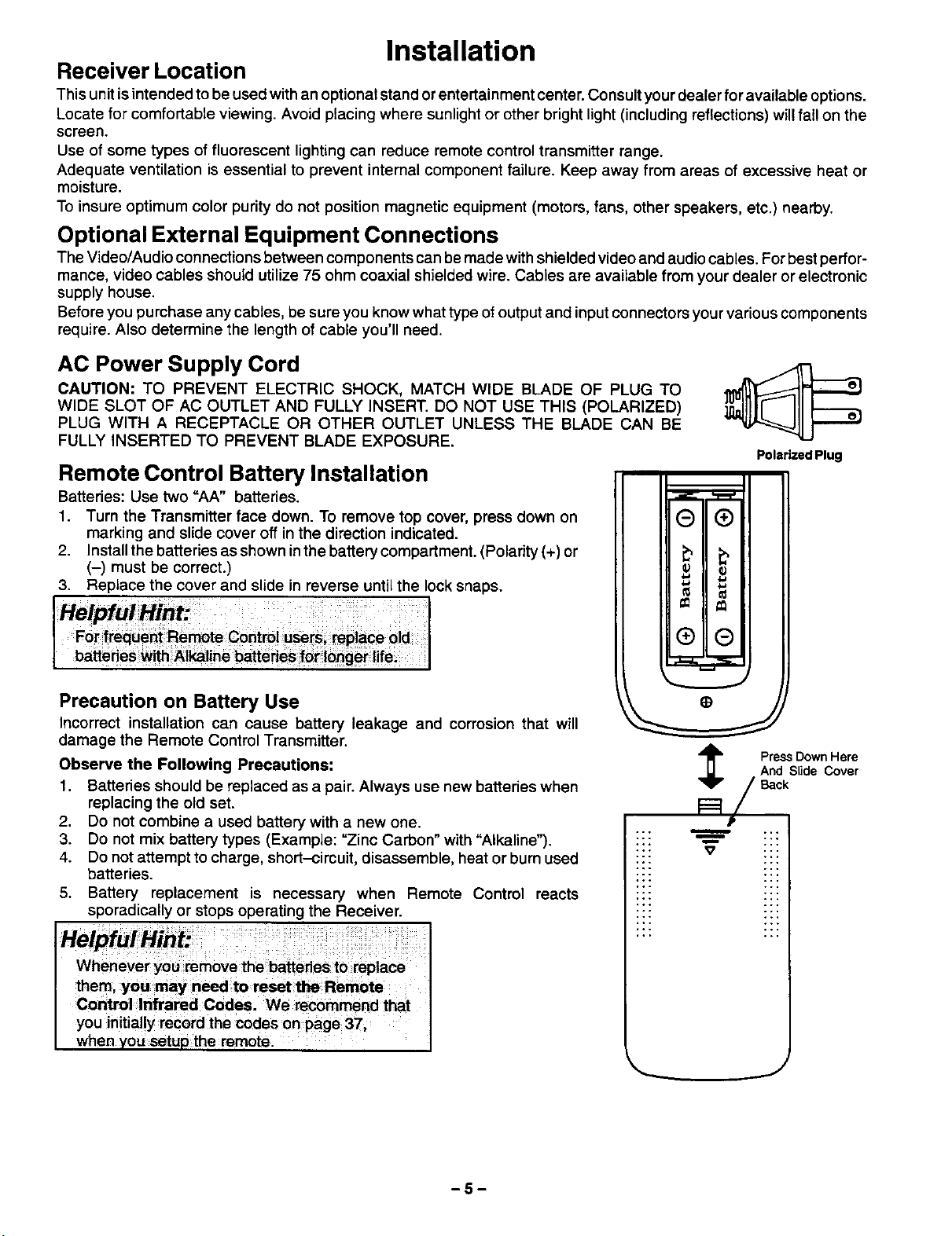
AC Power Supply Cord
CAUTION: TO PREVENT ELECTRIC SHOCK, MATCH WIDE BLADE OF PLUG TO
WIDE SLOT OF AC OUTLET AND FULLY INSERT. DO NOT USE THIS (POLARIZED)
PLUG WITH A RECEPTACLE OR OTHER OUTLET UNLESS THE BLADE CAN BE
FULLY INSERTED TO PREVENT BLADE EXPOSURE.
PolarizedPlug
Remote Control Battery Installation
Batteries: Use two "AA" batteries.
1. Turn the Transmitter face down. To remove top cover, press down on
marking and slide cover off in the direction indicated.
2. Install the batteries as shown in the battery compartment. (Polarity (+) or
(-) must be correct.)
3. Replace the cover and slide in reverse until the lock snaps.
Precaution on Battery Use
Incorrect installation can cause battery leakage and corrosion that will
damage the Remote Control Transmitter.
Observe the Following Precautions:
1. Batteries should be replaced as a pair. Always use new batteries when
replacing the old set.
2. Do notcombine a used battery with a new one.
3. Do notmix battery types (Example: "Zinc Carbon" with "Alkaline").
4. Do not attempt to charge, short-circuit, disassemble, heat or burn used
batteries.
5. Battery replacement is necessary when Remote Control reacts
sporadically or stops operating the Receiver.
them, you may need to reset the Remote
Control Infrared Codes. We recommend that
you initially record the codes on page 37,
w_qenyou setup the remote.
,_ PredSsS_enc_evre
Back
m
::: --"
J
-5-
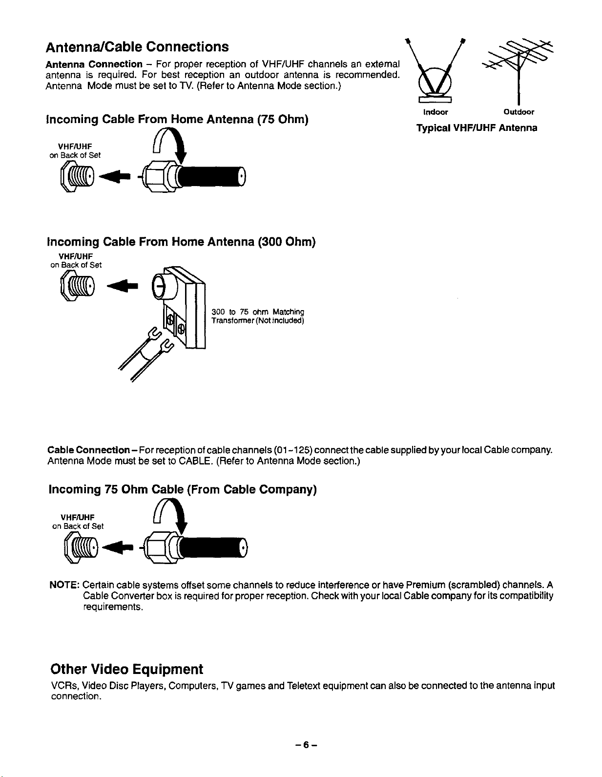
Antenna/Cable Connections
Antenna Connection - For proper reception of VHF/UHF channels an external
antenna is required. For best reception an outdoor antenna is recommended.
Antenna Mode must be set to "IV. (Refer to Antenna Mode section.)
Incoming Cable From Home Antenna (75 Ohm)
VHF/UHF
onBackofSet
Incoming Cable From Home Antenna (300 Ohm)
VHF/UHF
onBackofSet
300 to 75 ohm Matching
Transformer(Not Included)
Indoor Outdoor
Typical VHF/UHF Antenna
Cable Connection- For reception ofcable channels (01 - 125) connect the cable supplied by your localCable company.
Antenna Mode must be set to CABLE. (Refer to Antenna Mode section.)
Incoming 75 Ohm Cable (From Cable Company)
VHF/UHF
onBackofSet
NOTE: Certain cable systems offset some channels to reduce interference or have Premium (scrambled) channels. A
Cable Converter box isrequiredfor proper reception. Check with your localCable company for itscompatibility
requirements.
Other Video Equipment
VCRs, Video Disc Players, Computers, TV games and Teletext equipment can also be connected to the antenna input
connection.
-6-
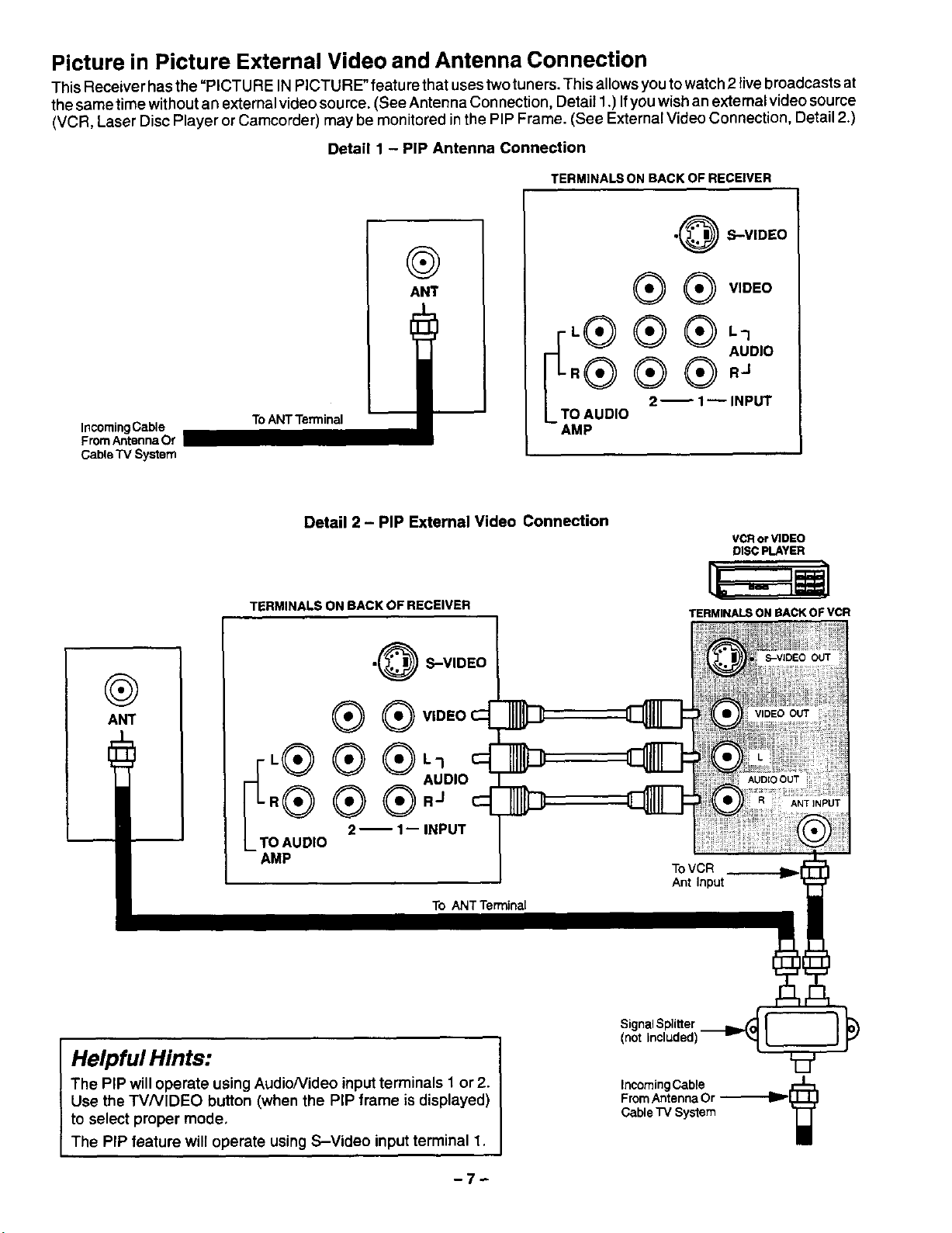
Picture in Picture External Video and Antenna Connection
This Receiver has the "PICTU RE IN PICTURE" featu rethat uses twotuners. This allowsyou to watch 2 live broadcasts at
thesame time without an external videosource. (See Antenna Connection, Detail 1.) Ifyou wish an external video source
(VCR, Laser Disc Player or Camcorder) may be monitored in the PIP Frame. (See External Video Connection, Detail 2.)
Detail 1 - PIP Antenna Connection
TERMINALS ON BACK OF RECEIVER
•@ S-VIDEO
®
Incoming Cable
From Antenna Or
Cable "IV System
To ANT Terminal
ANT
.® ® ® _UD,O
iT'® ® ®'_
O AUDIO
AMP
@ VIDEO
2 _ 1_ INPUT
@
ANT
Detail 2 - PIP External Video Connection
TERMINALS ON BACK OF RECEIVER
•@ S-VIDEO
®®
•® ® ®L1
fT.® ® ®'OD'O
O AUDIO
AMP
2-- 1-- INPUT
To ANT Terminal
VCR or VIDEO
DISC PLAYER
TERMINALS ON SACK OF VCR
S-VIDEO OUT
VIDEO OUT
AUDIO OUT
ANT INPUT
ToVCR
Ant Input
Helpful Hints:
The PIP will operate using Audio/Video input terminals I or 2.
Use the TV/VIDEO button (when the PIP frame is displayed)
to select proper mode,
The PIP feature will operate using S-Video input terminal 1,
-7-
SignalSplitter
(not Included)
incoming Cable J_Z:L
From Antenna Or --_ [L.LL_
Cable "IV System "1--1"
/
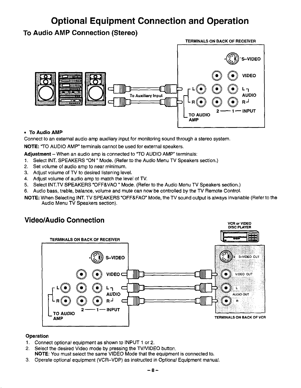
Optional Equipment Connection and Operation
To Audio AMP Connection (Stereo)
ToAuxiliaryInput AUDIO
TERMINALS ON BACK OF RECEIVER
.@'S-VIDEO
@ VIDEO
TO AUDIO
AMP
• To Audio AMP
Connect to an external audio amp auxiliary input for monitoring sound through a stereo system.
NOTE: "TO AUDIO AMP" terminals cannot be used for external speakers.
Adjustment - When an audio amp is connected to "TO AUDIO AMP" terminals:
1. Select INT. SPEAKERS "ON" Mode. (Refer to the Audio Menu TV Speakers section.)
2. Set volume of audio amp to near minimum.
3. Adjust volume of TV to desired listeninglevel.
4. Adjust volume of audio amp to match the level of "IV.
5. Select INT.TV SPEAKERS "OFF&VAO" Mode. (Refer to the Audio Menu TV Speakers section.)
6. Audio bass, treble, balance, volume and mute can now be controlled by the TV Remote Control.
NOTE: When Selecting INT. -IV SPEAKERS "OFF&FAO" Mode, the TV sound output is always invariable (Refer to the
Audio Menu "iV Speakers section).
Video/Audio Connection
TERMINALS ON BACK OF RECEIVER
2 _ I m INPUT
VCR or VIDEO
DISC PLAYER
•@ S-VIDEO
®®
AUDIO
.® ® ®."
0 AUDIO
AMP
Operation
1. Connect optional equipment as shown to INPUT 1 or 2.
2. Select the desired Video mode by pressing the TV/VIDEO button.
NOTE: You must select the same VIDEO Mode that the equipment is connected to.
3. Operate optional equipment (VCR-VDP) as instructed in Optional Equipment manual.
2 _ 1-- INPUT
TERMINALS ON BACK OF VCR
-8-
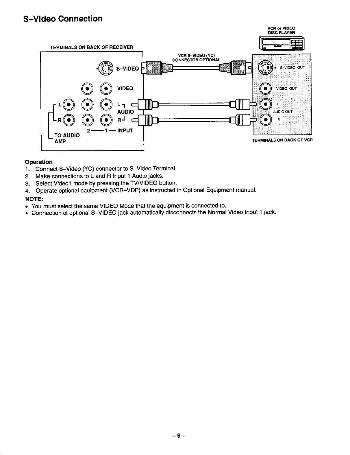
S-Video Connection
VCR or VIDEO
TERMINALS ON BACK OF RECEIVER
VCR S-VIDEO (YC)
CONNECTOROPTIONAL
•@ S-VIDEO
@ VIDEO
.® ® ®_,
IT'® ® ® _,;D,O
O AUDIO
AMP
Operation
1. Connect S-Video (YC) connector to S-Videc Terminal.
2. Make connections to L and R Input 1 Audio jacks.
3. Select Video1 mode by pressing the TVNIDEO button.
4. Operate optional equipment (VCR-VDP) as instructed in Optional Equipment manual.
NOTE:
• You must select the same VIDEO Mode that the equipment isconnected to.
• Connection ofoptional S-VIDEO jack automatically disconnects the Normal Video Input 1 jack.
2-- 1-- INPUT
TERMINALS ON BACK OF VCR
DISC PLAYER
-9-
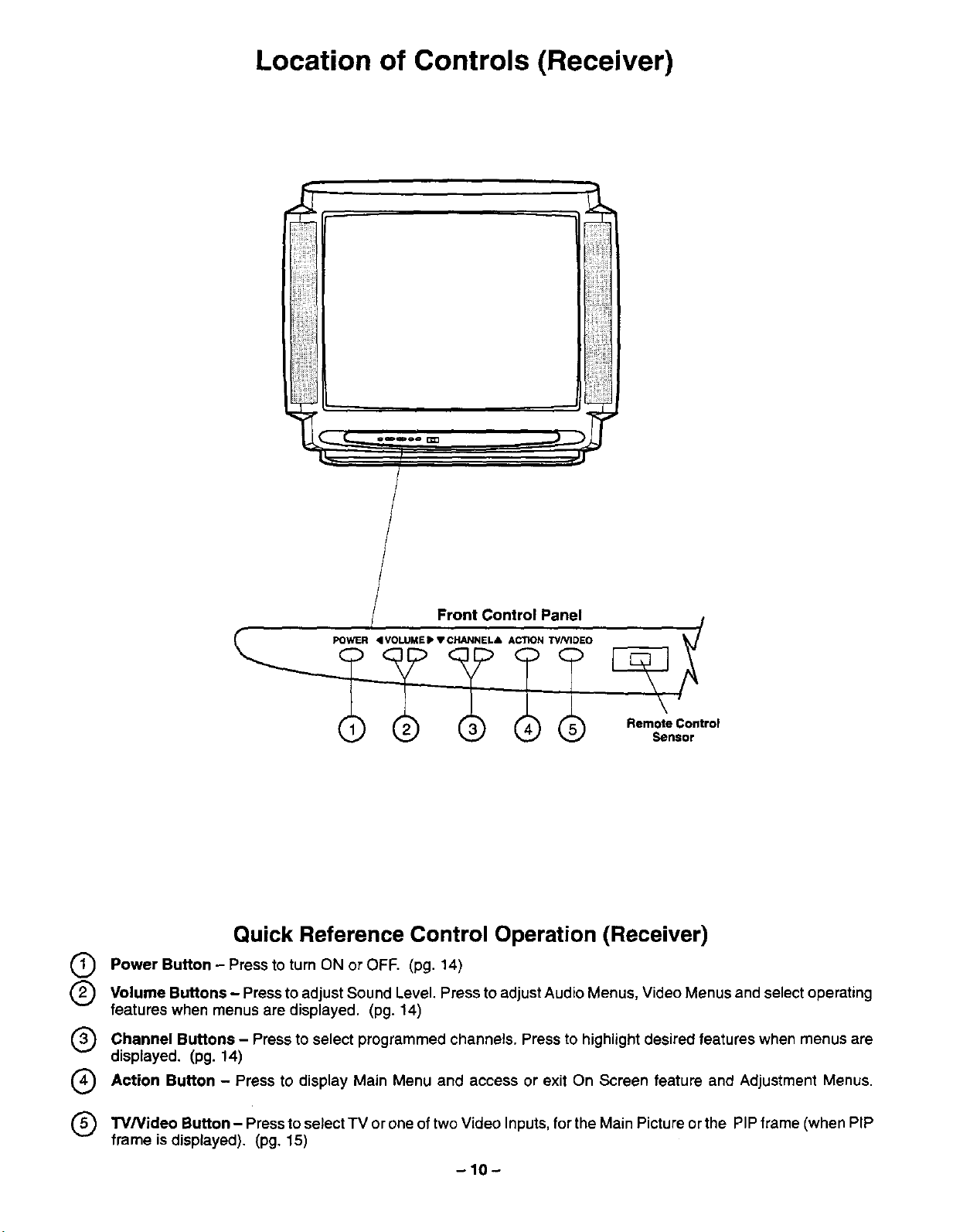
Location of Controls (Receiver)
Front Control Panel
Remote Control
Sensor
Quick Reference Control Operation (Receiver)
Q Power Button - Press to turn ON or OFF. (pg. 14)
Q Volume Buttons - Press to adjust Sound Level. Press to adjust Audio Menus, Video Menus and select operating
features when menus are displayed, (pg. 14)
Channel Buttons - Press to select programmed channels. Press to highlight desired features when menus are
displayed. (pg. 14)
Q Action Button - Press to display Main Menu and access or exit On Screen feature and Adjustment Menus.
W/Video Button Press to select TV oftwo Video for the Main Picture the PIP frame PIP
frame is displayed). (pg, 15)
or one
-10-
Inputs,
or
(when
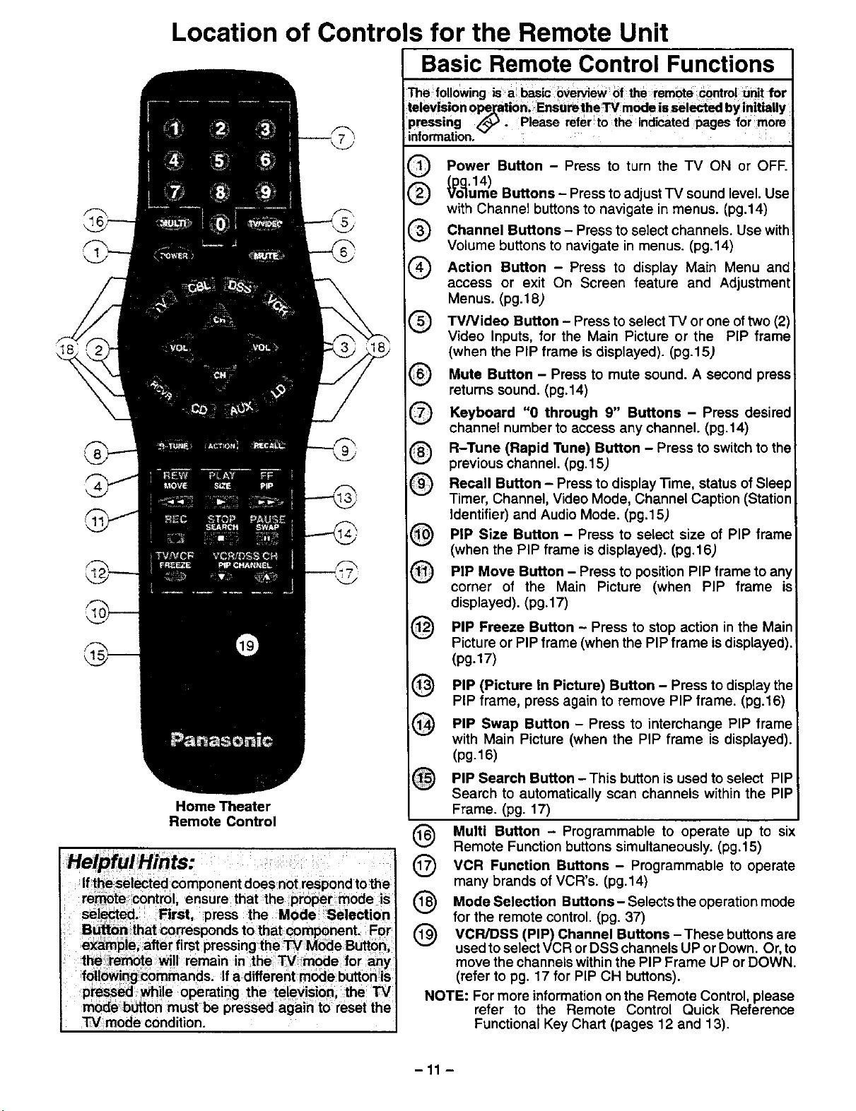
Location of Controls for the Remote Unit
Basic Remote Control Functions
iThe followingis a basic 0vervieWof the remote controtunitfor
televisionOPe_ati0n;Enstl_the W mode is selectedbyinitially
pressing _. Please refer to the indicatedpages for morn
information.
Power Button - Press to turn the TV ON or OFF.
_o_.14)
ume Buttons- Press to adjust"IV sound level. Use
with Channel buttons to navigate inmenus. (pg.14)
Channel Buttons - Press to select channels. Use with
®
Volume buttons to navigate in menus. (pg.14)
Action Button - Press to display Main Menu and
®
access or exit On Screen feature and Adjustment
Menus. (pg.18)
TV/Video Button - Press to select "IV or one of two (2)
®
Video Inputs, for the Main Picture or the PIP frame
(when the PIP frame is displayed). (pg.15)
Mute Button - Press to mute sound. A second press
®
returns sound. (pg.14)
Keyboard "0 through 9" Buttons - Press desired
®
channel number to access any channel. (pg.14)
R-Tune (Rapid Tune) Button - Press to switch to th_
®
previous channel. (pg.15)
Recall Button - Press to display -time, status of Slee
®
Timer, Channel, Video Mode, Channel Caption (Station
Identifier) and Audio Mode. (pg.15)
PIP Size Button - Press to select size of PIP frame
®
(when the PIP frame is displayed). (pg.t 6)
PIP Move Button - Press to position PIP frame to any
®
corner of the Main Picture (when PIP frame is
displayed). (pg.17)
PIP Freeze Button Press to action in the Main
Picture or PIP frame (when the PIP frame isdisplayed).
(pg.17)
stop
Home Theater
Remote Control
Helpful Hints:
Iftheselected component does not respond to the
remote control, ensure that the proper mode is
selected. First, press the Mode Selection
Button that corresponds to that component. For
example, after first pressing the TV Mode Button
the =remote will remain in the TV mode for any
following commands. If a different mode buttonis
pressed while operating the television, the "rv
mode button must be pressed again to reset the
TV mode condition.
PIP (Picture In Picture) Button - Press to display the
@
PIP frame, press again to remove PIP frame. (pg.16)
PIP Swap Button - Press to interchange PIP frame
@
with Main Picture (when the PIP frame is displayed).
(pg.16)
PIP Search Button This button isused to select PIP
Search to automatically scan channels within the PIP
Frame. (pg. 17)
(_) Multi Button - Programmable to operate up to s=x
Remote Function buttons simultaneously. (pg.15)
VCR Function Buttons to
many brands of VCR's. (pg.14)
Mode Selection B_lons-Selectstheoperationmode
for the remote control. (pg. 37)
VCR/DSS Channel Buttons These buttons
used toselect VCR orDSS channels UP or Down. Or, to
move the channels withinthe PIP Frame UP or DOWN.
(refer to pg. 17 for PiP CH buttons).
NOTE: For more information on the Remote Control, please
-11 -
refer to the Remote Control Quick Reference
Functional Key Chart (pages 12 and 13).
(PIP)
Programmable operate
are
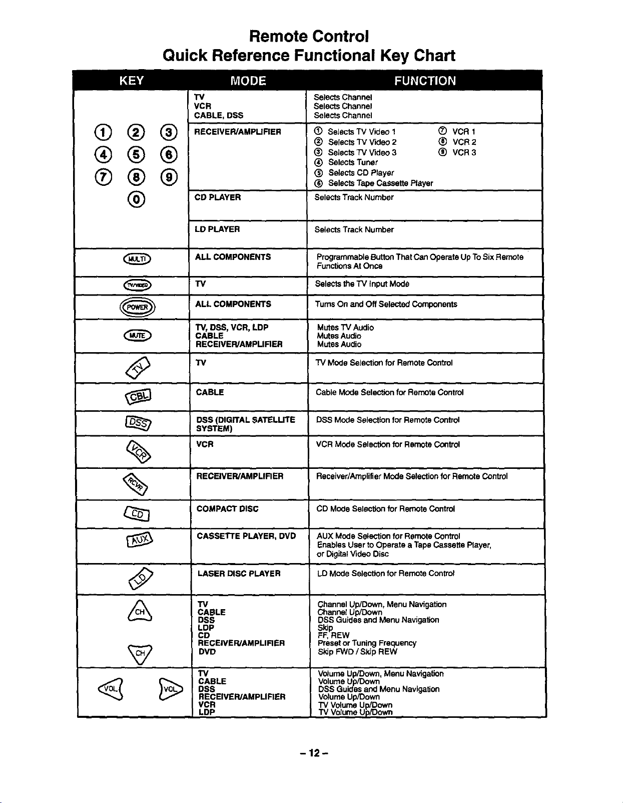
Remote Control
Quick Reference Functional Key Chart
TV
VCR
CABLE, DSS
(_ (_) (_ RECEIVER/AMPURER (_ Selects TV Video I (Z) VCR1
(_) (_ _) (_ Selects TV Video 3 (_ VCR3
O (_ (_) _) Seleots Tape Cassette Player
CO PLAYER Selects Track Number
LD PLAYER Selects Track Number
ALL COMPONENTS Programmable Button That Can Operate Up To Six Remote
(_ TV Selects the "iV Input Mode
ALL COMPONENTS Turns On and Off Selected Components
"rvt DSS, VCR, LDP Mutes "IV Audio
CABLE Mutes Audio
RECEIVER/AMPLIRER Mutes Audio
<_ "IV "iV Mode Selection for Remote Control
SeleCts Channel
Selects Channel
Selects Channel
_) Selects TV Video 2 (_) VCR 2
(_) Selects Tuner
(_) Selects CD Player
Functions At Once
O
CABLE Cable Mode Seleotion for Remote Control
DSS (DIGITAL SATELLITE DSS Mode Selection for Remote Control
SYSTEM)
VCR VCR Mode Selection for Remote Control
RECEIVER/AMPMRER Receiver/Amplifier Mode Selection for Remote Control
COMPACT DISC CD Mode Selection for Remote Control
CASSETTE PLAYER, DVD
LASER DISC PLAYER
TV
CABLE
DSS
LDP
CD
RECEIVER/AMPLIRER
DVD
TV
CABLE
DSS
RECEIVER/AMPLIRER
VCR
LDP
AUX Mode Selection for Remote Control
Enables User to Operate a Tape Cassette Player,
or Digital Video Disc
LD Mode SeleolJon for Remote Contr_
Channel Up/Down, Menu Navigation
Channel Up/Down
DSS Guides and Menu NavigalJon
S_dp
FF, REW
Preset or Tuning Frequency
Skip FWD/SkJp REW
Volume Up/Down, Menu Navigation
Volume Up/Down
DSS Guides and Menu NavigalJon
Volume Up/Down
TV Volume Up/l_own
TV Volume Up/Down
-12-
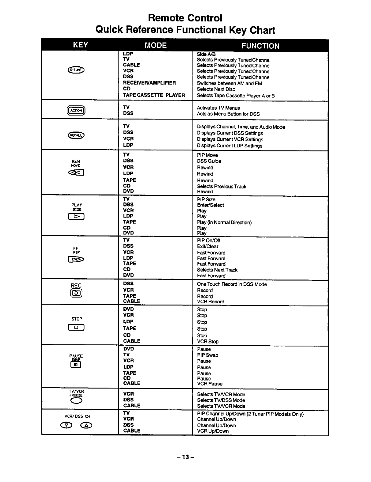
Remote Control
Quick Reference Functional Key Chart
LDP
TV
CABLE
VCR
DSS
RECEIVEPJAMPLIRER
CD
TAPE CASSEn'E PLAYER
TV
DSS
TV
DSS
VCR
LDP
TV
REW
MOVE
DSS
VCR
LDP
TAPE
CD
DVD
TV
PLAY
SI2E
DSS
VCR
LOP
TAPE
CD
DVD
"IV
FF
PIP
DSS
VCR
LDP
TAPE
CD
DVD
REC
DSS
VCR
TAPE
CABLE
DVD
STOP
VCR
LDP
TAPE
CD
CABLE
DVD
PAUSE
EE}
TV
VCR
LDP
TAPE
CD
CABLE
TV/VCR
F_E2E Selects TVNCR Mode
(_ Selects "r'v.,'DSSMode
VCR/DSSCH
VCR
DSS
CABLE
TV
VCR
DSS
CABLE
Side A/B
Selects Previously Tuned Channel
Selects Previously Tuned Channel
Selects Previously Tuned Channel
Selects Previously Tuned Channel
Switches between AM and FM
Selects Next Disc
Selects Tape Cassette Player A or B
ActivatesTVMenus
Actsas MenuButtonfor DSS
Displays Channel, Time, and Audio Mode
Displays Current DSS Settings
Displays Current VCR Settings
Displays Current LDP Settings
PIP Move
DSS Guide
Rewind
Rewind
Rewind
Selects Previous Track
Rewind
PIP Size
Enter/Select
Ray
Pray
Play (in Normal Direction)
Play
Play
PiP On/Off
Exit/Clear
Fast Forward
Fast Forward
Fast Forward
Selects Next Track
Fast Forward
One Touch Record in DSS Mode
Record
Record
VCR Record
Stop
Stop
Stop
Stop
Stop
VCR Stop
Pause
PIP Swap
Pause
Pause
Pause
Pause
VCR Pause
Selects TV/VCR Mode
PIP ChannelUp/Down(2Tuner PIPModelsOnly)
ChannelUp/Down
ChannelUp/Down
VCR Up/Down
-13-
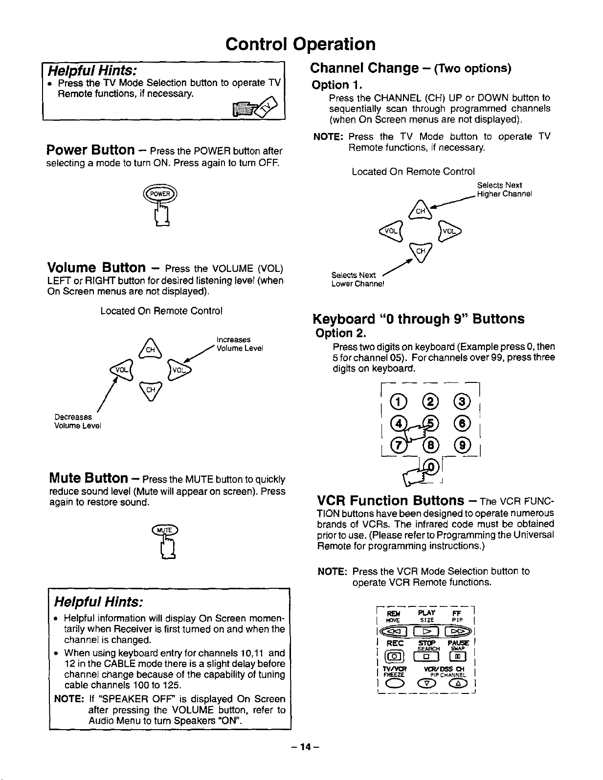
Control Operation
I " Press the TV Mode Selection button to
Helpful Hints: _ I
I Remote functions, if necessary.
Power Button - Press the POWER button after
selecting a mode to turn ON. Press again to turn OFF.
Channel Change - (Twooptions)
Option 1.
Press the CHANNEL (CH) UP or DOWN button to
sequentially scan through programmed channels
(when On Screen menus are not displayed).
NOTE: Press the TV Mode button to operate TV
Remote functions, if necessary.
Located On Remote Control
Selects Next
)/Higher Channel
Volume Button - Press the VOLUME (VOL)
LEFT or RIGHT button for desired listening level (when
On Screen menus are not displayed).
Located On Remote Control
Volume Level
(_ _)/Increases
/
Decreases
Volume Level
Mute Button - Press the MUTE button to quickly
reduce sound level (Mute will appear on screen). Press
again to restore sound.
Selects Next /_
Lower Channel
Keyboard "0 through 9" Buttons
Option 2.
Press two digits on keyboard (Example press 0, then
5 forchanne105). For channels over 99, pressthree
digits on keyboard.
I @l
L
VCR Function Buttons - TheVCRFUNC-
TIONbuttons have been designed to operate numerous
brands of VCRs. The infrared code must be obtained
prior to use. (Please refer to Programming the U niversal
Remote for programming instructions.)
Helpful Hints:
• Helpful information will display On Screen momen-
tarily when Receiver is first turned on and when the
channel is changed.
• When using keyboard entry for channels 10,11 and
12 in the CABLE mode there is a slight delay before
channel change because of the capability of tuning
cable channels 100 to 125.
NOTE: If "SPEAKER OFF" is displayed On Screen
after pressing the VOLUME button, refer to
Audio Menu to turn Speakers "ON".
NOTE: Press the VCR Mode Selection button to
operate VCR Remote functions.
[ REN Pt_Y FF
I HOVE SIZE PIP
J REC $TOP PAIJ_E
I
I p'RIEEZE pIp CHANNEL
IC_ Q O
I
-14-
 Loading...