

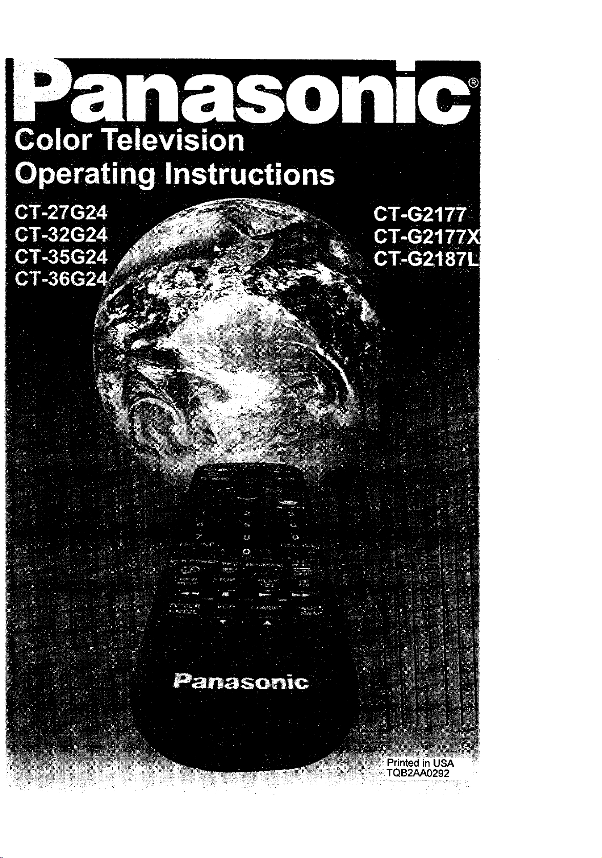
Panasonic CT-32G24, CT-27G24 Owner’s Manual
,, qD
TABL E OF CONTENTS '
Table of Contents
Congratulations ............................................................ 3
Customer Record ....................................................... 3
Care and Cleaning ..................................................... 3
Specifications ........ :.................................................... 3
Installation .................................................................... 4
Television Location .................................................... 4
Optional Cable Connections ...................................... 4
AC Power Supply Cord .............................................. 4
Cable / Antenna ......................................................... 4
Cable Connection ...................................................... 4
Antenna Connection .................................................. 5
Optional Equipment Connections ............................... 5
To Audio Amplifier ...................................................... 6
Audio Adjustmerlts ..................................................... 6
Main Menu ..................................................................... 6
ACTION Button ................... :...................................... 6
CH / VOL Buttons ....................................................... 6
Picture in Picture (PIP) Operation ............................... 7
PIP Operation with a VCR and Cable Box ................. 7
PIP Operation with a VCR - No Cable Box ................ 8
Main Menu Feature Chart ............................................ 9
Special Features ......................................................... 11
Languages ............................................................... 11
Timer ........................................................................ 11
Sleep Timer .............................................................. 11
Program Timer ......................................................... 11
CH CAP (Channel Caption) ..................................... 12
LOCK ....................................................................... 13
Game Guard Lock and Unlock ................................. 13
Troubleshooting Chart ............................................... 14
Safety Instructions
B
WARNING
head within a thangle is triangle is intended to tell the
intended to tell the user that user that important Operating
The lightning flash with arrow The exclamation point within a
parts inside the product are a andservicinginstructionsare in
riskof electricshockto parsons, the papers withthe applk_rtce.
WARNING: To prevent fire or shock hazard, do not expose this appliance to
rain or moisture_
Read these instructions oompletely before operating TV.
Contents ere subject to change without notice or obligation.
Copyright1999 by MaleushileElectricCorporati_'lof America. All rights reserved.
Unauthorizedcopyingand distdburtonis a violationof law.
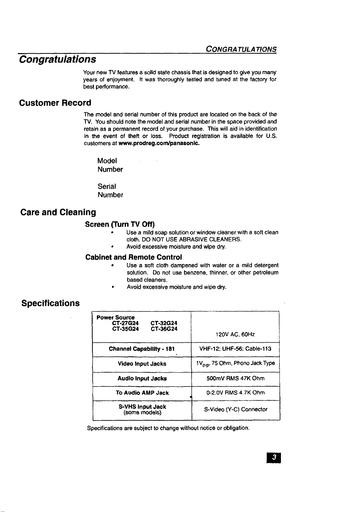
Congratulations
YournewTV features a solidstate chassisthatis designedto giveyou many
years of enjoyment. It was thoroughlytested and tuned at the factory for
best performance.
Customer Record
Care and Cleaning
CONGRA TULA TIONS
The model and serial number of this productare located on the back of the
TV. You shouldnote the modeland serial numberinthe spaceprovidedand
retain as a permanent record ofyour pumhase. This willaid in identification
in the event of theft or loss. Product registration is available for U.S,
customersat www.prodreg.condpanasonic.
Model
Number
Serial
Number
Specifications
Screen (Turn TV Off)
• Usea mildsoap solutionor windowcleaner witha soft clean
cloth.DO NOT USE ABRASIVE CLEANERS.
• Avoid excessive moistureand wipe dry.
Cabinet and Remote Control
• Use a soft clothdampened with water or a mild detergent
solution. Do not use benzene, thinner, or other petroleum
based cleaners.
• Avoidexcessive moistureand wipe dry.
Power Source
CT-27G24 CT-32G24
CT-35G24 CT-36G24 I
Channel Capability- 181 VHF-12; UHF-56; Cable-113
Video Input Jacks tVp.p,75 Ohm, PhonoJackType
Audio Input Jacks 500mV RMS 47K Ohm
,., H
To Audio AMP Jack 0-2.0V RMS 4.7K Ohm
.....,,,, ,,
S-VHS Input Jack S-Video (Y-C) Connector
(somemode_s)
120V AC, 60Hz
Specificationsare subjectto change withoutnotice or obligation.
El
INSTALLATION
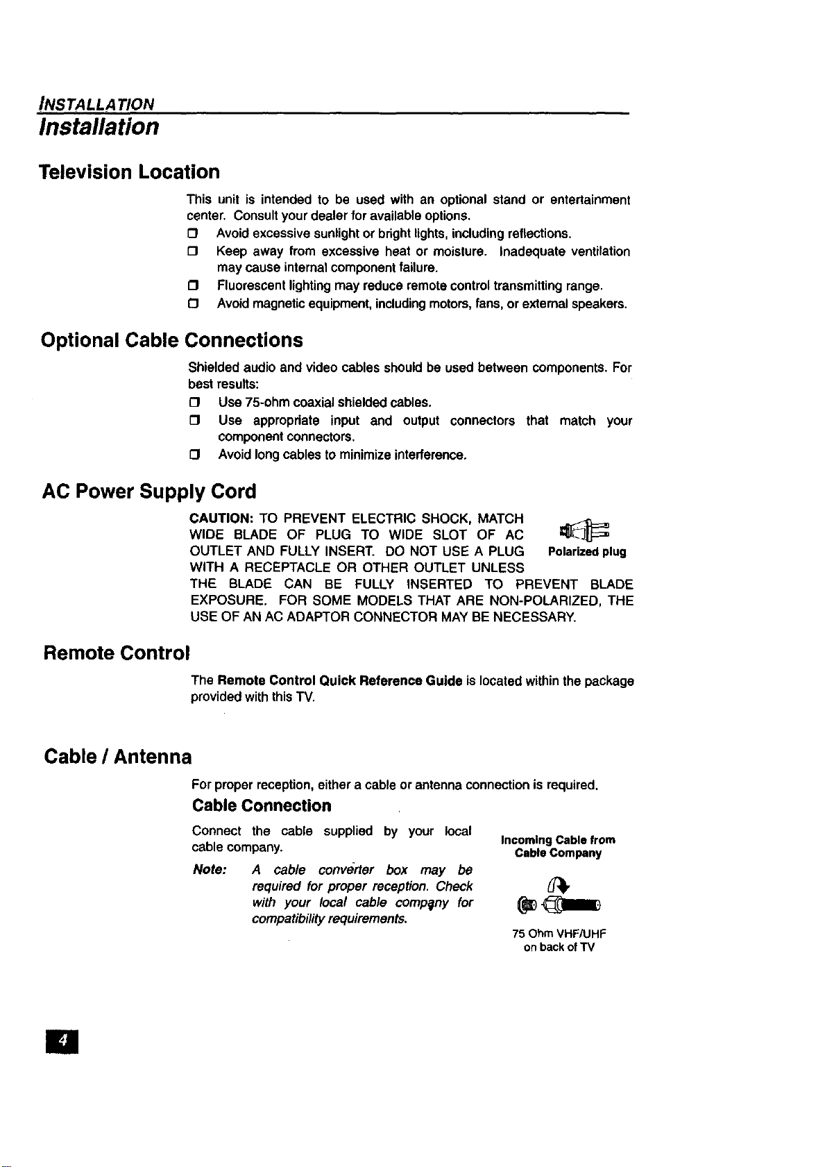
Installation
Television Location
This unit is intended to be used with an optional stand or entertainment
center. Consultyour dealer for available options.
[_ Avoid excessivesunlightor brightlights, includingreflections.
[] Keep away from excessive heat or moisture. Inadequate ventilation
may cause internal componentfailure.
[] Fluorescentlightingmay reduce remotecontroltransmittingrange.
[3 Avoid magneticequipment,including motors,fans, orexternalspeakers.
Optional Cable Connections
Shielded audio and video cables should be used between components. For
best results:
O Use 75-ohm coaxialshielded cables.
[] Use appropriate input and output connectors that match your
componentconnectors.
[] Avoidlongcables tominimize interference.
AC Power Supply Cord
CAUTION: TO PREVENT ELECTRIC SHOCK, MATCH
WIDE BLADE OF PLUG TO WIDE SLOT OF AC _JL E_
OUTLET AND FULLY INSERT. DO NOT USE A PLUG Polarizedplug
WITH A RECEPTACLE OR OTHER OUTLET UNLESS
THE BLADE CAN BE FULLY INSERTED TO PREVENT BLADE
EXPOSURE. FOR SOME MODELS THAT ARE NON-POLARIZED, THE
USE OF AN AC ADAPTOR CONNECTOR MAY BE NECESSARY.
Remote Control
Cable / Antenna
I
The Remote Control Quick Reference Guide is locatedwithinthe package
providedwiththis TV.
Forproper reception,either a cable orantenna connectionisrequired.
Cable Connection
Connect the cable supplied by your local
cable company.
Note:
A cable converter box may be
required for proper reception. Check {_,
with your local cable company for _1_
compatibilityrequirements.
Incoming Cable from
Cable Company
75 Ohm VHF/UHF
onback ofTV
Antenna Connection
• For proper reception of VHF/UHF IncomlngCablofrom
channels, an external antenna is HomeAntenna
required. For best reception an I_q t"_
outdoorantenna isrecommended.
• Antenna Mode must be set toTV.
\ I .....
_ Cable Preset
Cable Mode is preset at the factory. Antenna
users must change to Antenna Mode in the
Setup Menu.
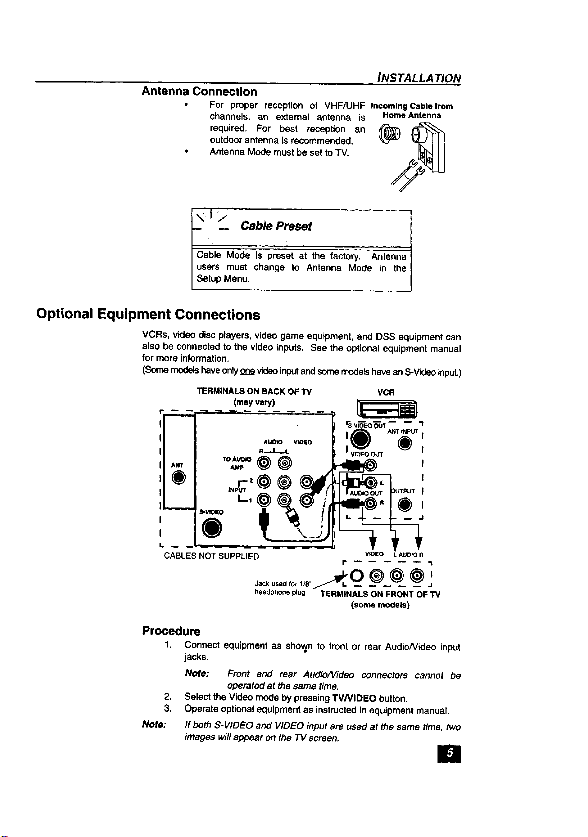
Optional Equipment Connections
VCRs, video discplayers, video game equipment, and DSS equipment can
also be connected to the video inputs. See the optional equipment manual
for more information.
(Some modelshaveonly onevideoinputandsome modelshavean S-V'_eoinput.)
INS TALLA TION
TERMINALS ON BACK OF TV VCR
(may vary)
®
CABLES NOT SUPPLIED WDEO LAUD_OR
Jack used for l/8- _L O _ _ _)/
headphoneplug TERMINALS ON FRONT OF TV
Procedure
1. Connect equipment as shoranto front or rear Audio/Video input
jacks.
Note: Front and rear Audio/Video connectors cannot be
operated at the same time.
2.
Select the Videomode by pressingTVNIDEO button.
3.
Operate optionalequipmentas instructedinequipment manual.
Note:
If bothS-VIDEO and VIDEO input are usedat the same time, two
images willappear on the TV screen.
I" "1
(some models)
E1
 Loading...