

Panasonic CT-32G21 Operating Instructions Manual
i
M r_..- r
Color Television
Operating Instructions
®
0_-32G21
Read these instructions completely before operating [hLs sul.
Contents subject to change without notice or obligation.
Copyright 1995 by Matsushita Electric Corporation of Ame dca.
Allrights reserved. Unauthorized copying and distribution isa violation of law.
t'rlnl[ed in USA,
TQB2AA0057
Safety Instructions
WARNING
WARNING: To reduce the risk ofelectric shock do not remove cover or back. No
user-serviceable parts inside, Refer servicing to qualified service personnel.
The lightningflash withar- Theexclamationpointwithin
,__ row-head within a triangle ,_ a triangle is intended to tell
is intended to tell the user ,__ the userthatimportantoper-
that partsinsidetheproduct ating and servicing instruc-
area riskof electricshockt(_ tions are in the papers with
persons, the appliance.
Note To CATV System Installer: This reminder is provided to call the CATV system installer's attention to Article
820-40 of the NEC that provides guidelines for proper grounding and, in particular, specifies that the cable ground shall be
connected to the grounding system of the building, as close to the point of cable entry as practical.
Safety Instructions For Television Receivers
1. Read and apply the operating instructionsprovided with your television receiver.
2. Read all of the instructions given here and retain them for later use.
3. Unplug this television receiver from the wall outlet before cleaning. Do not use liquid or aerosol cleaners. Use a damp
cloth for cleaning.
4. Do not use attachments not recommended by the television receiver manufacturer as they may cause hazards.
5. Do not use this television receiver near water. For example: Avoid placing it near a bathtub, washbowl, kitchen sink, or
laundry tub, in awet basement, or near a swimming pool, etc.
6. Do not place this television receiver on an unstable cart, stand, ortable. The television receiver may fall, causing serious
injury to a child or adult, and serious damage to the appliance. Use only with a cart or stand recommended by the
manufacturer, or sold with the television receiver. Wall or shelf mounting should follow the manufacturer's instructions,
and should use a mounting kit approved by the manufacturer.
6A. An appliance and cart combination should be moved with care. Quick stops, excessive force, and _l_l_lk
uneven surfaces may cause the appliance and cart combination to overturn.
7. Slots and openings in the cabinet and the back or bottom are provided for ventilation, and to insure
reliable operation of the television receiver and to protect it from overheating. These openings must not be blocked or
covered. The openings should never be blocked by placing the television receiver on a bed, sofa, rug or other similar
surface. This television receiver should never be placed near orover a radiator or heat register. This television receiver
should not be placed in a built-in installation such as a bookcase unless proper ventilation is provided.
8. Operate only from the type of power source indicated on the marking label. If you are not sure of the type of power
supplied to your home consult your television dealer or local power company. For television receivers designed to
operate from battery power, refer to the operating instructions.
9. This television receiver is equipped with a polarized alternating-current lineplug (a plug having one blade wider than the
other). This plug will fit into the power outlet only one way.This is a safety feature. If you are unable to insert the plug
fully into the outlet, try reversing the plug. If
the plug should still fail to fit, contact your
electrician to replace your obsolete outlet. Do
not defeat the safety purpose of the polarized
plug.
10. Do not allow anything to rest on the power
cord. Do not locate this television receiver
where the cord will be abused by persons
walking on it.
11. Follow all warnings and instructions marked
on the television receiver.
12. Do not overload wall outlets and extension
cords as this can result in fire or electric
shock.
13. Never push objects of any kind into this
television receiver through cabinet slots as
they may touch dangerous voltage points or
short out parts that could result in a fire or
electric shock. Never spill liquid ofany kind on
the television receiver.
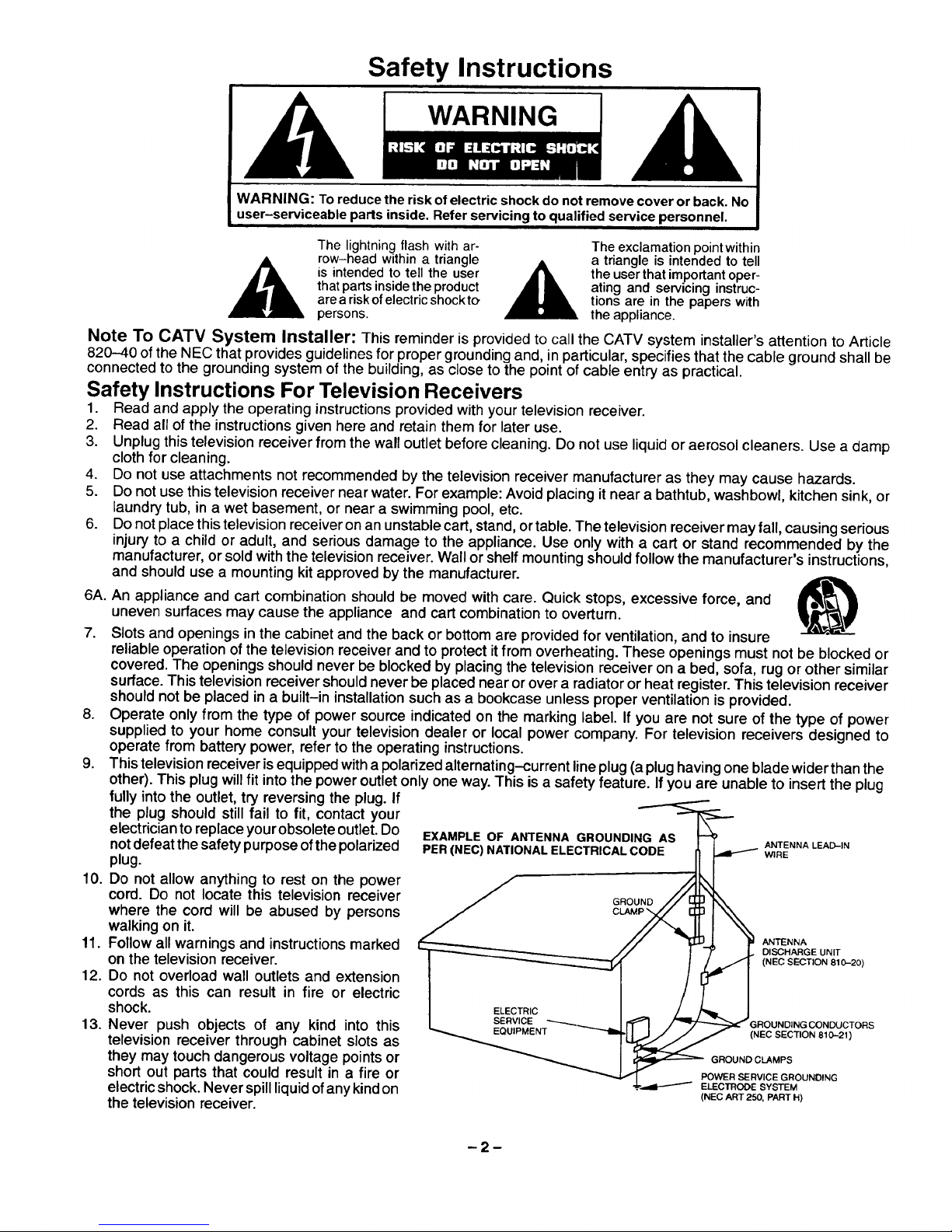
EXAMPLE OF ANTENNA GROUNDING AS _ ANT .......
PER (NEC) NATIONAL ELE WIRE
GROUND
// 1_l,IJ_J, I¥ ANTENNA
/ / J 7" _L DISCHARGE UNIT
I ELECTRIC _ / /_ I
SERVICE _ R N II _SE__V_'gE__ _ _1 _GI OU D NGCONDUCTORS
EQUIPMENT
_NT _-'-Ib _ (NEC SECTION 810_21 )
_ GROUND CLAMPS
POWER SERVICE GROUNDING
(NEC ART 250, PART FI)
14. Ifan outside antenna isconnected to the television equipment, be sure the antenna system is grounded so as to provide
some protection against voltage surges and built up static charges. In the U.S. Section 610 of the National Electrical
Code and in Canada Part 1of the Canadian Electrical Code provides information with respect to proper grounding of the
mast and supporting structure, grounding of the lead-in wire to an antenna discharge unit, size of grounding conductors,
location of antenna-discharge unit, connection to grounding electrodes, and requirements for the grounding electrode.
See Figure.
15. For added protection for this television receive rduring a lightning storm, orwhen itis left unattended and unused for long
periods of time, unplug it from the wall outlet a,nd disconnect the antenna. This will prevent damage tothe receiver due to
lightning and power-line surges.
16. An outside antenna system should not be located in the vicinity of overhead power lines or other electric light or power
circuits, or where it can fall into such power lines or circuits. When installing an outside antenna system extreme care
should be taken to keep from touching such power lines or circuits as contact with them might be fatal.
17. Unplug this television receiver from the wall outlet, and refer servicing to qualified service personnel under the following
conditions:
a. When the power cord or plug is damaged or frayed.
b. If liquid has been spilled into the television receiver.
c. If the television receiver has been exposed to rain or water.
d. If the television receiver does not ope rate normally by following the operating instructions. Adjust only those controls
that are covered by the ope rating instructions as improper adjustment of other controls may result indamage and will
often require extensive work by a qualified technician to restore the television receiver to normal operation.
e. If the television receiver has been dropped or the cabinet has been damaged.
f. When the television receiver exhibits a distinct change in performance- this indicates a need for service.
16. Do not attempt to service this television receiver yourself as opening or removing covers may expose you to dangerous
voltage or other hazards. Refer all servicing to qualified service personnel.
19. When replacement parts are required, be sure the service technician has used replacement parts specified by the
manufacturer that have the same characteristics as the original part. Unauthorized substitutions may result in fire,
electric shock, or other hazards.
20. Upon completion of any service or repairs to this television receiver, ask the service technician to perform routine safety
checks to determine that the television is in safe operating condition.
21. WARNING: To prevent fire or shock hazard, do not expose this appliance to rain or moisture.
22. CAUTION: TO PREVENT ELECTRIC SHOCK DO NOT USE THIS (POLARIZED) PLUG WITH AN RECEPTACLE OR
OTHER OUTLET UNLESS THE BLADES CAN BE FULLY INSERTED TO PREVENT BLADE EXPOSURE.
Important Information Regarding Use of Video Games, Computers, Teletext or Other Fixed Image Displays.
The extended use of fixed image program material can cause a permanent "shadow image" on the picture tube. This
background image isviewable on normal programs inthe form ofa stationary fixed image. This type of irreversible picture
tube deterioration can be limitedby observing the following steps:
A. Reduce the brightness/contrast settingto a minimum viewing level.
B. Do not display the fixed image for extended periods of time.
C. Turn the power off when not in actual use.
Power Source:
Channel Capability:
Video Input Jacks (2):
Audio Input Jacks (2):
To Audio AMP Jacks:
S-VHS Input Jack:
Picture in Picture:
Stereo Sound
Closed Caption Display
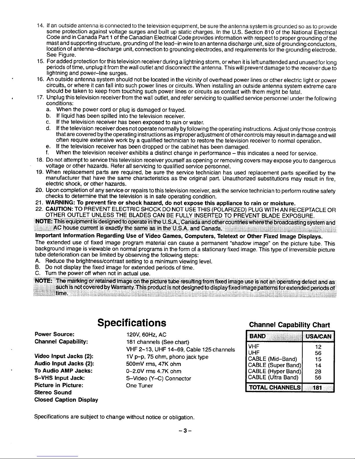
Specifications
120V, 60Hz, AC
181 channels (See chart)
VHF 2-13, UHF 14-69, Cable 125 channels
lV p-p, 75 ohm, phono jack type
500mV rms, 47K ohm
0-2.0V rms 4.7K ohm
S-Video (Y-C) Connector
One Tuner
Channel Capability Chart
VHF
UHF
CABLE (Mid-Band)
CABLE (Super Band)
CABLE (Hyper Band)i
CABLE (Ultra Band)
12
56
15
14
28
56
Specifications are subject to change without notice or obligation.
Introduction
Congratulations on Your New Purchase
Your new video component features an all solid state chassis which is designed to give you many years of enjoyment. It
was thoroughly tested and adjusted at the factory for best performance.
Inorder for you to take full advantage of your new video component, please read and follow the installation and operating
instructions supplied with this product.
Customer's Record
The model and serial number of this product may befound on its back cover. Youshould note the model and serial number
in the space provided and retain this book as a permanent record of your purchase to aid in identification in the event of
theft or loss.
Model Number: Serial Number:
Table of Contents
Safety Instructions ............................. 2
Specifications ................................. 3
Introduction ................................... 4
Installation .................................... 5
Receiver Location .............................. 5
Optional External Equipment Connections ......... 5
AC Power Supply Cord ......................... 5
Remote Control Battery Installation ............... 5
Antenna/Cable Connections ..................... 6
Standard Antenna and External Video Connection 7
No Cable Box or VCR .......................... 7
Cable Box .................................... 7
Cable Boxand VCR ............................ 8
Optional Equipment Connection and Operation .. 9
To Audio AMP Connection (stereo) .............. 9
Video/Audio Connection ........................ 9
Location of Controls (Receiver) ................ 10
Location of Controls (Remote) ................. 11
Remote Quick Reference Key Chart ............ 12
Control Operation ............................. 14
Power Button ................................. 14
Volume (Vol) Buttons .......................... 14
Mute Button .................................. 14
Channel (Ch) Buttons ......................... 14
Numeric Keypad .............................. 14
VCR Function Buttons ......................... 14
TV/Video Button .............................. 15
Recall Button ................................. 15
R-Tune (Rapid Tune) Button ................... 15
Multi Button .................................. 15
PIP (Picture inPicture) Button .................. 16
Swap Button ................................. 16
Size Button .................................. 16
Freeze Button ................................ 17
Move Button ................................. 17
Main Menu (Icons) ............................ 18
Language Set-up ............................. 18
Picture Adjustments ........................... 19
Picture Norm ............................... 19
Color ...................................... 19
Tint ....................................... 19
Brightness ................................. 19
Pictu re .................................... 19
Sharpness ................................. 19
Audio Adjustments ............................ 20
Audio Norm ................................ 20
Bass, Treble & Balance Adjustments .......... 20
Audio Mode (Stereo/SAP/Mono) ............. 21
AI Sound .................................. 21
TV Speakers ............................... 21
Lock (Game Guard) ........................... 22
Lock Game Guard .......................... 22
Unlock Game Guard ........................ 22
Channel Caption (Station Identifier) .............. 23
Timer Features ............................... 24
Sleep Timer ................................ 24
Program Timer ............................. 24
Set-Up Features .............................. 25
Set Time (Clock) ............................ 25
Antenna Tuning Mode ....................... 25
Auto Program .............................. 26
Manual Program ............................ 26
CC (Closed Caption) On Mute ................ 27
CC (Closed Caption) Mode ................... 27
English/Spanish/French Menu .................. 28
Programming The Universal Remote Control .... 29
VCR Infrared Codes Index ..................... 30
Cable Converter Box & CD Player Codes ........ 31
Cassette Players and AV Receivers Codes ...... 32
Laser Disc/DSS/TM/&DVD Codes ............... 33
Care & Cleaning ............................... 34
Power Loss ................................... 34
Troubleshooting Chart ........................ 35
Installation
Receiver Location
This unit is intended to be used with an optional stand or entertainment center. L;on_ultyour dealer for available upt=o==b.
Locate for comfortable viewing. Avoid placing where sunlight or other bright light (including reflections) will fall on the
screen.
Use of some types of fluorescent lighting can reduce remote control transmitter range.
Adequate ventilation is essential to prevent internal component failure. Keep away from areas of excessive heat or
moisture.
To insure optimum color purity do not position magnetic equipment (motors, fans, other speakers, etc.) nearby.
Optional External Equipment Connections
The Video/Audio connections between components can be made with shielded video and audio cables. For best perfor-
mance, video cables should utilize 75 ohm coaxial shielded wire. Cables are available from your dealer or electronic
supply house.
Before you purchase any cables, be sure you know what type of output and input con nectors you r various components
require. Also determine the length of cable you'll need.
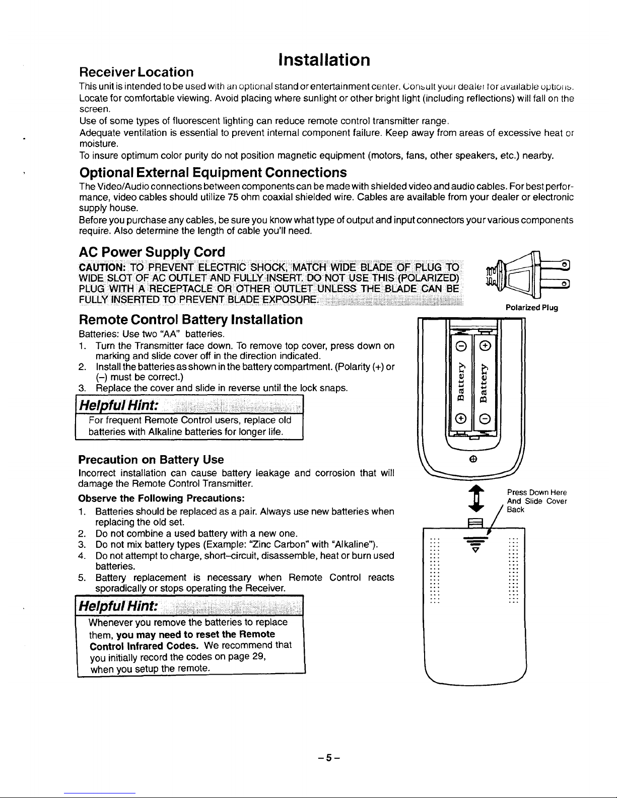
AC Power Supply Cord
Remote Control Battery Installation
Batteries: Use two "AA" batteries
1. Turn the Transmitter face down. To remove top cover, press down on
marking and slide cover off inthe direction indicated.
2. Install the batteries as shown in the battery compartment. (Polarity (+) or
(-) must be correct.)
3. Replace the cover and slide in reverse until the lock snaps.
" ° : : ........... I
h
HelpfulHint:
I
For frequent Remote Control users, replace old J
batteries with Alkaline batteries for longer life. I
Precaution on Battery Use
Incorrect installation can cause battery leakage and corrosion that will
damage the Remote Control Transmitter
Observe the Following Precautions:
1. Batteries should be replaced asa pair. Always use new batteries when
replacingthe old set
2 Do not combine a used battery with a new one
3 Do not mix battery types (Example: "Zinc Carbon" with "Alkaline").
4 Do not attempt to charge, short-circuit, disassemble, heat or burn used
batteries.
5 Battery replacement is necessary when Remote Control reacts
sporadically or stops operating the Receiver.
Whenever you remove the batteries to replace
them, you may need to reset the Remote
Control Infrared Codes. We recommend that
you initially record the codes on page 29,
when you setup the remote.
Polarized Plug
°,
• " V
Press Down Here
And Slide Cover
Back
.°
.°
.°
..
J
-5-
Antenna/CableConnections
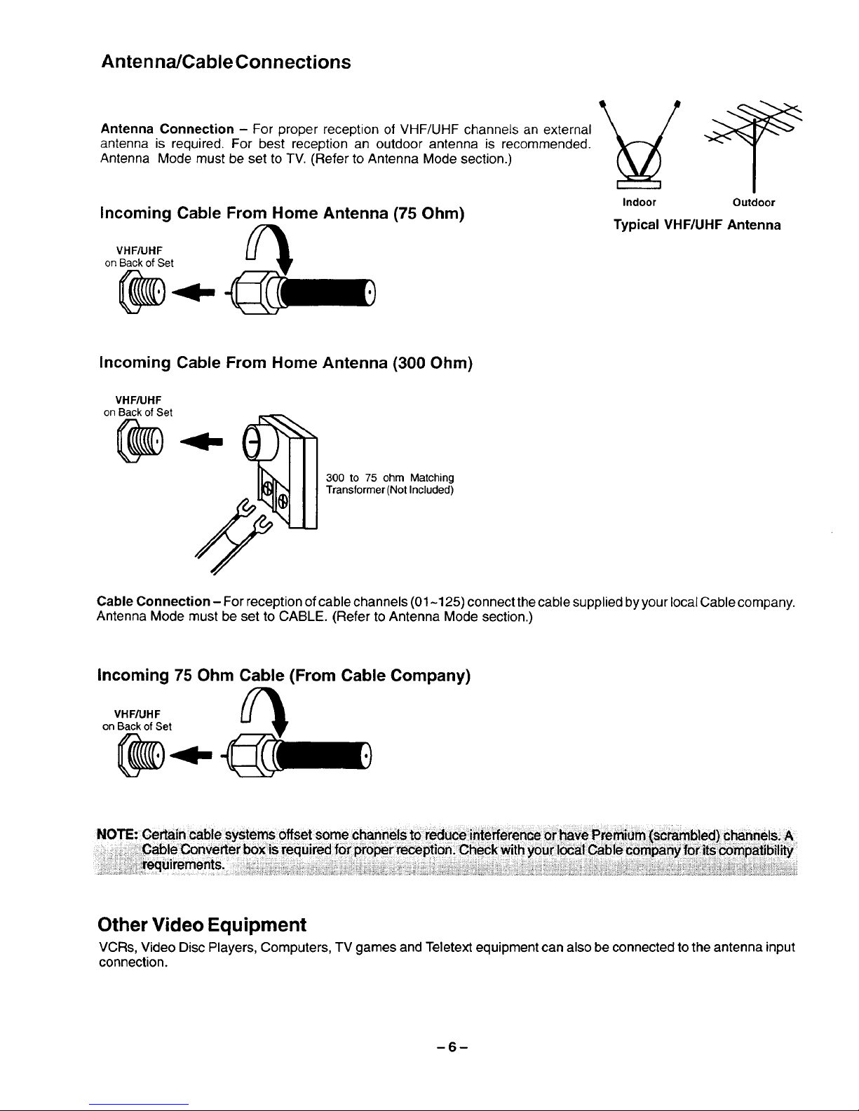
Antenna Connection - For proper reception of VHF/UHF channels an external
antenna is required. For best reception an outdoor antenna is recommended.
Antenna Mode must be set to TV. (Refer to Antenna Mode section.)
Incoming Cable From Home Antenna (75 Ohm)
VHF/UHF
on Back of Set
Indoor Outdoor
Typical VHF/UHF Antenna
Incoming Cable From Home Antenna (300 Ohm)
VHF/UHF
on Back of Set
300 to 75 ohm Matching
Transformer (Not Included)
Cable Connection - For reception of cable channels (01-125) connect the cable supplied byyour local Cable company.
Antenna Mode must be set to CABLE. (Refer to Antenna Mode section.)
Incoming 75 Ohm Cable (From Cable Company)
VHF/UHF
on Back of Set
NOTE:Certain cable systems offset some ChannblSto redu_ i_tefferenCe _ have Pre_ie_ (s_bl_)c_nnels A
C_le Converter box is required f0_ pto_r recepti05: Che_k _itb you_I_al Cabie_5_pa_ fo_its _atibil
Other Video Equipment
VCRs, Video DiscPlayers, Computers, TV games and Teletext equipmentcan also be connectedtothe antenna input
connection.
-6-
Standard Antenna and External Video Connection
The following illustrationsshow the standard antennaand video connections which can be used for most situations.
Note!his 1ReceiVe_h_s the PICTURE IN PICTURE! feature! Th{s allows yo£ to watch two (2) live broadcasts atthe
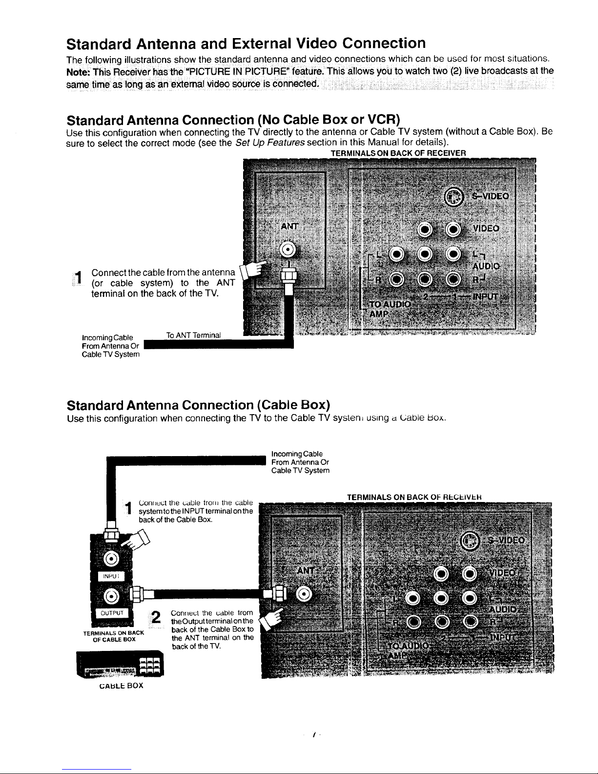
Standard Antenna Connection (No Cable Box or VCR)
Use this configuration when connectingthe TV directly to the antenna or Cable TV system (without a Cable Box). Be
sure to select the correct mode (see the Set Up Features section in this Manual for details).
TERMINALS ON BACK OF RECEIVER
1 Connectthe cable from the antenna
:_ (or cable system) to the ANT
terminal on the back of the TV.
Incoming Cable
From Antenna Or
Cable TV System
To ANT Terminal
Standard Antenna Connection (Cable Box)
Use this configuration when connecting the TV to the Cable TV systen_ using d L;able Idox.
Incoming Cable
From Antenna Or
Cable 77/System
Connect the cable trom the cable
systemto the INPUT terminal on the
back of the Cable Box.
TERMINALS ON BACK OF RECP..IVP.H
TERMINALS ON BACK
OF CABLE BOX
GAbLEBOX
Con_lect the cable trom
theOutput terminal on the
............. back of the Cable Box to
the ANT terminal on the
back ot the TV.
/ '
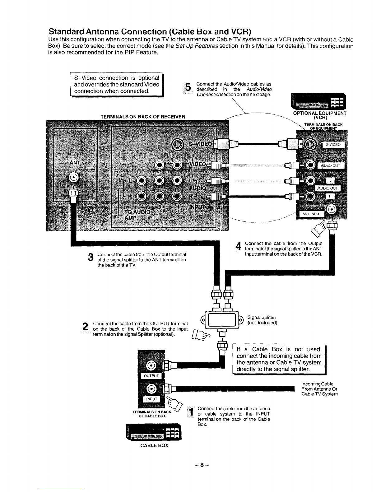
Standard Antenna Connection (Cable Box and VCR)
Use this configuration when connecting the TV to the antenna or Cable TV system and a VCR (with or without a Cable
Box). Be sure to select the correct mode (see the Set Up Features section in this Manual for details). This configuration
is also recommended for the PIP Feature.
S-Video connection is optional I
I
and overrides the standard Video
connection when connected.
I
\
TERMINALS ON BACK OF RECEIVER
;_! Connect the AudioNideo cables as
described in the Audio/Video
':__ Connectionsection on the next page.
OPTIONAL EQUIPMENT
(VCR)
TERMINALSON BACK
OF EQUIPMENT
ANltNPUT
Conneutthe cable front the Output terminal
of the signal splitter to the ANT terminal on
the back of the TV.
Connect the cable from the Output
terminalof the signal splitter tothe ANT
Input terminal on the back of the VCR.
Connect the cable from the OUTPUT terminal "'1 [
on the back of the Cable Box to the Input
............terminalon the signal Splitter (optional).
}}_) Signat bplitter
(not Included)
If a Cable Box is not used,
connect the incoming cable from
the antenna or Cable TV system
directly to the signal splitter.
Incoming Cable
From Antenna Or
Cable TV System
TERMINALS ON BACK
OF CABLE BOX
CABLE BOX
Connectthe cable irom the arltenna
.............or cable system to the INPUT
terminal on the back of the Cable
Box.
-8-
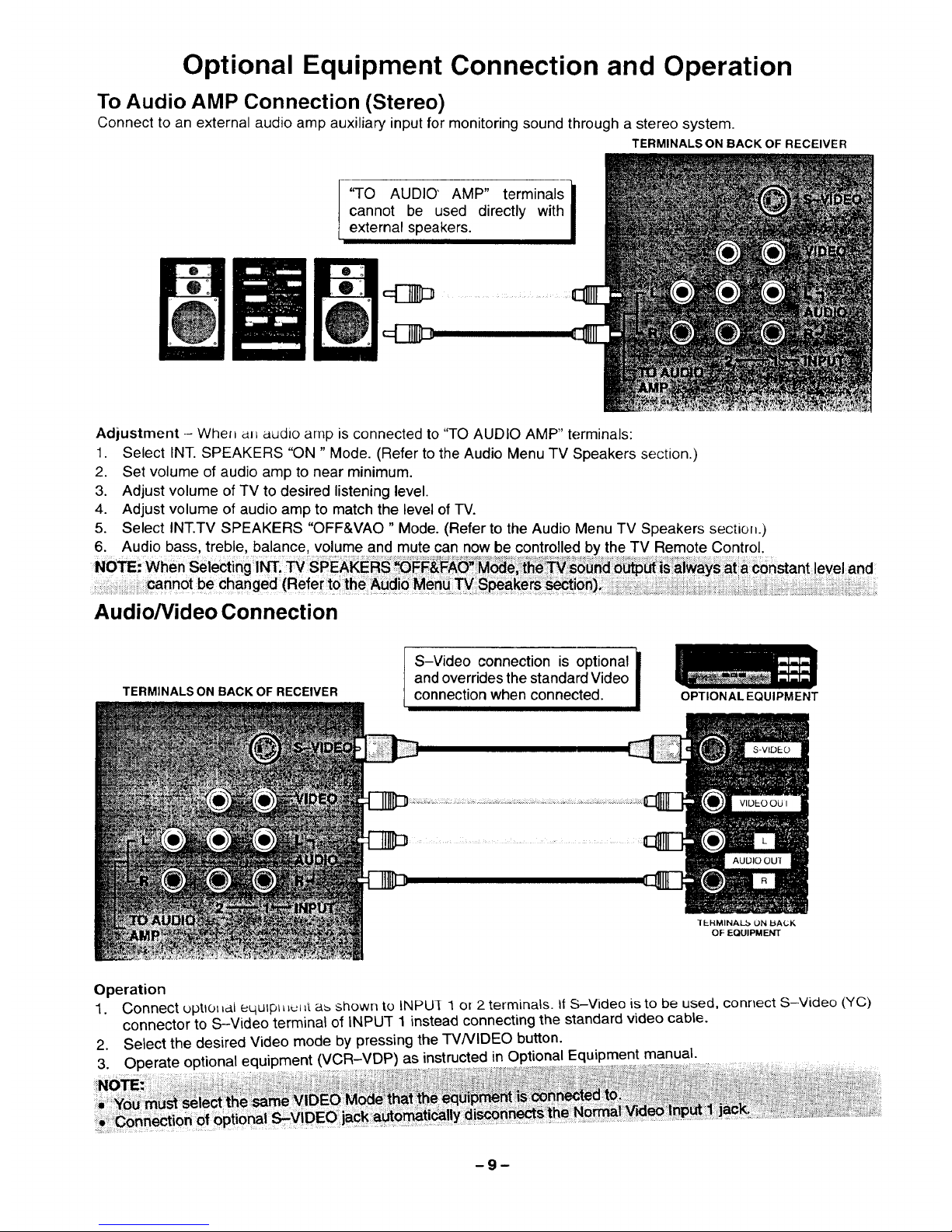
Optional Equipment Connection and Operation
To Audio AMP Connection (Stereo)
Connect to an external audio amp auxiliary input for monitoring sound through a stereo system.
TERMINALS ON BACK OF RECEIVER
7.
'q-o AUDIO' AMP" terminals l
cannot be used directly with
I
external speakers.
Adjustment- Whel= awl audio amp is connected to "TO AUDIO AMP _'terminals:
1. Select INT. SPEAKERS "ON " Mode. (Refer to the Audio Menu TV Speakers section.)
2. Set volume of audio amp to near minimum.
3. Adjust volume of TV to desired listening level.
4. Adjust volume of audio amp to match the level of TV.
5. Select INT.TV SPEAKERS "OFF&VAO" Mode. (Refer to the Audio Menu TV Speakers sectioll.)
6. Audio bass, treble, balance, volume and mute can now be controlled by the TV Remote Control.
Audio/Video Connection
TERMINALS ON BACK OF RECEIVER
6
S-Video connection is optional |
and overrides the standard Video
I
connection when connected.
OPTIONAL EQUIPMENT
IEHMINAL_ ON bA(.;K
OF EQUIPMENT
Operation
1. Connect uptlol=ai equtpl=_uL=t a_ shown to INPUI 1 or2 terminals. It S-Video is to be used, connect S-Video (YC)
connector to S-Video terminal of INPUT 1 instead connecting the standard video cable.
2. Select the desired Video mode by pressing the TVNIDEO button.
3. Operate optional equipment (VCR-VDP) as instructed in Optional Equipment manual.
-9-
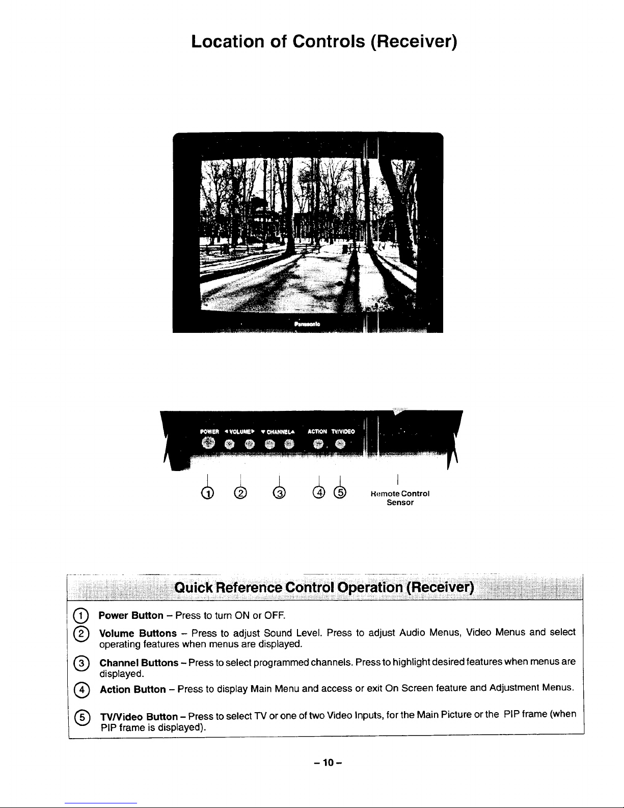
Location of Controls (Receiver)
Sensor
®
®
®
®
®
Power Button - Press to turn ON or OFE
Volume Buttons - Press to adjust Sound Level. Press to adjust Audio Menus, Video Menus and select
operating features when menus are displayed.
Channel Buttons - Press to select programmedchannels. Press to highlightdesired features when menus are
displayed.
Action Button - Press to display Main Menu and access or exit On Screen feature and Adjustment Menus.
TV/Video Button - Press toselect IV or one of two Video Inputs,for the Main Picture or the PIP frame (when
PIP frame is displayed).
-10-
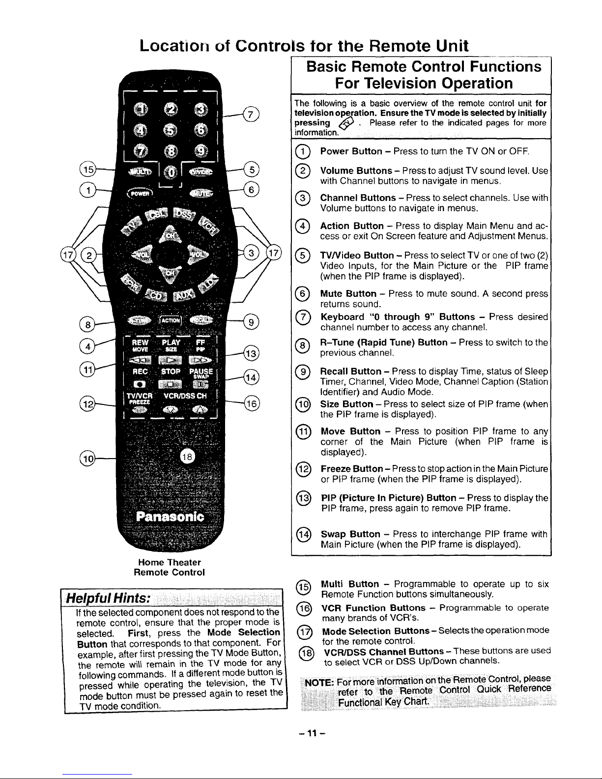
Location of ControLs tor the Remote Unit
Basic Remote Control Functions
For Television Operation
The following is a basic overview of the remote control unit for
television Ol_.ration. Ensure the TV mode is selected by initially
pressing _ , Please refer to the indicated pages for more
information. ....
®
@
@
®
@
Power Button - Press to turn the TV ON or OFF.
Volume Buttons - Press to adjust TV sound level. Use
with Channel buttons to navigate in menus.
Channel Buttons - Press to select channels. Use with
Volume buttons to navigate in menus.
Action Button - Press to display Main Menu and ac-
cess or exit On Screen feature and Adjustment Menus.
TV/Video Button - Press to select TV or one of two (2)
Video Inputs, for the Main Picture or the PIP frame
(when the PIP frame is displayed).
Mute Button Press to mute sound. A second
press
returns sound.
"0 9" Buttons - Press desired
Keyboard through
channel number to access any channel.
R-Tune (Rapid Tune) Button - Press to switch to the
previous channel.
®
®
@
®
®
@
Recall Button - Press to display Time, status of Sleep
Timer, Channel, Video Mode, Channel Caption (Station
Identifier) and Audio Mode.
Size Button - Press to select size of PIP frame (when
the PIP frame is displayed).
Move Button - Press to position PIP frame to any
corner of the Main Picture (when PIP frame is
displayed).
Freeze Button - Press to stop action inthe Main Picture
or PIP frame (when the PIP frame is displayed).
PIP (Picture In Picture) Button - Press to display the
PIP frame, press again to remove PIP frame.
Home "[heater
Remote Control
If the selected component does not respond to the
remote control, ensure that the proper mode is
selected. First, press the Mode Selection
Button that corresponds to that component. For
example, after first pressing the TV Mode Button,
the remote will remain in the TV mode _or any
following commands. If a different mode button is
pressed while operating the television, the TV
mode button must be pressed again to reset the
TV mode condition.
Button - Press to PIP frame with
Swap interchange
Main Picture (when the PIP frame is displayed).
@
®
@
@
Multi Button - Programmable to operate up to six
Remote Function buttons simultaneously.
VCR Function Buttons - Programmable to operate
many brands of VCR's.
Mode Selection Buttons- Selectsthe operation mode
for the remote control.
VCR/DSS Channel Buttons - These buttons are used
to select VCR or DSS Up/Down channels.
-11 -
 Loading...