

Panasonic CT-27G21 Owner’s Manual
Color Television
Operating Instructions
®
Read these instructions completely before operating this set.
Contents subject to change without notice or obligation.
Copyright 1996 by Matsushita Electric Corporation of America.
All rights reserved. Unauthorized copying and distribution is a violation of law.
00000 O0 (_
CT-27G21
PRINTED IN MEXICO
TQB2AA0040-1
Safety Instructions
WARNING
WARNING: Toreduce the risk ofelectric shock do not removecover or back. No
user-serviceable parts inside. Refer servicingto qualified servicepersonnel.
i
The lightning flash with ar-
is intended to tell the user
_ row-head within a triangle _
that parts inside the product
are a risk ofelectric shock to
persons.
Note To CATV System Installer: This reminder is provided to call the CATV system installer's attention to Article
820-40 of the NEC that provides guidelines for proper grounding and, in particular, specifies that the cable ground shall be
connected to the grounding system of the building, as close to the point of cable entry as practical.
Safety Instructions For Television Receivers
1. Read and apply the operating instructions provided with your television receiver.
2. Read all of the instructions given here and retain them for later use.
3. Unplug this television receiver from the wall outlet before cleaning. Do not use liquid or aerosol cleaners• Use a damp
cloth for cleaning.
4. Do not use attachments not recommended by the television receiver manufacturer as they may cause hazards.
5. Do not use this television receiver near water. For example: Avoid placing it near a bathtub, washbowl, kitchen sink, or
laundry tub, in a wet basement, or near a swimming pool, etc.
6. Do not place this television receiver on an unstable cart, stand, or table. The television receiver may fall, causing serious
injury to a child or adult, and serious damage to the appliance. Use only with a cart or stand recommended by the
manufacturer, or sold with the television receiver. Wall or shelf mounting should follow the manufacturer's instructions,
and should use a mounting kit approved by the manufacturer.
6Ao An appliance and cart combination should be moved with care. Quick stops, excessive force, and
uneven surfaces may cause the appliance and cart combination to overturn.
7. Slots and openings in the cabinet and the back or bottom are provided for ventilation, and to insure
reliable operation of the television receiver and to protect it from overheating. These openings must not be blocked or
covered. The openings should never be blocked by placing the television receiver on a bed, sofa, rug or other similar
surface. This television receiver should never be placed near or over a radiator or heat register. This television receiver
should not be placed in a built-in installation such as a bookcase unless proper ventilation is provided.
8. Operate only from the type of power source indicated on the marking label. If you are not sure of the type of power
supplied to your home consult your television dealer or local power company. For television receivers designed to
operate from battery power, refer to the operating instructions.
9. This television receiver is equipped with a polarized alternating--current line plug (a plug having one blade widerthan the
other). This plug will fit into the power outlet only one way. This is a safety feature. If you are unable to insert the plug
The exclamation point within
a triangle is intended to tell
the user that important oper-
ating and servicing instruc-
tions are in the papers with
the appliance.
the plug should still fail to fit, contact your
fully into the outlet, try reversing the plug. If N_G AS'_
electrician toreplace yourobsolete outlet. Do EXAMPLE OF ANTENNA GROUNDI ANTENNALEAD-IN
not defeat the safety purpose ofthe polarized PER(NEC)NATIONALELECTRICALCODE _ _ W_RE
plug.
10. Do not allow anything to rest on the power
cord. Do not locate this television receiver GROUND// U_ IX\
where the cord will be abused by persons CLAMP'>/--K/ D_J J __
walking on it.
11. Follow all warnings and instructions marked ANTENNA
DISCHARGE UNIT
on the television receiver, (NEC SECTION810-20)
12. Do not overload wall outlets and extension
cords as this can result in fire or electric
shock.
13. Never push objects of any kind into this L......_ %_V_CENT_ _-..-J_ /',i_..L -_ /_T-J /_._ GROUNDINGCONDUCTORS(NECSECTION 610-21)
television receiver through cabinet slots as
they may touch dangerous voltage points or GROUNDCLAMPS
short out parts that could result in a fire or POWERSERVICEGROUNDING
• ELECTRODE SYSTEM
electric shock. Never spill liquid ofany kind on (NEC ART250,PARTH)
the television receiver.
-2-
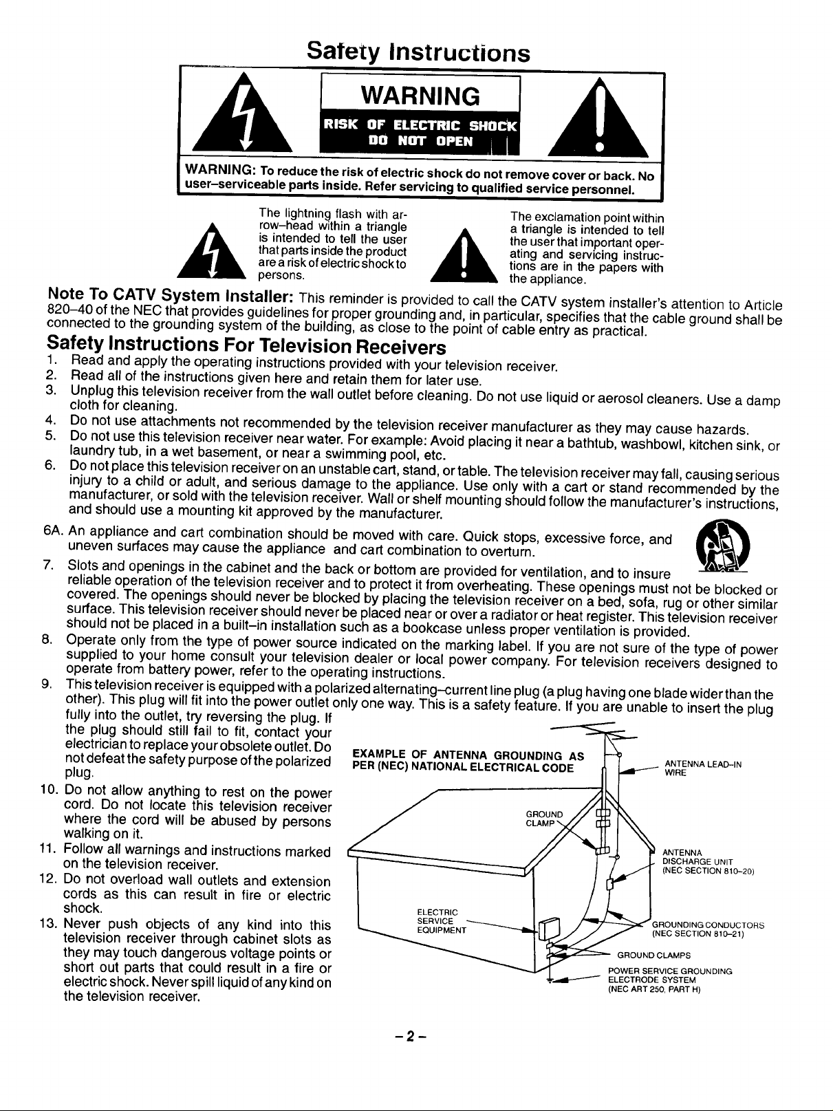
14. if an outside antenna is connected to the television equipment, be sure the antenna system is grounded so as to provide
some protection against voltage surges and built up static charges. In the U.S. Section 810 of the National Electrical
Code and in Canada Part I of the Canadian Electrical Code provides information with respect to proper grounding of the
mast and supporting structure, grounding ofthe lead-in wire to an antenna discharge unit, size of grounding conductors,
location of antenna-discharge unit, connection to grounding electrodes, and requirements for the grounding electrode.
See Figure.
15. For added protection for this television receiver during a lightning storm, or when it is left unattended and unused for long
periods of time, unplug itfrom the wall outlet and disconnect the antenna. This will prevent damage to the receiver due to
lightning and power-line surges.
16. An outside antenna system should not be located in the vicinity of overhead power lines or other electric light or power
circuits, or where it can fall into such power lines or circuits. When installing an outside antenna system extreme care
should be taken to keep from touching such power lines or circuits as contact with them might be fatal.
17. Unplug this television receiver from the wall outlet, and refer servicing to qualified service personnel under the following
conditions:
a. When the power cord or plug is damaged or frayed.
b. If liquid has been spilled into the television receiver.
c. Ifthe television receiver has been exposed to rain or water.
d. Ifthe television receiver does not operate normally by following the operating instructions. Adjust only those controls
that are covered by the operating instructions as improper adjustment of other controls may result in damage and will
often require extensive work by a qualified technician to restore the television receiver to normal operation.
e. If the television receiver has been dropped or the cabinet has been damaged.
f. When the television receiver exhibits a distinct change in performance - this indicates a need for service.
18. Do not attempt to service this television receiver yourself as opening or removing covers may expose you to dangerous
voltage or other hazards. Refer all servicing to qualified service personnel.
19. When replacement parts are required, be sure the service technician has used replacement parts specified by the
manufacturer that have the same characteristics as the original part. Unauthorized substitutions may result in fire,
electric shock, or other hazards.
20. Upon completion of any service or repairs to this television receiver, ask the service technician to perform routine safety
checks to determine that the television is in safe operating condition.
21. WARNING: To prevent fire or shock hazard, do not expose this appliance to rain or moisture.
22. CAUTION: TO PREVENT ELECTRIC SHOCK DO NOT USE THIS (POLARIZED) PLUG WITH AN RECEPTACLE OR
OTHER OUTLET UNLESS THE BLADES CAN BE FULLY INSERTED TO PREVENT BLADE EXPOSURE.
NOTE: This equipment isdesigned tooperate inthe U.S.A., Canada and othercountries where the broadcasting system and
AC house current is exactly the same as in the U.S.A. and Canada.
Important Information Regarding Use of Video Games, Computers, Teletext or Other Fixed Image Displays.
The extended use of fixed image program material can cause a permanent "shadow image" on the picture tube. This
background image is viewable on normal programs in the form of a stationary fixed image. This type of irreversible picture
tube deterioration can be limited by observing the following steps:
A. Reduce the brightness/contrast setting to a minimum viewing level.
B. Do not display the fixed image for extended periods of time.
C. Turn the power off when not in actual use.
NOTE: The marking or retained image on the picture tube resulting from fixed image use is not an operating defect and as
such is not covered by Warranty. This product isnot designed to display fixed image patterns for extended periods of
time.
Specifications
Power Source:
Channel Capability:
Video Input Jack:
Audio input Jacks:
To Audio AMP Jacks:
Stereo Sound
Closed Caption Display
Picture in Picture:
Specifications are subject to change without notice or obligation.
120V, 60Hz, AC
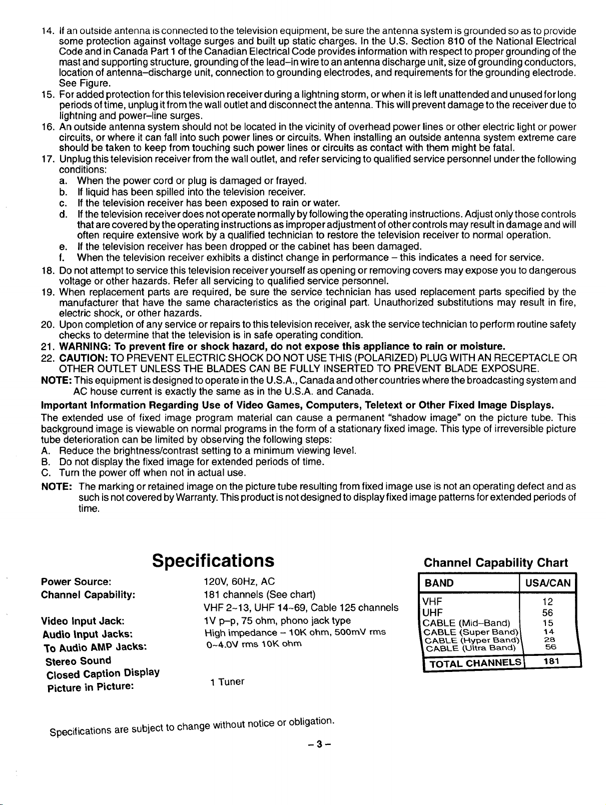
181 channels (See chart)
VHF 2-13, UHF 14-69, Cable 125 channels
lV p-p, 75 ohm, phono jack type
High impedance - 10K ohm, 500mY rms
O-4.0V rms 1OK ohm
1 Tuner
m3_
Channel Capability Chart
BAND
VHF
UHF
CABLE (.Mid-Band)
CABLE (Super Band)
CABLE (Nyper Bandy
CABLE (,Ultra Band)
TOTAL CHANNELS
USA/CAN
12
56
15
14
28
56
181
introduction
;uf gratulations on Your New Purchase
Your t_ewvJcleuuu+_punent teatures an all solid state chassis which is designed to give you many years of enjoyment. It
was thoroughly tested and adjusted at the factory for best performance.
Inorder for you to take full advantage of your new video component, please read and follow the installation and operating
instructions supplied with this product.
Customer's Record
The model and serial number of this product may be found on itsback cover. You should note the model and serial number
in the space provided and retain this book as a permanent record of your purchase to aid in identification in the event of
theft or loss.
Model Number: Serial Number:
Table of Contents
Safety Instructions ............................. 2
Specifications ................................. 3
Introduction ................................... 4
Care and Cleaning ............................. 5
Installation .................................... 6
Receiver Location .............................. 6
Optional External Equipment Connections ......... 6
AC Power Supply Cord ......................... 6
Remote Control Battery Installation ............... 6
Antenna/Cable Connections ..................... 7
PIP External Video and Antenna Connection ....... 8
Optional Equipment Connection and Operation .. 9
To Audio AMP Connection (stereo) .............. 9
Video/Audio Connection ........................ 9
Location of Controls (Receiver) ................ 10
Location of Controls (Remote) ................. 11
Basic Remote Functions ....................... 11
Remote Quick Reference Key Chart ............ 12
Control Operation ............................. 14
Power Button ................................. 14
Volume (Vol) Buttons .......................... 14
Mute Button .................................. 14
Channel Change Features ..................... 14
Channel (Ch) Buttons ....................... 14
Keyboard "0 through 9" Buttons ............... 14
VCR Function Buttons ......................... 14
TV/Video Button .............................. 15
Recall Button ................................. 15
R-Tune (Rapid Tune) Button ................... 15
Multi Button .................................. 15
PiP (Picture in Picture) Button .................. 16
Swap Button ................................. 16
Size Button .................................. 16
Freeze Button ................................ 17
Move Button ................................. 17
Main Menu (Icons) ............................ 18
Picture Adjustments ........................... 19
Picture Norm ............................... 19
Color ...................................... 19
Tint ....................................... 19
Brightness ................................. 19
Picture .................................... 19
Sharpness ................................. 19
Audio Adjustments ............................ 20
Mode (Stereo/SAP/Mono) ................... 20
AI Sound .................................. 21
Lock ........................................ 22
Lock Game Guard .......................... 22
Unlock Game Guard ........................ 23
Channel Caption (Station Identifier) .............. 24
Timer Features ............................... 25
Sleep Timer ................................ 25
Program Timer ............................. 26
Set-Up Features .............................. 27
Set Time (Clock) ............................ 27
Ant (Antenna) .............................. 28
Auto Prog (Program) ........................ 29
Manual Prog (Program) ...................... 30
CC (Closed Caption) On Mute ................ 31
CC (Closed Caption) Mode ................... 32
Trilingual Menu Selection ...................... 33
Programming The Universal Remote Control .... 34
VCR Infrared Codes Index ..................... 35
Cable Converter Box & CD Player Codes ........ 36
Cassette Players and AM Receivers Codes ...... 37
Laser Disc/DSS/TV/&DVD Codes ............... 38
Troubleshooting Chart ........................ 39
Power Loss ................................... 39
-4-
Care and Cleaning
Picture lube (,]urn set off)
Use a mild soap solution or window cleaner and a clean cloth. DO NOT USE ABRASIVE CLEANERS. Avoid excessive
moisture and wipe dry.
Plastic Cabinets
Wipe the cabinet with a soft cloth dampened with water or a mild detergent solution and wipe dry with a soft clean cloth.
Avoid excessive moisture. Do not use benzene, thinners or other petroleum based cleaners.
Wood Cabinets
When dusting or polishing the cabinet, use a clean soft cloth and stroke straight with the grain. An occasional coat of
furniture polishwilt help preserve the finish. Do not use benzene, thinners or other petroleum based cleaners. Do not
place objects made ofplastic or rubberdirectly on top ofthe cabinet. A chemical reaction could resultcausing permanent
marring of the finish.
Remote Control Transmitter
Do notuse benzene, thinners orother petroleum based cleaners toclean the Remote Control Transmitter. Toclean, wipe
with a soft cloth slightly moistened with a mild detergent and then wipe drywith a soft clean cloth.
-5-
Installation
Receiver Locatiol=
This unit is intended to be used withaL,opuonat stand or entertainment center. C;uf_sultyour dealer for available options.
Locate for comfortable viewing. Avoid placing where sunlight or other bright light (including reflections) will fall on the
screen.
Use of some types of fluorescent lighting can reduce remote control transmitter range.
Adequate ventilation is essential to prevent internal component failure. Keep away from areas of excessive heat or
moisture.
To insure optimum color purity do not position magnetic equipment (motors, fans, other speakers, etc.) nearby.
Optional External Equipment Connections
The Video/Audio connections between components can be made with shielded video and audio cables. For best perfor-
mance, video cables should utilize 75 ohm coaxial shielded wire. Cables are available from your dealer or electronic
supply house.
Before you purchase any cables, be sure you know what type of output and input connectors your various components
require. Also determine the length of cable you'll need.
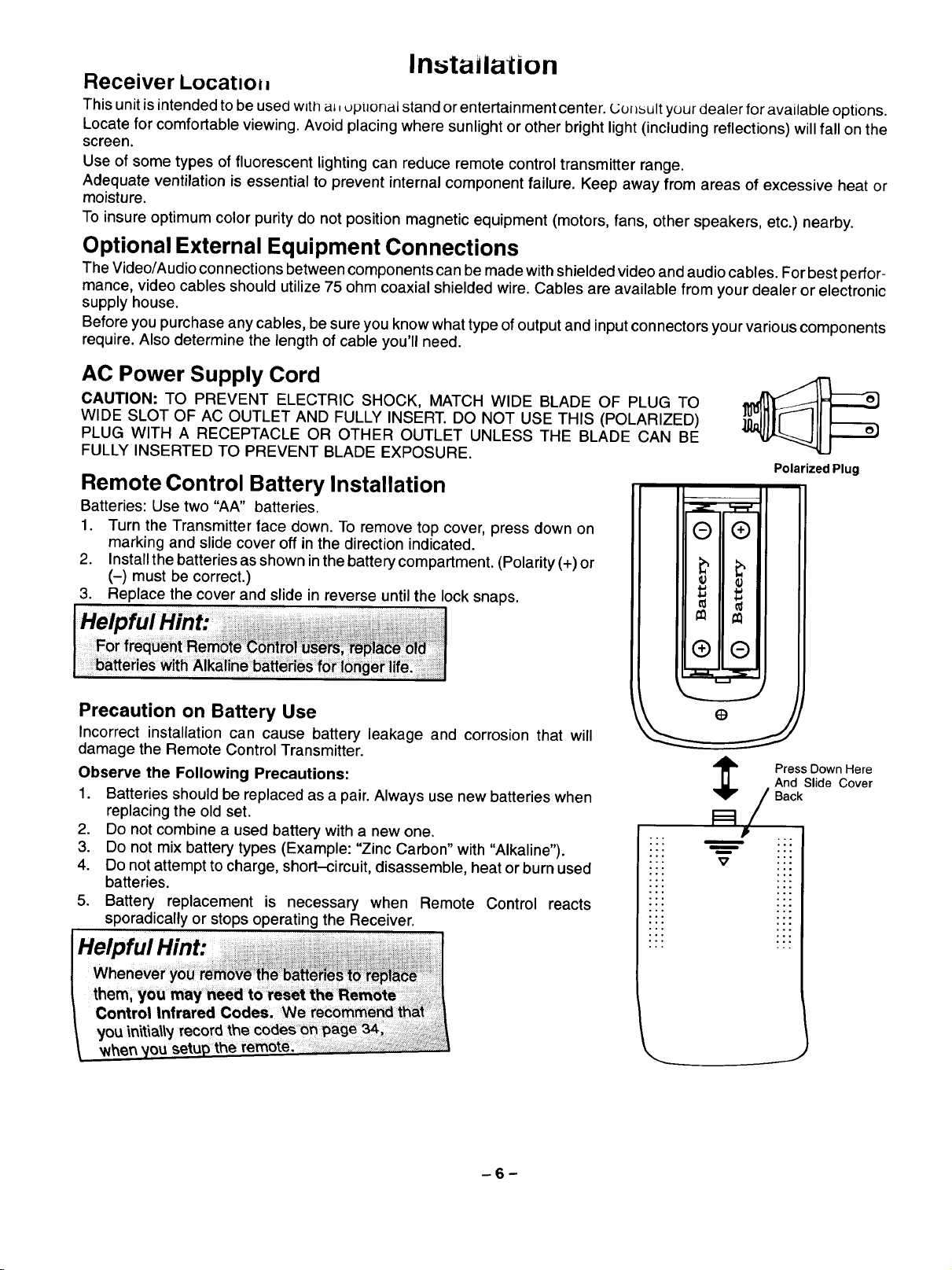
AC Power Supply Cord
CAUTION: TO PREVENT ELECTRIC SHOCK, MATCH WIDE BLADE OF PLUG TO
WIDE SLOT OF AC OUTLET AND FULLY INSERT. DO NOT USE THIS (POLARIZED)
PLUG WITH A RECEPTACLE OR OTHER OUTLET UNLESS THE BLADE CAN BE
FULLY INSERTED TO PREVENT BLADE EXPOSURE.
Polarized Plug
Remote Control Battery Installation
Batteries: Use two "AA" batteries.
1. Turn the Transmitter face down. To remove top cover, press down on
marking and slide cover off in the direction indicated.
2. Install the batteries as shown in the battery compartment. (Polarity (+) or
(-) must be correct.)
3. Replace the cover and slide in reverse until the lock snaps.
Precaution on Battery Use
Incorrect installation can cause battery leakage and corrosion that will
damage the Remote Control Transmitter.
Observe the Following Precautions:
1. Batteries should be replaced as a pair. Always use new batteries when
replacing the old set.
2. Do not combine a used battery with a new one.
3. Do not mix battery types (Example: "Zinc Carbon" with "Alkaline").
4. Do not attempt to charge, short-circuit, disassemble, heat or burn used
batteries.
5. Battery replacement is necessary when Remote Control reacts
sporadically or stops operating the Receiver.
Helpful Hint:
Press Down Here
And Slide Cover
Back
m
m
..
°.
\
-6-
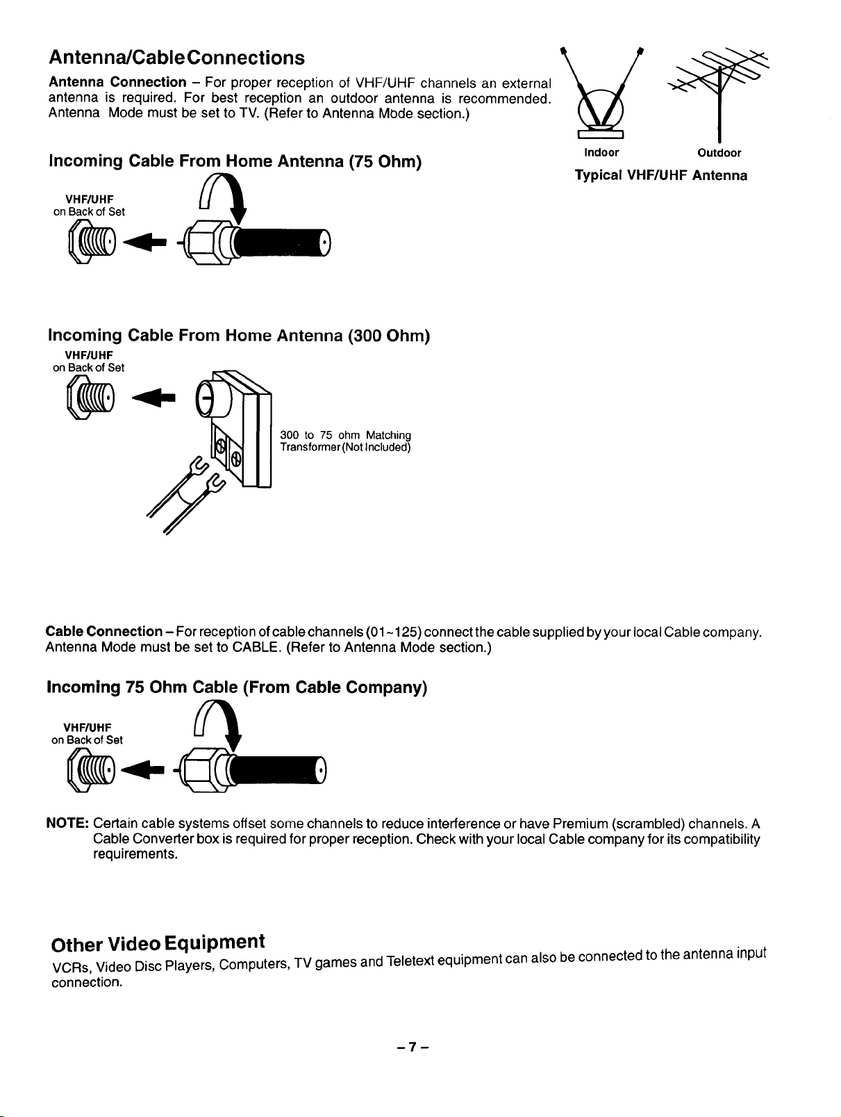
Antenna/Cable Connections
Antenna Connection - For proper reception of VHF/UHF channels an external
antenna is required. For best reception an outdoor antenna is recommended.
Antenna Mode must be set to TV. (Refer to Antenna MOde section.)
Incoming Cable From Home Antenna (75 Ohm)
VHF/UHF
on Back of Set
Incoming Cable From Home Antenna (300 Ohm)
VHF/UHF
onBackofSet
300 to 75 ohm Matching
Transformer(Not Included)
Indoor Outdoor
Typical VHF/UHF Antenna
Cable Connection - For reception of cable channels (01 ~125) connect the cable supplied by your local Cable company.
Antenna Mode must be set to CABLE. (Refer to Antenna Mode section.)
Incoming 75 Ohm Cable (From Cable Company)
VHFIUHF
on Back of Set
NOTE: Certain cable systems offset some channels to reduce interference or have Premium (scrambled) channels. A
Cable Converter box is required for proper reception. Check with your local Cable company for its compatibility
requirements.
Other Video Equipment
VCRs, Video Disc Players, Computers, TV games and Teletext equipment can also be connected to the antenna input
connection.
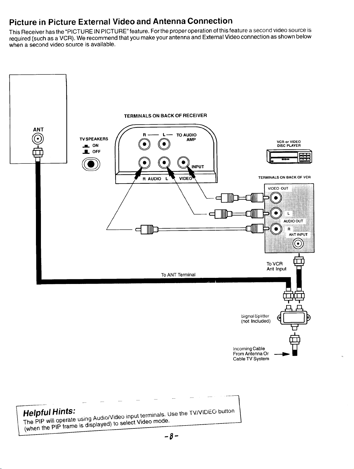
Picture in Picture External Video and Antenna Connection
This Receiver has the "PICTURE IN PICTURE" feature. For the proper operation of this feature asecond video source is
required (such as a VCR). We recommend that you make your antenna and External Video connection as shown below
when a second video source is available.
TERMINALS ON BACK OF RECEIVER
ANT
TV SPEAKERS AMP
I1= ON
JL OFF
_'_ __-- TO AUDIO
UDI
To ANT Terminal
VCR or VIDEO
DISC PLAYER
TERMINALS ON BACK OF VCR
ToVCR
Ant Input
T------
HelpfulHints:
piP/ Nillo erate using AudioNideo input terminals. Use the TVNIDEO button
q'he .... _P .... {=,4 nlaved_ to select Video mode.
__ (.when the t-it -,=,,,= ,-, _ls_. , .
A_
Signal Splitter
(not Included)
Incoming Cable
From Antenna Or
Cable TV System
\
l
Optional Equipment Connection and Operation
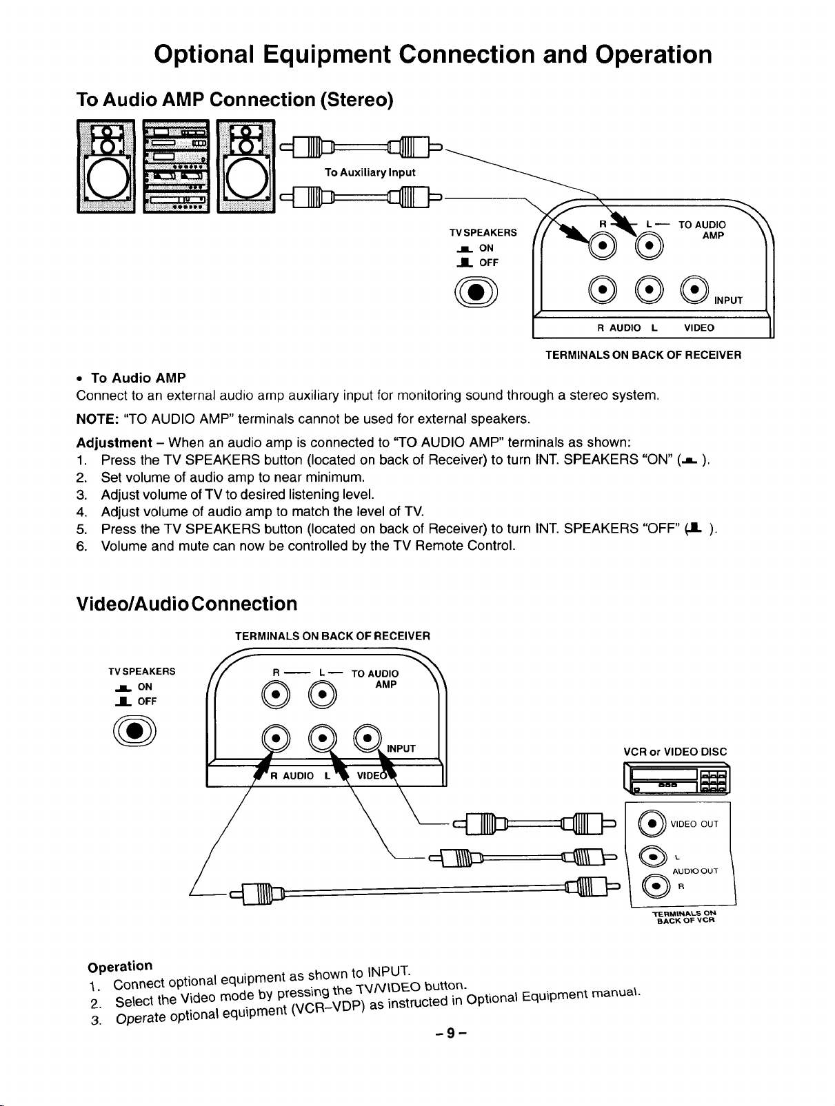
To Audio AMP Connection (Stereo)
To Auxiliary Input
\
TV SPEAKERS
ON
OFF
R,uo,o _ _ 11
TERMINALS ON BACK OF RECEIVER
• To Audio AMP
Connect to an external audio amp auxiliary input for monitoring sound through a stereo system.
NOTE: "TO AUDIO AMP" terminals cannot be used for external speakers.
Adjustment - When an audio amp is connected to "TO AUDIO AMP" terminals as shown:
1. Press the TV SPEAKERS button (located on back of Receiver) to turn INT. SPEAKERS "ON" (,,,).
2. Set volume of audio amp to near minimum.
3. Adjust volume of TV to desired listening level.
4. Adjust volume of audio amp to match the level of TV.
5. Press the TV SPEAKERS button (located on back of Receiver) to turn INT. SPEAKERS "OFF" (JL).
6. Volume and mute can now be controlled by the TV Remote Control.
Video/Audio Connection
TERMINALS ON BACK OF RECEIVER
TVSPEAKERS R_ L_ TO AUDIO
II OFF
R AUDIO L
Operation
1. Connect optional equipment as shown to INPUT.
2. Select the Video mode by pressingthe TV/VIDEO button.
3. Operate optional equipment (VCR-VDP) as instructed in Optional Equipment manual
--9--
VCR or VIDEO DISC
_) VIDEO OUT
L
) AUDIO OUT
i
"t"F_.R_RINIALS ON
BACK OF VCR
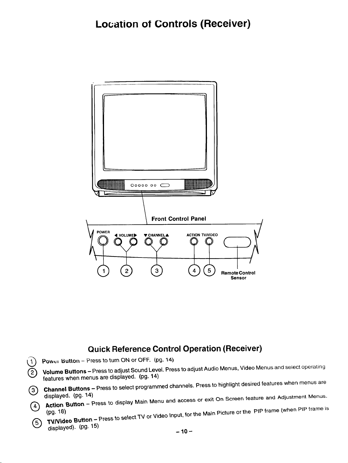
Location of Controls (Receiver)
0oooo oo CZ_
• VOLUMEIb • CNANNEL& ACTION TV/VIDEO
R Front Control Panel __
\(_ ? ? _ _ RemotsControl
Sensor
Quick Reference Control Operation (Receiver)
Powul Button - Press to turn ON or OFF. (,pg. 14)
Volume Buttons - Press to adjust Sound Level. Pressto adjust Audio Menus, Video Menus and select operating
®
features when menus are displayed. (pg. 14)
Channel Buttons - Press to select programmed channels. Press to highlight desired features when menus are
®
displayed. (pg. 14)
_ct_on Button - Press to d_sp_ayMa_n Menu and access or exit On Screen _eature and /kdiustment Menus.
®
(pg._8)
3"V/Video Button - Press to select TV or Video input, for the Main Picture or the PIP frame (when PIP trame is
®
displayed). (Pg. 15)
-10-
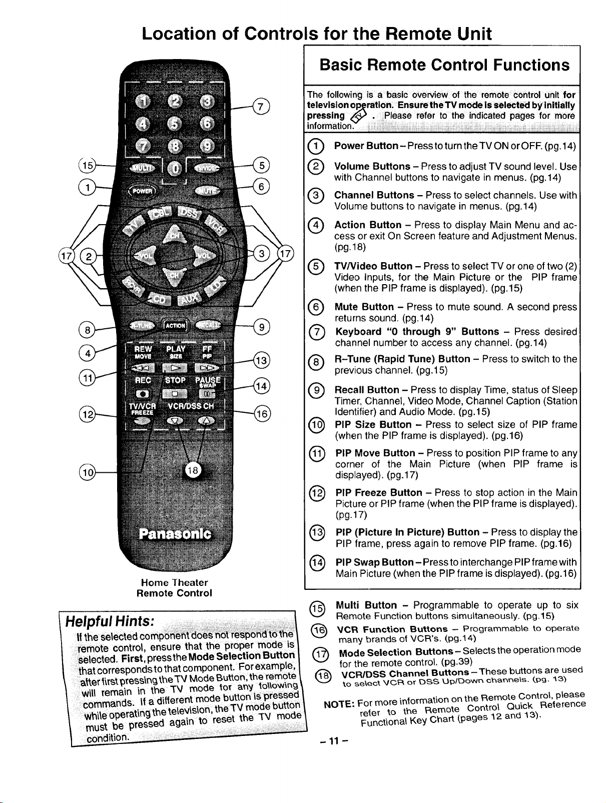
Location of Controls for the Remote Unit
Basic Remote Control Functions
The following is a basic oVerview of the remote control unit for
Power Button - Press to turn the TV ON orOFF. (pg.14)
®
Volume Buttons - Press toadjust TV sound level. Use
@
with Channel buttons to navigate in menus. (pg.14)
Channel Buttons - Press to select channels. Use with
@
Volume buttons to navigate in menus. (pg.14)
Action Button - Press to display Main Menu and ac-
@
cess or exit On Screen feature and Adjustment Menus.
(pg.18)
TV/Video Button - Press to select TV or one of two
Video Inputs, for the Main Picture or the PIP frame
(when the PIP frame is displayed). (pg.15)
Mute Button Press to mute sound. A second
returns sound. (pg.14)
Keyboard through
channel number to access any channel. (pg.14)
R-Tune (Rapid Tune) Button - Press to switch to the
®
previous channel. (pg.15)
Recall Button - Press to display Time, status of Sleep
®
Timer, Channel, Video Mode, Channel Caption (Station
Identifier) and Audio Mode. (pg.15)
PIP Size Button - Press to select size of PIP frame
®
(when the PIP frame is displayed). (pg.16)
PIP Move Button - Press to position PIP frame to any
®
corner of the Main Picture (when PIP frame is
displayed). (pg.17)
PIP Freeze Button - Press to action in the Main
Picture or PIP frame (when the PIP frame is displayed).
(pg.17)
PIP (Picture In Picture) Button - Press to display the
@
PIP frame, press again to remove PIP frame. (pg.16)
"0 9" Buttons Press desired
stop
(2)
press
Home lheater
Remote Control
PIP Swap Button - Press to interchange PIP frame with
®
Main Picture (when the PIP frame is displayed). (pg.16)
Multi Button - Programmable to operate up to six
@
Remote Function buttons simultaneously. (pg.15)
VCR Function Buttons - Programmable to operate
®
many brands o_VCR's. (pg.14)
Mode Selection Buttons- Selects the operation mode
@
for the remote control. (pg.39)
VCPJDSS Channel Buttons- These buttons are used
®
to _e\ect _/C,F_ or E)SS Up/E)o',Nn c_a_nets. (.pg- 137
NOTE.: For more information on the Remote Control, please
-11 -
reier to the Remote Control Quick Reference
Functional Key Chart (,pages 12 and 13).
®®®
®®®
®®®
®
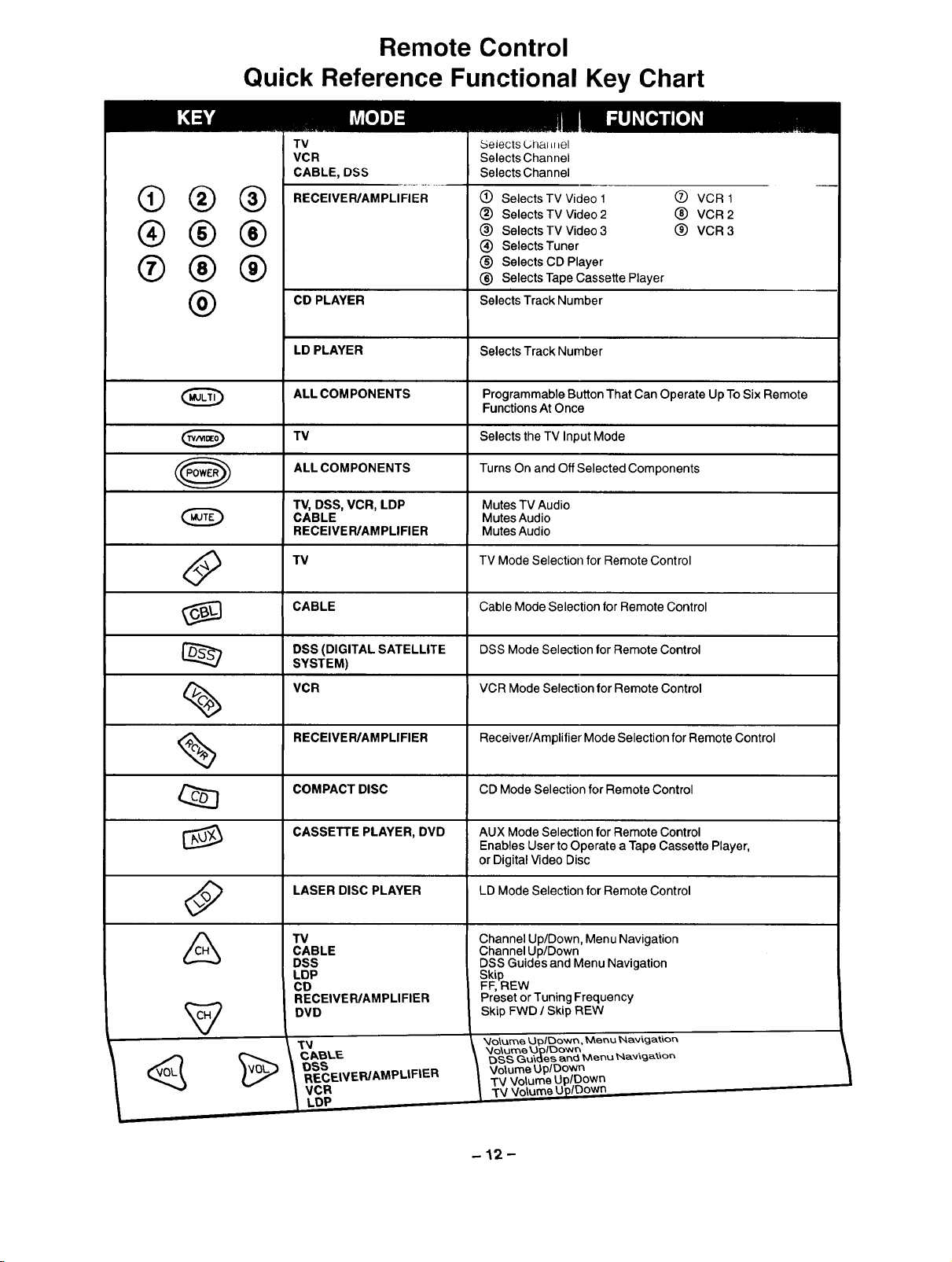
Remote Control
Quick Reference Functional Key Chart
TV Selects L;ha_=f=el
VCR Selects Channel
CABLE, DSS Selects Channel
RECEIVER/AMPLIFIER (_ Selects TV Video 1
Selects TV Video 2
(_) Selects TV Video 3
(_) Selects Tuner
(_) Selects CD Player
(_) Selects Tape Cassette Player
CD PLAYER
Selects Track Number
Q VCR 1
_) VCR 2
(_) VCR 3
@
O
%
%
LD PLAYER
ALL COM PONENTS
TV
ALL COMPONENTS
TV, DSS, VCR, LDP
CABLE
RECEIVER/AMPLIFIER
TV
CABLE Cable Mode Selection for Remote Control
DSS (DIGITAL SATELLITE DSS Mode Selection for Remote Control
SYSTEM)
VCR VCR Mode Selection for Remote Control
RECEIVER/AMPLIFIER Receiver/Amplifier Mode Selection for Remote Control
COMPACT DISC CD Mode Selection for Remote Control
Selects Track Number
Programmable Button That Can Operate Up To Six Remote
Functions At Once
Selects the TV Input Mode
Turns On and Off Selected Components
Mutes TV Audio
Mutes Audio
Mutes Audio
TV Mode Selection for Remote Control
W
CASSETTE PLAYER, DVD AUX Mode Selection for Remote Control
LASER DISC PLAYER LD Mode Selection for Remote Control
TV
CABLE
DSS
LDP
CD
RECEIVER/AMPLIFIER
DVD
RECEIVER/AMPLIFIER
t vcB
Enables User to Operate a Tape Cassette Player,
or Digital Video Disc
Channel Up/Down, Menu Navigation
Channel Up/Down
DSS Guides and Menu Navigation
Skip
FF, REW
Preset or Tuning Frequency
Skip FWD / Skip REW
_/o\ume ',Jpltbo'wn, Menu _avicjatior_
_qo\ume Lh_lOo'wr_
DSS Gu'tdes and Menu _av_gat_on
Volume UplDown
TV Volume Up/Down
-12-
 Loading...