

Panasonic CT205115 Operating Instructions Manual
Panasonic
.m
Color Television
Operating Instructions
Read these instructions completely before operating this set.
Contents subject to change without notice or obligation.
Printed in U.S.A.
© MatsushitaElectricIndustrialCo.Ltd..
Allrightsreserved.Unauthorized
copyinganddistribution isaviolationoflaw
TQB2A0772
Safety Instructions
CAUTION
CAUTION: To reduce the risk of electric shock do not remove cover or back. No
user-serviceable parts inside. Refer servicing to qualified service personnel.
The lightning flash with ar-
A row-head within a triangle _
is intended to tell the user
that parts inside the product
are a risk of electric shock to
persons.
The exclamation point within
a triangle'is intended to tell
the user that important oper-
ating and servicing instruc-
tions are in the papers with
the appliance.
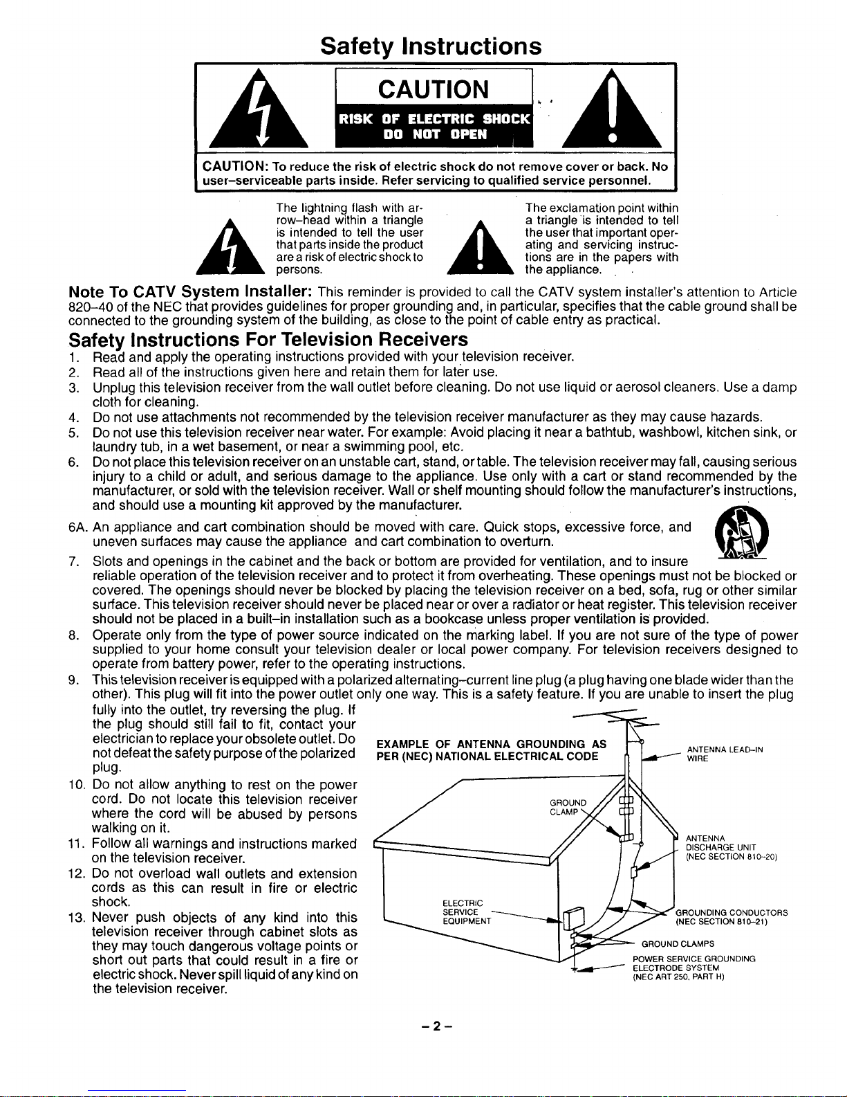
Note To CATV System Installer: This reminder is provided to call the CATV system installer's attention to Article
820-40 of the NEC that provides guidelines for proper grounding and, in particular, specifies that the cable ground shall be
connected to the grounding system of the building, as close to the point of cable entry as practical.
Safety Instructions For Television Receivers
1. Read and apply the operating instructions provided with your television receiver.
2. Read all of the instructions given here and retain them for later use.
3. Unplug this television receiver from the wall outlet before cleaning. Do not use liquid or aerosol cleaners. Use a clamp
cloth for cleaning.
4. Do not use attachments not recommended by the television receiver manufacturer as they may cause hazards.
5. Do not use this television receiver near water. For example: Avoid placing it near a bathtub, washbowl, kitchen sink, or
laundry tub, in a wet basement, or near a swimming pool, etc.
6. Do not place this television receiver on an unstable cart, stand, or table. The television receiver may fall, causing serious
injury to a child or adult, and serious damage to the appliance. Use only with a cart or stand recommended by the
manufacturer, or sold with the television receiver. Wall or shelf mounting should follow the manufacturer's instructions,
and should use a mounting kit approved by the manufacturer.
7. Slots and openings in the cabinet and the back or bottom are provided for ventilation, and to insure
reliable operation of the television receiver and to protect it from overheating. These openings must not be blocked or
covered. The openings should never be blocked by placing the television receiver on a bed, sofa, rug or other similar
surface. This television receiver should never be placed near or over a radiator or heat register. This television receiver
should not be placed in a built-in installation such as a bookcase unless proper ventilation iSprovided.
8. Operate only from the type of power source indicated on the marking label. If you are not sure of the type of power
supplied to your home consult your television dealer or local power company. For television receivers designed to
operate from battery power, refer to the operating instructions.
9. This television receiver isequipped with a polarized alternating-current line plug (a plug having one blade wider than the
other). This plug will fit into the power outlet only one way. This is a safety feature. If you are unable to insert the plug
6A. An appliance and cart combination should be moved with care. Quick stops, excessive force, and
uneven surfaces may cause the appliance and cart combination to overturn.
EXAMPLE OF ANTENNA GROUNDING AS i_
PER (NEC) NATIONAL ELECTRICAL C'()DF:'-_ ANTENNALEAD-IN
J GROUND // _ I_X
// "_..U._ p ANTENNA
, / J _" J,. DISCHARGE UNIT
I ELECTRIC / _ |
I SERVICE _ = _ ,/"'_/_'-,_ G ROUNDING CONDUCTORS
_...__PMENT _'_i_ _ (NEe SECTION 810-21)
_ GROUND CLAMPS
_ POWER SERVICE GROUNDING
_.,=_1"_'_" ELECTRODE SYSTEM
(NEC ART 250, PART H)
fully into the outlet, try reversing the plug. If
the plug should still fail to fit, contact your
electrician to replace your obsolete outlet. Do
not defeat the safety purpose of the polarized
plug.
10. Do not allow anything to rest on the power
cord. Do not locate this television receiver
where the cord will be abused by persons
walking on it.
11. Follow all warnings and instructions marked
on the television receiver.
12. Do not overload wall outlets and extension
cords as this can result in fire or electric
shock.
13. Never push objects of any kind into this
television receiver through cabinet slots as
they may touch dangerous voltage points or
short out parts that could result in a fire or
electric shock. Never spill liquid of any kind on
the television receiver.
-2-
14.I!anoutsideantennaisconnectedtothetelevisionequipment,besuretheantennasystemisgroundedsoastoprovide
someprotectionagainstvoltagesurgesandbuiltupstaticcharges.IntheU.S.Section810oftheNationalElectricalCode
andinCanadaPart1oftheCanadianElectricalCodeprovidesinformationwithrespecttopropergroundingofthemast
andsupportingstructure,groundingofthelead-inwiretoanantennadischargeunit,sizeofgroundingconductors,
locationofantenna-dischargeunit,connectiontogroundingelectrodes,andrequirementsforthegroundingelectrode.
SeeFigure.
15.Foraddedprotectionforthistelevisionreceiverduringalightningstorm,orwhenitisleftunattendedandunusedforlong
periodsoftime,unplugitfromthewalloutletanddisconnecttheantenna.Thiswillpreventdamagetothereceiverdueto
lightningandpower-linesurges.
16.Anoutsideantennasystemshouldnotbelocatedinthevicinityofoverheadpowerlinesorotherelectriclightorpower
circuits,orwhereitcanfallintosuchpowerlinesorcircuits.Wheninstallinganoutsideantennasystemextremecare
shouldbetakentokeepfromtouchingsuchpowerlinesorcircuitsascontactwiththemmightbefatal.
17.Unplugthistelevisionreceiverfromthewalloutlet,andreferservicingtoqualifiedservicepersonnelunderthefollowing
conditions:
a. Whenthepowercordorplugisdamagedorfrayed.
b. Ifliquidhasbeenspilledintothetelevisionreceiver.
c. tfthetelevisionreceiverhasbeenexposedtorainorwater.
d. Ifthetelevisionreceiverdoesnotoperatenormallybyfollowingtheoperatinginstructions.Adjustonlythosecontrols
thatarecoveredbytheoperatinginstructionsasimproperadjustmentofothercontrolsmayresultindamageandwill
oftenrequireextensiveworkbyaqualifiedtechniciantorestorethetelevisionreceivertonormaloperation.
e. Ifthetelevisionreceiverhasbeendroppedorthecabinethasbeendamaged.
f. Whenthetelevisionreceiverexhibitsadistinctchangeinperformance- thisindicatesaneedforservice.
18.Donotattempttoservicethistelevisionreceiveryourselfasopeningorremovingcoversmayexposeyoutodangerous
voltageorotherhazards.Referallservicingtoqualifiedservicepersonnel.
19.Whenreplacementpartsarerequired,besuretheservicetechnicianhasusedreplacementpartsspecifiedbythe
manufacturerthathavethesamecharacteristicsastheoriginalpart.Unauthorizedsubstitutionsmayresultinfire,electric
shock,orotherhazards.
20.Uponcompletionofanyserviceorrepairstothistelevisionreceiver,asktheservicetechniciantoperformroutinesafety
checkstodeterminethatthetelevisionis insafeoperatingcondition.
21.WARNING: To prevent fire or shock hazard, do not expose this appliance to rain or moisture.
22. CAUTION: TO PREVENT ELECTRIC SHOCK DO NOT USE THIS (POLARIZED) PLUG WITH AN EXTENSION CORD,
RECEPTACLE OR OTHER OUTLET UNLESS THE BLADES CAN BE FULLY INSERTED TO PREVENT BLADE
EXPOSURE.
NOTE: This equipment is designed to operate inthe U.S.A., Canada and other countries where the broadcasting system and
AC house current is exactly the same as in the U.S.A. and Canada.
Important Information Regarding Use of Video Games, Computers, Teletext or Other Fixed Image Displays.
The extended use of fixed image program material can cause a permanent "shadow image" on the picture tube. This
background image is viewable on normal programs in the form of a stationary fixed image. This type of irreversible picture tube
deterioration can be limited by observing the following steps:
A. Reduce the brightness/contrast setting to a minimum viewing level.
B. Do not display the fixed image for extended periods of time.
C. Turn the power off when not in actual use.
NOTE: The marking or retained image on the picture tube resulting from fixed image use is not an operating defect and as
such is not covered by Warranty. This product is not designed to display fixed image patterns for extended periods of
time.
Power Source:
Channel Capability:
Video Input Jack:
Audio Input Jacks:
To Audio AMP Jacks:
Stereo Sound
Closed Caption Display
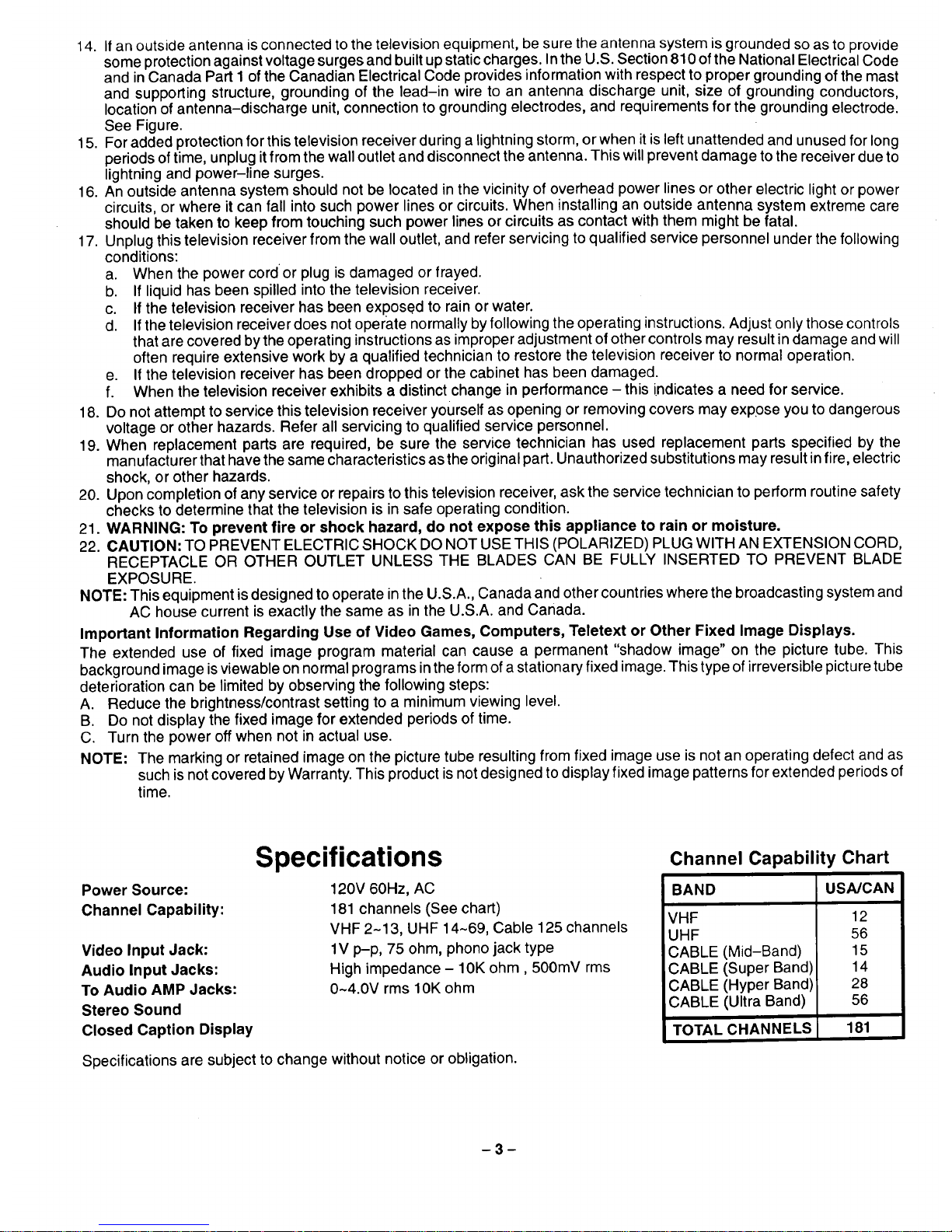
Specifications
120V 60Hz, AC
181 channels (See chart)
VHF 2-13, UHF 14-69, Cable 125 channels
1V p-p, 75 ohm, phono jack type
High impedance - 10K ohm, 500mV rms
0~4.0V rms 10K ohm
Specifications are subject to change without notice or obligation.
Channel Capability Chart
BAND USAJCAN
VHF 12
UHF 56
CABLE (Mid-Band) 15
CABLE (Super Band) 14
CABLE (Hyper Band) 28
CABLE (Ultra Band) 56
TOTAL CHANNELS 181
-3-
Introduction
Congratulations on Your New Purchase
Your new video component features an all solid state chassis which is designed to give you many years of enjoyment. It
was thoroughly tested and adjusted at the factory for best performance.
In order for you to take full advantage of your new video component, please read and follow the installation and operating
instructions supplied with this product.
Customer's Record
The model and serial number of this product may be found on itsback cover. You should note the model and serial number
in the space provided and retain this book as a permanent record of your purchase to aid in identification inthe event of
theft or loss.
Model Number:
Serial Number:
Table of Contents
Safety Instructions ............................. 2
Specifications ................................. 3
Introduction ................................... 4
Installation .................................... 5
Receiver Location .............................. 5
Optional External Equipment Connections ........ 5
AC Power Supply Cord ......................... 5
Battery Installation ............................. 5
Antenna/Cable Connections ..................... 6
Location of Controls ........................... 7
Quick Reference Control Operation .............. 7
Control Operation .............................. 8
Power Button .................................. 8
Volume (Vol) Buttons ........................... 8
Mute Button ................................... 8
Channel Change Features ...................... 8
Channel (Ch) Buttons ........................ 8
Keyboard "0 through 9" Buttons ............... 8
TV/Video Button ............................... 8
Recall Button .................................. 9
R-Tune (Rapid Tune) Button .................... 9
Skip Button ................................... 9
Main Menu (Icons) ............................ 10
Picture Adjustments ........................... 11
Color ...................................... 11
Tint ....................................... 11
Brightness ................................. 11
Picture .................................... 11
Sharpness ................................. 11
Picture Norm ............................... 11
Game Guard .................................. 12
Game Guard (Lockout) ...................... 12
Game Guard (Unlock) ....................... 13
Timer Features ................................ 14
Sleep Timer ................................ 14
Program Timer ............................. 15
Set-Up Features ............................. 16
Menu ..................................... 16
CC (Closed Caption) On Mute ................ 17
Set Time (Clock) ............................ 18
Antenna Tuning Mode ....................... 19
Auto Programming .......................... 20
Manual Programming ....................... 21
Closed Caption Mode ....................... 22
Channel Caption (Station Identifier) ............. 23
Audio Mode Selection ......................... 24
Audio Mode Selection (Stereo/SAP/Mono) .... 24
Video Input .................................. 25
Optional Equipment Connection & Operation ... 26
Stereo Connection (To Audio AMP) ............. 26
Video/Audio Connection ....................... 26
Care & Cleaning ............................... 27
Troubleshooting Chart ........................ 28
Power Loss .................................. 28

Installation
Location
Locate for comfortable viewing. Avoid placing where sunlight or other bright light (including reflections) will fall on the
scFeen.
Adequate ventilation is essential to prevent internal component failure. Keep away from areas of excessive heat or
moisture. Do not position magnetic equipment (motors, fans, other speakers, etc.) nearby.
Optional External Equipment Connections
The Video/Audio connections between components can be made with shielded video and audio cables. For best perfor-
mance, video cables should utilize 75 ohm coaxial shielded wire. Cables are available from your dealer or electronic
supply house.
Before you purchase any cables, be sure you know what type of output and input connectors your various components
require. Also determine the length of cable you'll need.
AC Power Supply Cord
Insert (Polarized) plug into 120 volts 60Hz standard AC outlet. Do not defeat the safety
purpose of the polarized plug.
CAUTION: TO PREVENT ELECTRIC SHOCK DO NOT USE THIS (POLARIZED) PLUG
WITH AN EXTENSION CORD, RECEPTACLE OR OTHER OUTLET UNLESS THE BLADE
CAN BE FULLY INSERTED TO PREVENT BLADE EXPOSURE.
Polarized Plug
Remote Control Battery Installation & Replacement
Battery Installation
Batteries: Use two "AA" batteries.
1. Turn the Transmitter face down. To remove bottom cover, press down on
marking and slide cover off in the direction indicated.
2. Install the batteries as shown inthe battery compartment. (Polarity (+) or
(-) must be correct.)
3. Replace the cover and slide in reverse until the lock snaps.
Precaution on Battery Use
Incorrect installation can cause battery leakage and corrosion that will
damage the Remote Control Transmitter.
Observe the Following Precautions:
1. Batteries must be replaced as a pair.
2. Do not combine a used battery with a new one.
3. Do not mix battery types (Example: "Zinc Carbon" with"Alkaline").
4. Do not attempt tocharge, short-circuit, disassemble, heat, or burn used
batteries.
5. Battery replacement is necessary when Remote Control reacts
sporadically or stops operating the Receiver.
m
I -=i=p-
®
o
®
®
®
Press Down Here And
Slide Cover Back
J
-5-

Antenna/Cable Connections
Antenna Connection - For proper reception of VHF/UHF channels an external
antenna is required. For best reception an outdoor antenna is recommended.
Antenna Mode must be set to TV. (Refer to Antenna Mode section.)
Incoming Cable From Home Antenna (75 Ohm)
VHF/UHF
on Back of Set
Indoor Outdoor
Typical VHF/UHF Antenna
Incoming Cable From Home Antenna (300 Ohm)
VHF/UHF
on Back of Set
300 to 75 ohm Matching
Transformer (Not Included)
Cable Connection- For reception ofcable channels (01~125) connect the cable supplied by your local cable company.
Antenna Mode must be set to CABLE. (Refer to Antenna Mode section.)
Incoming 75 Ohm Cable (From Cable Company)
VHF/UHF
on Back of Set
NOTE: Certain cable systems offset some channels to reduce interference or have Premium (scrambled) channels. A
cable converter box is required for proper reception. Check with your local Cable company for its compatibility
requirements.
Other Video Equipment
VCRs, Video Disc Players, Computers, TV games and Teletext equipment can also be connected to the antenna input
connection.
Location_of Controls_-', T_
Front Control Panel (In Some Models) _ I
t / I POWER MU
Remote Control
Sensor
©
®
®
PowE ii.IIvo..II,cHIIcH'II'cT°NIITvNOEOII
_ || ,_1 ,, ,_, " _ 'l _ ,,Rem_eeContro I
®
®
®
®
@
@
®
@
@
®
Quick Reference Control Operation
ACTION
R_)_ L SKIP
1 2 3
© © ©
4 5 6
© © ©
7 8 9
© © ©
®
®
®
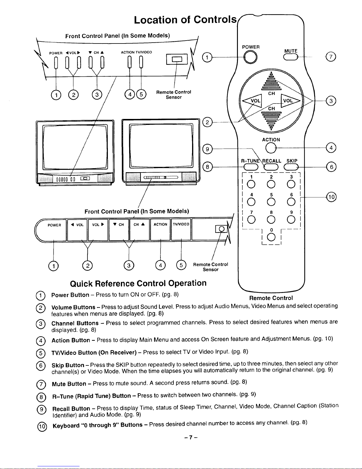
Power Button - Press to turn ON or OFF. (pg. 8)
Remote Control
Volume Buttons - Press to adjust Sound Level. Press to adjust Audio Menus, Video Menus and select operating
features when menus are displayed. (pg. 8)
Channel Buttons - Press to select programmed channels. Press to select desired features when menus are
displayed. (pg. 8)
Action Button - Press to display Main Menu and access On Screen feature and Adjustment Menus. (pg. 10)
TV/Video Button (On Receiver) - Press to select TV or Video Input. (pg. 8)
Skip Button - Press the SKIP button repeatedly to select desired time, upto three minutes, then select any other
channel(s) or Video Mode. When the time elapses you will automatically return to the original channel. (pg. 9)
Mute Button - Press to mute sound. A second press returns sound. (pg. 8)
R-Tune (Rapid Tune) Button - Press to switch between two channels. (pg. 9)
Recall Button - Press to display Time, status of Sleep Timer, Channel, Video Mode, Channel Caption (Station
Identifier) and Audio Mode. (pg. 9)
Keyboard "0 through 9" Buttons - Press desired channel number to access any channel. (pg. 8)
-7-
Control Operation
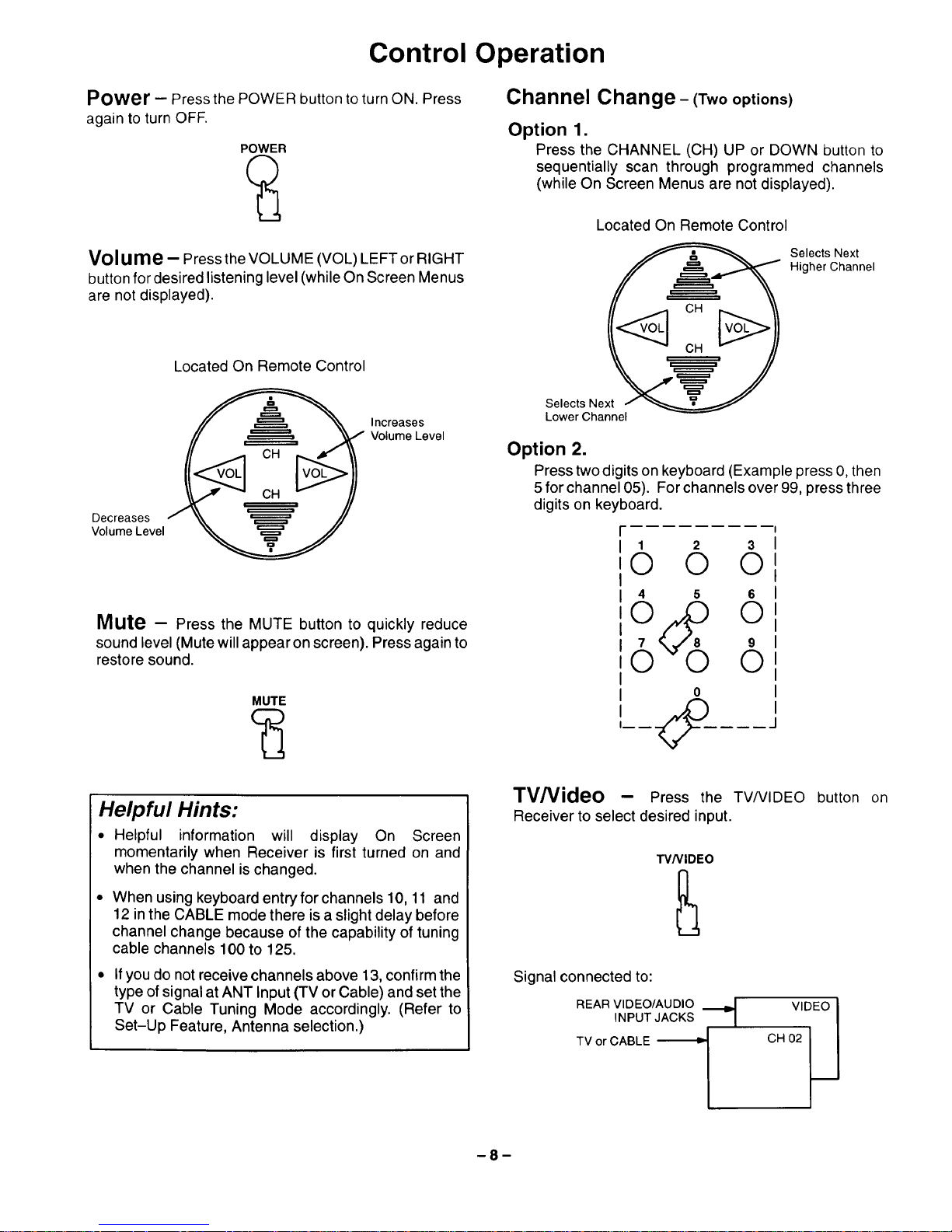
Power - Press the POWER button to turn ON. Press
again to turn OFF.
POWER
Volu me - Press the VOLUME (VOL) LEFT or RIGHT
button for desired listening level (while On Screen Menus
are not displayed).
Decreases
Volume Level
Located On Remote Control
Increases
Volume Level
Mute - Press the MUTE button to quickly reduce
sound level (Mute will appear on screen). Press again to
restore sound.
MUTE
Channel Change- (Twooptions)
Option 1.
Press the CHANNEL (CH) UP or DOWN button to
sequentially scan through programmed channels
(while On Screen Menus are not displayed).
Located On Remote Control
Selects Next
Higher Channel
Selects Ne
Lower Channel
Option 2.
Presstwo digits on keyboard (Example press 0, then
5 for channel 05). For channels over 99, press three
digits on keyboard.
1 2 3
© © ©
4 5 6
o
6 6
o
Helpful Hints:
• Helpful information will display On Screen
momentarily when Receiver is first turned on and
when the channel is changed.
When using keyboard entry for channels 10, 11 and
12 in the CABLE mode there is a slight delay before
channel change because of the capability of tuning
cable channels 100 to 125.
If you do not receive channels above 13, confirm the
type of signal at ANT Input (TV or Cable) and set the
TV or Cable Tuning Mode accordingly. (Refer to
Set-Up Feature, Antenna selection.)
TV/Video - Press the TV/VIDEO button on
Receiver to select desired input.
TV/VIDEO
Signal connected to:
REAR VIDEO/AUDIO ._
INPUT JACKS
TV or CABLE
VIDEO I
CH 02 _J
-8-
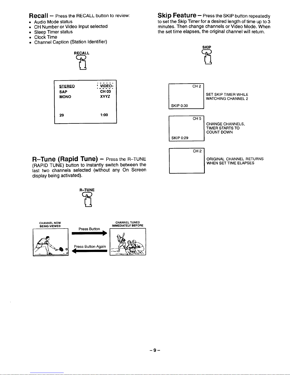
Recall - Press the RECALL button to review:
• Audio Mode status
• CH Number or Video Input selected
• Sleep Timer status
• Clock Time
• Channel Caption (Station Identifier)
RECALL
Skip Feature - Press the SKIP button repeatedly
to set the Skip Timer for a desired length of time up to 3
minutes. Then change channels or Video Mode. When
the set time elapses, the original channel will return.
SKIP
i .....
SAP CH 03
MONO XYYZ
29 1:00
CH 2
SKIP 0:30
CH 5
SKIP 0:29
CH 2
SET SKIP TIMER WHILE
WATCHING CHANNEL 2
CHANGE CHANNELS,
TIMER STARTS TO
COUNT DOWN
R-Tune (Rapid Tune) - PresstheR-TUNE
(RAPID TUNE) button to instantly switch between the
last two channels selected (without any On Screen
display being activated).
ORIGINAL CHANNEL RETURNS
WHEN SET TIME ELAPSES
R-TUNE
CHANNEL NOW
BEING VIEWED
CHANNEL TUNED
IMMEDIATELY BEFORE
ress Button Again
 Loading...