

Panasonic CT10R11S Operating Instructions Manual
Panasonic
Color Television
Operating Instructions
Read these instructions completely before operating this set.
Contents subject to change without notice or obligation.
Printed in U.S.A. TQB2A0817
Safety Instructions
CAUTION
CAUTION: To reduce the risk of electric shock do not remove cover cr back. No
user-serviceable parts inside. Refer servicing to qualified service personnel.
The lightning flash with ar-
_ row-head within a triangle _
is intended to tell the user
that parts inside the product
are a risk ofelectric shock to
persons.
The exclamation point within
a triangle is inlended to tell
the user that ircportant oper-
ating and servicing instruc-
tions are in the papers with
the appliance.
Note To CATV System Installer: This reminder is provided to call the CATV system installer's attention to Article
820-40 of the NEC that provides guidelines for proper grounding and, in particular, specifies that the caMe ground shall be
connected to the grounding system of the building, as close to the point of cable entry as practical.
Safety Instructions For Television Receivers
1. Read and apply the operating instructions provided with your television receiver.
2. Read all of the instructions given here and retain them for later use.
3. Unplug this television receiver from the wall outlet before cleaning. Do not use liquid or aerosol cleaners. Use a damp
cloth for cleaning.
4. Do not use attachments not recommended by the television receiver manufacturer as they may cause hazards.
5. Do not use this television receiver near water. For example: Avoid placing it near a bathtub, washbowl, kitchen sink, or
laundry tub, in a wet basement, or near a swimming pool, etc.
6. Do not place this television receiver on an unstable cart, stand, or table. The television r_=ceivermay fall, causing serious
injury 1:oa child or adult, and serious damage to the appliance. Use only with a carl or stand recommended by the
manufacturer, or sold with the television receiver. Wall or shelf mount ng should follow the manufacturer's instructions,
and should use a mounting kit approved by the manufacturer.
6A. An appliance and cart combination should be moved with care. Quick stops, excessive force, and
uneven surfaces may cause the appliance and cart combination to overturn.
7. Slots and openings in the cabinet and the back or bottom are provided for ventilation, and to insure:
reliable operation of the television receiver and to protect it from overheating. These openings must not be blocked or
covered. The openings should never be blocked by placing the television receiver on a bed, sofa, rug, or other similar
surface. This television receiver should never be placed near or over a radiator or heat register. This television receiver
should not be placed in a built-in installation such as a bookcase unless proper venti ation is provided.
8. Operate only from the type of power source indicated on the marking label. If you are not sure ol the type of power
supplied to your home consult your television dealer or local power company. For television receivers designed to
operate from battery power, refer to the operating instructions.
9. This television receiver is equipped with a polarized alternating--current line plug (a pluc having one blade wider than the
other). This plug will fit into the power outlet only one way.This is a safety feature. If you are unable to insert the plug
fully into the outlet, try reversing the plug. If
the plug should still fail to fit, contact your
electrician to replace your obsolete outlet. Do
not defeat the safety purpose of the polarized
plug.
10. Do not allow anything to rest on the power
cord. Do not locate this television receiver
where the cord will be abused by persons
walking on it.
11. Follow all warnings and instructions marked
on the,television receiver.
12. Do not overload wall outlets and extension
cords as this can result in fire or electric
shock.
13. Never push objects of any kind into this
television receiver through cabinet slots as
they may touch dangerous voltage points or
short out parts that could result in a fire or
electric shock. Never spill liquid of any kind on
the television receiver.
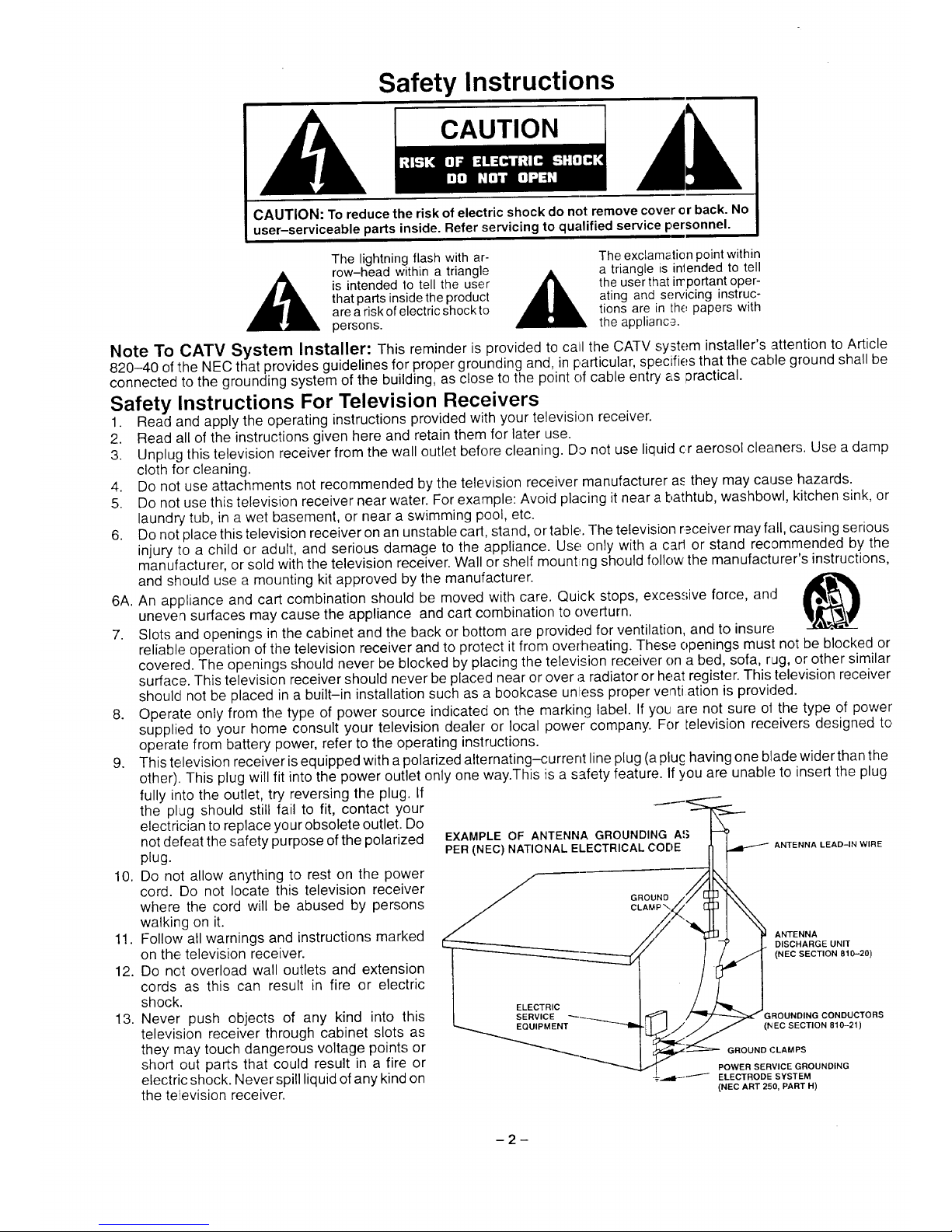
EXAMPLE OF ANTENNA GROUNDING AS
PER (NEC) NATIONAL ELECTRICAL CODE
ANTENNA LEAD-IN WIRE
ANTENNA
DISCHARGE UNIT
(NEC SECTION 810-20)
,_ROUNDING CONDUCTORS
(/'.lEO SECTION 810-21)
GROUND (.'LAMPS
POWER SERVICE GROUNDING
.-'.._dl_'"--'-"_ ELECTRODE SYSTEM
(NEC ART 250, PART H)
2
14. If an outside antenna is connected to the television equipment, be sure the antenna system is grounded so as to provide
some protection against voltage surges and built up static charges. In the U.S. Section 8"!0 ofthe National Electrical Code
and in Canada Part 1 of the Canadian Electrical Code provides information with respect to proper grounding of the mast
and supporting structure, grounding of the lead-in wire to an antenna discharge unit, .size of grounding conductors,
location of antenna-discharge unit, connection to grounding electrodes, and requiremenls for the grounding electrode.
See Figure.
15. For added protection for this television receiver during a lightning storm, er when it is left unattended ancl unused for long
periods of time, unplug it from the wall outlet and disconnect the antenna. -I-hiswill prevent damage to the receiver due to
lightning and power-line surges.
16. An outside antenna system should not be located in the vicinity of overhead power lines 3r other electric light or power
circuits, or where it can fall into such power lines or circuits. When installing an outside antenna system extreme care
should be,taken to keep from touching such power lines or circuits as contact with them might be fatal.
17. Unplug this television receiver from the wall outlet, and refer servicing to qualified service personnel under the following
conditions:
a. When the power cord or plug is damaged or frayed.
b. If liquid has been spilled into the television receiver.
c. Ifthe television receiver has been exposed to rain or water.
d. Ifthe television receiver does not operate normally by following the operating instructions. Adjust only those controls
that are covered by the operating instructions as improper adjustment of other controls may result in damage and will
often require extensive work by a qualified technician to restore the television receiver to normal operation.
e. If the television receiver has been dropped or the cabinet has been damaged.
f. When the television receiver exhibits a distinct change in performance - this indicates a need for service.
18. Do not attempt to service this television receiver yourself as opening or removing covers may expose you to dangerous
voltage or other hazards. Refer all servicing to qualified service personrel.
19. When replacement parts are required, be sure the service technician has used replacement parts specified by the
manufacturer that have the same characteristics as the original part. Unabthorized substitutions may result in fire, electric
shock, or other hazards.
20. Upon completion of any service or repairs to this television receiver, ask the service technician to perform routine safety
checks to determine that the television is in safe operating condition.
21. WARNING: To prevent fire or shock hazard, do not expose this appliance to rain o{" moisture.
2;_>. CAUTION: TO PREVENT ELECTRIC SHOCK DO NOT USE THIS (POLARIZED) PLUG WITH AN EXTENSION CORD,
RECEPTACLE OR OTHER OUTLET UNLESS THE BLADES CAN BE FULLY INSERTED TO PREVENT BLADE
EXPOSURE.
NOTE: This equipment is designed to operate in the U.S.A., Canada and other countries where the broadcasting system and
AC house current is exactly the same as in the U.S.A. and Canada.
Important Information Regarding Use of Video Games, Computers, Teletext or Other' Fixed Image r)isplays.
The extended use of fixed image program material can cause a permanent "shadow ima;le" on the picture tube. This
background image is viewable on normal programs in the form of a stationary fixed image. This type of irreversible picture tube
deterioration ('an be limited by observing the following steps:
A Reduce the brightness/contrast setting to a minimum viewing level.
B Do not display the fixed image for extended periods of time.
C. Turn the power off when not in actual use.
NOTE: The marking or retained image on the picture tube resulting from fixed image use is rot an operating defect and as
such is not covered by Warranty. This product is not designed to display fixed image patterns for extended periods of
time.
Power Source:
Cl_annel Capability:
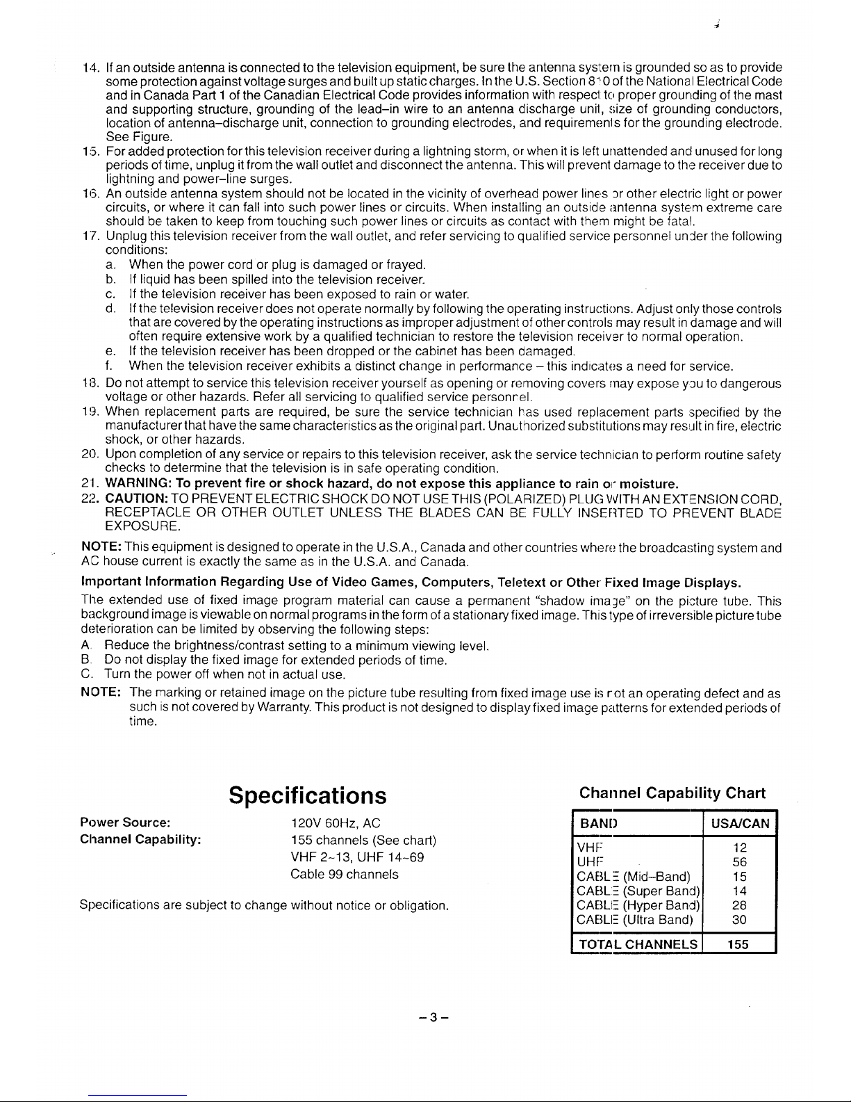
Specifications
120V 60Hz, AC
155 channels (See chart)
VHF 2-13, UHF 14-69
Cable 99 channels
Specifications are subject to change without notice or obligation.
Channel Capability Chart
BAN[) USA/CAN
VHF
UHF
CABLE (Mid-Band)
CABL:E (Super Band)
CABLIE (Hyper Band)
CABLE (Ultra Band)
12
56
15
14
28
30
TOTAL CHANNELS 155
Introduction
Congratulations on Your New Purchase
Your new video component features an all solid state chassis which is designed to give you many year.,; of enjoyment. It
was thoroughly tested and adjusted at the factory for best performance.
Inorder for you to take full advantage of your new video component, please read and follow the installation and operating
instructions supplied with this product.
Customer's Record
The model and serial number of this product may be found on its back cower. You should note the model and serial number
in the space provided and retain this book as a permanent record of your purchase to aid in identification in the event of
theft or loss.
Model Number:
Serial Number:
Table of Contents
Safety Instructions ............................. 2
Specifications ................................. 3
Introduction ................................... 4
Installation .................................... 4
Antenna Connection ........................... 5
Battery Installation ............................. 5
Location of Controls ........................... 6
Quick Reference Control Operation .............. 6
Control Operation .............................. 7
Power Button .................................. 7
Vol (Votume) Buttons ........................... 7
Level (+) & (-) Buttons ......................... 7
Ch (Channel) Buttons .......................... 7
Set Up Button ................................. 7
Auto Channel Programming ................... 8
Add/Erase Channels ......................... 8
Tuning System Antenna/Cable ................ 8
Set (;lock ................................... 8
Video Button .................................. 9
Color ........................................ 9
Tint ......................................... 9
Brightness .................................. 9
Picture ..................................... 9
Sharpness .................................. 9
Norm (Normalize) Button ....................... 9
R-Tune (Rapid Tune) B Jtton .................... 9
On Timer Button ............................... 10
Sleep Button ................................. 11
Recall Button ................................. 11
Channel Keyboard "0 through 9" Buttons ......... 11
Mute Button .................................. 11
Skip Button ................................... 11
Menu Button .................................. 12
Earphone Jack ................................ 12
Care & Cleaning ............................... 13
Troubleshooting Chart ........................ 14
Installation
Location
Locate for comfortable viewing. Avoid placing where sunlight or other bright light (inclJding reflection,';) will fall on the
screen.
Adequate ventilation is essential to prevent internal component failure. Keep away from areas of excessive heat or
moisture. Do not position magnetic equipment (motors, fans, other speakers, etc.) nearby.
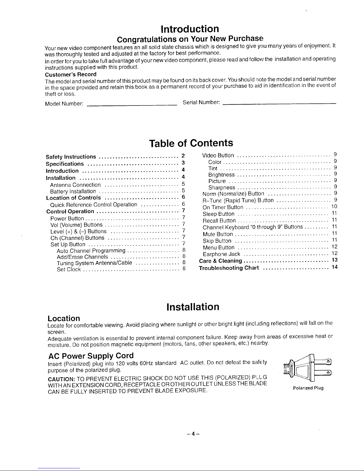
AC Power Supply Cord
Insert (Polarized) plug into 120 volts 60Hz standard AC outlet, Do not defeat the safety
purpose of the polarized plug.
CAUTION: TO PREVENT ELECTRIC SHOCK DO NOT USE THIS (POLARIZED) PI_LG
WITH AN EXTENSION CORD, RECEPTACLE OR OTHER OUTLET UNLESS THE BLADE
CAN BE FULLY INSERTED TO PREVENT BLADE EXPOSURE.
Polarized Plug
-4-
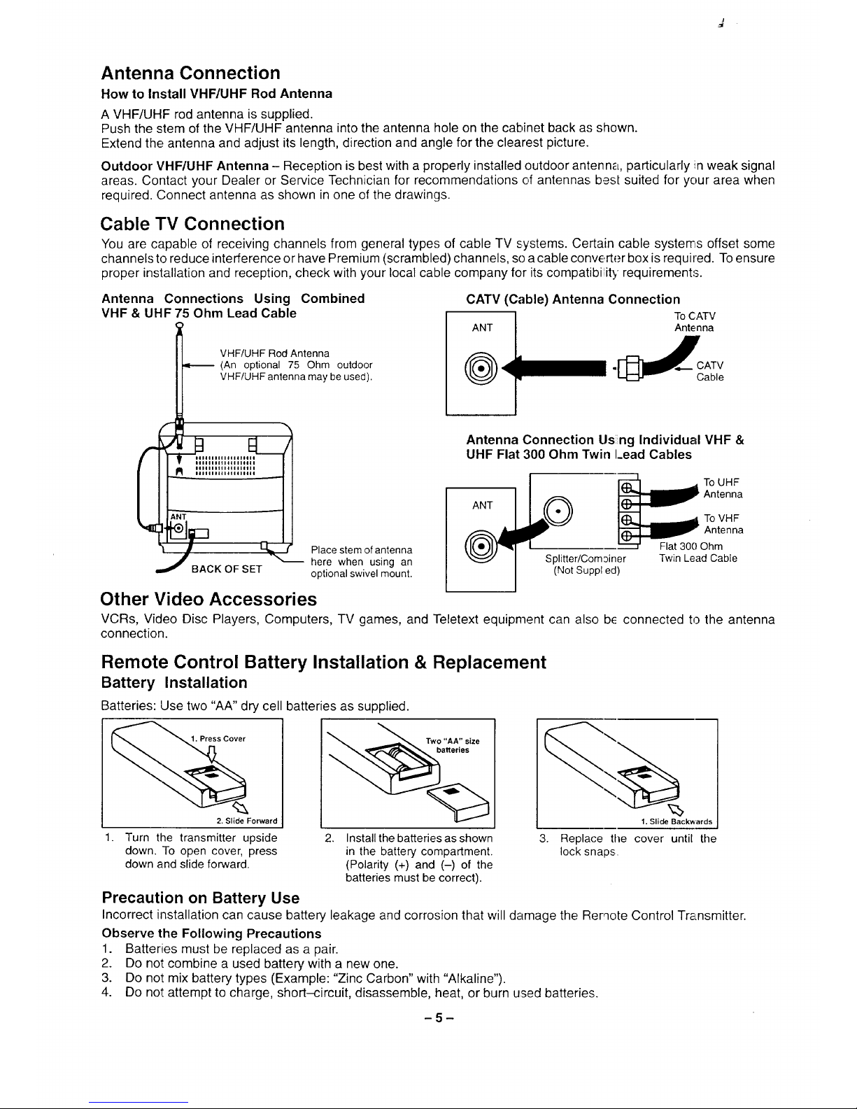
Antenna Connection
How to Install VHF/UHF Rod Antenna
A VHF/UHF rod antenna is supplied.
Push the stem of the VHF/UHF antenna into the antenna hole on the cabinet back as shown.
Extend the antenna and adjust its length, direction and angle for the clearest picture.
Outdoor VHF/UHF Antenna - Reception is best with a properly installed outdoor antenna, particularly in weak signal
areas. Contact your Dealer or Service Technician for recommendations of antennas bes[ suited for your area when
required. Connect antenna as shown in one of the drawings.
Cable TV Connection
You are capable of receiving channels from general types of cable TV systems. Certain cable systems offset some
channels to reduce interference or have Premium (scrambled) channels, so a cable converter box is required. To ensure
proper installation and reception, check with your local cable company for its compatibi',ity requirements.
Antenna Connections Using Combined
VHF & UHF 75 Ohm Lead Cable
VHF/UHF Rod Antenna
_-_ (An optional 75 Ohm outdoor
VHF/UHF antenna may be used).
_llllllllllllll_
J BACK OF SET
Place stem of antenna
here when using an
optional swivel mount.
CATV (Cable) Antenna Connection
To C:ATV
ANT Antenna
CATV
Cable
Antenna Connection Using Individual VHF &
UHF Flat 300 Ohm Twin I_ead Cables
Splitter/Comoiner
(Not Suppled)
Twin Lead Cable
Other Video Accessories
VCRs, Video Disc Players, Computers, TV games, and Teletext equipment can also b_ connected to the antenna
connection.
Remote Control Battery Installation & Replacement
Battery Installation
Batteries: Use two "AA" dry cell batteries as supplied.
1. Press Cover
2. Slide Forward
_Two "AA" size
___,_a_eries
Turn the transmitter upside
down. To open cover, press
down and slide forward.
%
1. Slide Backwards
2. Install the batteries as shown 3. Replace the cover until the
in the battery compartment, lock snaps.
(Polarity (+) and (-) of the
batteries must be correct).
Precaution on Battery Use
Incorrect installation can cause battery leakage and corrosion that will damage the Remote Control Transmitter.
Observe the Following Precautions
1. Batteries must be replaced as a pair.
2. Do not combine a used battery with a new one.
3. Do not mix battery types (Example: "Zinc Carbon" with "Alkaline").
4. Do not attempt to charge, short-circuit, disassemble, heat, or burn used batteries.
-5-
 Loading...