

Page 1
© Panasonic Corporation 2012.
Order No: PAPAMY1211001CE
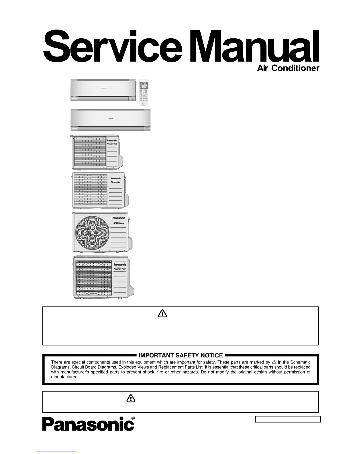
Indoor Unit Outdoor Unit
CS-S10PKH
CS-S13PKH
CS-S15PKH
CS-S18PKH
CS-S24PKH
CU-S10PKH
CU-S13PKH
CU-S15PKH
CU-S18PKH
CU-S24PKH
Destination
Malaysia
Myanmar
S.E.Asia
PRECAUTION OF LOW TEMPERATURE
In order to avoid frostbite, be assured of no refrigerant leakage during the installation or repairing of refrigerant circuit.
WARNING
This service information is designed for experienced repair technicians only and is not designed for use by the general public.
It does not contain warnings or cautions to advise non-technical individuals of potential dangers in attempting to service a product.
Products powered by electricity should be serviced or repaired only by experienced professional technicians. Any attempt to
service or repair the products dealt with in this service information by anyone else could result in serious injury or death.
Page 2

2
TABLE OF CONTENTS
1. Safety Precautions .............................................3
2. Specification .......................................................5
3. Location of Controls and Components..........21
3.1 Indoor Unit ..................................................21
3.2 Outdoor Unit ...............................................21
3.3 Remote Control ..........................................21
4. Dimensions .......................................................22
4.1 Indoor Unit ..................................................22
4.2 Outdoor Unit ...............................................24
5. Refrigeration Cycle Diagram ...........................27
5.1 CS-S10PK CU-S10PK
CS-S13PK CU-S13PK
CS-S15PK CU-S15PK................................27
5.2 CS-S18PK CU-S18PK
CS-S24PK CU-S24PK................................28
6. Block Diagram ..................................................29
6.1 CS-S10PKH CU-S10PKH (Malaysia only).29
6.2 CS-S10PK CU-S10PK (expect Malaysia) ..30
6.3 CS-S13PK CU-S13PK ...............................31
6.4 CS-S15PK CU-S15PK ...............................32
6.5 CS-S18PK CU-S18PK ...............................33
6.6 CS-S24PK CU-S24PK ...............................34
7. Wiring Connection Diagram ............................35
7.1 Indoor Unit ..................................................35
7.2 Outdoor Unit ...............................................37
8. Electronic Circuit Diagram ..............................42
8.1 Indoor Unit ..................................................42
8.2 Outdoor Unit ...............................................44
9. Printed Circuit Board .......................................48
9.1 Indoor Unit ..................................................48
9.2 Outdoor Unit ...............................................52
10. Installation Instruction.....................................57
10.1 Select The Best Location ...........................57
10.2 Indoor Unit ..................................................58
10.3 Outdoor Unit ...............................................63
11. Installation Instruction.....................................66
11.1 Select The Best Location ...........................66
11.2 Indoor Unit ..................................................67
11.3 Outdoor Unit ...............................................72
12. Operation Control.............................................75
12.1 Basic Function ............................................75
12.2 Indoor Fan Motor Operation .......................76
12.3 Outdoor Fan Motor Operation
(For S10/13/15/18PK).................................76
12.4 Outdoor Fan Motor Operation (For S24PK) ...
....................................................................76
12.5 Airflow Direction..........................................77
12.6 Quiet Operation (Cooling Mode/Cooling Area
of Dry Mode)...............................................78
12.7 Powerful Mode Operation...........................78
12.8 Timer Control..............................................79
12.9 Random Auto Restart Control ................... 79
12.10 Indication Panel ......................................... 79
12.11 nanoe-G Operation .................................... 80
12.12 In-filter Deactivation Operation .................. 82
12.13 Mild Dry Cooling Operation ....................... 83
12.14 AUTO COMFORT and ECONAVI Operation .
................................................................... 83
13. Protection Control........................................... 93
13.1 Restart Control (Time Delay Safety Control)..
................................................................... 93
13.2 30 Seconds Forced Operation .................. 93
13.3 Total Running Current Control .................. 93
13.4 IPM (Power Transistor) Prevention Control93
13.5 Compressor Overheating Prevention Control
(For S18, S24PK only)............................... 94
13.6 Low Pressure Prevention Control (Gas
Leakage Detection) ................................... 94
13.7 Compressor Tank Temperature Rise
Protection Control...................................... 94
13.8 Low Frequency Protection Control 1 ......... 94
13.9 Low Frequency Protection Control 2 ......... 94
13.10 Outdoor Air Temperature Control .............. 95
13.11 Cooling Overload Control .......................... 95
13.12 Freeze Prevention Control 1 ..................... 95
13.13 Freeze Prevention Control 2 ..................... 95
13.14 Dew Prevention Control ............................ 95
13.15 Odor Cut Control ....................................... 96
14. Servicing Mode................................................ 97
14.1 Auto Off/On Button .................................... 97
14.2 Remote Control Button.............................. 98
15. Troubleshooting Guide................................... 99
15.1 Refrigeration Cycle System....................... 99
15.2 Breakdown Self Diagnosis Function........ 101
15.3 Error Code Table ..................................... 102
15.4 Troubleshooting Flowchart ...................... 103
16. Disassembly and Assembly Instructions ... 129
16.1 CS-S10PK CS-S13PK CS-S15PK ........ 129
16.2 CS-S18PK CS-S24PK............................ 133
17. Technical Data ............................................... 137
17.1 Operation Characteristics........................ 137
18. Exploded View and Replacement Parts List157
18.1 Indoor Unit ............................................... 157
18.2 Outdoor Unit ............................................ 171
Page 3
3
1. Safety Precautions
• Read the following “SAFETY PRECAUTIONS” carefully before perform any servicing.
• Electrical work must be installed or serviced by a licensed electrician. Be sure to use the correct rating of the power plug and
main circuit for the model installed.
• The caution items stated here must be followed because these important contents are related to safety. The meaning of each
indication used is as below. Incorrect installation or servicing due to ignoring of the instruction will cause harm or damage,
and the seriousness is classified by the following indications.
WARNING
This indication shows the possibility of causing death or serious injury.
CAUTION
This indication shows the possibility of causing injury or damage to properties.
• The items to be followed are classified by the symbols:
This symbol denotes item that is PROHIBITED from doing.
• Carry out test run to confirm that no abnormality occurs after the servicing. Then, explain to user the operation, care and
maintenance as stated in instructions. Please remind the customer to keep the operating instructions for future reference.
WARNING
1. Do not modify the machine, part, material during repairing service.
2. If wiring unit is supplied as repairing part, do not repair or connect the wire even only partial wire break. Exchange the whole wiring unit.
3. Do not wrench the fasten terminal. Pull it out or insert it straightly.
4.
Engage authorized dealer or specialist for installation and servicing. If installation of servicing done by the user is defective, it will cause
water leakage, electrical shock or fire.
5. Install according to this installation instructions strictly. If installation is defective, it will cause water leakage, electric shock or fire.
6.
Use the attached accessories parts and specified parts for installation and servicing. Otherwise, it will cause the set to fall, water leakage,
fire or electrical shock.
7.
Install at a strong and firm location which is able to withstand the set’s weight. If the strength is not enough or installation is not properly
done, the set will drop and cause injury.
8.
For electrical work, follow the local national wiring standard, regulation and the installation instruction. An independent circuit and single
outlet must be used. If electrical circuit capacity is not enough or defect found in electrical work, it will cause electrical shock or fire.
9.
This equipment is strongly recommended to be installed with Earth Leakage Circuit Breaker (ELCB) or Residual Current Device (RCD).
Otherwise, it may cause electrical shock and fire in case equipment breakdown or insulation breakdown.
10.
Do not use joint cable for indoor/outdoor connection cable. Use the specified indoor/outdoor connection cable, refer to installation
instruction CONNECT THE CABLE TO THE INDOOR UNIT and connect tightly for indoor/outdoor connection. Clamp the cable so that no
external force will be acted on the terminal. If connecting or fixing is not perfect, it will cause heat up or fire at the connection.
11.
Wire routing must be properly arranged so that control board cover is fixed properly. If control board cover is not fixed perfectly, it will
cause heat-up or fire at the connection point of terminal, fire or electrical shock.
12.
When install or relocate air conditioner, do not let any substance other than the specified refrigerant, eg. air etc. mix into refrigeration cycle
(piping). (Mixing of air etc. will cause abnormal high pressure in refrigeration cycle and result in explosion, injury etc.).
13.
Do not install outdoor unit near handrail of veranda. When installing air-conditioner unit at veranda of high rise building, child may climb up
to outdoor unit and cross over the handrail and causing accident.
14.
This equipment must be properly earthed. Earth line must not be connected to gas pipe, water pipe, earth of lightning rod and
telephone. Otherwise, it may cause electrical shock in case equipment breakdown or insulation breakdown.
15. Keep away from small children, the thin film may cling to nose and mouth and prevent breathing.
16.
Do not use unspecified cord, modified cord, joint cord or extension cord for power supply cord. Do not share the single outlet with
other electrical appliances. Poor contact, poor insulation or over current will cause electrical shock or fire.
17.
Tighten the flare nut with torque wrench according to specified method. If the flare nut is over-tightened, after a long period, the flare may
break and cause refrigerant gas leakage.
18.
For R410A model, use piping, fl are nut and tools which is specified for R410A refrigerant. Using of existing (R22) piping, fl are
nut and tools may cause abnormally high pressure in the refrigerant cycle (piping), and possibly result in explosion and injury.
Thickness of copper pipes used with R410A must be more than 0.6mm. Never use copper pipes thinner than 0.6mm.
It is desirable that the amount of residual oil is less than 40 mg/10m.
Page 4
4
WARNING
19.
During installation, install the refrigerant piping properly before run the compressor. (Operation of compressor without fixing refrigeration
piping and valves at opened condition will cause suck-in of air, abnormal high pressure in refrigeration cycle and result in explosion, injury
etc.).
20.
During pump down operation, stop the compressor before remove the refrigeration piping. (Removal of refrigeration piping while
compressor is operating and valves are opened condition will cause suck-in of air, abnormal high pressure in refrigeration cycle and result
in explosion, injury etc.) .
21.
After completion of installation or service, confirm there is no leakage of refrigerant gas. It may generate toxic gas when the refrigerant
contacts with fire.
22. Ventilate if there is refrigerant gas leakage during operation. It may cause toxic gas when the refrigerant contacts with fire.
23. Do not insert your fingers or other objects into the unit, high speed rotating fan may cause injury
24. Must not use other parts except original parts describe in catalog and manual.
25. Using of refrigerant other than the specified type may cause product damage, burst and injury etc.
CAUTION
1.
Do not install the unit at place where leakage of flammable gas may occur. In case gas leaks and accumulates at surrounding of
the unit, it may cause fire.
2.
Carry out drainage piping as mentioned in installation instructions. If drainage is not perfect, water may enter the room and damage the
furniture.
3.
Tighten the flare nut with torque wrench according to specified method. If the flare nut is over-tightened, after a long period, the flare may
break and cause refrigerant gas leakage.
4. Do not touch outdoor unit air inlet and aluminium fin. It may cause injury.
5. Select an installation location which is easy for maintenance.
6.
Pb free solder has a higher melting point than standard solder; typically the melting point is 50°F – 70°F (30°C – 40°C) higher. Please use
a high temperature solder iron. In case of the soldering iron with temperature control, please set it to 700 ± 20°F (370 ± 10°C).
Pb free solder will tend to splash when heated too high (about 1100°F / 600°C).
7.
CS/CU-S10/13/15/18/24PK
Power supply connection to the room air conditioner.
Use power supply cord 3 × 1.5 mm² (1.0 ~ 1.75HP) or 3 × 2.5 mm² (2.0 ~ 2.5HP) type designation 60245 IEC 57 or heavier cord. Connect
the power supply cord of the air conditioner to the mains using one of the following method. Power supply point should be in easily
accessible place for power disconnection in case of emergency. In some countries, permanent connection of this air conditioner to the
power supply is prohibited.
i. Power supply connection to the receptacle using power plug.
Use an approved 15/16A (1.0 ~ 1.75HP) or 16A (2.0HP) or 20A (2.5HP) power plug with earth pin for the connection to the socket.
ii. Power supply connection to a circuit breaker for the permanent connection.
Use an approved 16A (1.0 ~ 2.0HP) or 20A (2.5HP) circuit breaker for the permanent connection. It must be a double pole switch with
a minimum 3.0 mm contact gap.
8.
Myanmar only
Power supply connection to the room air conditioner.
Use power supply cord 3 × 1.5 mm² (1.0 ~ 1.5HP) or 3 × 2.5 mm² (2.0 ~ 2.5HP) type designation 60245 IEC 57 or heavier cord. Connect
the power supply cord of the air conditioner to the mains using one of the following method. Power supply point should be in easily
accessible place for power disconnection in case of emergency. In some countries, permanent connection of this air conditioner to the
power supply is prohibited.
i. Power supply connection to the receptacle using power plug.
Use an approved 15/16A (1.0 ~ 1.5HP) or 16A (2.0HP) or 20A (2.5HP) power plug with earth pin for the connection to the socket.
ii. Power supply connection to a circuit breaker for the permanent connection.
Use an approved 16A (1.0 ~ 2.0HP) or 20A (2.5HP) circuit breaker for the permanent connection. It must be a double pole switch with
a minimum 3.0 mm contact gap.
9.
Do not release refrigerant during piping work for installation, servicing, reinstallation and during repairing a refrigerant parts. Take
care of the liquid refrigerant, it may cause frostbite.
10. Installation or servicing work: It may need two people to carry out the installation or servicing work.
11. Do not install this appliance in a laundry room or other location where water may drip from the ceiling, etc.
12. Do not sit or step on the unit, you may fall down accidentally.
13.
Do not touch the sharp aluminum fins or edges of metal parts.
If you are required to handle sharp parts during installation or servicing, please wear hand glove.
Sharp parts may cause injury.
Page 5
5
2. Specification
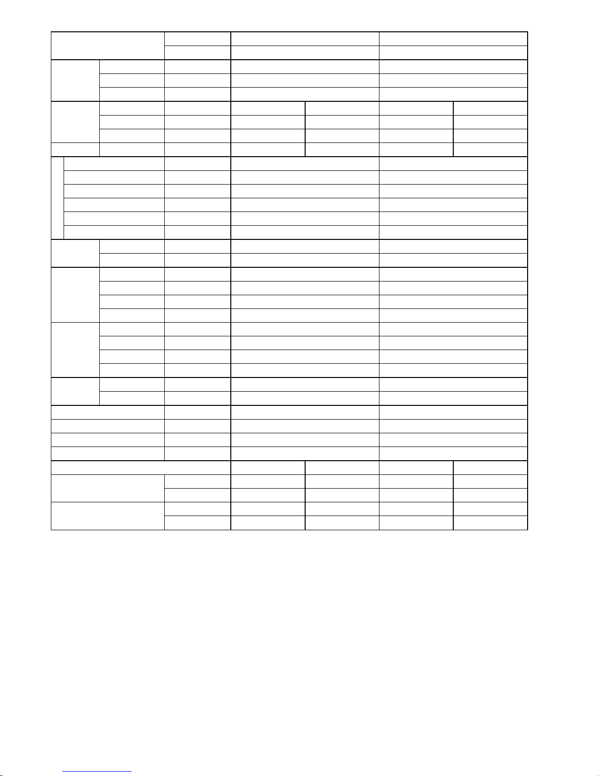
Indoor CS-S10PKH (MALAYSIA) CS-S13PKH (MALAYSIA)
Model
Outdoor CU-S10PKH (MALAYSIA) CU-S13PKH (MALAYSIA)
Performance Test Condition JIS JIS
Phase, Hz Single, 50 Single, 50
Power Supply
V 230 230
Min. Mid. Max. Min. Mid. Max.
kW 0.84 2.80 3.28 0.92 3.66 4.20
BTU/h 2860 9550 11200 3140 12500 14300
Capacity
kJ/h 3020 10080 11810 3310 13180 15120
Running Current A – 3.6 – – 4.8 –
Input Power W 225 760 920 260 1.04k 1.20k
W/W 3.73 3.68 3.57 3.54 3.52 3.50
BTU/hW 12.71 12.57 12.17 12.08 12.02 11.92
EER
kJ/hW 13.42 13.26 12.84 12.73 12.67 12.60
Power Factor % – 92 – – 94 –
Indoor Noise (H / L / QLo) dB-A 36 / 26 / 23 38 / 28 / 25
Cooling
Outdoor Noise (H / L / QLo) dB-A 47 / – / – 48 / – / –
Max Current (A) / Max Input Power (W) 5.6 / 1.12k 7.4 / 1.40k
Starting Current (A) 3.6 4.8
Type Hermetic Motor / Rotary Hermetic Motor / Rotary
Motor Type Brushless (6 poles) Brushless (6 poles)
Compressor
Output Power W 500 650
Type Cross-Flow Fan Cross-Flow Fan
Material ASG20K1 ASG20K1
Motor Type DC / Transistor (8-poles) AC / Induction (4 poles)
Input Power W 47.3 54.5
Output Power W 40 24
QLo rpm 610 650
Lo rpm 680 720
Me rpm 840 910
Hi rpm 1000 1100
Indoor Fan
Speed
SHi rpm 1130 1130
Type Propeller Fan Propeller Fan
Material PP Resin PP Resin
Motor Type AC / Induction (6 poles) AC / Induction (6 poles)
Input Power W – –
Output Power W 30 25
Outdoor Fan
Speed Hi rpm 790 810
Moisture Removal L/h (Pt/h) 1.6 (3.4) 2.1 (4.4)
QLo m3/min (ft3/min) 5.5 (194) 5.6 (198)
Lo m3/min (ft3/min) 6.4 (226) 6.4 (251)
Me m3/min (ft3/min) 8.3 (293) 8.7 (307)
Hi m3/min (ft3/min) 10.1 (355) 10.9 (385)
Indoor Airflow
SHi m
3
/min (ft3/min) 11.7 (413) 11.3 (399)
Outdoor
Airflow
Hi m
3
/min (ft3/min) 22.4 (790) 31.9 (1130)
Page 6
6
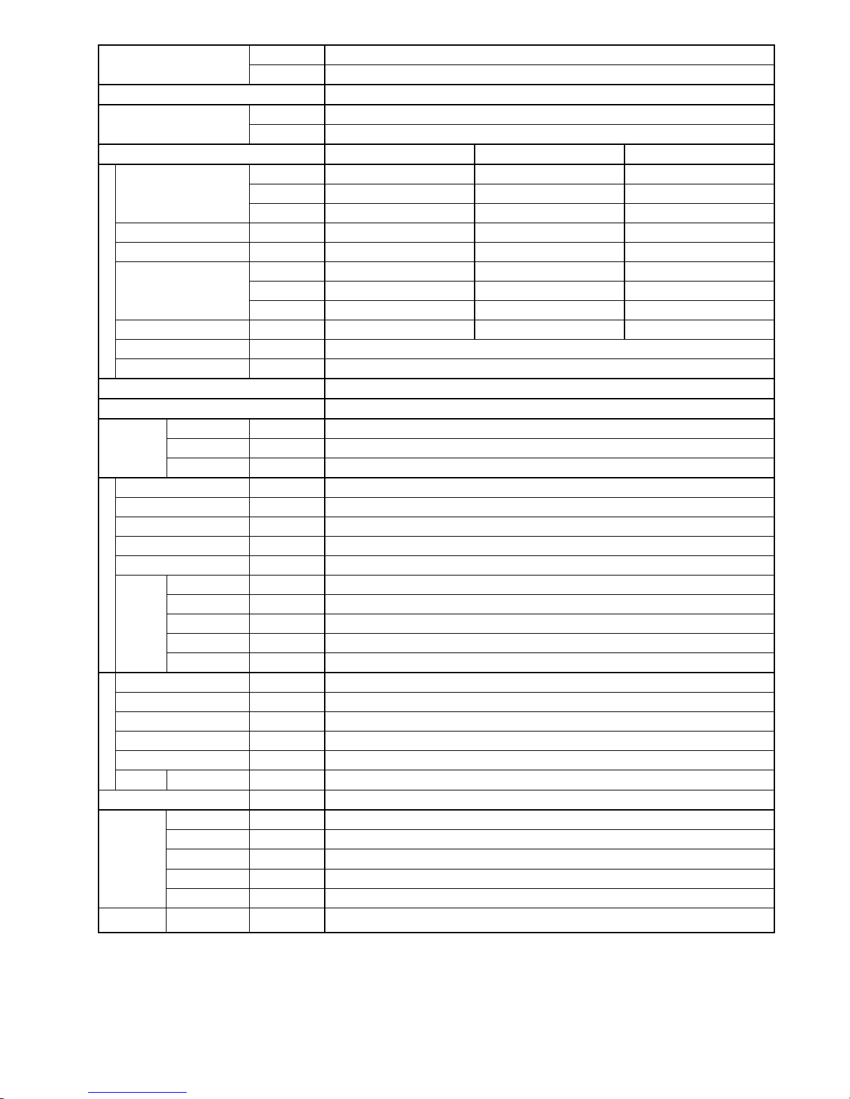
Indoor CS-S10PKH (MALAYSIA) CS-S13PKH (MALAYSIA)
Model
Outdoor CU-S10PKH (MALAYSIA) CU-S13PKH (MALAYSIA)
Control Device Capillary Tube Capillary Tube
Refrigerant Oil cm3 FV50S (250) FV50S (320)
Refrigeration
Cycle
Refrigerant Type g (oz) R410A, 740 (26.1) R410A, 690 (24.4)
Height (I/D / O/D) mm (inch) 290 (11-7/16) 511 (20-1/8) 290 (11-7/16) 542 (21-11/32)
Width (I/D / O/D) mm (inch) 870 (34-9/32) 650 (25-19/32) 870 (34-9/32) 780 (30-23/32)
Dimension
Depth (I/D / O/D) mm (inch) 214 (8-7/16) 230 (9-1/16) 214 (8-7/16) 289 (11-13/32)
Weight Net (I/D / O/D) kg (lb) 9 (20) 20 (44) 9 (20) 30 (66)
Pipe Diameter (Liquid / Gas) mm (inch) 6.35 (1/4) / 9.52 (3/8) 6.35 (1/4) / 12.70 (1/2)
Standard length m (ft) 7.5 (24.6) 7.5 (24.6)
Length range (min – max) m (ft) 3 (9.8) ~ 15 (49.2) 3 (9.8) ~ 15 (49.2)
I/D & O/D Height different m (ft) 5 (16.4) 5 (16.4)
Additional Gas Amount g/m (oz/ft) 15 (0.2) 15 (0.2)
Piping
Length for Additional Gas m (ft) 7.5 (24.6) 7.5 (24.6)
Inner Diameter mm 16.7 16.7
Drain Hose
Length mm 550 550
Fin Material Aluminium (Pre Coated) Aluminium (Pre Coated)
Fin Type Slit Fin Slit Fin
Row × Stage × FPI 2 × 15 × 17 2 × 15 × 17
Indoor Heat
Exchanger
Size (W × H × L) mm 610 × 315 × 25.4 610 × 315 × 25.4
Fin Material Aluminium (Blue Coated) Aluminium (Blue Coated)
Fin Type Slit Fin Louver Fin
Row × Stage × FPI 1.5 × 23 × 17 1 × 20 × 19
Outdoor Heat
Exchanger
Size (W × H × L) mm 25.4 × 483.0 × 553.4:573.4 22.0 × 508.0 × 708.4
Material Polypropelene Polypropelene
Air Filter
Type One-touch One-touch
Power Supply Indoor Indoor
Power Supply Cord A 10 10
Thermostat – –
Protection Device – –
DRY BULB WET BULB DRY BULB WET BULB
Maximum °C 32 23 32 23
Indoor Operation Range
Minimum °C 16 11 16 11
Maximum °C 43 26 43 26
Outdoor Operation Range
Minimum °C 16 11 16 11
1. Cooling capacities are based on indoor temperature of 27°C DRY BULB (80.6°F DRY BULB), 19.0°C WET BULB (66°F WET BULB) and
outdoor air temperature of 35°C DRY BULB (95°F DRY BULB), 24°C WET BULB (75.2°F WET BULB)
Page 7
7
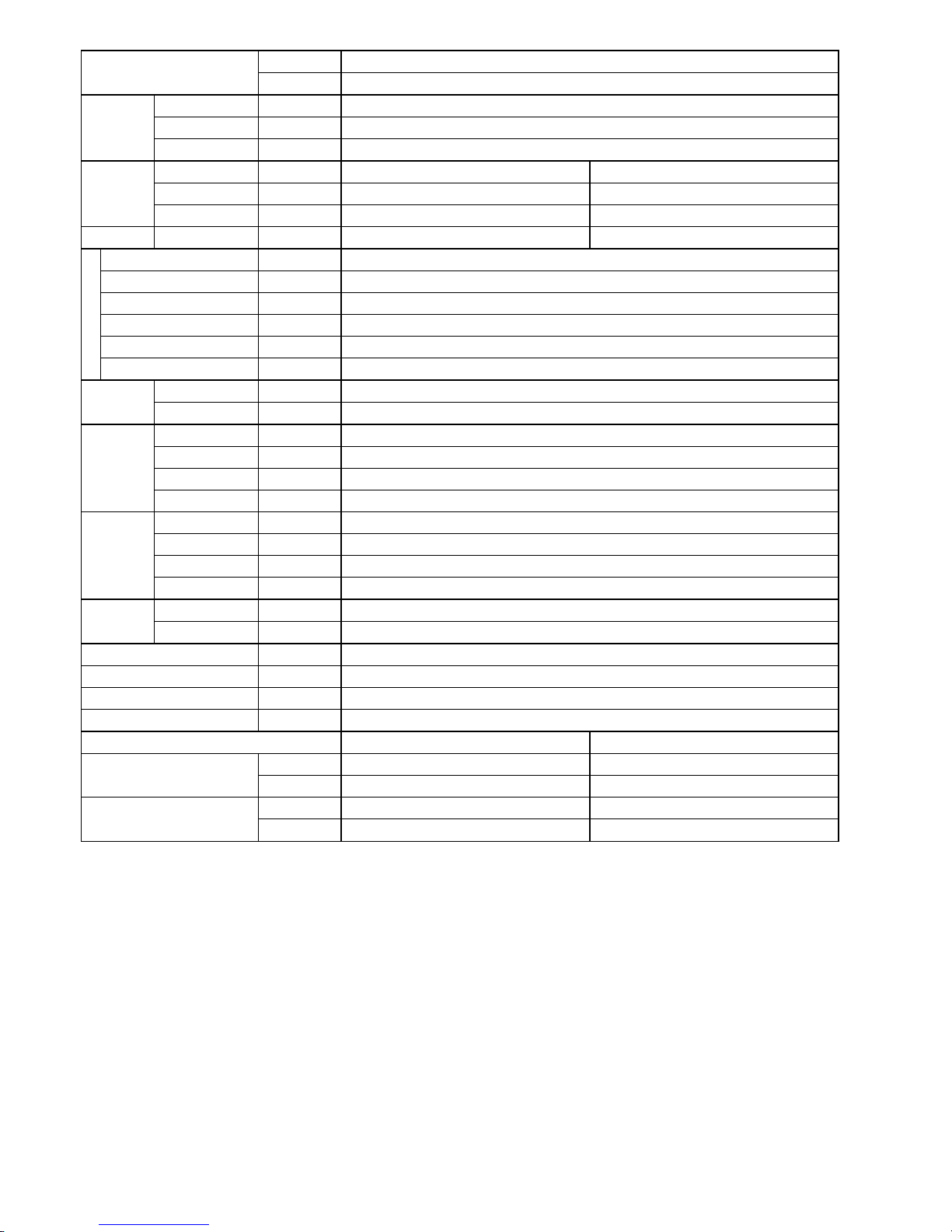
Indoor CS-S15PKH (MALAYSIA)
Model
Outdoor CU-S15PKH (MALAYSIA)
Performance Test Condition JIS
Phase, Hz Single, 50
Power Supply
V 230
Min. Mid. Max.
kW 1.07 4.40 5.00
BTU/h 3650 15000 17100
Capacity
kJ/h 3850 15840 18000
Running Current A – 5.4 –
Input Power W 285 1.18k 1.36k
W/W 3.75 3.73 3.68
BTU/hW 12.81 12.71 12.57
EER
kJ/hW 13.51 13.42 13.24
Power Factor % – 95 –
Indoor Noise (H / L / QLo) dB-A 43 / 30 / 27
Cooling
Outdoor Noise (H / L / QLo dB-A 50 / – / –
Max Current (A) / Max Input Power (W) 8.3 / 1.74k
Starting Current (A) 5.4
Type Hermetic Motor / Rotary
Motor Type Brushless (6 poles)
Compressor
Output Power W 700
Type Cross-Flow Fan
Material ASG20K1
Motor Type DC / Transistor (8-poles)
Input Power W 47.3
Output Power W 40
QLo rpm 710
Lo rpm 780
Me rpm 1010
Hi rpm 1240
Indoor Fan
Speed
SHi rpm 1340
Type Propeller Fan
Material PP Resin
Motor Type AC / Induction (6 poles)
Input Power W –
Output Power W 30
Outdoor Fan
Speed Hi rpm 830
Moisture Removal L/h (Pt/h) 2.4 (5.1)
QLo m3/min (ft3/min) 6.6 (233)
Lo m3/min (ft3/min) 7.5 (265)
Me m3/min (ft3/min) 10.1 (357)
Hi m3/min (ft3/min) 12.8 (450)
Indoor Airflow
SHi m
3
/min (ft3/min) 14.0 (404)
Outdoor
Airflow
Hi m
3
/min (ft3/min) 31.0 (1090)
Page 8
8
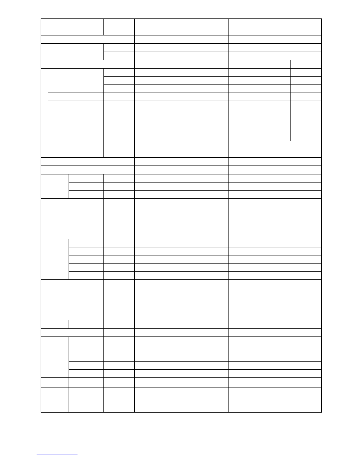
Indoor CS-S15PKH (MALAYSIA)
Model
Outdoor CU-S15PKH (MALAYSIA)
Control Device Capillary tube
Refrigerant Oil cm3 FV50S (320)
Refrigeration
Cycle
Refrigerant Type g (oz) R410A, 950 (33.5)
Height (I/D / O/D) mm (inch) 290 (11-7/16) 542 (21-11/32)
Width (I/D / O/D) mm (inch) 870 (34-9/32) 780 (30-23/32)
Dimension
Depth (I/D / O/D) mm (inch) 214 (8-7/16) 289 (11-13/32)
Weight Net (I/D / O/D) kg (lb) 9 (20) 31 (68)
Pipe Diameter (Liquid / Gas) mm (inch) 6.35 (1/4) / 12.70 (1/2)
Standard length m (ft) 7.5 (24.6)
Length range (min – max) m (ft) 3 (9.8) ~ 15 (49.2)
I/D & O/D Height different m (ft) 5 (16.4)
Additional Gas Amount g/m (oz/ft) 15 (0.2)
Piping
Length for Additional Gas m (ft) 7.5 (24.6)
Inner Diameter mm 16.7
Drain Hose
Length mm 550
Fin Material Aluminium (Pre coated)
Fin Type Slit Fin
Row × Stage × FPI 2 × 15 × 21
Indoor Heat
Exchanger
Size (W × H × L) mm 610 × 315 × 25.4
Fin Material Aluminium (Blue coated)
Fin Type Slit Fin
Row × Stage × FPI 2 × 23 × 17
Outdoor Heat
Exchanger
Size (W × H × L) mm 25.4 × 504.0 × 693.4:713.4
Material Polypropelene
Air Filter
Type One-touch
Power Supply Indoor
Power Supply Cord A 10
Thermostat –
Protection Device –
DRY BULB WET BULB
Maximum °C 32 23
Indoor Operation Range
Minimum °C 16 11
Maximum °C 43 26
Outdoor Operation Range
Minimum °C 16 11
1. Cooling capacities are based on indoor temperature of 27°C DRY BULB (80.6°F DRY BULB), 19.0°C WET BULB (66°F WET BULB) and
outdoor air temperature of 35°C DRY BULB (95°F DRY BULB), 24°C WET BULB (75.2°F WET BULB)
Page 9
9
Indoor CS-S18PKH (MALAYSIA) CS-S24PKH (MALAYSIA)
Model
Outdoor CU-S18PKH (MALAYSIA) CU-S24PKH (MALAYSIA)
Performance Test Condition JIS JIS
Phase, Hz Single, 50 Single, 50
Power Supply
V 230 230
Min. Mid. Max. Min. Mid. Max.
kW 1.10 5.27 6.00 1.12 6.25 7.10
BTU/h 3750 18000 20500 3820 21300 24200
Capacity
kJ/h 3960 18970 21600 4030 22500 25560
Running Current A – 6.8 – – 8.6 –
Input Power W 290 1.47k 1.70k 320 1.88k 2.20k
W/W 3.79 3.59 3.53 3.50 3.32 3.23
BTU/hW 12.93 12.24 12.06 11.94 11.33 11.00
EER
kJ/hW 13.66 12.90 12.71 12.59 11.97 11.62
Power Factor % – 94 – – 95 –
Indoor Noise (H / L / QLo) dB-A 44 / 32 / 29 45 / 34 / 31
Cooling
Outdoor Noise (H / L / QLo) dB-A 50 / – / – 52 / – / –
Max Current (A) / Max Input Power (W) 10.5 / 2.19k 11.7 / 2.35k
Starting Current (A) 6.8 8.6
Type Hermetic Motor / Rotary Hermetic Motor / Rotary
Motor Type Brushless (6 poles) Brushless (6 poles)
Compressor
Output Power W 900 900
Type Cross-Flow Fan Cross-Flow Fan
Material ASG30K1 ASG30K1
Motor Type DC / Transistor (8-poles) DC / Transistor (8-poles)
Input Power W 94.8 94.8
Output Power W 40 40
QLo rpm 750 850
Lo rpm 820 920
Me rpm 1040 1150
Hi rpm 1260 1370
Indoor Fan
Speed
SHi rpm 1400 1450
Type Propeller Fan Propeller Fan
Material PP Resin PP Resin
Motor Type AC / Induction (6 poles) AC / Induction (6 poles)
Input Power W – –
Output Power W 30 74
Outdoor Fan
Speed Hi rpm 910 820
Moisture Removal L/h (Pt/h) 2.9 (6.1) 3.5 (7.4)
QLo m3/min (ft3/min) 9.9 (350) 10.3 (364)
Lo m3/min (ft3/min) 11.0 (389) 11.4 (403)
Me m3/min (ft3/min) 14.4 (508) 14.6 (516)
Hi m3/min (ft3/min) 17.7 (625) 18.1 (640)
Indoor Airflow
SHi m
3
/min (ft3/min) 19.9 (703) 19.3 (682)
Outdoor
Airflow
Hi m
3
/min (ft3/min) 35.6 (1255) 45.8 (1615)
Control Device Capillary Tube Capillary Tube
Refrigerant Oil cm3 FV50S (450) FV50S (450)
Refrigeration
Cycle
Refrigerant Type g (oz) R410A, 1.09k (38.5) R410A, 1.29k (45.5)
Page 10
10
Indoor CS-S18PKH (MALAYSIA) CS-S24PKH (MALAYSIA)
Model
Outdoor CU-S18PKH (MALAYSIA) CU-S24PKH (MALAYSIA)
Height (I/D / O/D) mm (inch) 290 (11-7/16) 619 (24-3/8) 290 (11-7/16) 695 (27-3/8)
Width (I/D / O/D) mm (inch) 1070 (42-5/32) 824 (32-15/32) 1070 (42-5/32) 875 (34-15/32)
Dimension
Depth (I/D / O/D) mm (inch) 240 (9-15/32) 299 (11-25/32) 240 (9-15/32) 320 (12-5/8)
Weight Net (I/D / O/D) kg (lb) 12 (26) 32 (71) 12 (26) 44 (97)
Pipe Diameter (Liquid / Gas) mm (inch) 6.35 (1/4) / 12.70 (1/2 ) 6.35 (1/4) / 15.88 (5/8)
Standard length m (ft) 5.0 (16.4) 5.0 (16.4)
Length range (min – max) m (ft) 3 (9.8) ~ 20 (65.6) 3 (9.8) ~ 20 (65.6)
I/D & O/D Height different m (ft) 15 (49.2) 15 (49.2)
Additional Gas Amount g/m (oz/ft) 15 (0.2) 20 (0.2)
Piping
Length for Additional Gas m (ft) 10 (32.8) 10 (32.8)
Inner Diameter mm 16.7 16.7
Drain Hose
Length mm 550 550
Fin Material Aluminium (Pre Coated) Aluminium (Pre Coated)
Fin Type Slit Fin Slit Fin
Row × Stage × FPI 2 × 15 × 17 2 × 15 × 21
Indoor Heat
Exchanger
Size (W × H × L) mm 810 × 315 × 25.4 810 × 315 × 25.4
Fin Material Aluminium (Blue Coated) Aluminium (Blue Coated)
Fin Type Slit Fin Slit Fin
Row × Stage × FPI 1.5 × 16:28 × 17 2 × 31 × 17
Outdoor
Heat
Exchanger
Size (W × H × L) mm 25.4 × 336:588 × 775.4:795.3 25.4 × 651 × 640
Material Polypropelene Polypropelene
Air Filter
Type One-touch One-touch
Power Supply Indoor Indoor
Power Supply Cord A 15 20
Thermostat – –
Protection Device – –
DRY BULB WET BULB DRY BULB WET BULB
Maximum °C 32 23 32 23
Indoor Operation Range
Minimum °C 16 11 16 11
Maximum °C 43 26 43 26
Outdoor Operation Range
Minimum °C 16 11 16 11
1. Cooling capacities are based on indoor temperature of 27°C DRY BULB (80.6°F DRY BULB), 19.0°C WET BULB (66°F WET BULB) and
outdoor air temperature of 35°C DRY BULB (95°F DRY BULB), 24°C WET BULB (75.2°F WET BULB
Page 11
11
Indoor CS-S10PKH (MYANMAR) CS-S13PKH (MYANMAR)
Model
Outdoor CU-S10PKH (MYANMAR) CU-S13PKH (MYANMAR)
Performance Test Condition JIS JIS
Phase, Hz Single, 50 Single, 50
Power Supply
V 220 240 220 240
Min. Mid. Max. Min. Mid. Max. Min. Mid. Max. Min. Mid. Max.
kW 0.84 2.85 3.28 0.84 2.85 3.28 0.92 3.67 4.20 0.92 3.67 4.20
BTU/h 2860 9720 11200 2860 9720 11200 3140 12500 14300 3140 12500 14300
Capacity
kJ/h 3020 10260 11810 3020 10260 11810 3310 13210 15120 3310 13210 15120
Running Current A – 3.6 – – 3.3 – – 5.1 – – 4.6 –
Input Power W 225 730 920 225 730 920 260 1.01k 1.20k 260 1.01k 1.20k
W/W 3.73 3.90 3.57 3.73 3.90 3.57 3.54 3.63 3.50 3.54 3.63 3.50
BTU/hW 12.71 13.32 12.17 12.71 13.32 12.17 12.08 12.38 11.92 12.08 12.38 11.92
EER
kJ/hW 13.42 14.05 12.84 13.42 14.05 12.84 12.73 13.08 12.60 12.73 13.08 12.60
Power Factor % – 92 – – 92 – – 90 – – 91 –
Indoor Noise (H / L / QLo) dB-A 36 / 26 / 23 36 / 26 / 23 38 / 28 / 25 38 / 28 / 25
Cooling
Outdoor Noise (H / L / QLo) dB-A 46 / – / – 47 / – / – 47 / – / – 48 / – / –
Max Current (A) / Max Input Power (W) 5.6 / 1.12k 7.4 / 1.40k
Starting Current (A) 3.6 5.1
Type Hermetic Motor / Rotary Hermetic Motor / Rotary
Motor Type Brushless (6 poles) Brushless (6 poles)
Compressor
Output Power W 500 650
Type Cross-Flow Fan Cross-Flow Fan
Material ASG20K1 ASG20K1
Motor Type AC / Induction (4 poles) AC / Induction (4 poles)
Input Power W 51.0 - 58.0 51.0 - 58.0
Output Power W 24 24
QLo rpm 610 - 610 650 - 650
Lo rpm 680 - 680 720 - 720
Me rpm 840 - 840 910 - 910
Hi rpm 1000 - 1000 1100 - 1100
Indoor Fan
Speed
SHi rpm 1130 - 1130 1130 - 1130
Type Propeller Fan Propeller Fan
Material PP Resin PP Resin
Motor Type AC / Induction (6 poles) AC / Induction (6 poles)
Input Power W – –
Output Power W 30 25
Outdoor Fan
Speed Hi rpm 770 - 800 790 - 820
Moisture Removal L/h (Pt/h) 1.7 (3.6) 2.1 (4.4)
QLo m3/min (ft3/min) 5.5 (194) 5.6 (198)
Lo m3/min (ft3/min) 6.4 (226) 6.4 (251)
Me m3/min (ft3/min) 8.3 (293) 8.7 (307)
Hi m3/min (ft3/min) 10.1 (355) 10.9 (385)
Indoor
Airflow
SHi m
3
/min (ft3/min) 11.7 (413) 11.3 (399)
Outdoor
Airflow
Hi m
3
/min (ft3/min) 22.0 (780) 22.9 (810) 31.2 (1100) 32.6 (1150)
Page 12
12
Indoor CS-S10PKH (MYANMAR) CS-S13PKH (MYANMAR)
Model
Outdoor CU-S10PKH (MYANMAR) CU-S13PKH (MYANMAR)
Control Device Capillary Tube Capillary Tube
Refrigerant Oil cm3 FV50S (250) FV50S (320)
Refrigeration
Cycle
Refrigerant Type g (oz) R410A, 740 (26.1) R410A, 690 (24.4)
Height (I/D / O/D) mm (inch) 290 (11-7/16) 511 (20-1/8) 290 (11-7/16) 542 (21-11/32)
Width (I/D / O/D) mm (inch) 870 (34-9/32) 650 (25-19/32) 870 (34-9/32) 780 (30-23/32)
Dimension
Depth (I/D / O/D) mm (inch) 214 (8-7/16) 230 (9-1/16) 214 (8-7/16) 289 (11-13/32)
Weight Net (I/D / O/D) kg (lb) 9 (20) 20 (44) 9 (20) 30 (66)
Pipe Diameter (Liquid / Gas) mm (inch) 6.35 (1/4) / 9.52 (3/8) 6.35 (1/4) / 12.70 (1/2)
Standard length m (ft) 7.5 (24.6) 7.5 (24.6)
Length range (min – max) m (ft) 3 (9.8) ~ 15 (49.2) 3 (9.8) ~ 15 (49.2)
I/D & O/D Height different m (ft) 5 (16.4) 5 (16.4)
Additional Gas Amount g/m (oz/ft) 15 (0.2) 15 (0.2)
Piping
Length for Additional Gas m (ft) 7.5 (24.6) 7.5 (24.6)
Inner Diameter mm 16.7 16.7
Drain Hose
Length mm 550 550
Fin Material Aluminium (Pre coated) Aluminium (Pre coated)
Fin Type Slit Fin Slit Fin
Row × Stage × FPI 2 × 15 × 17 2 × 15 × 17
Indoor Heat
Exchanger
Size (W × H × L) mm 610 × 315 × 25.4 610 × 315 × 25.4
Fin Material Aluminium (Blue coated) Aluminium (Blue coated)
Fin Type Slit Fin Louver Fin
Row × Stage × FPI 1.5 × 23 × 17 1 × 20 × 19
Outdoor
Heat
Exchanger
Size (W × H × L) mm 25.4 × 483.0 × 553.4:573.4 22.0 × 508.0 × 708.4
Material Polypropelene Polypropelene
Air Filter
Type One-touch One-touch
Power Supply Indoor Indoor
Power Supply Cord A 10 10
Thermostat – –
Protection Device – –
DRY BULB WET BULB DRY BULB WET BULB
Maximum °C 32 23 32 23
Indoor Operation Range
Minimum °C 16 11 16 11
Maximum °C 43 26 43 26
Outdoor Operation Range
Minimum °C 16 11 16 11
1. Cooling capacities are based on indoor temperature of 27°C DRY BULB (80.6°F DRY BULB), 19.0°C WET BULB (66°F WET BULB) and
outdoor air temperature of 35°C DRY BULB (95°F DRY BULB), 24°C WET BULB (75.2°F WET BULB)
Page 13
13
Indoor CS-S18PKH (MYANMAR) CS-S24PKH (MYANMAR)
Model
Outdoor CU-S18PKH (MYANMAR) CU-S24PKH (MYANMAR)
Performance Test Condition JIS JIS
Phase, Hz Single, 50 Single, 50
Power Supply
V 220 240 220 240
Min. Mid. Max. Min. Mid. Max. Min. Mid. Max. Min. Mid. Max.
kW 1.10 5.30 6.00 1.10 5.30 6.00 1.12 6.25 7.10 1.12 6.25 7.10
BTU/h 3750 18100 20500 3750 18100 20500 3820 21300 24200 3820 21300 24200
Capacity
kJ/h 3960 19080 21600 3960 19080 21600 4030 22500 25560 4030 22500 25560
Running Current A – 7.0 – – 6.4 – – 8.8 – – 8.2 –
Input Power W 290 1.44k 1.70k 290 1.44k 1.70k 320 1.88k 2.20k 320 1.88k 2.20k
W/W 3.79 3.68 3.53 3.79 3.68 3.53 3.50 3.32 3.23 3.50 3.32 3.23
BTU/hW 12.93 12.57 12.06 12.93 12.57 12.06 11.94 11.33 11.00 11.94 11.33 11.00
EER
kJ/hW 13.66 13.25 12.71 13.66 13.25 12.71 12.59 11.97 11.62 12.59 11.97 11.62
Power Factor % – 94 – – 94 – – 97 – – 96 –
Indoor Noise (H / L / QLo) dB-A 44 / 32 / 29 44 / 32 / 29 45 / 34 / 31 45 / 34 / 31
Cooling
Outdoor Noise (H / L / QLo) dB-A 49 / – / – 50 / – / – 51 / – / – 52 / – / –
Max Current (A) / Max Input Power (W) 10.5 / 2.19k 11.7 / 2.35k
Starting Current (A) 7.0 8.8
Type Hermetic Motor / Rotary Hermetic Motor / Rotary
Motor Type Brushless (6 poles) Brushless (6 poles)
Compressor
Output Power W 900 900
Type Cross-Flow Fan Cross-Flow Fan
Material ASG30K1 ASG30K1
Motor Type DC / Transistor (8-poles) DC / Transistor (8-poles)
Input Power W 94.8 - 94.8 94.8 - 94.8
Output Power W 40 40
QLo rpm 750 - 750 850 - 850
Lo rpm 820 - 820 920 - 920
Me rpm 1040 - 1040 1150 - 1150
Hi rpm 1260 - 1260 1370 - 1370
Indoor Fan
Speed
SHi rpm 1400 - 1400 1450 - 1450
Type Propeller Fan Propeller Fan
Material PP Resin PP Resin
Motor Type AC / Induction (6-poles) AC / Induction (6-poles)
Input Power W – –
Output Power W 30 74
Me rpm – –
Outdoor Fan
Speed
Hi rpm 900 - 930 810 - 840
Moisture Removal L/h (Pt/h) 2.9 (6.1) 3.5 (7.4)
QLo m3/min (ft3/min) 9.9 (350) 10.3 (364)
Lo m3/min (ft3/min) 11.0 (389) 11.4 (403)
Me m3/min (ft3/min) 14.4 (508) 14.6 (516)
Hi m3/min (ft3/min) 17.7 (625) 18.1 (640)
Indoor Airflow
SHi m
3
/min (ft3/min) 19.9 (703) 19.3 (682)
Outdoor Airflow Hi m3/min (ft3/min) 35.0 (1235) 36.2 (1280) 45.0 (1590) 46.6 (1645)
Page 14
14
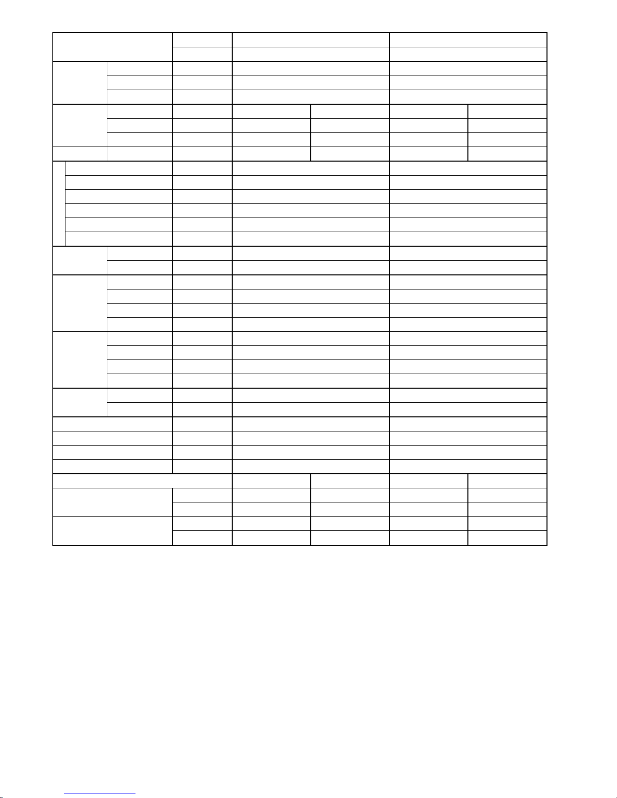
Indoor CS-S18PKH (MYANMAR) CS-S24PKH (MYANMAR)
Model
Outdoor CU-S18PKH (MYANMAR) CU-S24PKH (MYANMAR)
Control Device Capillary Tube Capillary Tube
Refrigerant Oil cm3 FV50S (450) FV50S (450)
Refrigeration
Cycle
Refrigerant Type g (oz) R410A, 1.09k (38.5) R410A, 1.29k (45.5)
Height (I/D / O/D) mm (inch) 290 (11-7/16) 619 (24-3/8) 290 (11-7/16) 695 (27-3/8)
Width (I/D / O/D) mm (inch) 1070 (42-5/32) 824 (32-15/32) 1070 (42-5/32) 875 (34-15/32)
Dimension
Depth (I/D / O/D) mm (inch) 240 (9-15/32) 299 (11-25/32) 240 (9-15/32) 320 (12-5/8)
Weight Net (I/D / O/D) kg (lb) 12 (26) 32 (71) 12 (26) 44 (97)
Pipe Diameter (Liquid / Gas) mm (inch) 6.35 (1/4) / 12.70 (1/2) 6.35 (1/4) / 15.88 (5/8)
Standard length m (ft) 5.0 (16.4) 5.0 (16.4)
Length range (min – max) m (ft) 3 (9.8) ~ 20 (65.6) 3 (9.8) ~ 20 (65.6)
I/D & O/D Height different m (ft) 15 (49.2) 15 (49.2)
Additional Gas Amount g/m (oz/ft) 15 (0.2) 20 (0.2)
Piping
Length for Additional Gas m (ft) 10 (32.8) 10 (32.8)
Inner Diameter mm 16.7 16.7
Drain Hose
Length mm 550 550
Fin Material Aluminium (Pre Coated) Aluminium (Pre Coated)
Fin Type Slit Fin Slit Fin
Row × Stage × FPI 2 × 15 × 17 2 × 15 × 21
Indoor Heat
Exchanger
Size (W × H × L) mm 810 × 315 × 25.4 810 × 315 × 25.4
Fin Material Aluminium (Blue Coated) Aluminium (Blue Coated)
Fin Type Slit Fin Slit Fin
Row × Stage × FPI 1.5 × 16:28 × 17 2 × 31 × 17
Outdoor Heat
Exchanger
Size (W × H × L) mm 25.4 × 336:588 × 775.4:795.3 25.4 × 651 × 640
Material Polypropelene Polypropelene
Air Filter
Type One-touch One-touch
Power Supply Indoor Indoor
Power Supply Cord A 15 20
Thermostat – –
Protection Device – –
Dry Bulb Wet Bulb Dry Bulb Wet Bulb
Maximum °C 32 23 32 23
Indoor Operation Range
Minimum °C 16 11 16 11
Maximum °C 43 26 43 26
Outdoor Operation Range
Minimum °C 16 11 16 11
1. Cooling capacities are based on indoor temperature of 27°C DRY BULB (80.6°F DRY BULB), 19.0°C WET BULB (66°F WET BULB) and
outdoor air temperature of 35°C DRY BULB (95°F DRY BULB), 24°C WET BULB (75.2°F WET BULB)
Page 15
15
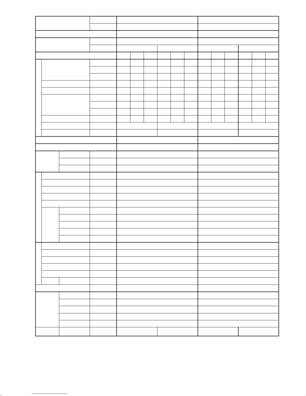
Indoor CS-S10PKH (S.E.ASIA) CS-S13PKH (S.E.ASIA)
Model
Outdoor CU-S10PKH (S.E.ASIA) CU-S13PKH (S.E.ASIA)
Performance Test Condition JIS JIS
Phase, Hz Single, 50 Single, 50
Power Supply
V 220 240 220 240
Min. Mid. Max. Min. Mid. Max. Min. Mid. Max. Min. Mid. Max.
kW 0.84 2.85 3.28 0.84 2.85 3.28 0.92 3.67 4.20 0.92 3.67 4.20
BTU/h 2860 9720 11200 2860 9720 11200 3140 12500 14300 3140 12500 14300
Capacity
kJ/h 3020 10260 11810 3020 10260 11810 3310 13210 15120 3310 13210 15120
Running Current A – 3.6 – – 3.3 – – 5.1 – – 4.6 –
Input Power W 225 730 920 225 730 920 260 1.01k 1.20k 260 1.01k 1.20k
W/W 3.73 3.90 3.57 3.73 3.90 3.57 3.54 3.63 3.50 3.54 3.63 3.50
BTU/hW 12.71 13.32 12.17 12.71 13.32 12.17 12.08 12.38 11.92 12.08 12.38 11.92
EER
kJ/hW 13.42 14.05 12.84 13.42 14.05 12.84 12.73 13.08 12.60 12.73 13.08 12.60
Power Factor % – 92 – – 92 – – 90 – – 91 –
Indoor Noise (H / L / QLo) dB-A 36 / 26 / 23 36 / 26 / 23 38 / 28 / 25 38 / 28 / 25
Cooling
Outdoor Noise (H / L / QLo) dB-A 46 / – / – 47 / – / – 47 / – / – 48 / – / –
Max Current (A) / Max Input Power (W) 5.6 / 1.12k 7.4 / 1.40k
Starting Current (A) 3.6 5.1
Type Hermetic Motor / Rotary Hermetic Motor / Rotary
Motor Type Brushless (6 poles) Brushless (6 poles)
Compressor
Output Power W 500 650
Type Cross-Flow Fan Cross-Flow Fan
Material ASG20K1 ASG20K1
Motor Type AC / Induction (4 poles) AC / Induction (4 poles)
Input Power W 51.0 - 58.0 51.0 - 58.0
Output Power W 24 24
QLo rpm 610 - 610 650 - 650
Lo rpm 680 - 680 720 - 720
Me rpm 840 - 840 910 - 910
Hi rpm 1000 - 1000 1100 - 1100
Indoor Fan
Speed
SHi rpm 1130 - 1130 1130 - 1130
Type Propeller Fan Propeller Fan
Material PP Resin PP Resin
Motor Type AC / Induction (6 poles) AC / Induction (6 poles)
Input Power W – –
Output Power W 30 25
Outdoor Fan
Speed Hi rpm 770 - 800 790 - 820
Moisture Removal L/h (Pt/h) 1.7 (3.6) 2.1 (4.4)
QLo m3/min (ft3/min) 5.5 (194) 5.6 (198)
Lo m3/min (ft3/min) 6.4 (226) 6.4 (251)
Me m3/min (ft3/min) 8.3 (293) 8.7 (307)
Hi m3/min (ft3/min) 10.1 (355) 10.9 (385)
Indoor
Airflow
SHi m
3
/min (ft3/min) 11.7 (413) 11.3 (399)
Outdoor
Airflow
Hi m
3
/min (ft3/min) 22.0 (780) 22.9 (810) 31.2 (1100) 32.6 (1150)
Page 16
16
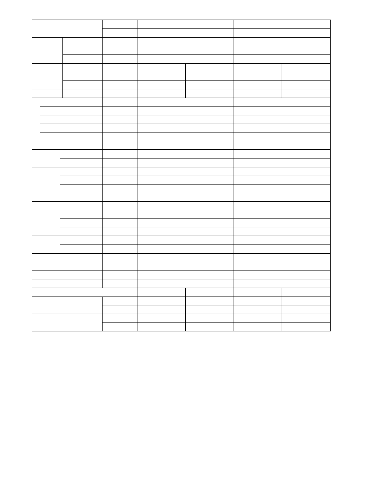
Indoor CS-S10PKH (S.E.ASIA) CS-S13PKH (S.E.ASIA)
Model
Outdoor CU-S10PKH (S.E.ASIA) CU-S13PKH (S.E.ASIA)
Control Device Capillary Tube Capillary Tube
Refrigerant Oil cm3 FV50S (250) FV50S (320)
Refrigeration
Cycle
Refrigerant Type g (oz) R410A, 740 (26.1) R410A, 690 (24.4)
Height (I/D / O/D) mm (inch) 290 (11-7/16) 511 (20-1/8) 290 (11-7/16) 542 (21-11/32)
Width (I/D / O/D) mm (inch) 870 (34-9/32) 650 (25-19/32) 870 (34-9/32) 780 (30-23/32)
Dimension
Depth (I/D / O/D) mm (inch) 214 (8-7/16) 230 (9-1/16) 214 (8-7/16) 289 (11-13/32)
Weight Net (I/D / O/D) kg (lb) 9 (20) 20 (44) 9 (20) 30 (66)
Pipe Diameter (Liquid / Gas) mm (inch) 6.35 (1/4) / 9.52 (3/8) 6.35 (1/4) / 12.70 (1/2)
Standard length m (ft) 7.5 (24.6) 7.5 (24.6)
Length range (min – max) m (ft) 3 (9.8) ~ 15 (49.2) 3 (9.8) ~ 15 (49.2)
I/D & O/D Height different m (ft) 5 (16.4) 5 (16.4)
Additional Gas Amount g/m (oz/ft) 15 (0.2) 15 (0.2)
Piping
Length for Additional Gas m (ft) 7.5 (24.6) 7.5 (24.6)
Inner Diameter mm 16.7 16.7
Drain Hose
Length mm 550 550
Fin Material Aluminium (Pre coated) Aluminium (Pre coated)
Fin Type Slit Fin Slit Fin
Row × Stage × FPI 2 × 15 × 17 2 × 15 × 17
Indoor Heat
Exchanger
Size (W × H × L) mm 610 × 315 × 25.4 610 × 315 × 25.4
Fin Material Aluminium (Blue coated) Aluminium (Blue coated)
Fin Type Slit Fin Louver Fin
Row × Stage × FPI 1.5 × 23 × 17 1 × 20 × 19
Outdoor
Heat
Exchanger
Size (W × H × L) mm 25.4 × 483.0 × 553.4:573.4 22.0 × 508.0 × 708.4
Material Polypropelene Polypropelene
Air Filter
Type One-touch One-touch
Power Supply Indoor Indoor
Power Supply Cord A 10 10
Thermostat – –
Protection Device – –
DRY BULB WET BULB DRY BULB WET BULB
Maximum °C 32 23 32 23
Indoor Operation Range
Minimum °C 16 11 16 11
Maximum °C 43 26 43 26
Outdoor Operation Range
Minimum °C 16 11 16 11
1. Cooling capacities are based on indoor temperature of 27°C DRY BULB (80.6°F DRY BULB), 19.0°C WET BULB (66°F WET BULB) and
outdoor air temperature of 35°C DRY BULB (95°F DRY BULB), 24°C WET BULB (75.2°F WET BULB)
Page 17
17
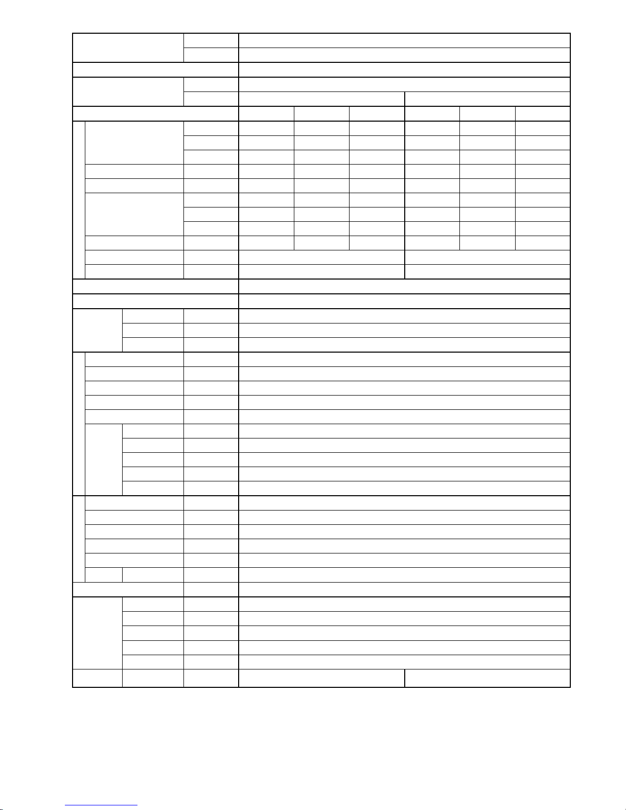
Indoor CS-S15PKH (S.E.ASIA)
Model
Outdoor CU-S15PKH (S.E.ASIA)
Performance Test Condition JIS
Phase, Hz Single, 50
Power Supply
V 220 240
Min. Mid. Max. Min. Mid. Max.
kW 1.07 4.40 5.00 1.07 4.40 5.00
BTU/h 3650 15000 17100 3650 15000 17100
Capacity
kJ/h 3850 15840 18000 3850 15840 18000
Running Current A – 6.0 – – 5.3 –
Input Power W 285 1.16k 1.36k 285 1.16k 1.36k
W/W 3.75 3.79 3.68 3.75 3.79 3.68
BTU/hW 12.81 12.93 12.57 12.81 12.93 12.57
EER
kJ/hW 13.51 13.66 13.24 13.51 13.66 13.24
Power Factor % – 88 – – 91 –
Indoor Noise (H / L / QLo) dB-A 43 / 30 / 27 43 / 30 / 27
Cooling
Outdoor Noise (H / L / QLo) dB-A 49 / – / – 50 / – / –
Max Current (A) / Max Input Power (W) 8.3 / 1.74k
Starting Current (A) 6.0
Type Hermetic Motor / Rotary
Motor Type Brushless (6 poles)
Compressor
Output Power W 700
Type Cross-Flow Fan
Material ASG20K1
Motor Type DC / Transistor (8-poles)
Input Power W 47.3 - 47.3
Output Power W 40
QLo rpm 710 - 710
Lo rpm 780 - 780
Me rpm 1010 - 1010
Hi rpm 1240 - 1240
Indoor Fan
Speed
SHi rpm 1340 - 1340
Type Propeller Fan
Material PP Resin
Motor Type AC / Induction (6 poles)
Input Power W –
Output Power W 30
Outdoor Fan
Speed Hi rpm 810 - 850
Moisture Removal L/h (Pt/h) 2.4 (5.1)
QLo m3/min (ft3/min) 6.6 (233)
Lo m3/min (ft3/min) 7.5 (265)
Me m3/min (ft3/min) 10.1 (357)
Hi m3/min (ft3/min) 12.8 (450)
Indoor
Airflow
SHi m
3
/min (ft3/min) 14.0 (494)
Outdoor
Airflow
Hi m
3
/min (ft3/min) 30.4 (1070) 31.6 (1120)
Page 18
18
Indoor CS-S15PKH (S.E.ASIA)
Model
Outdoor CU-S15PKH (S.E.ASIA)
Control Device Capillary tube
Refrigerant Oil cm3 FV50S (320)
Refrigeration
Cycle
Refrigerant Type g (oz) R410A, 950 (33.5)
Height (I/D / O/D) mm (inch) 290 (11-7/16) 542 (21-11/32)
Width (I/D / O/D) mm (inch) 870 (34-9/32) 780 (30-23/32)
Dimension
Depth (I/D / O/D) mm (inch) 214 (8-7/16) 289 (11-13/32)
Weight Net (I/D / O/D) kg (lb) 9 (20) 31 (68)
Pipe Diameter (Liquid / Gas) mm (inch) 6.35 (1/4) / 12.70 (1/2)
Standard length m (ft) 7.5 (24.6)
Length range (min – max) m (ft) 3 (9.8) ~ 15 (49.2)
I/D & O/D Height different m (ft) 5 (16.4)
Additional Gas Amount g/m (oz/ft) 15 (0.2)
Piping
Length for Additional Gas m (ft) 7.5 (24.6)
Inner Diameter mm 16.7
Drain Hose
Length mm 550
Fin Material Aluminium (Pre coated)
Fin Type Slit Fin
Row × Stage × FPI 2 × 15 × 21
Indoor Heat
Exchanger
Size (W × H × L) mm 610 × 315 × 25.4
Fin Material Aluminium (Blue coated)
Fin Type Slit Fin
Row × Stage × FPI 2 × 23 × 17
Outdoor Heat
Exchanger
Size (W × H × L) mm 25.4 × 504.0 × 693.4:713.4
Material Polypropelene
Air Filter
Type One-touch
Power Supply Indoor
Power Supply Cord A 10
Thermostat –
Protection Device –
DRY BULB WET BULB
Maximum °C 32 23
Indoor Operation Range
Minimum °C 16 11
Maximum °C 43 26
Outdoor Operation Range
Minimum °C 16 11
1. Cooling capacities are based on indoor temperature of 27°C DRY BULB (80.6°F DRY BULB), 19.0°C WET BULB (66°F WET BULB) and
outdoor air temperature of 35°C DRY BULB (95°F DRY BULB), 24°C WET BULB (75.2°F WET BULB)
Page 19
19
Indoor CS-S18PKH (S.E.ASIA) CS-S24PKH (S.E.ASIA)
Model
Outdoor CU-S18PKH (S.E.ASIA) CU-S24PKH (S.E.ASIA)
Performance Test Condition JIS JIS
Phase, Hz Single, 50 Single, 50
Power Supply
V 220 240 220 240
Min. Mid. Max. Min. Mid. Max. Min. Mid. Max. Min. Mid. Max.
kW 1.10 5.30 6.00 1.10 5.30 6.00 1.12 6.25 7.10 1.12 6.25 7.10
BTU/h 3750 18100 20500 3750 18100 20500 3820 21300 24200 3820 21300 24200
Capacity
kJ/h 3960 19080 21600 3960 19080 21600 4030 22500 25560 4030 22500 25560
Running Current A – 7.0 – – 6.4 – – 8.8 – – 8.2 –
Input Power W 290 1.44k 1.70k 290 1.44k 1.70k 320 1.88k 2.20k 320 1.88k 2.20k
W/W 3.79 3.68 3.53 3.79 3.68 3.53 3.50 3.32 3.23 3.50 3.32 3.23
BTU/hW 12.93 12.57 12.06 12.93 12.57 12.06 11.94 11.33 11.00 11.94 11.33 11.00
EER
kJ/hW 13.66 13.25 12.71 13.66 13.25 12.71 12.59 11.97 11.62 12.59 11.97 11.62
Power Factor % – 94 – – 94 – – 97 – – 96 –
Indoor Noise (H / L / QLo) dB-A 44 / 32 / 29 44 / 32 / 29 45 / 34 / 31 45 / 34 / 31
Cooling
Outdoor Noise (H / L / QLo) dB-A 49 / – / – 50 / – / – 51 / – / – 52 / – / –
Max Current (A) / Max Input Power (W) 10.5 / 2.19k 11.7 / 2.35k
Starting Current (A) 7.0 8.8
Type Hermetic Motor / Rotary Hermetic Motor / Rotary
Motor Type Brushless (6 poles) Brushless (6 poles)
Compressor
Output Power W 900 900
Type Cross-Flow Fan Cross-Flow Fan
Material ASG30K1 ASG30K1
Motor Type DC / Transistor (8-poles) DC / Transistor (8-poles)
Input Power W 94.8 - 94.8 94.8 - 94.8
Output Power W 40 40
QLo rpm 750 - 750 850 - 850
Lo rpm 820 - 820 920 - 920
Me rpm 1040 - 1040 1150 - 1150
Hi rpm 1260 - 1260 1370 - 1370
Indoor Fan
Speed
SHi rpm 1400 - 1400 1450 - 1450
Type Propeller Fan Propeller Fan
Material PP Resin PP Resin
Motor Type AC / Induction (6-poles) AC / Induction (6-poles)
Input Power W – –
Output Power W 30 74
Me rpm – –
Outdoor Fan
Speed
Hi rpm 900 - 930 810 - 840
Moisture Removal L/h (Pt/h) 2.9 (6.1) 3.5 (7.4)
QLo m3/min (ft3/min) 9.9 (350) 10.3 (364)
Lo m3/min (ft3/min) 11.0 (389) 11.4 (403)
Me m3/min (ft3/min) 14.4 (508) 14.6 (516)
Hi m3/min (ft3/min) 17.7 (625) 18.1 (640)
Indoor Airflow
SHi m
3
/min (ft3/min) 19.9 (703) 19.3 (682)
Outdoor Airflow Hi m3/min (ft3/min) 35.0 (1235) 36.2 (1280) 45.0 (1590) 46.6 (1645)
Page 20
20
Indoor CS-S18PKH (S.E.ASIA) CS-S24PKH (S.E.ASIA)
Model
Outdoor CU-S18PKH (S.E.ASIA) CU-S24PKH (S.E.ASIA)
Control Device Capillary Tube Capillary Tube
Refrigerant Oil cm3 FV50S (450) FV50S (450)
Refrigeration
Cycle
Refrigerant Type g (oz) R410A, 1.09k (38.5) R410A, 1.29k (45.5)
Height (I/D / O/D) mm (inch) 290 (11-7/16) 619 (24-3/8) 290 (11-7/16) 695 (27-3/8)
Width (I/D / O/D) mm (inch) 1070 (42-5/32) 824 (32-15/32) 1070 (42-5/32) 875 (34-15/32)
Dimension
Depth (I/D / O/D) mm (inch) 240 (9-15/32) 299 (11-25/32) 240 (9-15/32) 320 (12-5/8)
Weight Net (I/D / O/D) kg (lb) 12 (26) 32 (71) 12 (26) 44 (97)
Pipe Diameter (Liquid / Gas) mm (inch) 6.35 (1/4) / 12.70 (1/2) 6.35 (1/4) / 15.88 (5/8)
Standard length m (ft) 5.0 (16.4) 5.0 (16.4)
Length range (min – max) m (ft) 3 (9.8) ~ 20 (65.6) 3 (9.8) ~ 20 (65.6)
I/D & O/D Height different m (ft) 15 (49.2) 15 (49.2)
Additional Gas Amount g/m (oz/ft) 15 (0.2) 20 (0.2)
Piping
Length for Additional Gas m (ft) 10 (32.8) 10 (32.8)
Inner Diameter mm 16.7 16.7
Drain Hose
Length mm 550 550
Fin Material Aluminium (Pre Coated) Aluminium (Pre Coated)
Fin Type Slit Fin Slit Fin
Row × Stage × FPI 2 × 15 × 17 2 × 15 × 21
Indoor Heat
Exchanger
Size (W × H × L) mm 810 × 315 × 25.4 810 × 315 × 25.4
Fin Material Aluminium (Blue Coated) Aluminium (Blue Coated)
Fin Type Slit Fin Slit Fin
Row × Stage × FPI 1.5 × 16:28 × 17 2 × 31 × 17
Outdoor Heat
Exchanger
Size (W × H × L) mm 25.4 × 336:588 × 775.4:795.3 25.4 × 651 × 640
Material Polypropelene Polypropelene
Air Filter
Type One-touch One-touch
Power Supply Indoor Indoor
Power Supply Cord A 15 20
Thermostat – –
Protection Device – –
Dry Bulb Wet Bulb Dry Bulb Wet Bulb
Maximum °C 32 23 32 23
Indoor Operation Range
Minimum °C 16 11 16 11
Maximum °C 43 26 43 26
Outdoor Operation Range
Minimum °C 16 11 16 11
1. Cooling capacities are based on indoor temperature of 27°C DRY BULB (80.6°F DRY BULB), 19.0°C WET BULB (66°F WET BULB) and
outdoor air temperature of 35°C DRY BULB (95°F DRY BULB), 24°C WET BULB (75.2°F WET BULB)
Page 21
21
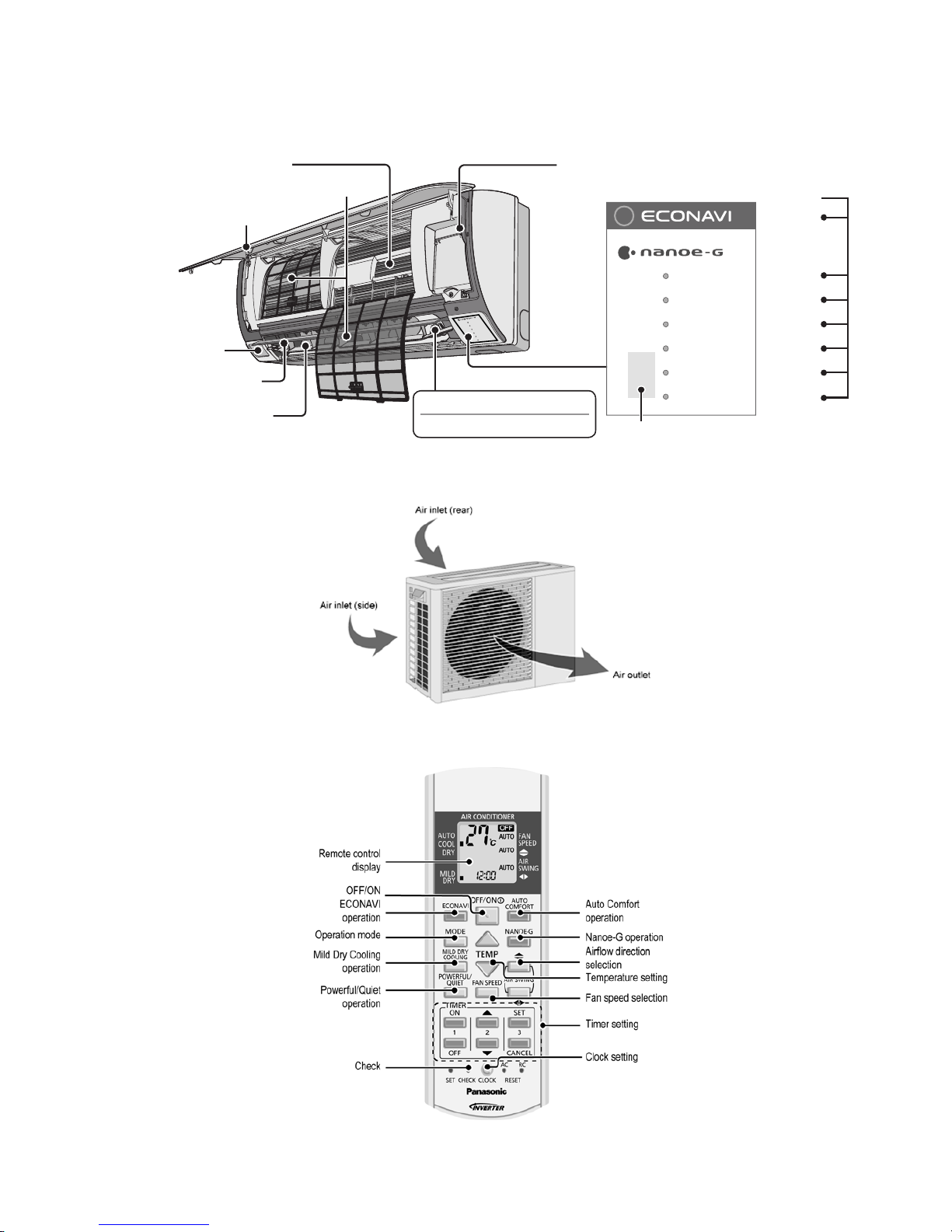
3. Location of Controls and Components
3.1 Indoor Unit
Human Activity Sens or
A
luminium Fin
Front panel
V
ertical airflow direc tion louver
• Do not adj ust by hand.
Auto OFF/ON button
• Use when remote control is misplaced or a malfunction occurs
Horizontal airflow direction louver
• Do not adjust by hand.
P
O
W
E
R
T
I
M
E
R
A
U
T
O
C
O
M
F
O
R
T
N
A
N
O
E
-
G
P
O
W
ER
F
U
L
Q
U
I
E
T
Air Filters
nanoe-G GENERATOR
• Do not to u c h du ri n g operation.
Indicator
(Green)
(Green)
(Orange)
(Green)
(Blue)
(Orange)
(Green)
POWER
TIMER
AUTO COMFORT
NANOE- G
POWERFUL
QUIET
Sunlight se ns o r an d r em o t e c o ntrol receiver
3.2 Outdoor Unit
3.3 Remote Control
Page 22
22
4. Dimensions
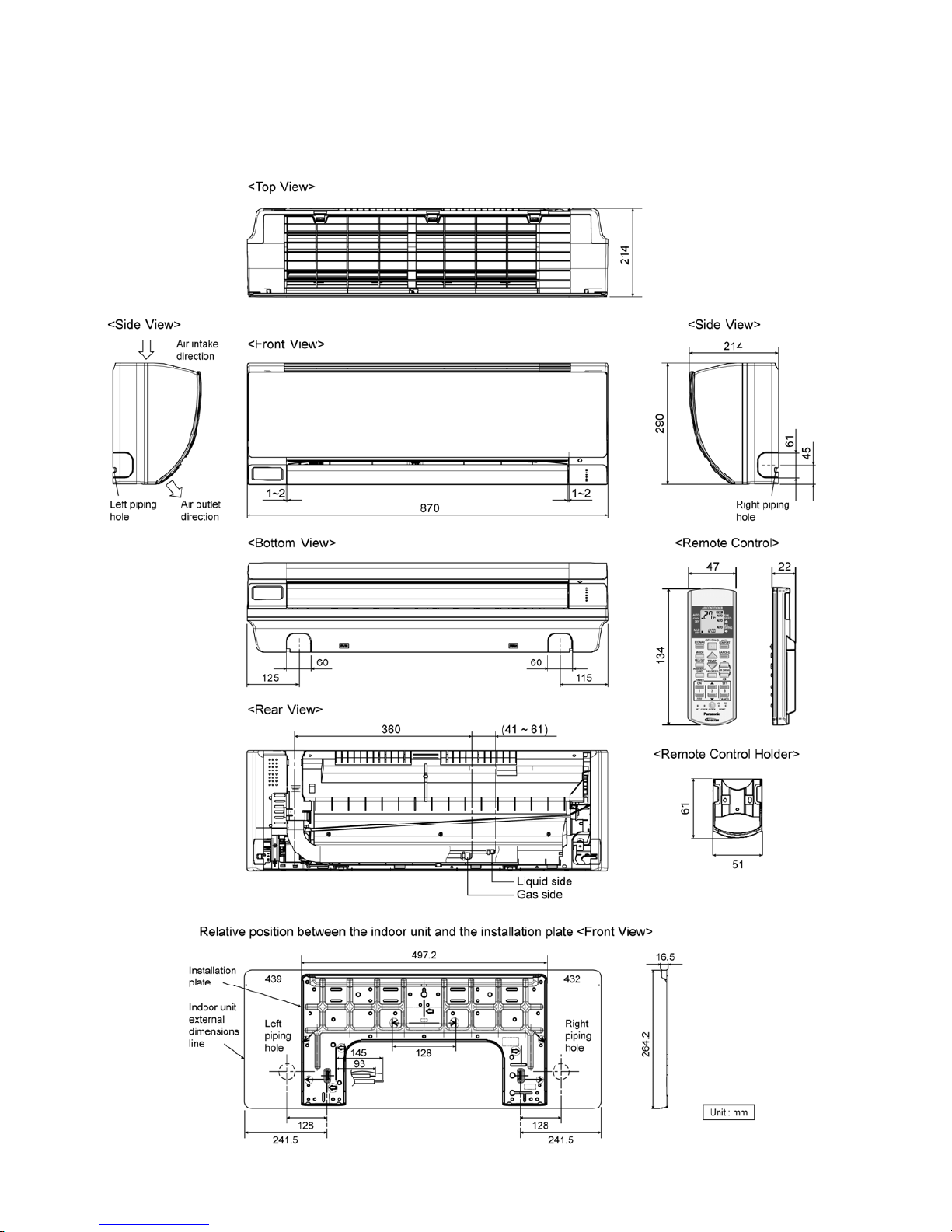
4.1 Indoor Unit
4.1.1 CS-S10PK CS-S13PK CS-S15PK
Page 23
23
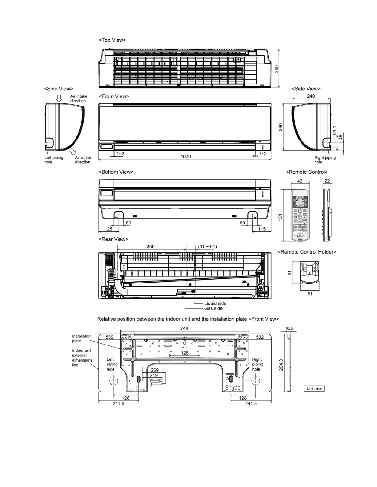
4.1.2 CS-S18PK CS-S24PK
Page 24
24
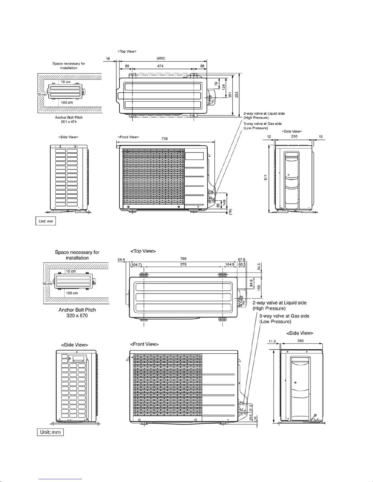
4.2 Outdoor Unit
4.2.1 CU-S10PK
4.2.2 CU-S13PK CU-S15PK
542
Page 25
25
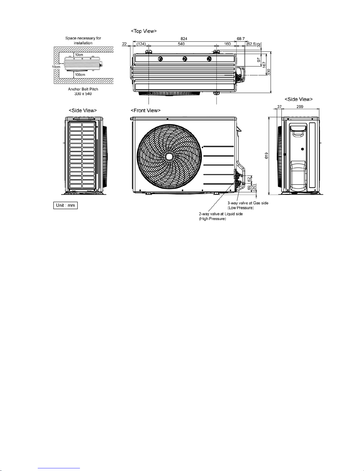
4.2.3 CU-S18PK
Page 26
26
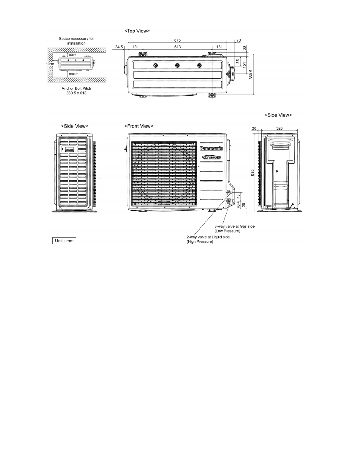
4.2.4 CU-S24PK
Page 27
27
5. Refrigeration Cycle Diagram
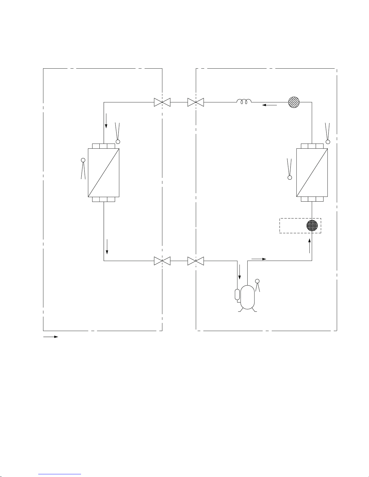
5.1 CS-S10PK CU-S10PK CS-S13PK CU-S13PK CS-S15PK CU-S15PK
INDOOR OUTDOOR
INTAKE
TEMP.
SENSOR
PIPE
TEMP.
SENSOR
INTAKE
TEMP.
SENSOR
PIPE
TEMP.
SENSOR
LIQUID
SIDE
2-WAY
VALV E
3-WAY
VALV E
GAS
SIDE
COOLING
HEAT EXCHANGER
(EVAPORATOR)
HEAT EXCHANGER
(CONDENSER)
COMPRESSOR
TEMP. SENSOR
STRAINER
MUFFLER
CAPILLARY TUBE
CU-S15PK only
COMPRESSOR
Page 28
28
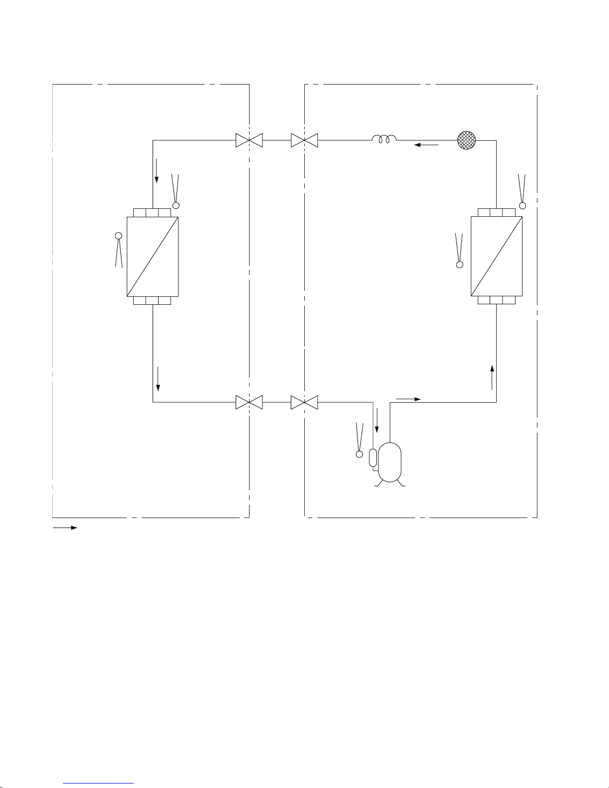
5.2 CS-S18PK CU-S18PK CS-S24PK CU-S24PK
INDOOR OUTDOOR
INTAKE
TEMP.
SENSOR
PIPE
TEMP.
SENSOR
INTAKE
TEMP.
SENSOR
PIPE
TEMP.
SENSOR
LIQUID
SIDE
2-WAY
VALV E
3-WAY
VALVE
GAS
SIDE
COOLING
HEAT EXCHANGER
(EVAPORATOR)
HEAT EXCHANGER
(CONDENSER)
COMPRESSOR
TEMP.
SENSOR
STRAINERCAPILLARY TUBE
COMPRESSOR
Page 29
29
6. Block Diagram
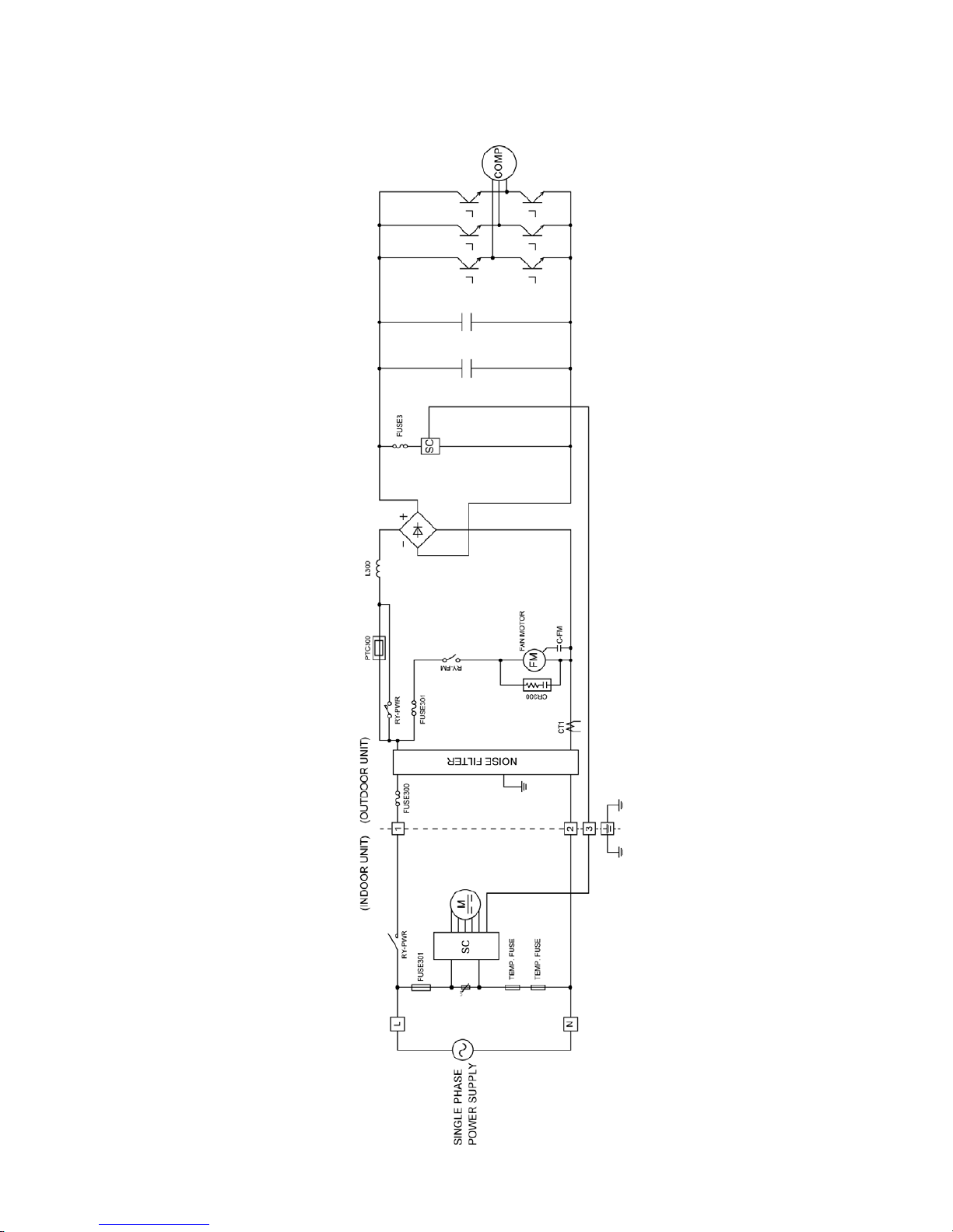
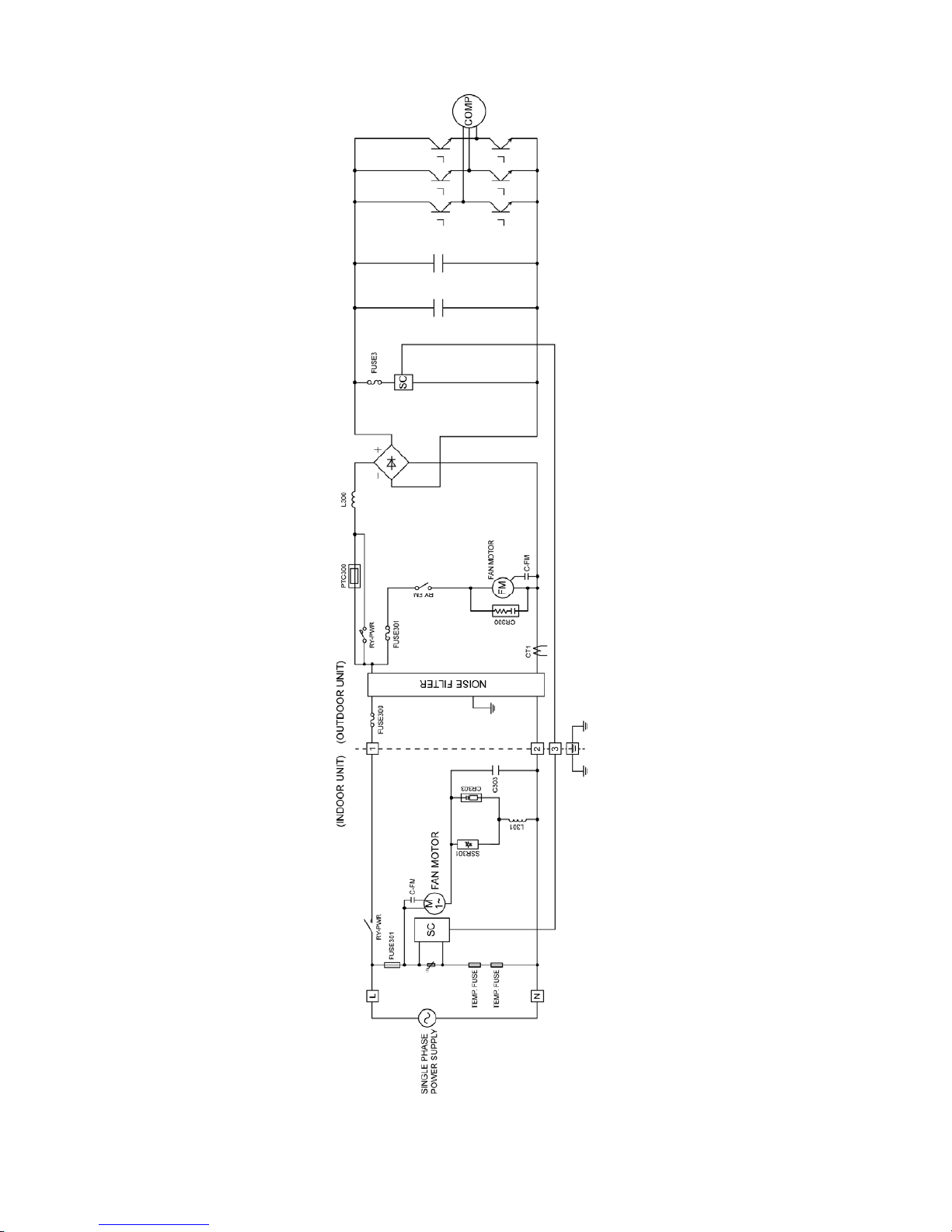
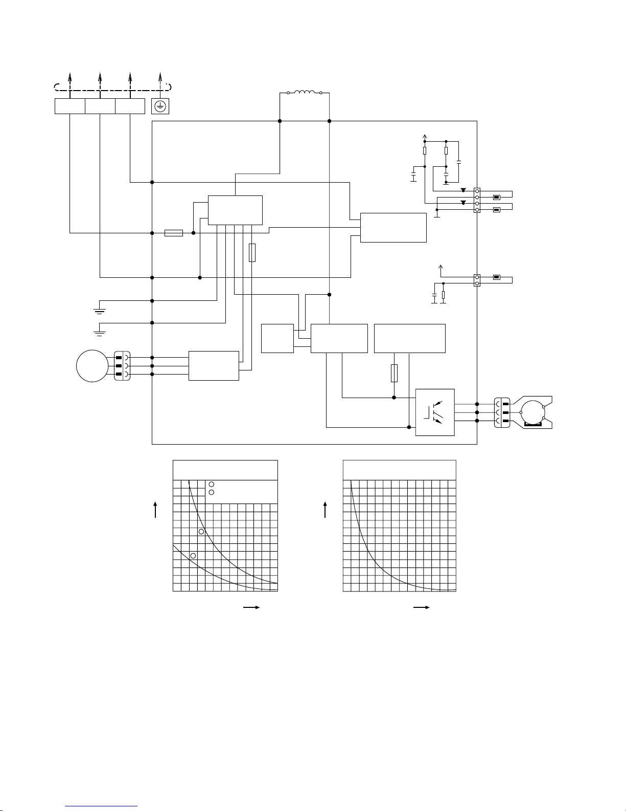
6.1 CS-S10PKH CU-S10PKH (Malaysia only)
Page 30
30
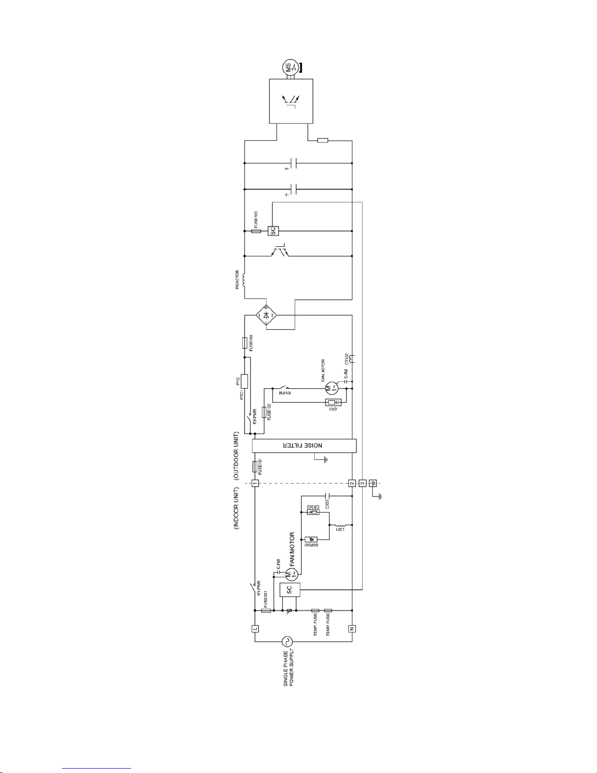
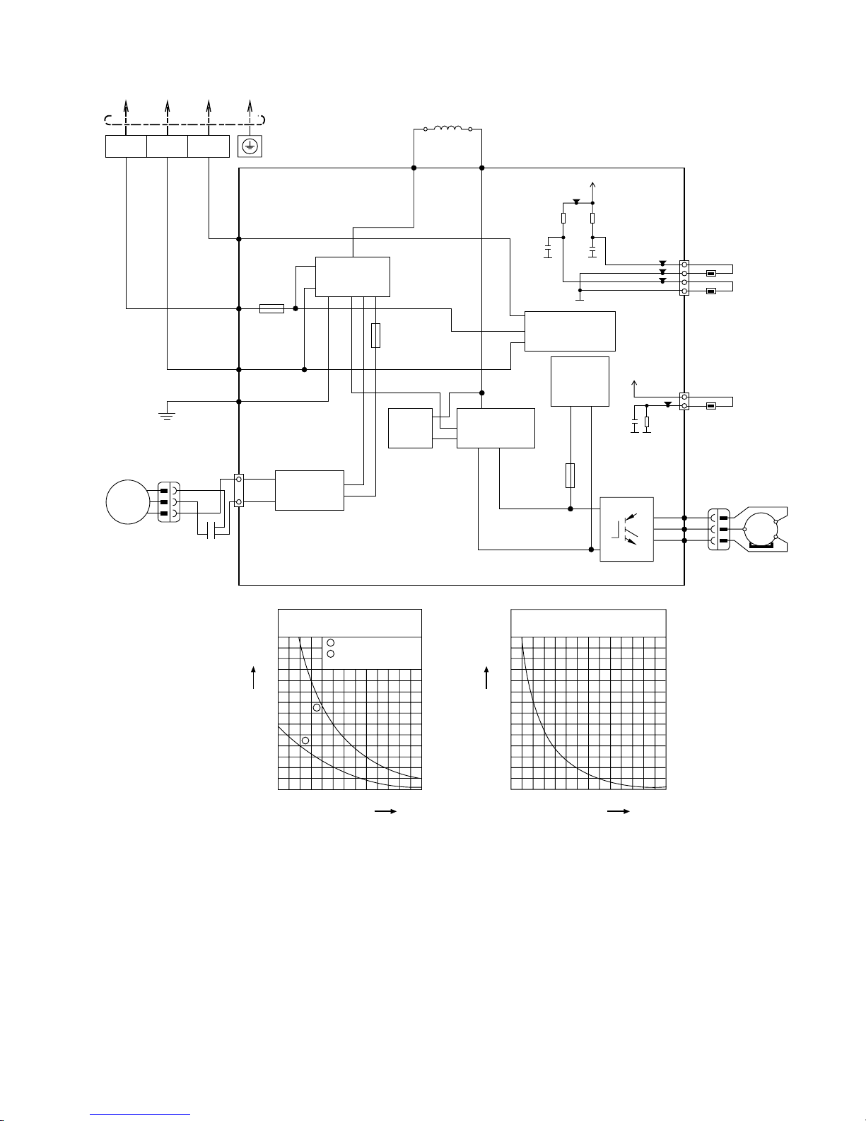
6.2 CS-S10PK CU-S10PK (except Malaysia)
Page 31
31
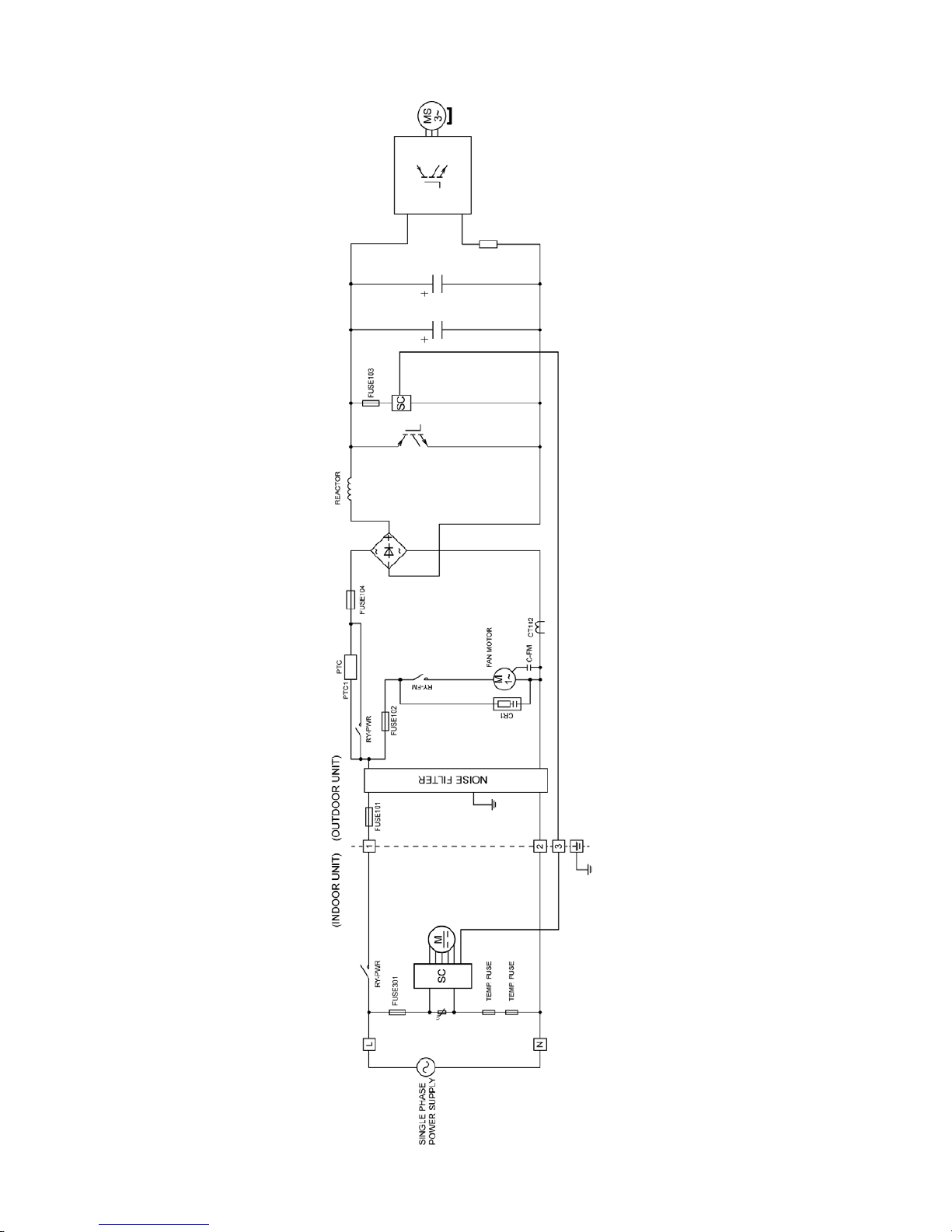
6.3 CS-S13PK CU-S13PK
Page 32
32
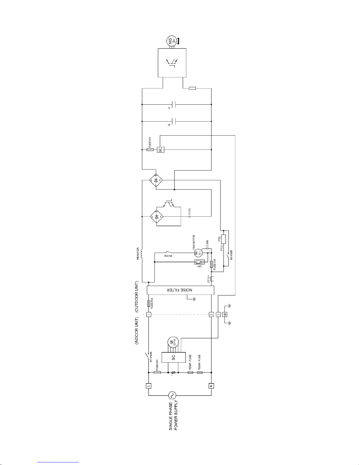
6.4 CS-S15PK CU-S15PK
Page 33
33
6.5 CS-S18PK CU-S18PK
Page 34
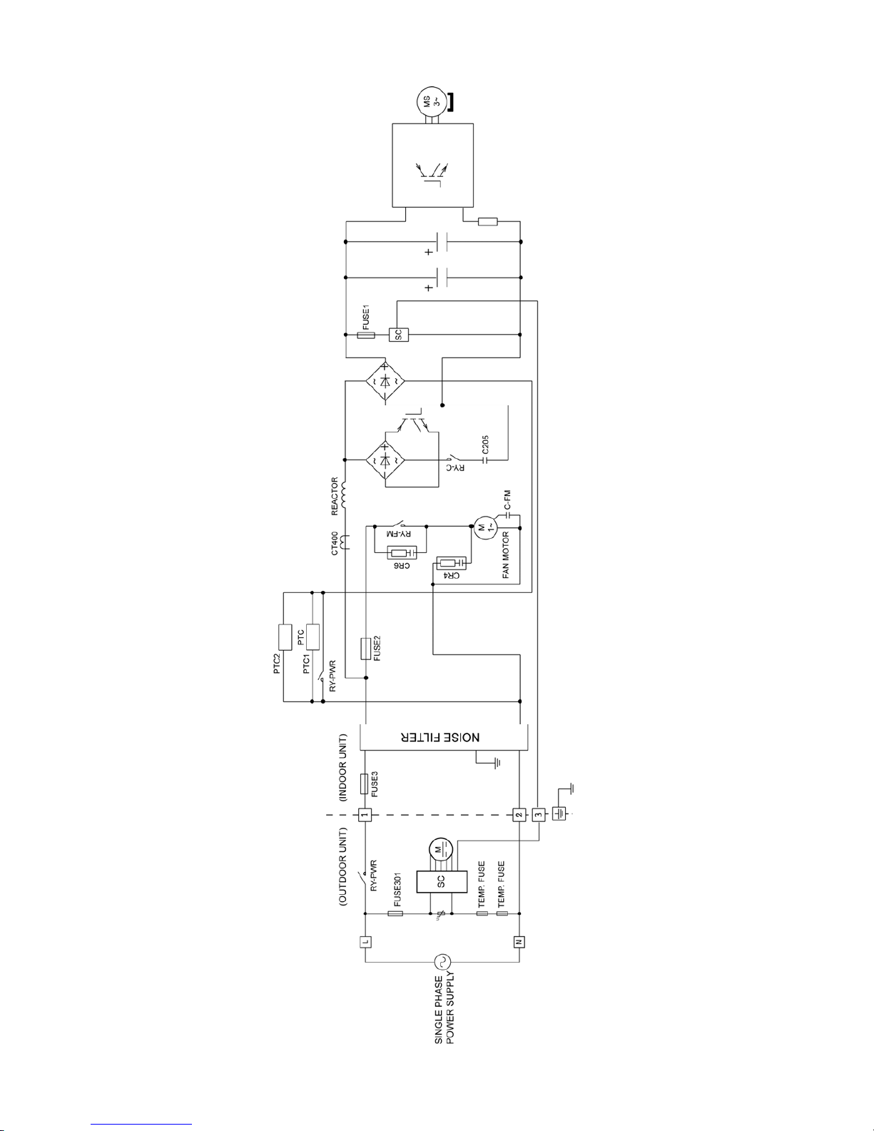
34
6.6 CS-S24PK CU-S24PK
Page 35
35
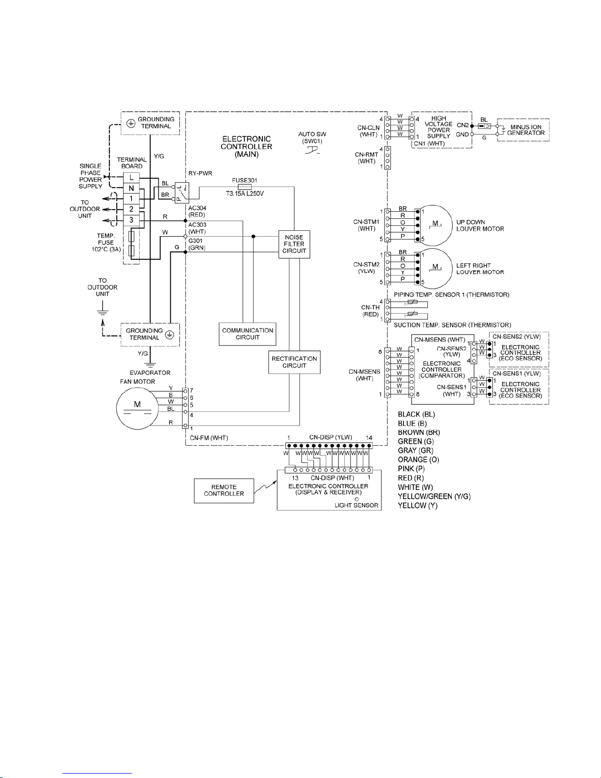
7. Wiring Connection Diagram
7.1 Indoor Unit
7.1.1 CS-S10PKH (Malaysia only) CS-S15PK CS-S18PK CS-S24PK
Page 36
36
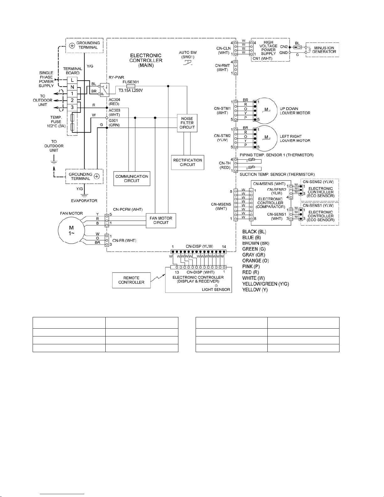
7.1.2 CS-S10PK (except Malaysia) CS-S13PK
Resistance of Indoor Fan Motor Windings
Resistance of Indoor Fan Motor Windings
MODEL CS-S13PKH (Malaysia only) MODEL
CS-S10PKH / CS-S13PKH
(except Malaysia)
CONNECTION CWA921441 CONNECTION CWA921442
BLUE-YELLOW 366Ω BLUE-YELLOW 407.7Ω
BLUE-RED 338Ω BLUE-RED 370.6Ω
Note: Resistance at 20°C of ambient temperature. Note: Resistance at 20°C of ambient temperature.
Page 37
37
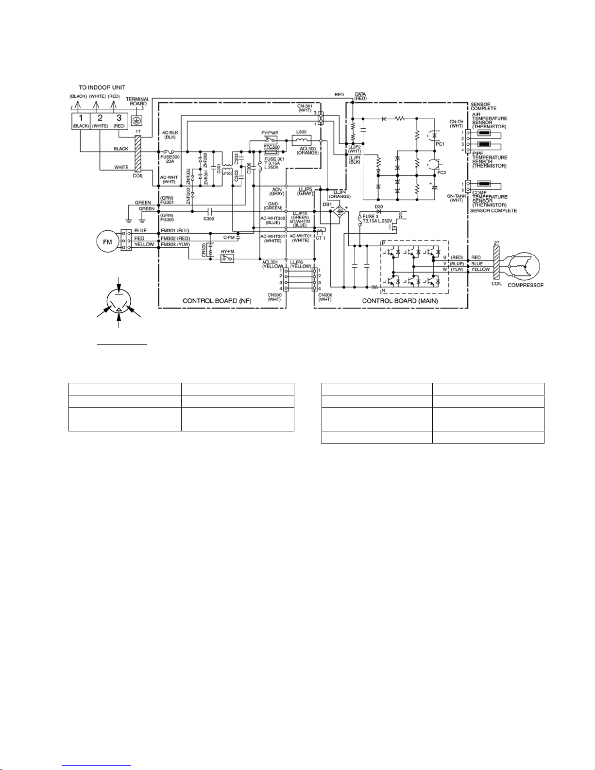
7.2 Outdoor Unit
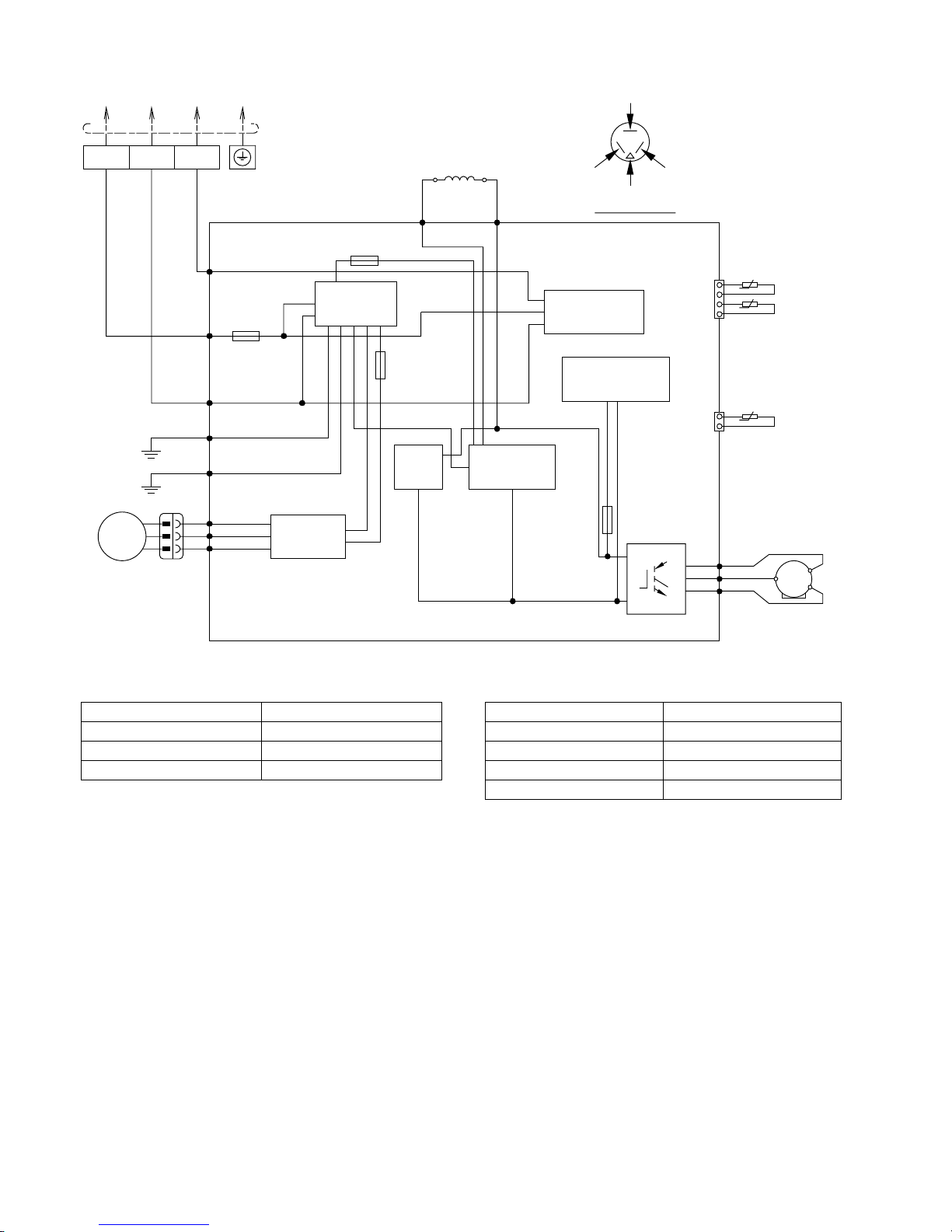
7.2.1 CU-S10PK
RED (RED)
TRADE MARK
BLUE (BLU)
YELLOW (YLW)
COMP. TERMINAL
Resistance of Outdoor Fan Motor Windings
Resistance of Compressor Windings
MODEL CU-S10PK MODEL CU-S10PK
CONNECTION CWA951702 CONNECTION 5SS072XGA21
BLUE-YELLOW 309.5Ω U-V 3.034Ω
BLUE-RED 225Ω U-W 3.021Ω
Note: Resistance at 20°C of ambient temperature. V-W 3.009Ω
Note: Resistance at 20°C of ambient temperature.
Page 38
38
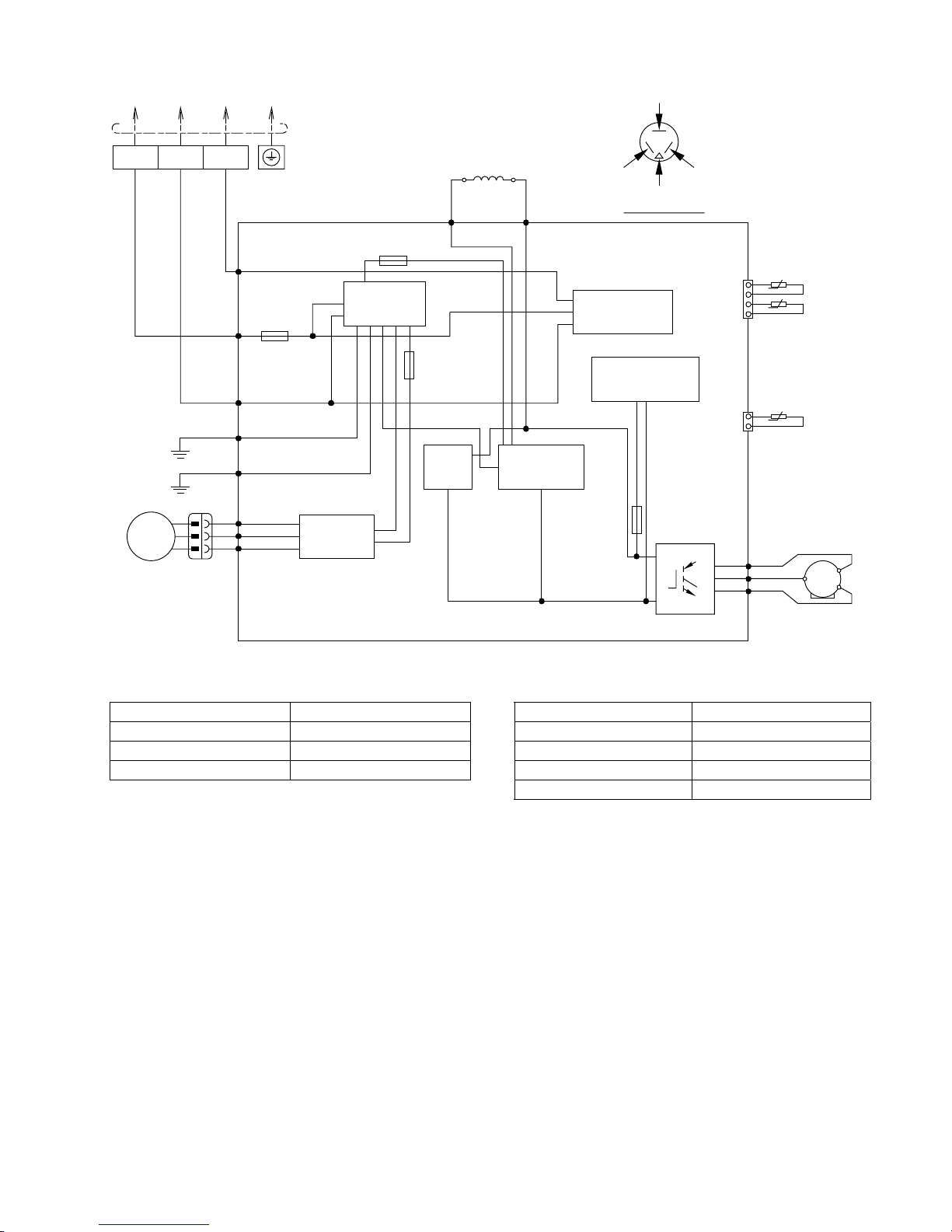
7.2.2 CU-S13PK
TERMINAL
BOARD
TO INDOOR UNIT
COMPRES SOR
FAN MOTOR
OUTDOOR AIR TEMP.
SENSOR ( THERMISTOR)
PIPING TEMP.
SENSOR ( THERMISTOR)
1
2
3
4
CN-TH
(WHT)
t
0
t
0
AC-WHT
(WHT)
FG1
(GRN)
FG2
(GRN)
GRN
BLK
WHT
GRN
AC-BLK
(BLK)
DATA
(RED)
RED
GRY
(GRY) (GRY)
RAT2
GRY
RAT1
REACTOR
RED
BLU
YLW
(RED)
FUSE103
T3.15A L250V
(BLU)
(YLW)
U
V
W
COMP. TEMPERATURE
SENSOR ( THERMISTOR)
1
3
CN-TANK
(WHT)
t
0
MS
3~
P
N
SWITCHING POWER
SUPPLY CIRCUIT
FUSE102
T3.15A L250V
BLU
RED
YLW
FM1 (BLU)
FM2 (RED)
FM3 (YLW)
M
1~
FAN MOTOR
CIRC UIT
FUSE101
(20A 250V)
RED (RED)
TRADE MARK
BLUE (BLU)
YELLOW (YLW)
COMP. TERMINA L
3
(RED)
2
(WHITE)
1
(BLACK)
NOISE FILTER
CIRC UIT
COMMUNICATION
CIRCUIT
PFC
CIRCUIT
ELECTRONIC CONTROLLER
FUSE104
(1 5A 2 50V)
RECTIFICATION
CIRCUIT
Resistance of Outdoor Fan Motor Windings
Resistance of Compressor Windings
MODEL CU-S13PK MODEL CU-S13PK
CONNECTION CWA951703 CONNECTION 5RS092XCE21
BLUE-YELLOW 275Ω U-V 1.152Ω
BLUE-RED 247Ω U-W 1.152Ω
Note: Resistance at 20°C of ambient temperature. V-W 1.152Ω
Note: Resistance at 20°C of ambient temperature.
Page 39
39
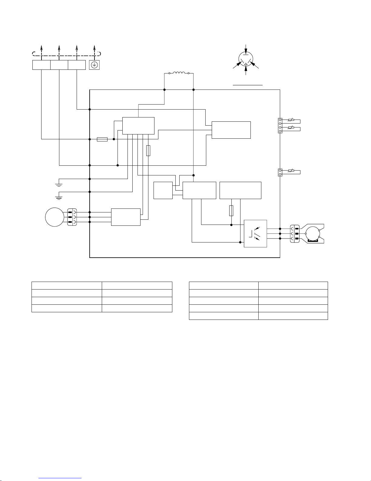
7.2.3 CU-S15PK
TERMINAL
BOARD
TO INDOOR UNIT
COMPRES SOR
FAN MOTOR
OUTDOOR AIR TEMP.
SENSOR ( THERMISTOR)
PIPING TEMP.
SENSOR ( THERMISTOR)
1
2
3
4
CN-TH
(WHT)
t
0
t
0
AC-WHT
(WHT)
FG1
(GRN)
FG2
(GRN)
GRN
BLK
WHT
GRN
AC-BLK
(BLK)
DATA
(RED)
RED
GRY
(GRY) (GRY)
RAT2
GRY
RAT1
REACTOR
RED
BLU
YLW
(RED)
FUSE103
T3.15A L250V
(BLU)
(YLW)
U
V
W
COMP. TEMPERATURE
SENSOR ( THERMISTOR)
1
3
CN-TANK
(WHT)
t
0
MS
3~
P
N
SWITCHING POWER
SUPPLY CIRCUIT
FUSE102
T3.15A L250V
BLU
RED
YLW
FM1 (BLU)
FM2 (RED)
FM3 (YLW)
M
1~
FAN MOTOR
CIRC UIT
FUSE101
(20A 250V)
RED (RED)
TRADE MARK
BLUE (BLU)
YELLOW (YLW)
COMP. TERMINA L
3
(RED)
2
(WHITE)
1
(BLACK)
NOISE FILTER
CIRC UIT
COMMUNICATION
CIRCUIT
PFC
CIRCUIT
ELECTRONIC CONTROLLER
FUSE104
(1 5A 2 50V)
RECTIFICATION
CIRCUIT
Resistance of Outdoor Fan Motor Windings
Resistance of Compressor Windings
MODEL CU-S15PK MODEL CU-S15PK
CONNECTION CWA951699 CONNECTION 5RS102XBC21
BLUE-YELLOW 264Ω U-V 0.858Ω
BLUE-RED 250Ω U-W 0.858Ω
Note: Resistance at 20°C of ambient temperature. V-W 0.858Ω
Note: Resistance at 20°C of ambient temperature.
Page 40
40
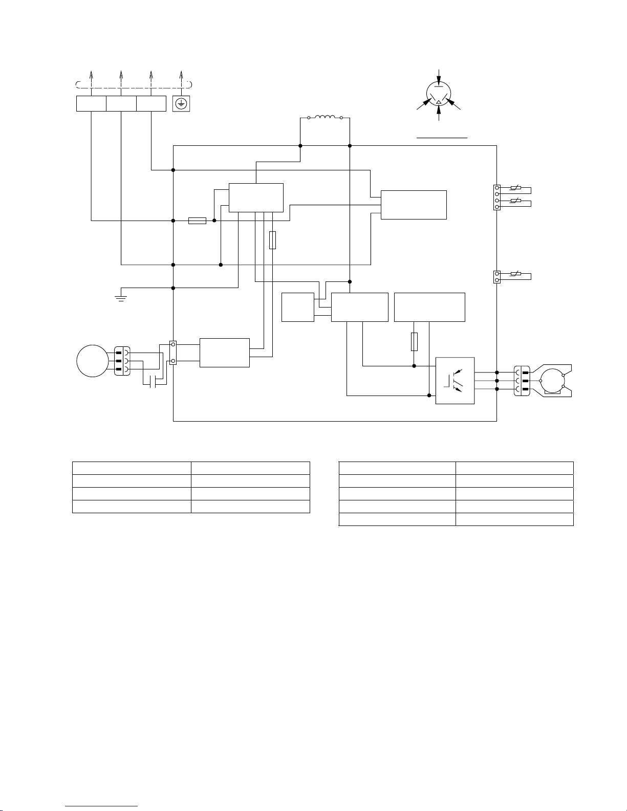
7.2.4 CU-S18PK
OUTDOOR AIR TEMP.
SENSOR (THERMISTOR)
PIPING TEMP.
SENSOR (THERMISTOR)
COMP. TEMPERATURE
SENSOR (THERMISTOR)
TERMINAL
BOARD
TO INDOOR UNIT
AC-WHT
(WHT)
FG1
(GRN)
GRN
BLK
WHT
AC-BLK
(BLK)
DATA
(RED)
RED
GRY
RAT2
(GRY)
RAT1
(GRY)
GRY
REACTOR
(RED)
FUSE 101
T3.15A L250V
(BLU)
(YLW)
U
V
W
P
N
RECTIFICATION
CIRCUIT
FUSE 104
T3.15A L250V
FUSE 103
(20A 250V)
3
(RED)
2
(WHITE)
1
(BLACK)
COMMUNICATION
CIRCUIT
PFC
CIRCUIT
3
4
CN-TH1
(WHT)
1
2
1
3
CN-TANK
(WHT)
SWITCHING POWER
SUPPLY CIRCUIT
COMPRESSOR
RED
BLU
YLW
MS
3 ~
BLU
YLW
RED
FAN MOTOR
M
1~
t
0
t
0
t
0
TRADE MARK
BLUE
(BLU) OR (R)
RED
(RED) OR (S)
YELLOW
(YEL) OR (C)
COMP. TERMINAL
FM1 (BLU)
FM2 (RED)
FM3 (YLW)
FAN MOTOR
CIRCUIT
FG2
(GRN)
GRN
NOISE FILTER
CIRCUIT
ELECTRONIC CONTROLLER
Resistance of Outdoor Fan Motor Windings
Resistance of Compressor Windings
MODEL CU-S18PK MODEL CU-S18PK
CONNECTION CWA951830 CONNECTION 5RD132XGA21
BLUE-YELLOW 247Ω U-V 1. 276Ω
BLUE-RED 254Ω U-W 1. 276Ω
Note: Resistance at 20°C of ambient temperature. V-W 1. 276Ω
Note: Resistance at 20°C of ambient temperature.
Page 41
41
7.2.5 CU-S24PK
5
1
TERMINAL
BOARD
TO INDOOR UNIT
AC-WHT
(WHT)
CN-ACFM
(WHT)
FG01
(GRN)
GRN
BLK
WHT
AC-BLK
(BLK)
COM3
(RED)
RED
GRY
L2-1
GRY
L2-0
REACTOR
(RED)
FUSE1
T2.50A L250V
(BLU)
(YLW)
U
V
W
P
N
RECTIFICATION
CIRCUIT
FUSE2
T3.15A L250V
FAN MOTOR
CIRCUIT
FUSE3
(20A 250V)
3
(RED)
2
(WHITE)
1
(BLACK)
NOISE FILTER
CIRCUIT
COMMUNICATION
CIRCUIT
PFC
CIRCUIT
3
4
CN-TH1
(WHT)
1
2
1
3
CN-TANK
(WHT)
SWITCHING POWER
SUPPLY CIRCUIT
COMPRESSOR
RED
BLU
YLW
MS
3 ~
BLU
YLW
RED
FAN MOTOR
M
1~
BLU
CAPACITOR
OUTDOOR AIR TEMP.
SENSOR ( THERMISTOR)
SENSOR
COMPLETE
SENSOR
COMPLETE
PIPING TEMP.
SENSOR ( THERMISTOR)
t
0
t
0
COMP. TEMP ERATURE
SENSOR ( THERMISTOR)
t
0
RED (RED)
TRADE MARK
BLUE (BLU)
YELLOW (YLW)
COMP. TERMINAL
ELECTRONIC CONTROLLER
Resistance of Outdoor Fan Motor Windings
Resistance of Compressor Windings
MODEL CU-S24PK MODEL CU-S24PK
CONNECTION CWA951879 CONNECTION 5RD132XHA21
BLUE-YELLOW 85.7Ω U-V 1. 276Ω
BLUE-RED 98.0Ω U-W 1. 276Ω
Note: Resistance at 20°C of ambient temperature. V-W 1. 276Ω
Note: Resistance at 20°C of ambient temperature.
Page 42
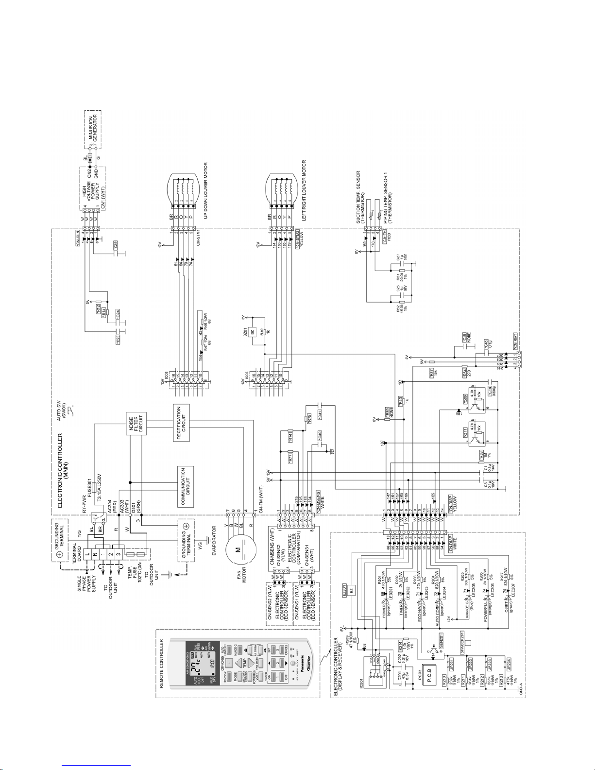
42
8. Electronic Circuit Diagram
8.1 Indoor Unit
8.1.1 CS-S10PKH (Malaysia only) CS-S15PK CS-S18PK CS-S24PK
Page 43
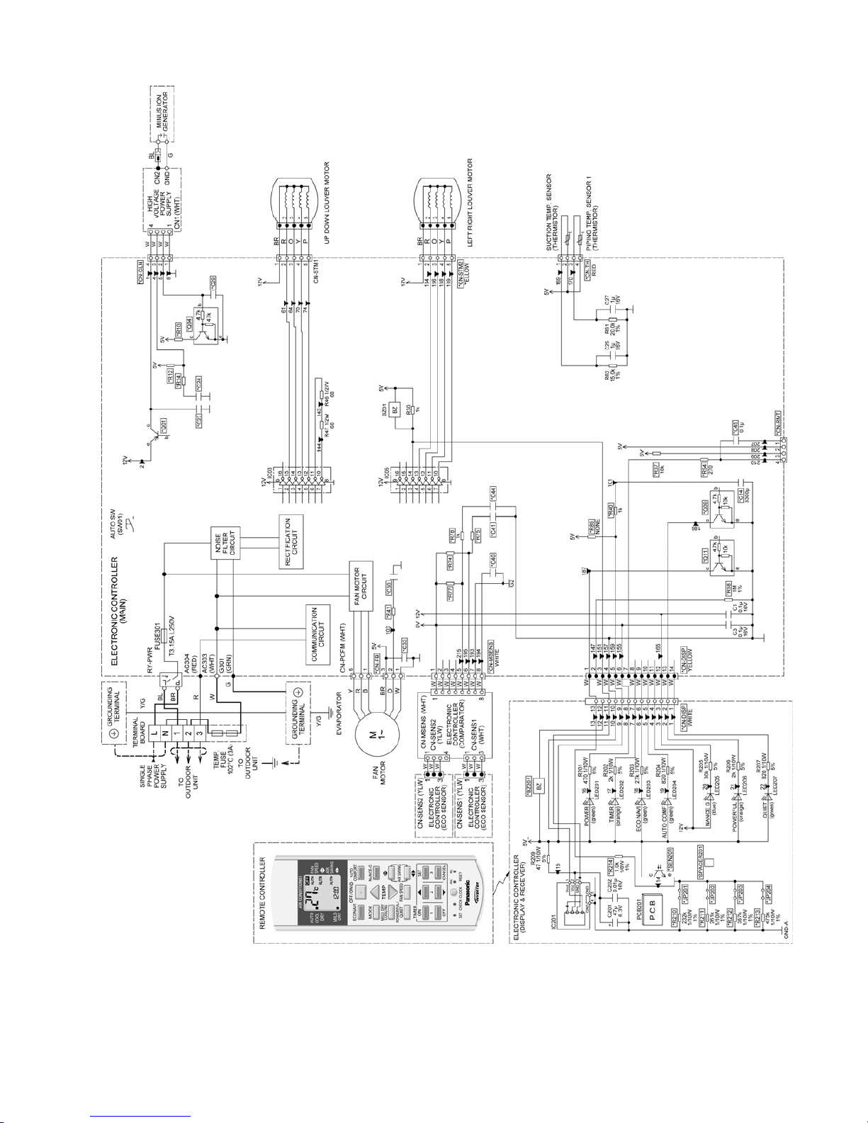
43
8.1.2 CS-S10PK (except Malaysia) CS-S13PK
Page 44
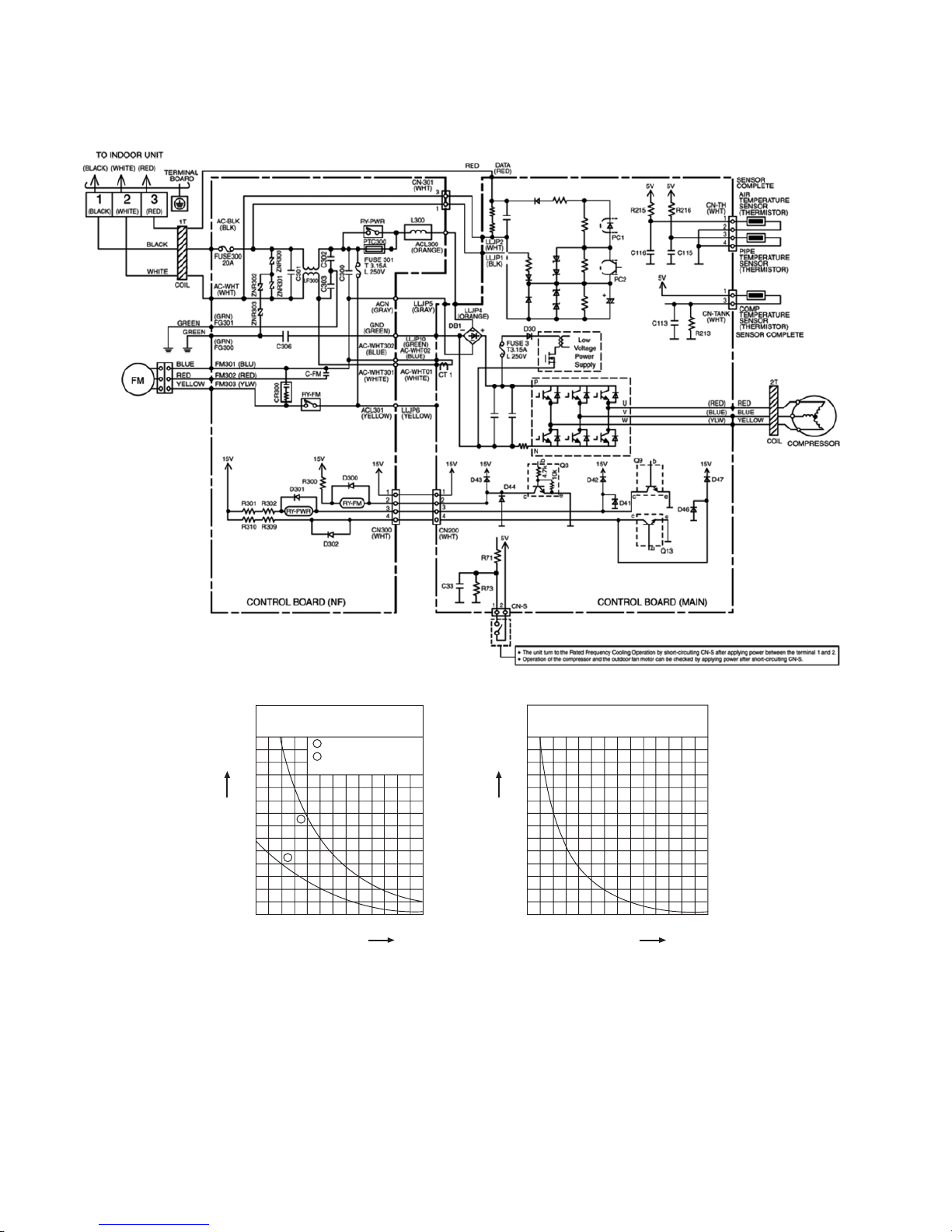
44
8.2 Outdoor Unit
8.2.1 CU-S10PK
Sensor (Thermistor)
Characteristics
70
60
50
40
30
20
10
0
-10 0 10
Temperature (
o
C)
Resistance ( kΩ)
20 30 40 50
1
2
1
2
Outdoor Air Sensor
Outdoor Heat Exchanger
Sensor
Compressor Temp. Sensor
(Thermistor) Characteristics
70
60
50
40
30
20
10
0
20 40 60
Temperature (
o
C)
Resistance ( kΩ)
80 100 120 140
Page 45
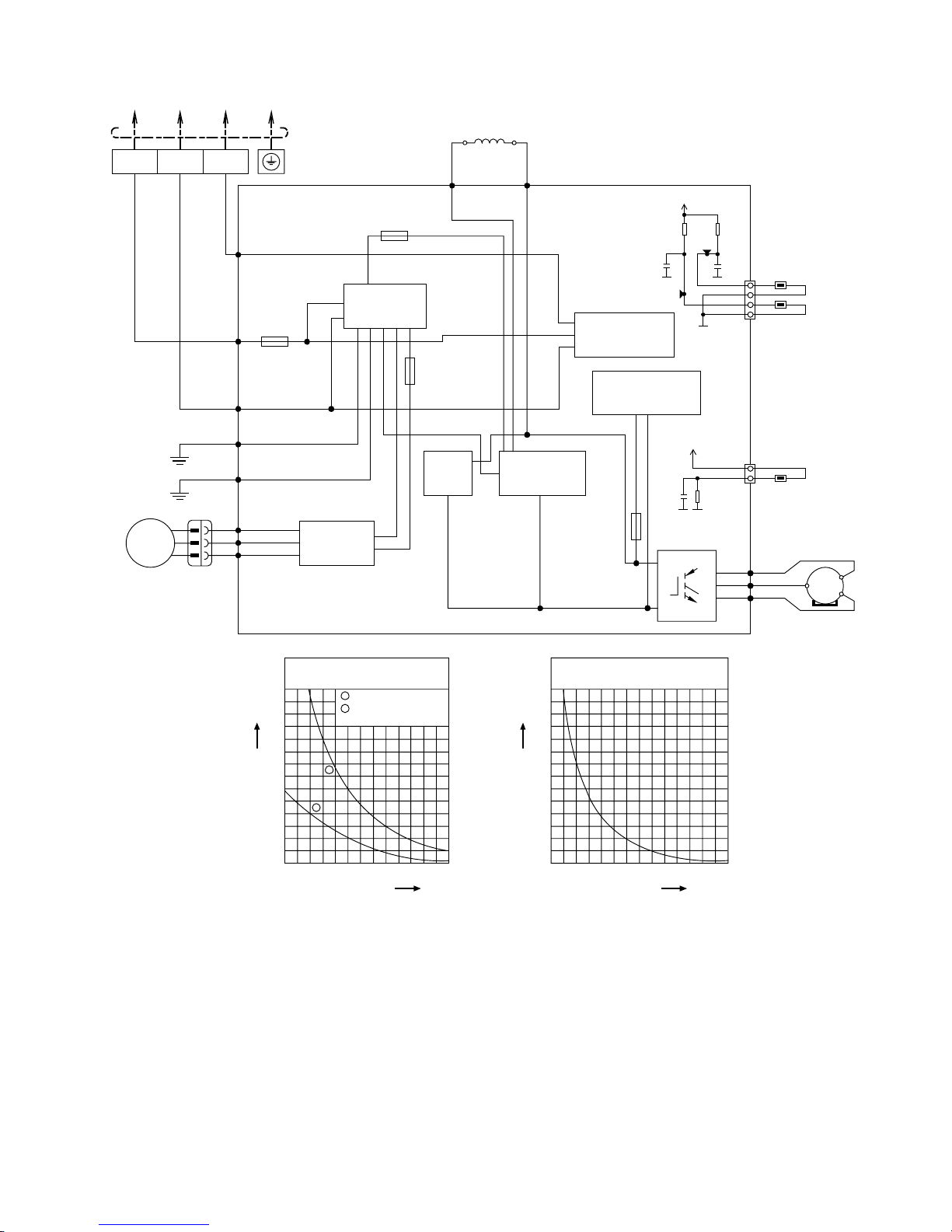
45
8.2.2 CU-S13PK CU-S15PK
TERMINAL
BOARD
TO INDOOR UNIT
COMPRES SOR
FAN MOTOR
AC-WHT
(WHT)
FG1
(GRN)
FG2
(GRN)
GRN
BLK
WHT
GRN
AC-BLK
(BLK)
DATA
(RED)
RED
GRY
RAT2
GRY
RAT1
REACTOR
RED
BLU
YLW
(RED)
FUSE103
T3.15A L250V
(BLU)
(YLW)
U
V
W
MS
3~
P
N
SWITCHING POWER
SUPPLY CIRCUIT
FUSE102
T3.15A L250V
BLU
RED
YLW
FM1 (BLU)
FM2 (RED)
FM3 (YLW)
M
1~
FAN MOTOR
CIRCUIT
FUSE101
(20A 2 50V)
3
(RED)
2
(WHITE)
1
(BLACK)
NOISE FILTER
CIRCUIT
COMMUNICATION
CIRCUIT
PFC
CIRCUIT
RECTIFICATION
CIRCUIT
Sensor (Thermistor)
Characteristics
70
60
50
40
30
20
10
0
-10 0 10
Temperature (
o
C)
Resistance (kΩ)
20 30 40 50
1
2
1
2
Outdoor Air Sensor
Outdoor Heat Exchanger
Sensor
Compressor Temp. Sensor
(Thermistor) Characteristics
70
60
50
40
30
20
10
0
20 40 60
Temperature (
o
C)
Resistance (kΩ)
80 100 120 140
FUSE104
(15A 250V)
OUTDOOR TEMP.
SENSOR (15kΩ 3950)
PIPE TEMP.
SENSOR1 (4.96kΩ 3800
1
2
3
4
CN-TH
WHITE
5V
G8
G8
G8
R12
15.0k
1%
R11
15.8k
1%
C7
1µ
10V
C6
1µ
10V
277
541
TANK TEMP.
SENSOR (50kΩ 3950)
1
3
CN-TANK
WHITE
5V
G8
R1
4.99k
1%
G8
C3
1µ
10V
Page 46
46
8.2.3 CU-S18PK
Sensor (Thermistor)
Characteristics
70
60
50
40
30
20
10
0
-10 0 10
Temperature (
o
C)
Resistance (kΩ)
20 30 40 50
1
2
1
2
Outdoor Air Sensor
Outdoor Heat Exchanger
Sensor
Compressor Temp. Sensor
(Thermistor) Characteristics
70
60
50
40
30
20
10
0
20 40 60
Temperature (
o
C)
Resistance (kΩ)
80 100 120 140
TERMINAL
BOARD
TO INDOOR UNIT
AC-WHT
(WHT)
FG1
(GRN)
GRN
BLK
WHT
AC-BLK
(BLK)
DATA
(RED)
RED
GRY
RAT2
(GRY)
RAT1
(GRY)
GRY
REACTOR
(RED)
FUSE 101
T3.15A L250V
(BLU)
(YLW)
U
V
W
P
N
RECTIFICATION
CIRCUIT
FUSE 104
T3.15A L250V
FUSE 103
(20A 250V)
3
(RED)
2
(WHITE)
1
(BLACK)
COMMUNICATION
CIRCUIT
PFC
CIRCUIT
SWITCHING POWER
SUPPLY CIRCUIT
COMPRESSO
R
RED
BLU
YLW
MS
3 ~
BLU
YLW
RED
FAN MOTOR
M
1~
FM1 (BLU)
FM2 (RED)
FM3 (YLW)
FAN MOTOR
CIRCUIT
FG2
(GRN)
GRN
NOISE FILTER
CIRCUIT
OUTDOOR TEMP.
SENSOR (15kΩ 3950)
PIPE TEMP.
SENSOR1 (4.96kΩ 3800
1
2
3
4
CN-TH1
5V
G2
G2
G2
R12
15.0k
1%
R11
15.8k
1%
C10
1µ
10V
C88
220µ
10V
C9
1µ
10V
419
420
COMP. TEMP.
SENSOR (50kΩ 3950)
1
3
CN-TANK
WHITE
5V
G2
R1
4.99k
1%
G2
C5
1µ
10V
+
Page 47
47
8.2.4 CU-S24PK
5
1
TERMINAL
BOARD
TO INDOOR UNIT
AC-WHT
(WHT)
CN-ACFM
(WHT)
FG01
(GRN)
GRN
BLK
WHT
AC-BLK
(BLK)
COM3
(RED)
RED
GRY
L2-1
GRY
L2-0
REACTOR
(RED)
FUSE1
T3.15A L250V
(BLU)
(YLW)
U
V
W
P
N
RECTIFICATION
CIRCUIT
FUSE2
T3.15A L250V
FAN MOTOR
CIRCUIT
FUSE3
(20A 250V)
3
(RED)
2
(WHITE)
1
(BLACK)
NOISE FILTER
CIRCUIT
COMMUNICATION
CIRCUIT
PFC
CIRCUIT
SWITCHING
POWER
SUPPLY
CIRCUIT
COMPRESSOR
RED
BLU
YLW
MS
3 ~
Sensor (Thermistor)
Characteristics
70
60
50
40
30
20
10
0
-10 0 10
Temperature (
o
C)
Resistance (k Ω)
20 30 40 50
1
2
1
2
Outdoor Air Sensor
Outdoor Heat Exchanger
Sensor
Compressor Temp. Sensor
(Thermistor) Characteristics
70
60
50
40
30
20
10
0
20 40 60
Temperature (
o
C)
Resistance (k Ω)
80 100 120 140
BLU
YLW
RED
FAN MOTOR
M
1~
BLU
CAPACITOR
COMP. TEMP. SENSOR
(THERMISTOR)
(50kΩ 3950)
1
3
R410
4.99k
C49
1µ
10V
102
5V
90
CN-TH1
OUTDOOR AIR TEMP.
SENSOR (THERMISTOR
)
(15kΩ 3950)
PIPE TEMP. SENSOR
(THERMISTOR)
(4.96kΩ 3800)
1
2
3
4
R100
15.0k
R101
15.8k
C45
1µ
6.3V
C46
1µ
6.3V
98
97
99
CN-TANK
5V
Page 48
48
9. Printed Circuit Board
9.1 Indoor Unit
9.1.1 Main Printed Circuit Board
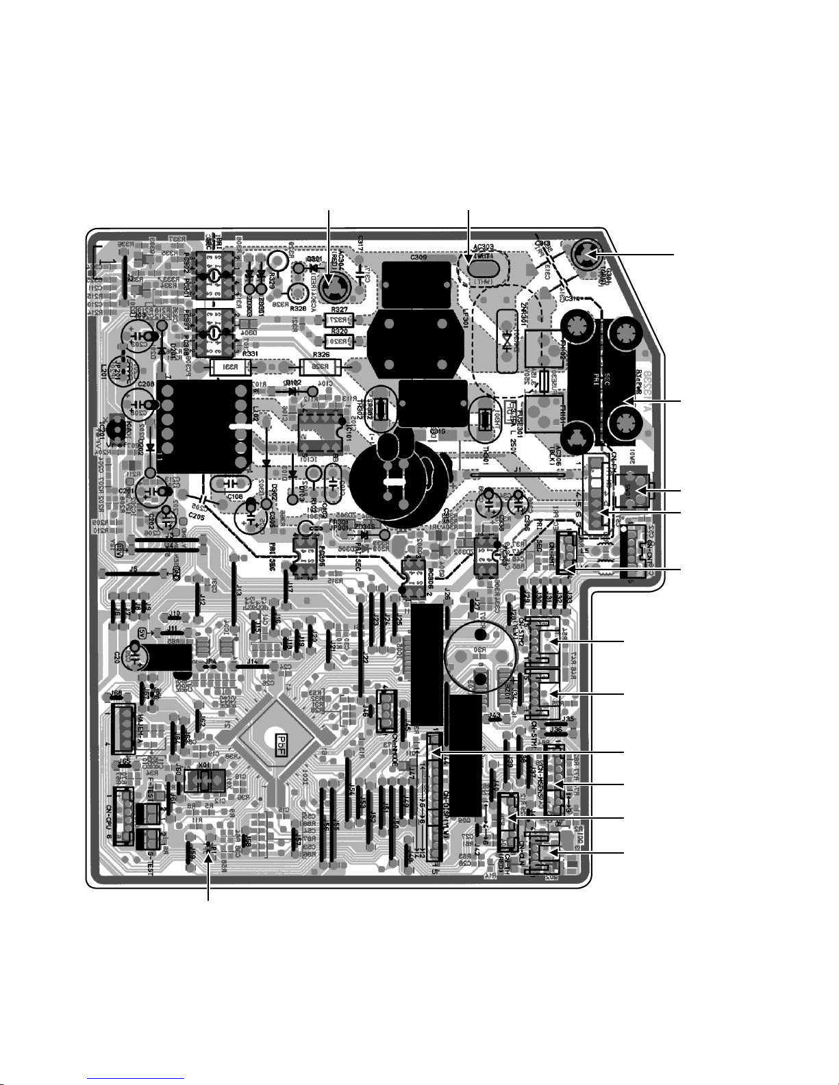
9.1.1.1 CS-S10PKH (Malaysia only) CS-S15PK CS-S18PK CS-S24PK
CN-STM2
SW01
RY-PW
R
CN-FM
G301
A
C303
A
C304
CN-RMT
CN-STM1
CN-MSENS
CN-DISP
CN-TH
CN-CLN
JP1 (Random Auto Restart enable/disable)
Page 49
49
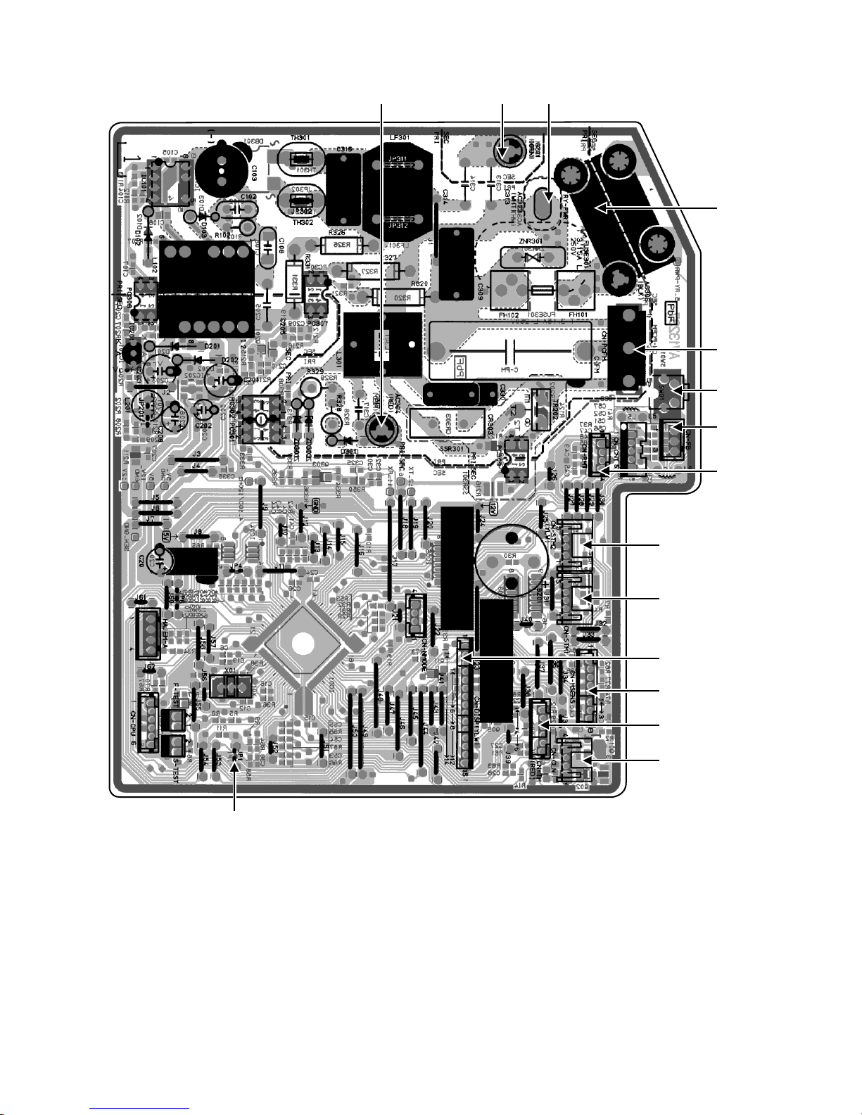
9.1.1.2 CS-S10PK (except Malaysia) CS-S13PK
CN-STM2
SW01
RY-PWR
CN-FB
CN-PCFM
A
C303
A
C304 G301
CN-RMT
CN-STM1
CN-MSENS
CN-DISP
CN-TH
CN-CLN
JP1 (Random Auto Restart enable/disable)
Page 50
50
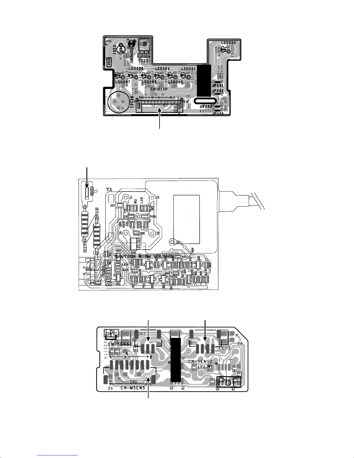
9.1.2 Indicator Printed Circuit Board
CN-DISP
9.1.3 High Voltage Power Supply Printed Circuit Board
GND
9.1.4 Comparator Printed Circuit Board
CN-SENS2CN-SENS1
CN-MSENS
Page 51
51
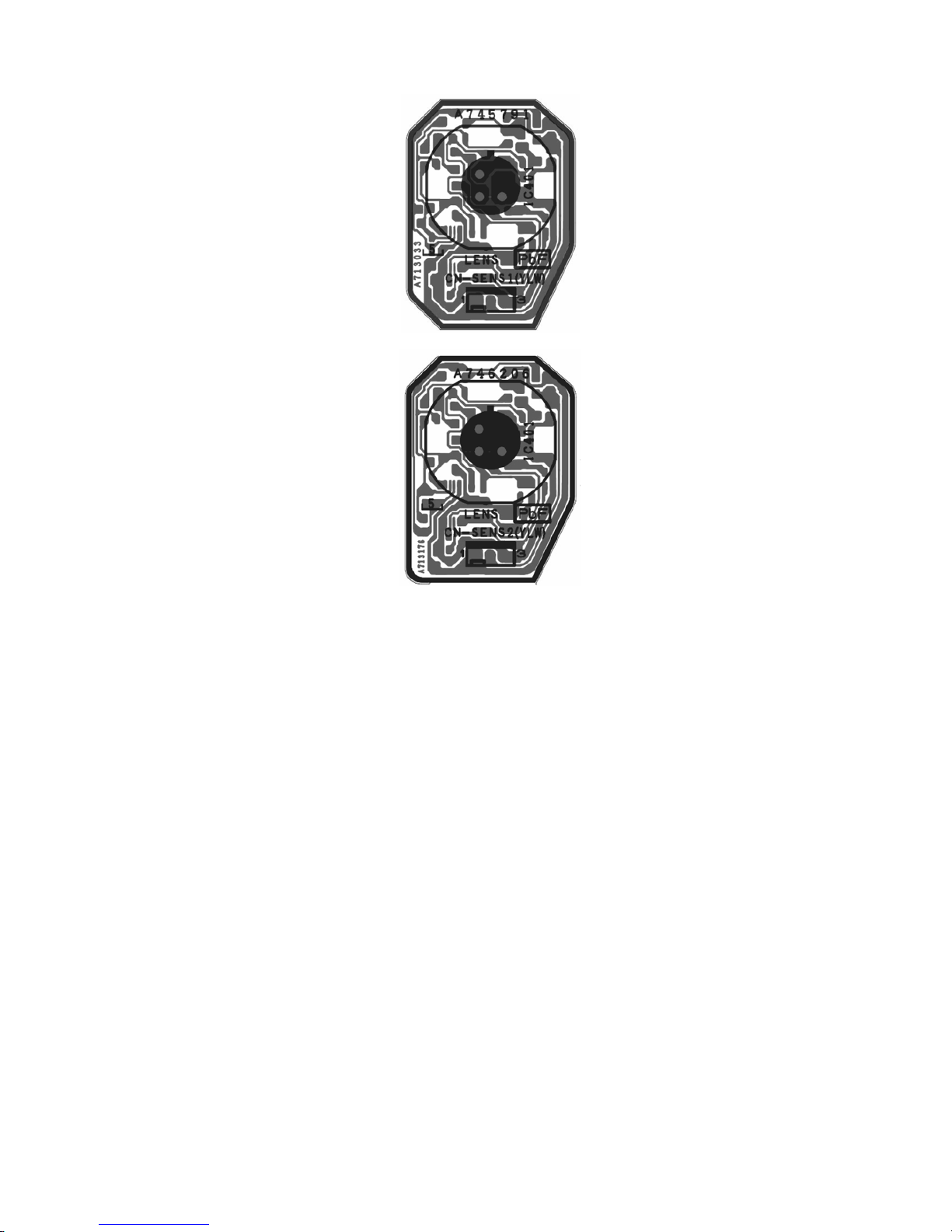
9.1.5 Human Activity Sensor Printed Circuit Board
Page 52
52
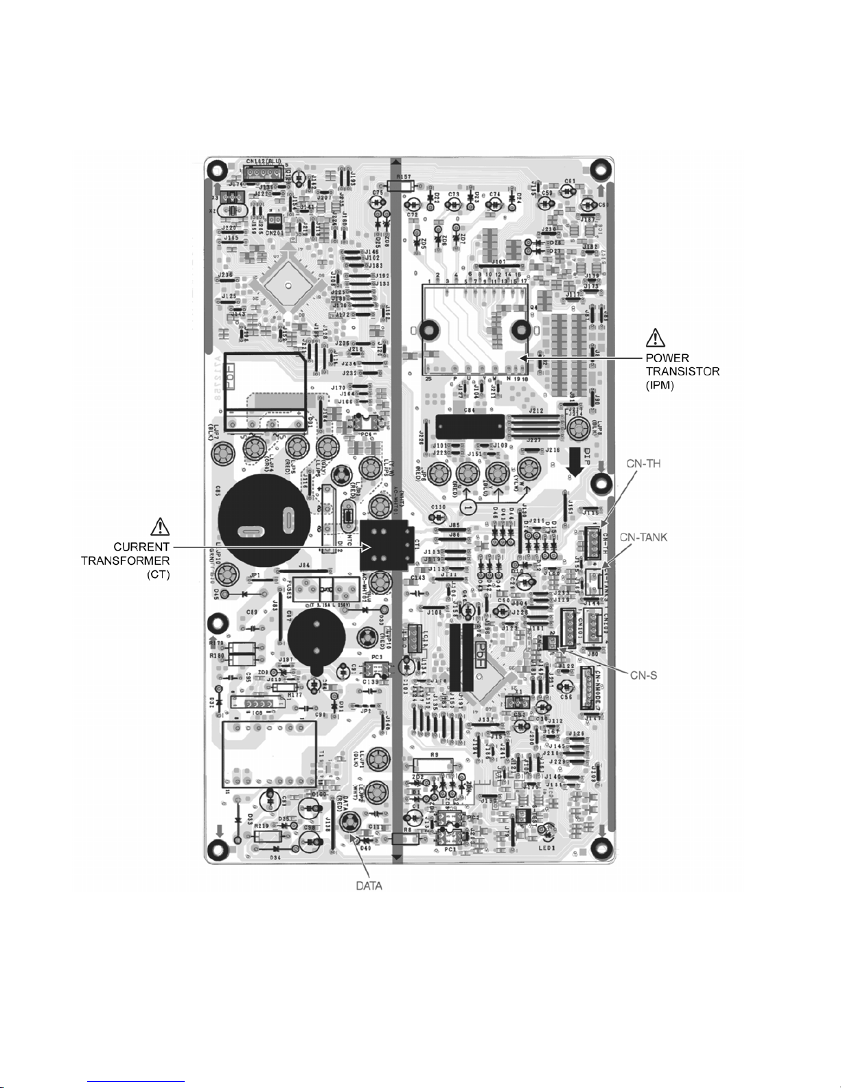
9.2 Outdoor Unit
9.2.1 Main Printed Circuit Board
9.2.1.1 CU-S10PK
Page 53
53
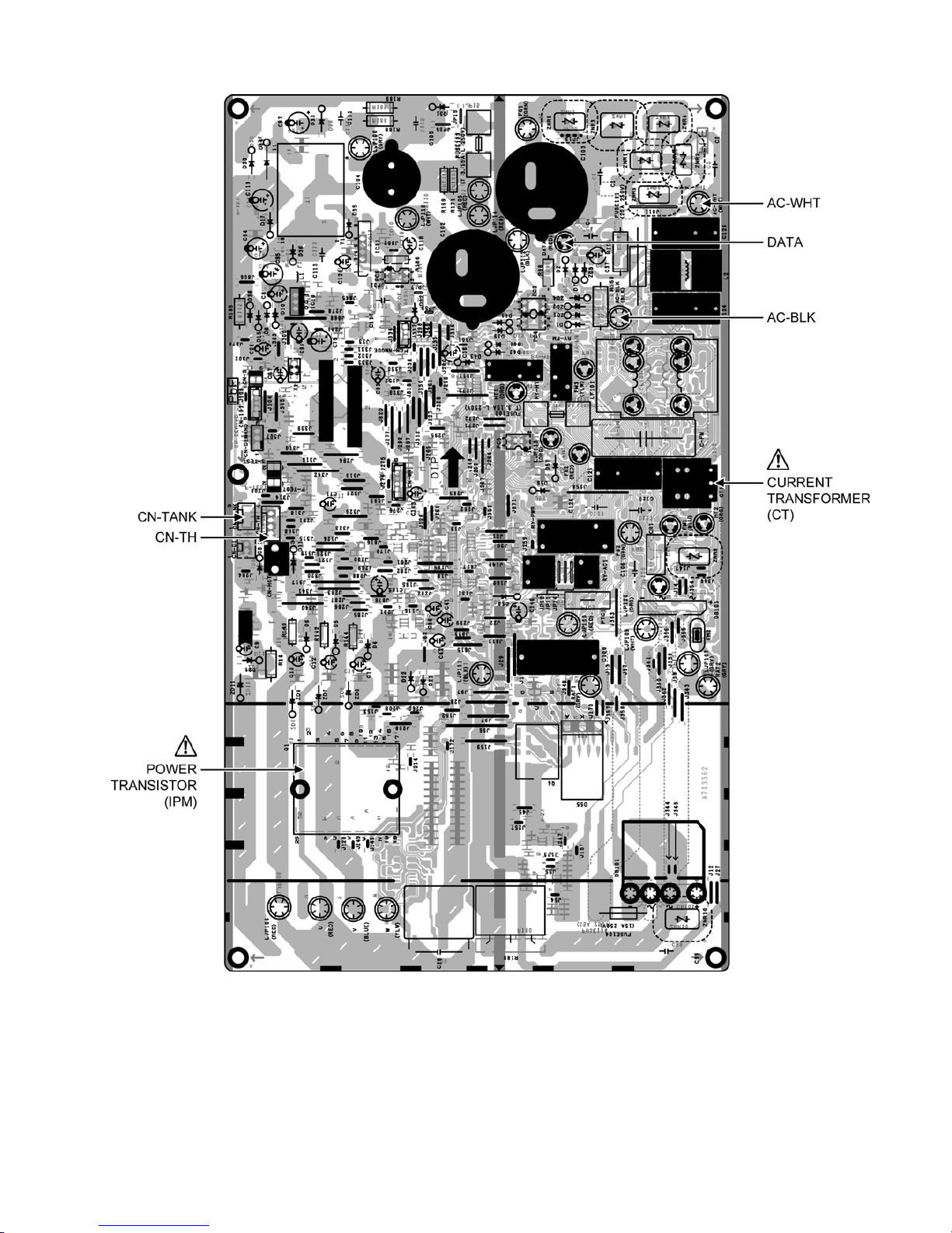
9.2.1.2 CU-S13PK CU-S15PK
Page 54
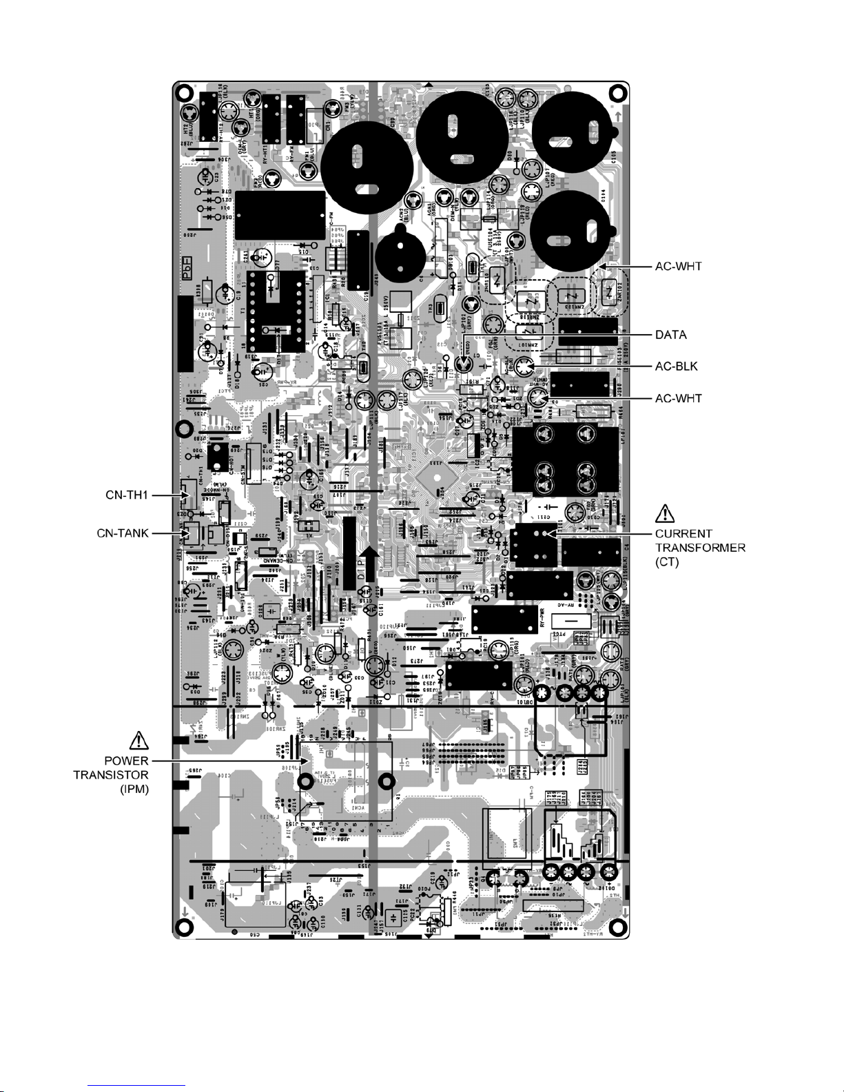
54
9.2.1.3 CU-S18PK
Page 55
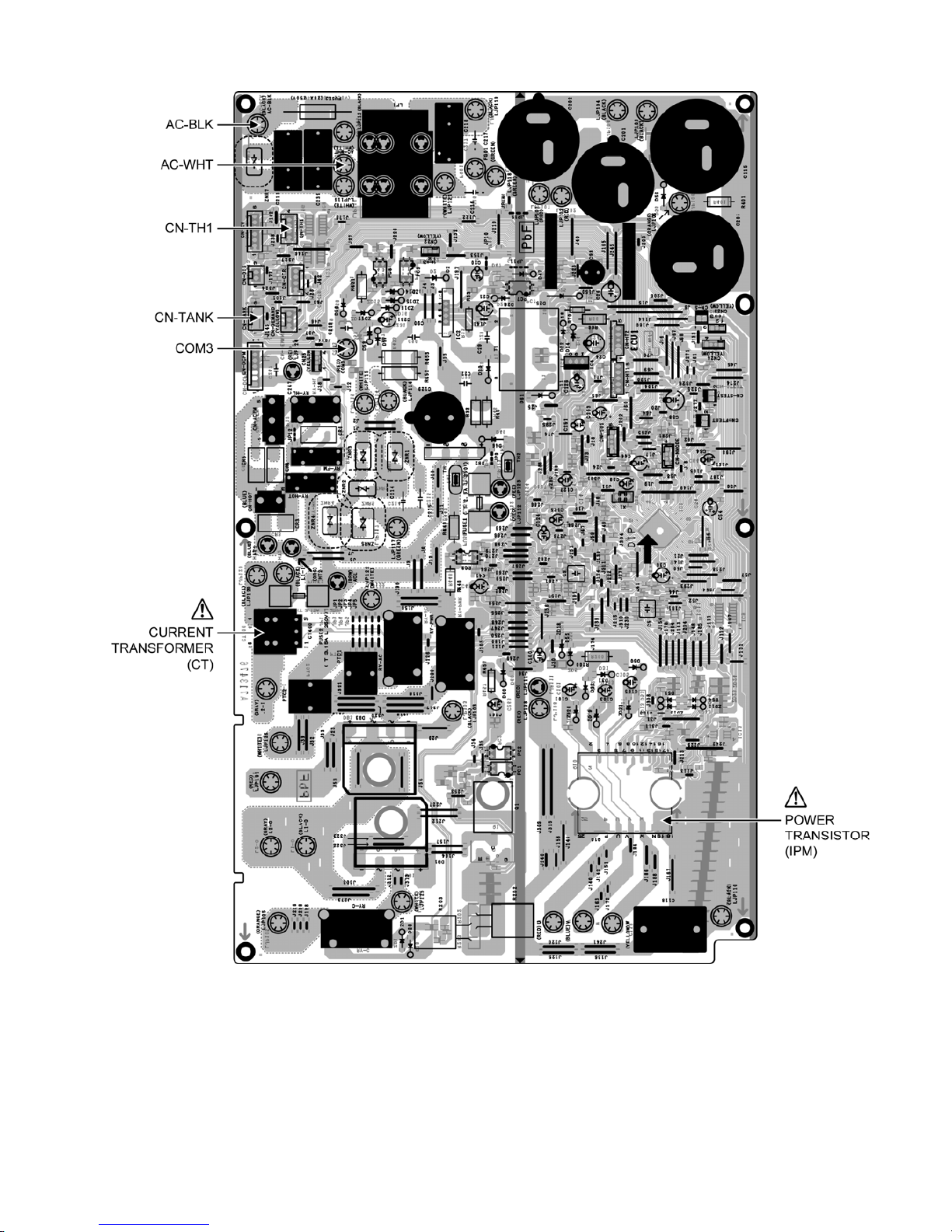
55
9.2.1.4 CU-S24PK
Page 56
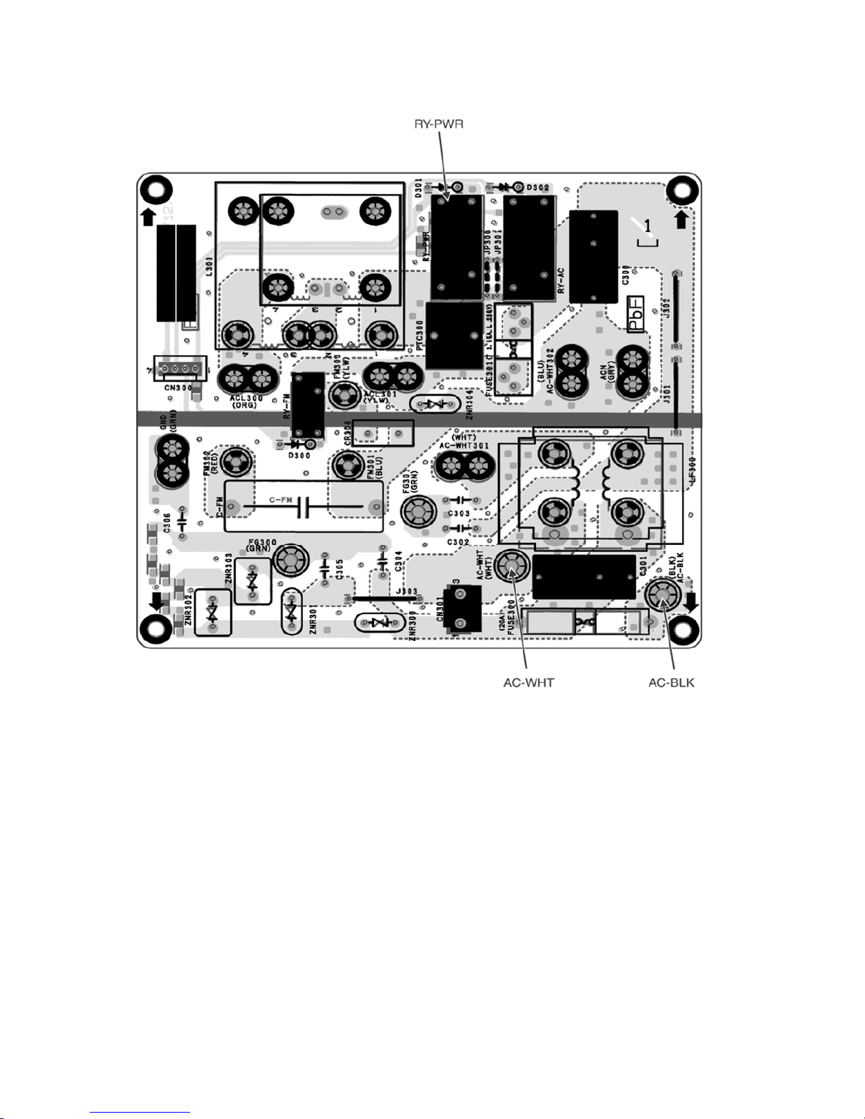
56
9.2.2 Noise Filter Printed Circuit Board
9.2.2.1 CU-S10PK
Page 57
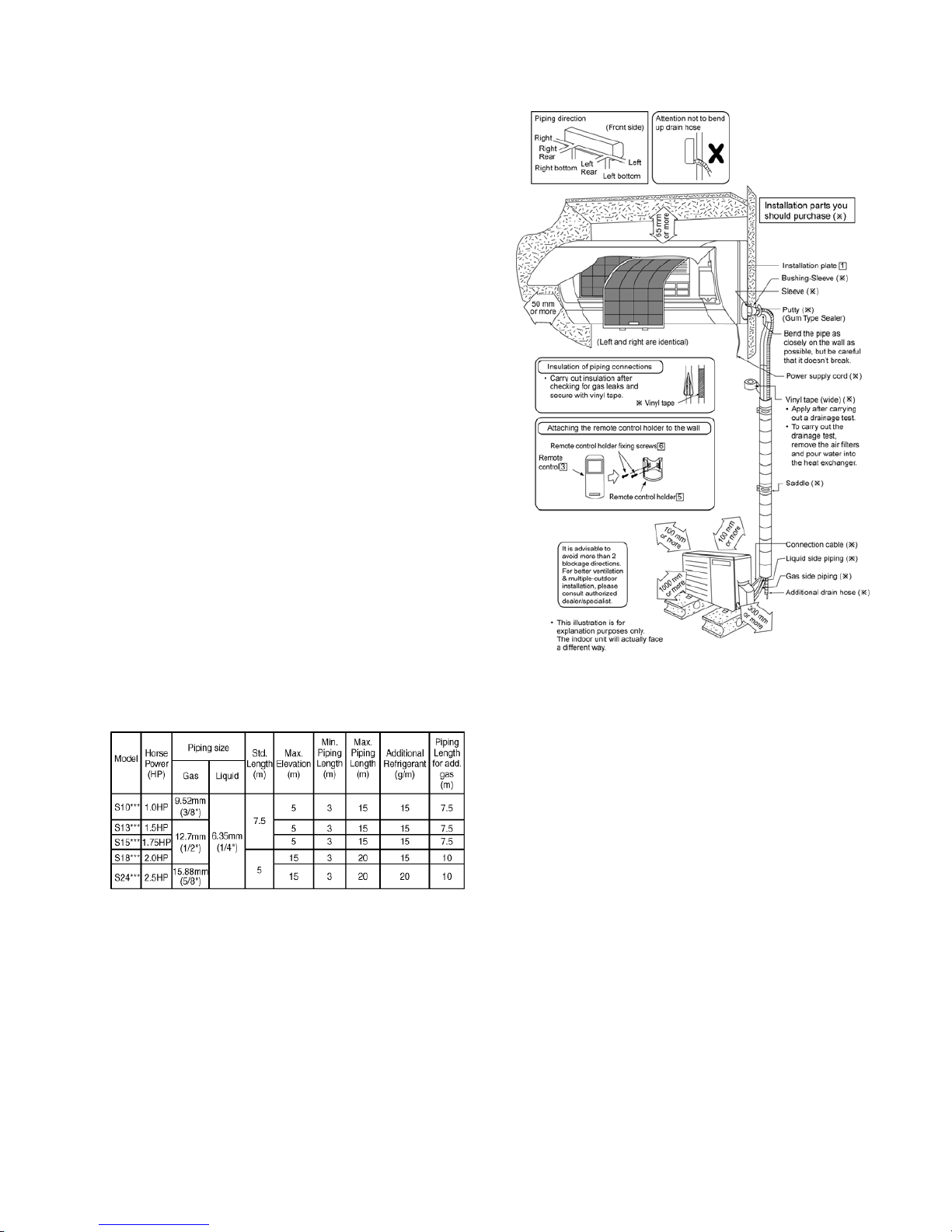
57
10. Installation Instruction
(Except Myanmar)
10.1 Select The Best Location
10.1.1 Indoor Unit
• Do not install the unit in excessive oil fume area
such as kitchen, workshop and etc.
• There should not be any heat source or steam
near the unit.
• There should not be any obstacles blocking the air
circulation.
• A place where air circulation in the room is good.
• A place where drainage can be easily done.
• A place where noise prevention is taken into
consideration.
• Do not install the unit near the door way.
• Ensure the spaces indicated by arrows from the
wall, ceiling, fence or other obstacles.
• Recommended installation height for indoor unit
shall be at least 2.5 m.
10.1.2 Outdoor Unit
• If an awning is built over the unit to prevent direct
sunlight or rain, be careful that heat radiation from
the condenser is not obstructed.
• There should not be any animal or plant which
could be affected by hot air discharged.
• Keep the spaces indicated by arrows from wall,
ceiling, fence or other obstacles.
• Do not place any obstacles which may cause a
short circuit of the discharged air.
• If piping length is over the [piping length for
additional gas], additional refrigerant should be
added as shown in the table.
Example: For S10***
If the unit is installed at 10 m distance, the quantity of
additional refrigerant should be 38 g …. (10-7.5) m ×
15 g/m =38 g.
10.1.3 Indoor/Outdoor Unit Installation
Diagram
Page 58
58
10.2 Indoor Unit
10.2.1 How to Fix Installation Plate
The mounting wall shall be strong and solid enough to prevent if from the vibration.
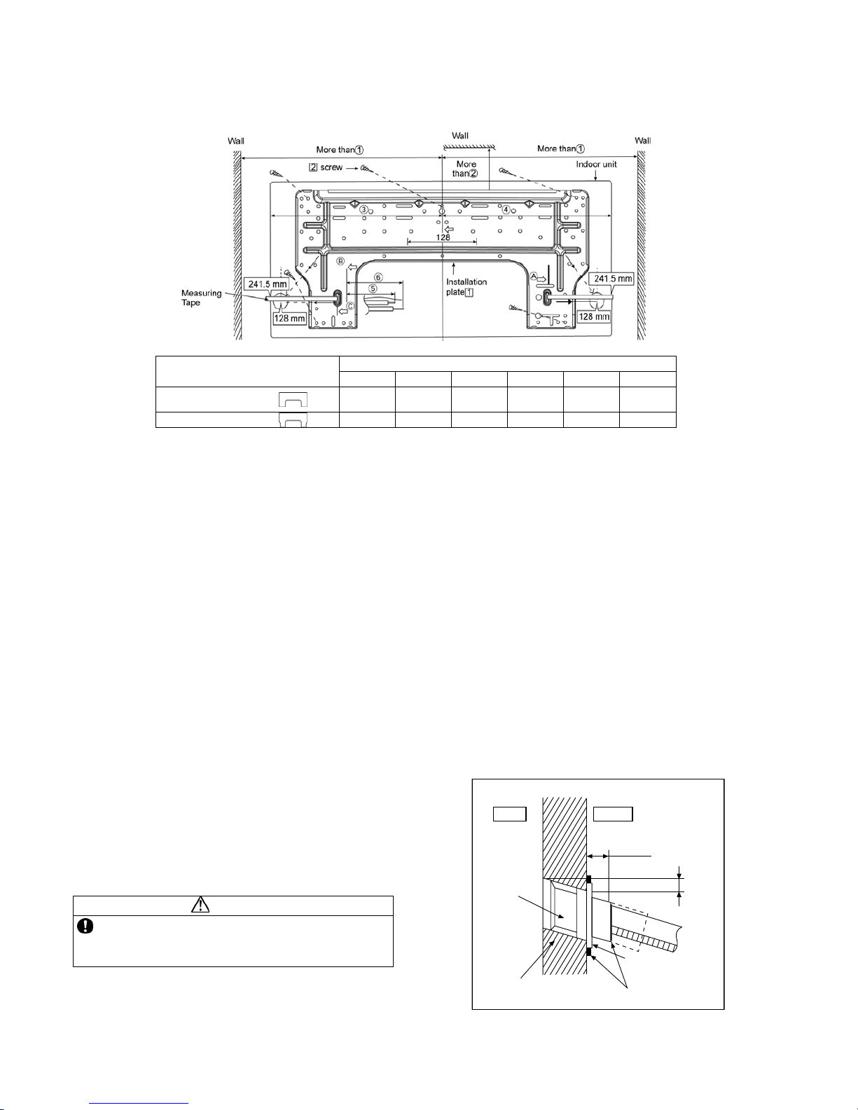
Dimension
Model
○
1
○2 ○3 ○4 ○5 ○6
S10***, S13***,
S15***
490 mm 82 mm 439 mm 432 mm 93 mm 145 mm
S18***, S24***
590 mm 82 mm 539 mm 532 mm 219 mm 269 mm
The centre of installation plate should be at more than
○
1 at right and left of the wall.
The distance from installation plate edge to ceiling should more than
○
2.
From installation plate left edge to unit’s left side is
○
3.
From installation plate right edge to unit’s right side is
○
4.
○
B : For left side piping, piping connection for liquid should be about ○5 from this line.
: For left side piping, piping connection for gas should be about
○
6 from this line.
1 Mount the installation plate on the wall with 5 screws or more (at least 5 screws).
(If mounting the unit on the concrete wall, consider using anchor bolts.)
o Always mount the installation plate horizontally by aligning the marking-off line with the thread and using
a level gauge.
2 Drill the piping plate hole with ø70 mm hole-core drill.
o Putting measuring tape at position as shown in the diagram above.
The hole center is obtained by measuring the distance namely 128 mm for left and right hole
respectively. Another method is intersection point of arrow mark extension.
The meeting point of the extension arrow mark is the hole center position.
o Drill the piping hole at either the right or the left and the hole should be slightly slanting to the outdoor
side. (refer to 10.2.2)
10.2.2 To Drill a Hole in the Wall and
Install a Sleeve of Piping
1 Insert the piping sleeve to the hole.
2 Fix the bushing to the sleeve.
3 Cut the sleeve until it extrudes about 15 mm
from the wall.
CAUTION
When the wall is hollow, please be sure to use the
sleeve for tube assembly to prevent dangers
caused by mice biting the connection cable.
4 Finish by sealing the sleeve with putty or
caulking compound at the final stage.
15 mm
Putty or caulking compound
ø70 mm through hole
Indoor
Outdoor
Sleeve
for tube
assembly
Approx. 5 - 7 mm
Bushing for tube
assembly
Wall
Page 59
59
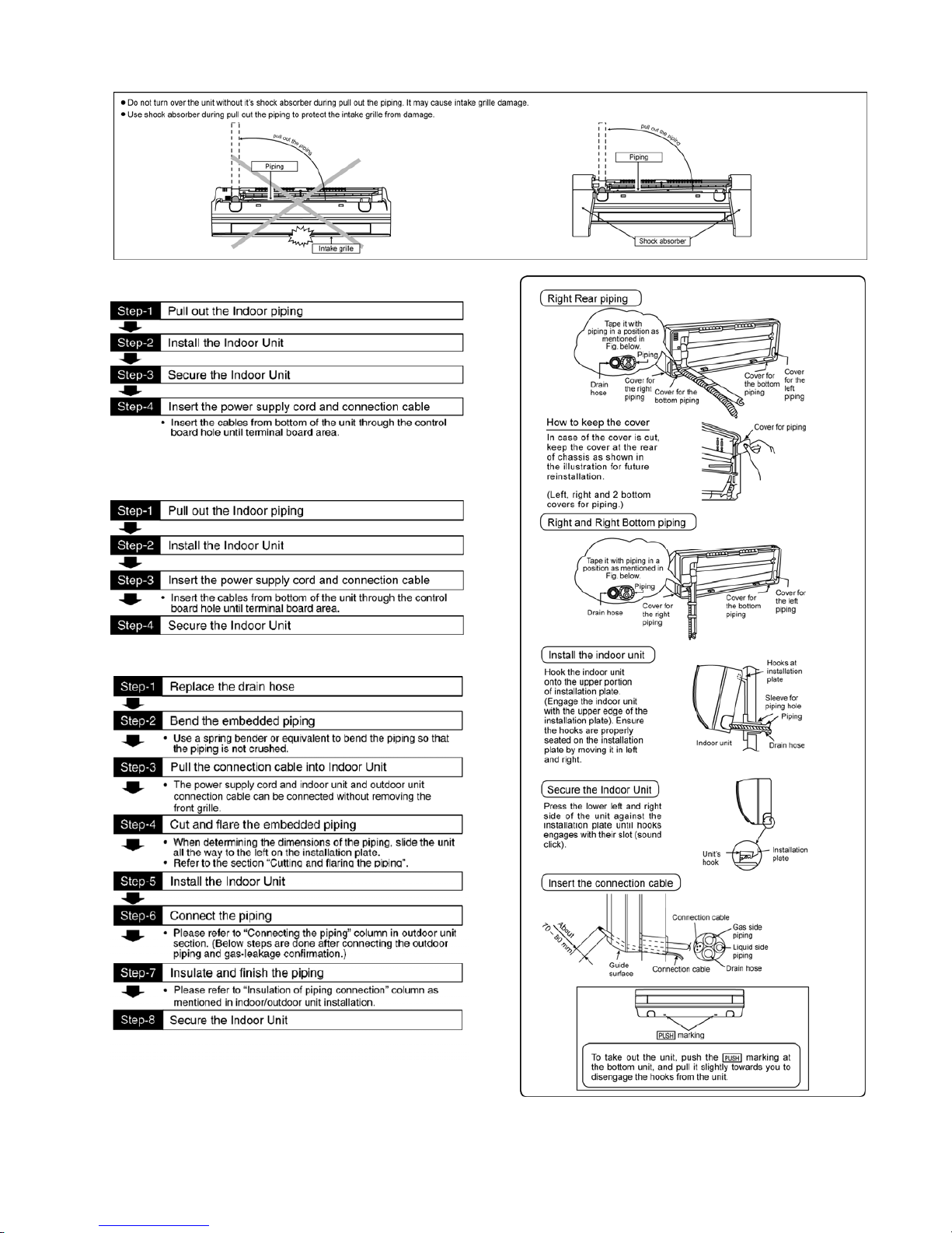
10.2.3 Indoor Unit Installation
10.2.3.1 For the right rear piping
10.2.3.2 For the right and right bottom
piping
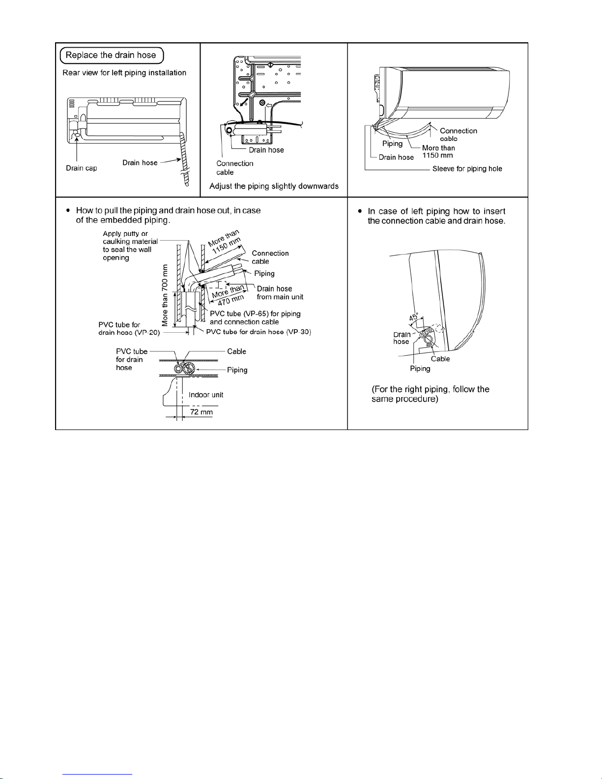
10.2.3.3 For the embedded piping
(This can be used for left rear piping and bottom
piping also.)
Page 60
60
10.2.4 Connect the Cable to the Indoor Unit
The power supply cord, indoor and outdoor unit connection cable can be connected without removing the front grille.
1 Install the indoor unit on the installing holder that mounted on the wall.
2 Open the front panel and grille door by loosening the screw.
3 Cable connection to the power supply through Isolating Devices (Disconnecting means).
o Connect the approved polychloroprene sheathed power supply cord 3 × 1.5 mm
2
(1.0 ~ 1.75HP) or
3 × 2.5 mm
2
(2.0 ~ 2.5HP), type designation 60245 IEC 57 or heavier cord to the terminal board, and
connect the other end of the cable to Isolating Devices (Disconnecting means).
o Do not use joint power supply cord. Replace the wire if the existing wire (from concealed wiring, or
otherwise) is too short.
o In unavoidable case, joining of power supply cord between isolating devices and terminal board of air
conditioner shall be done by using approved socket and plug with earth pin rated 15/16A (1.0 ~ 1.75HP
or 16A (2.0HP) or 20A (2.5HP). Wiring work to both socket and plug must follow to national wiring
standard.
4 Bind all the power supply cord lead wire with tape and route the power supply cord via the left escapement.
5 Connection cable between indoor unit and outdoor unit shall be approved polychloroprene sheathed 4 × 1.5
mm
2
(1.0 ~ 1.75HP) or 4 × 2.5 mm2 (2.0 ~ 2.5HP) flexible cord, type designation 60245 IEC 57 or heavier
cord. Do not use joint connection cable. Replace the wire if the existing wire (from concealed wiring, or
otherwise) is too short.
6 Bind all the indoor and outdoor connection cable with tape and route the connection cable via the right
escapement.
Page 61
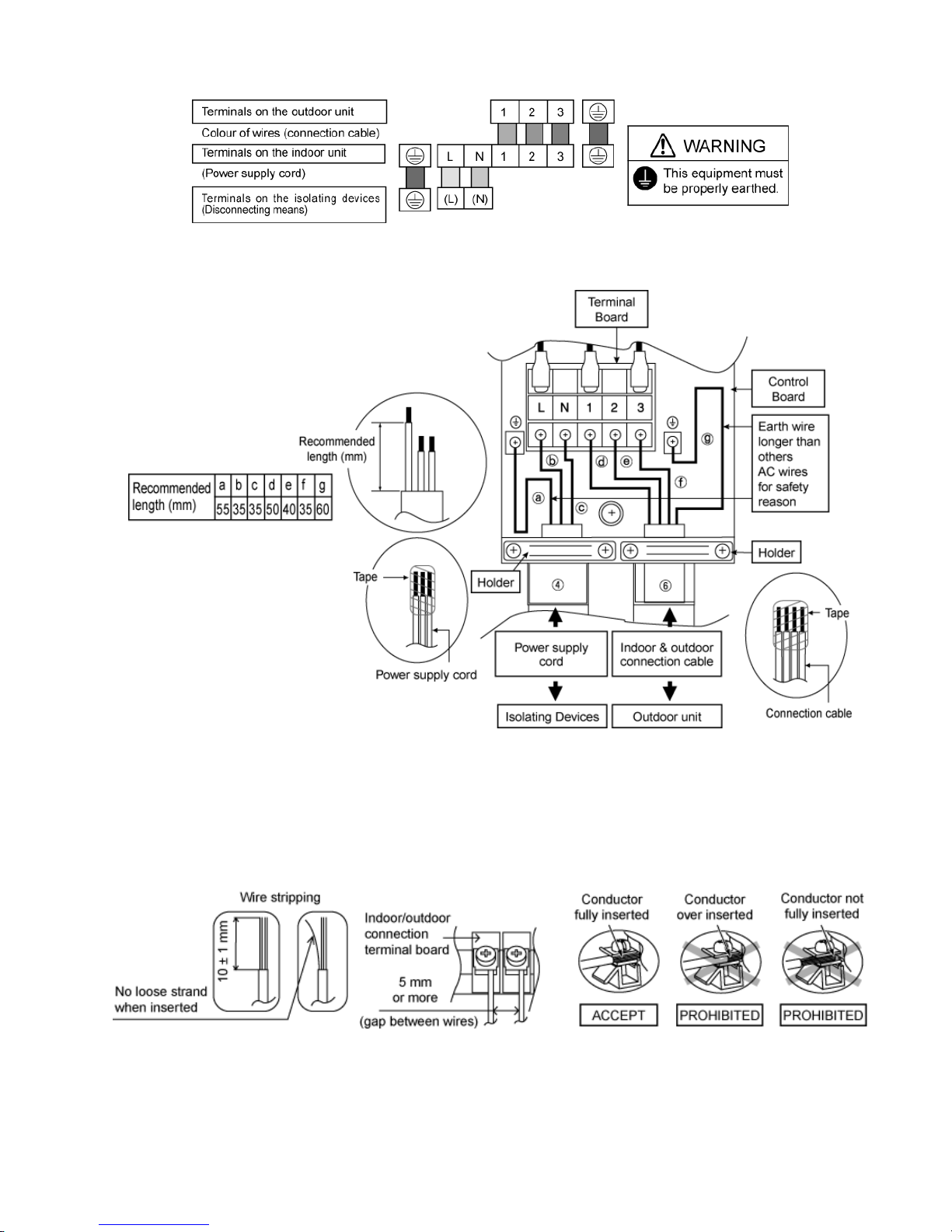
61
7 Remove the tapes and connect the power supply cord and connection cable between indoor unit and outdoor
unit according to the diagram below.
8 Secure the power supply cord and connection cable onto the control board with the holder.
9 Close grille door by tighten with screw and close the front panel.
Note:
• Isolating Devices (Disconnecting means) should have minimum 3.0 mm contact gap.
• Ensure the colour of wires of outdoor unit and the terminal Nos. are the same to the indoor’s respectively.
• Earth wire shall be Yellow/Green (Y/G) in colour and longer than other AC wires as shown in the figure for the
electrical safety in case of the slipping out of the cord from the anchorage.
10.2.4.1 Wire Stripping, Connecting Requirement
Page 62
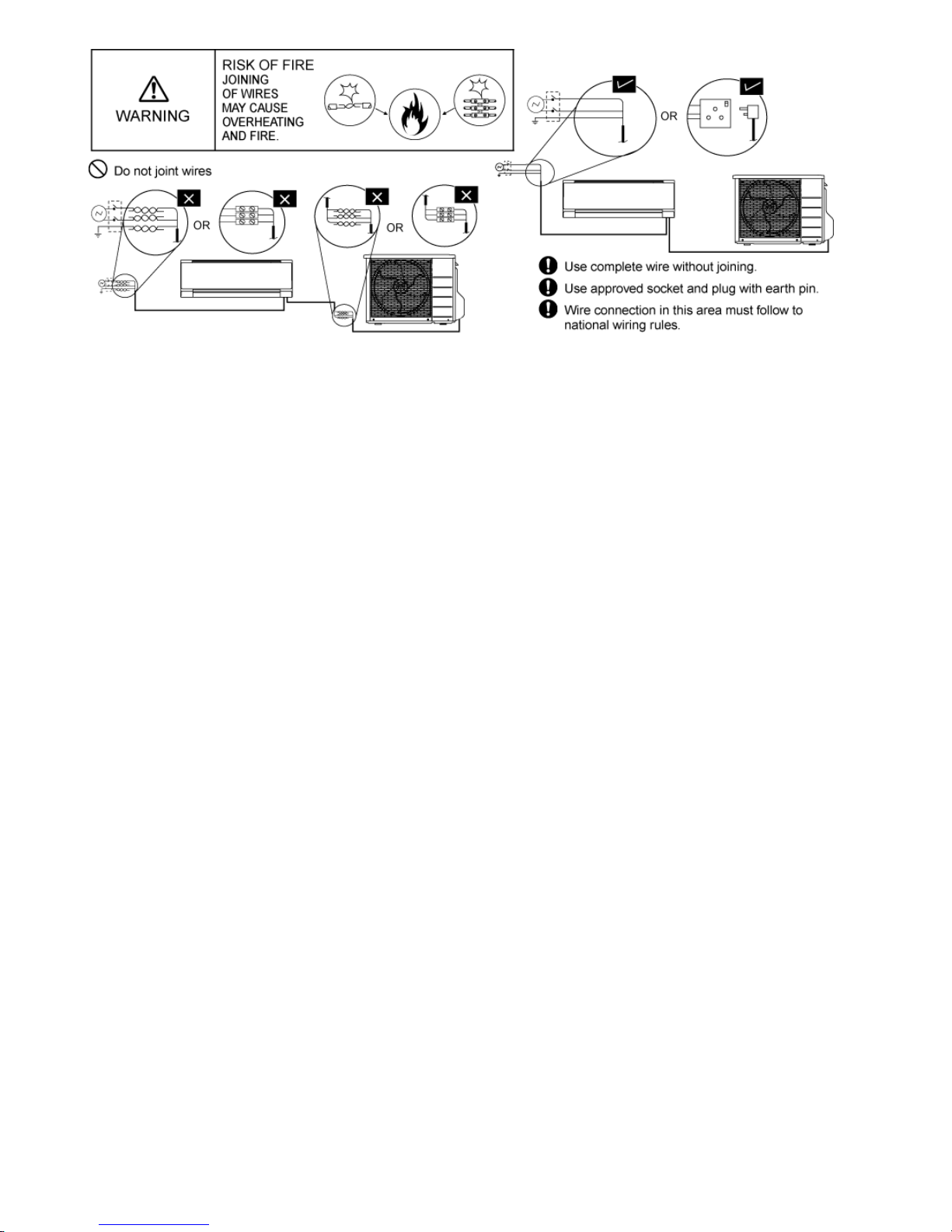
62
Page 63
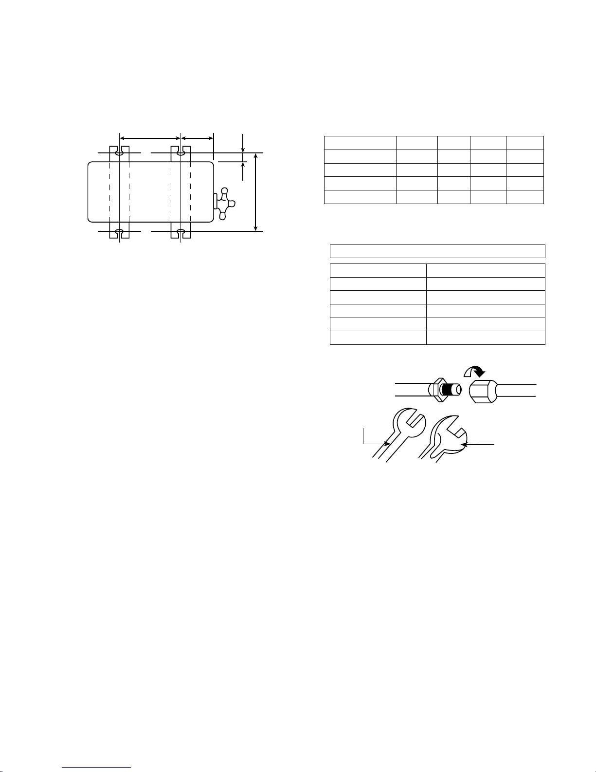
63
10.3 Outdoor Unit
10.3.1 Install the Outdoor Unit
• After selecting the best location, start installation to Indoor/Outdoor Unit Installation Diagram.
1 Fix the unit on concrete or rigid frame firmly and horizontally by bolt nut (ø10 mm).
2 When installing at roof, please consider strong wind and earthquake.
3 Please fasten the installation stand firmly with bolt or nails.
AB
C
D
Model A B C D
S10*** 474 mm 87 mm 18.5 mm 261 mm
S13***, S15*** 570 mm 105 mm 18.5 mm 261 mm
S18*** 540 mm 160 mm 18.5 mm 330 mm
S24*** 613 mm 131 mm 16 mm 360.5 mm
10.3.2 Connect the Piping
10.3.2.1 Connecting the piping to Indoor
Please make flare after inserting flare nut
(locate at joint portion of tube assembly) onto the
copper pipe. (In case of using long piping)
Connect the piping
• Align the center of piping and sufficiently tighten the
flare nut with fingers.
• Further tighten the flare nut with torque wrench in
specified torque as stated in the table.
10.3.2.2 Connecting the piping to Outdoor
Decide piping length and then cut by using pipe cutter.
Remove burrs from cut edge.
Make flare after inserting the flare nut (locate at valve)
onto the copper pipe.
Align center of piping to valve and then tighten with
torque wrench to the specified torque as stated in the
table.
To rq u e
wrench
Spanner
or Wrench
Do not overtighten, overtightening may cause gas leakage.
Piping size Torque
6.35 mm (1/4”) [18 N•m (1.8 kgf.m)]
9.52 mm (3/8”) [42 N•m (4.3 kgf.m)]
12.7 mm (1/2”) [55 N•m (5.6 kgf.m)]
15.88 mm (5/8”) [65 N•m (6.6 kgf.m)]
19.05 mm (3/4”) [100 N•m (10.2 kgf.m)]
Page 64
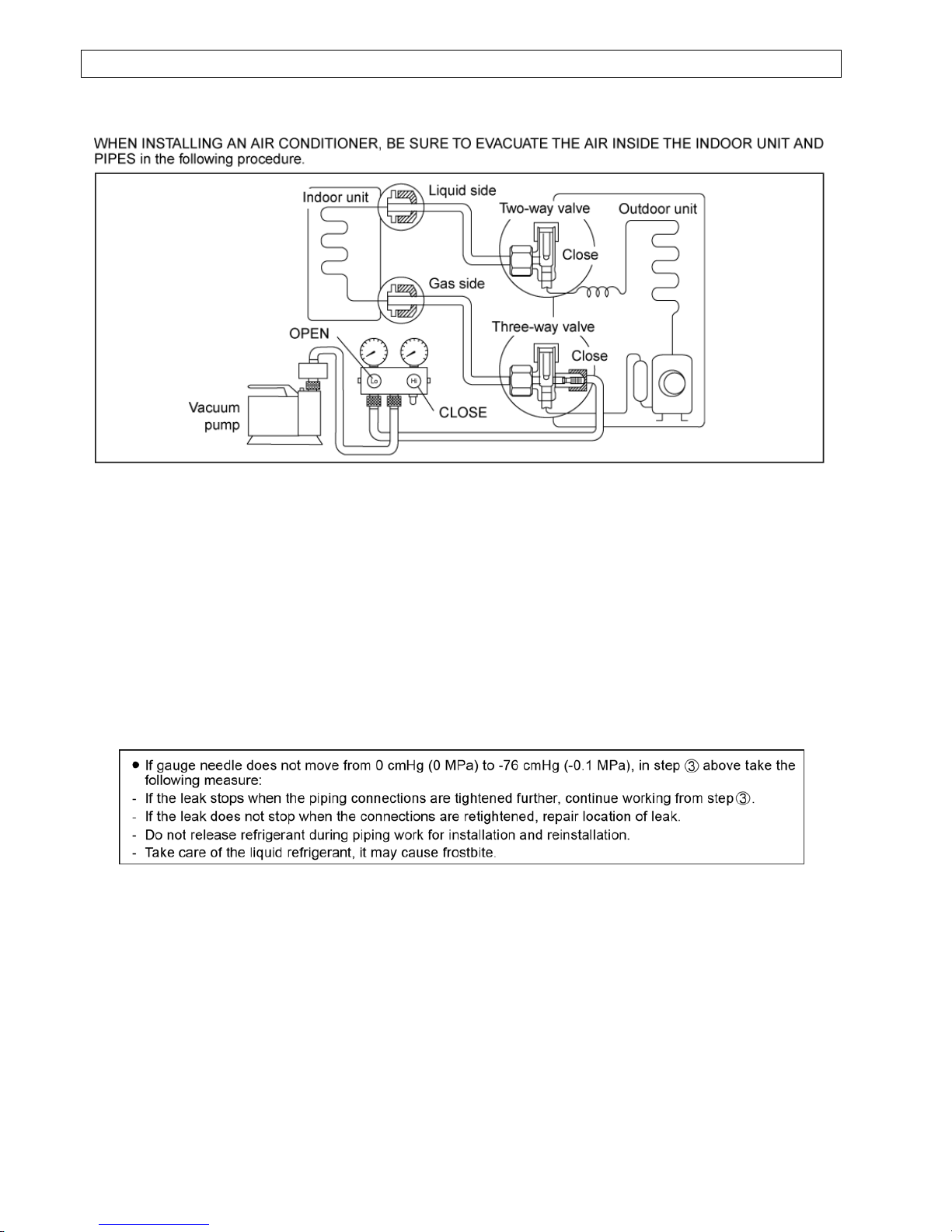
64
AIR PURGING METHOD IS PROHIBITED FOR R410A SYSTEM
10.3.3 Evacuation of the Equipment
1 Connect a charging hose with a push pin to the Low side of a charging set and the service port of the 3-way
valve.
o Be sure to connect the end of the charging hose with the push pin to the service port.
2 Connect the center hose of the charging set to a vacuum pump.
3 Turn on the power switch of the vacuum pump and make sure that the needle in the gauge moves from
0 cmHg (0 MPa) to -76 cmHg (-0.1 MPa). Then evacuate the air approximately ten minutes.
4 Close the Low side valve of the charging set and turn off the vacuum pump. Make sure that the needle in the
gauge does not move after approximately five minutes.
Note: BE SURE TO TAKE THIS PROCEDURE IN ORDER TO AVOID REFRIGERENT GAS LEAKAGE.
5 Disconnect the charging hose from the vacuum pump and from the service port of the 3-way valve.
6 Tighten the service port caps of the 3-way valve at a torque of 18 N•m with a torque wrench.
7 Remove the valve caps of both of the 2-way valve and 3-way valve. Position both of the valves to “OPEN”
using a hexagonal wrench (4 mm).
8 Mount valve caps onto the 2-way valve and the 3-way valve.
o Be sure to check for gas leakage.
Page 65
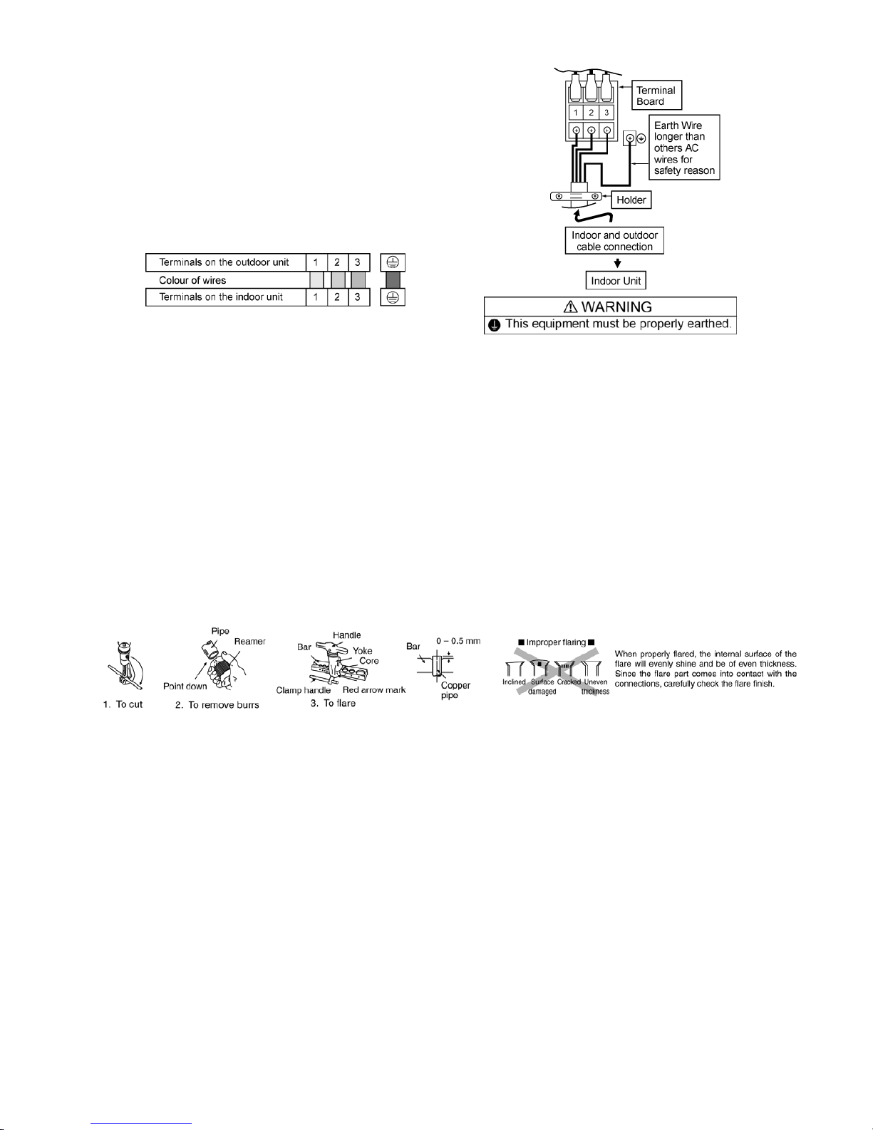
65
10.3.4 Connect the cable to the Outdoor Unit
1 Remove the control board cover from the unit
by loosening the screw.
2 Connection cable between indoor unit and
outdoor unit shall be approved
polychloroprene sheathed 4 × 1.5 mm
2
(1.0 ~
1.75HP) or 4 × 2.5 mm
2
(2.0 ~ 2.5HP) flexible
cord, type designation 60245 IEC 57 or
heavier cord. Do not use joint connection
cable. Replace the wire if the existing wire
(from concealed wiring, or otherwise) is too
short.
3 Secure the cable onto the control board with
the holder (clamper).
4 Attach the control board cover back to the
original position with screw.
5 For wire stripping and connection requirement,
refer to instruction g of indoor unit.
• Earth wire shall be Yellow/Green (Y/G) in colour
and longer than other AC wires for safety
reason.
10.3.5 Piping Insulation
1 Please carry out insulation at pipe connection portion as mentioned in Indoor/Outdoor Unit Installation
Diagram. Please wrap the insulated piping end to prevent water from going inside the piping.
2 If drain hose or connecting piping is in the room (where dew may form), please increase the insulation by
using POLY-E FOAM with thickness 6 mm or above.
10.3.5.1 Cutting and flaring the piping
1 Please cut using pipe cutter and then remove the burrs.
2 Remove the burrs by using reamer. If burrs is not removed, gas leakage may be caused. Turn the piping end
down to avoid the metal powder entering the pipe.
3 Please make flare after inserting the flare nut onto the copper pipes.
Page 66
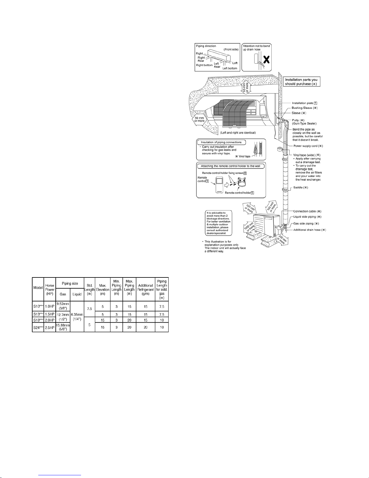
66
11. Installation Instruction
(For Myanmar only)
11.1 Select The Best Location
11.1.1 Indoor Unit
• Do not install the unit in excessive oil fume area
such as kitchen, workshop and etc.
• There should not be any heat source or steam
near the unit.
• There should not be any obstacles blocking the air
circulation.
• A place where air circulation in the room is good.
• A place where drainage can be easily done.
• A place where noise prevention is taken into
consideration.
• Do not install the unit near the door way.
• Ensure the spaces indicated by arrows from the
wall, ceiling, fence or other obstacles.
• Recommended installation height for indoor unit
shall be at least 2.5 m.
11.1.2 Outdoor Unit
• If an awning is built over the unit to prevent direct
sunlight or rain, be careful that heat radiation from
the condenser is not obstructed.
• There should not be any animal or plant which
could be affected by hot air discharged.
• Keep the spaces indicated by arrows from wall,
ceiling, fence or other obstacles.
• Do not place any obstacles which may cause a
short circuit of the discharged air.
• If piping length is over the [piping length for
additional gas], additional refrigerant should be
added as shown in the table.
Example: For S10***
If the unit is installed at 10 m distance, the quantity of
additional refrigerant should be 38 g …. (10-7.5) m ×
15 g/m =38 g.
11.1.3 Indoor/Outdoor Unit Installation
Diagram
Page 67
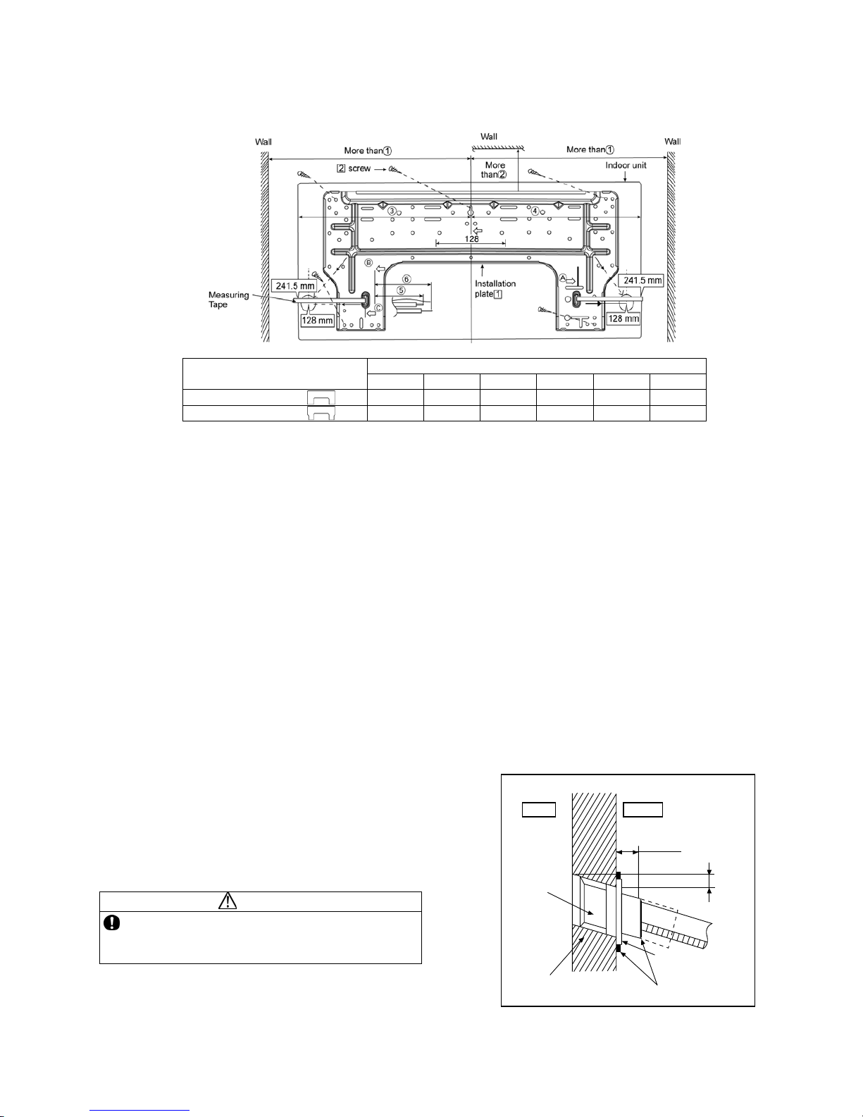
67
11.2 Indoor Unit
11.2.1 How to Fix Installation Plate
The mounting wall shall be strong and solid enough to prevent if from the vibration.
Dimension
Model
○
1
○2 ○3 ○4 ○5 ○6
S10***, S13***
490 mm 82 mm 439 mm 432 mm 93 mm 145 mm
S18***, S24***
590 mm 82 mm 539 mm 532 mm 219 mm 269 mm
The centre of installation plate should be at more than
○
1 at right and left of the wall.
The distance from installation plate edge to ceiling should more than
○
2.
From installation plate left edge to unit’s left side is
○
3.
From installation plate right edge to unit’s right side is
○
4.
○
B : For left side piping, piping connection for liquid should be about ○5 from this line.
: For left side piping, piping connection for gas should be about
○
6 from this line.
3 Mount the installation plate on the wall with 5 screws or more (at least 5 screws).
(If mounting the unit on the concrete wall, consider using anchor bolts.)
o Always mount the installation plate horizontally by aligning the marking-off line with the thread and using
a level gauge.
4 Drill the piping plate hole with ø70 mm hole-core drill.
o Putting measuring tape at position as shown in the diagram above.
The hole center is obtained by measuring the distance namely 128 mm for left and right hole
respectively. Another method is intersection point of arrow mark extension.
The meeting point of the extension arrow mark is the hole center position.
o Drill the piping hole at either the right or the left and the hole should be slightly slanting to the outdoor
side. (refer to 11.2.2)
11.2.2 To Drill a Hole in the Wall and
Install a Sleeve of Piping
5 Insert the piping sleeve to the hole.
6 Fix the bushing to the sleeve.
7 Cut the sleeve until it extrudes about 15 mm
from the wall.
CAUTION
When the wall is hollow, please be sure to use the
sleeve for tube assembly to prevent dangers
caused by mice biting the connection cable.
8 Finish by sealing the sleeve with putty or
caulking compound at the final stage.
15 mm
Putty or caulking compound
ø70 mm through hole
Indoor
Outdoor
Sleeve
for tube
assembly
Approx. 5 - 7 mm
Bushing for tube
assembly
Wall
Page 68
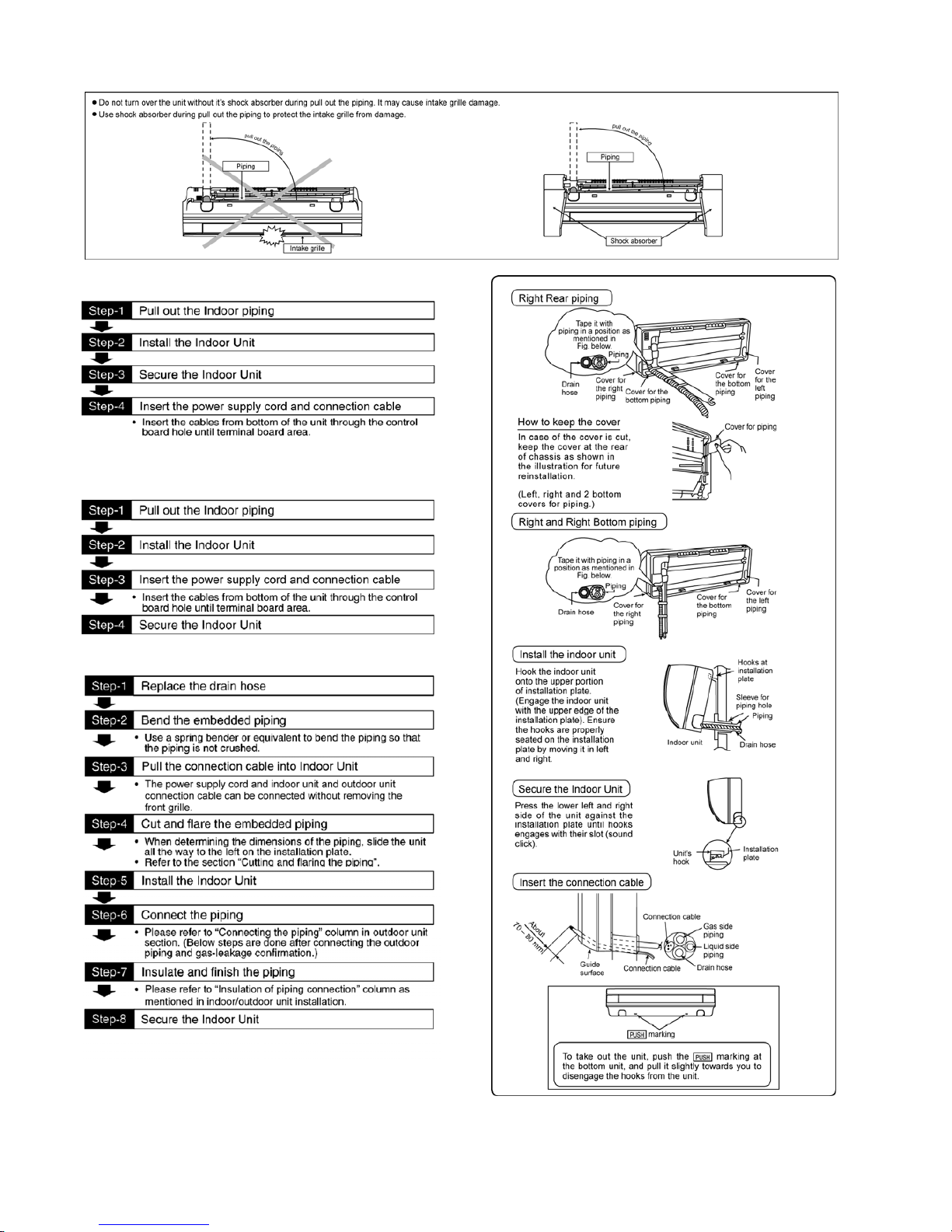
68
11.2.3 Indoor Unit Installation
11.2.3.1 For the right rear piping
11.2.3.2 For the right and right bottom
piping
11.2.3.3 For the embedded piping
(This can be used for left rear piping and bottom
piping also.)
Page 69
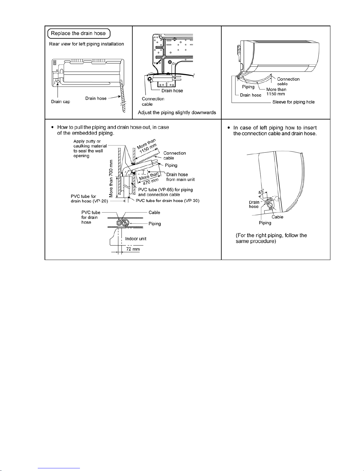
69
11.2.4 Connect the Cable to the Indoor Unit
The power supply cord, indoor and outdoor unit connection cable can be connected without removing the front grille.
4 Install the indoor unit on the installing holder that mounted on the wall.
5 Open the front panel and grille door by loosening the screw.
6 Cable connection to the power supply through Isolating Devices (Disconnecting means).
o Connect the approved polychloroprene sheathed power supply cord 3 × 1.5 mm
2
(1.0 ~ 1.5HP) or
3 × 2.5 mm
2
(2.0 ~ 2.5HP), type designation 60245 IEC 57 or heavier cord to the terminal board, and
connect the other end of the cable to Isolating Devices (Disconnecting means).
o Do not use joint power supply cord. Replace the wire if the existing wire (from concealed wiring, or
otherwise) is too short.
o In unavoidable case, joining of power supply cord between isolating devices and terminal board of air
conditioner shall be done by using approved socket and plug with earth pin rated 15/16A (1.0 ~ 1.5HP or
16A (2.0HP) or 20A (2.5HP). Wiring work to both socket and plug must follow to national wiring standard.
7 Bind all the power supply cord lead wire with tape and route the power supply cord via the left escapement.
8 Connection cable between indoor unit and outdoor unit shall be approved polychloroprene sheathed 4 × 1.5
mm
2
(1.0 ~ 1.5HP) or 4 × 2.5 mm2 (2.0 ~ 2.5HP) flexible cord, type designation 60245 IEC 57 or heavier cord.
Do not use joint connection cable. Replace the wire if the existing wire (from concealed wiring, or otherwise)
is too short.
9 Bind all the indoor and outdoor connection cable with tape and route the connection cable via the right
escapement.
Page 70
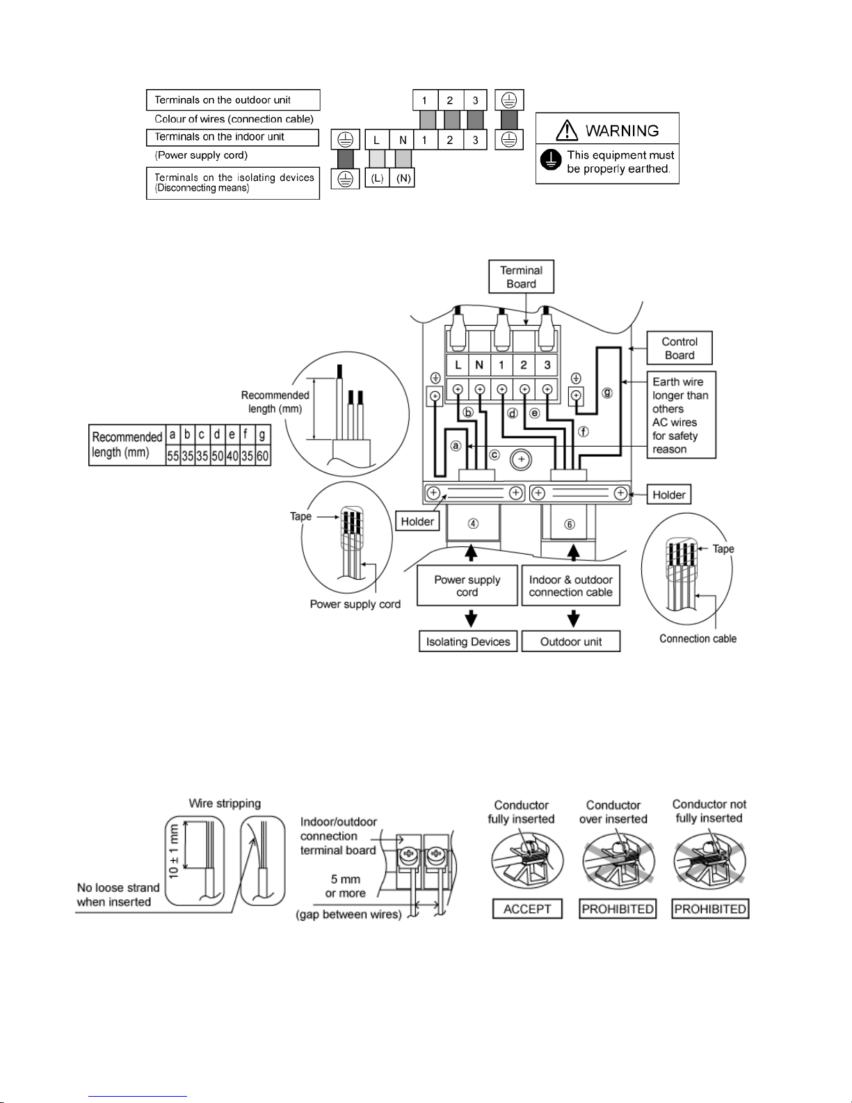
70
10 Remove the tapes and connect the power supply cord and connection cable between indoor unit and outdoor
unit according to the diagram below.
11 Secure the power supply cord and connection cable onto the control board with the holder.
12 Close grille door by tighten with screw and close the front panel.
Note:
• Isolating Devices (Disconnecting means) should have minimum 3.0 mm contact gap.
• Ensure the colour of wires of outdoor unit and the terminal Nos. are the same to the indoor’s respectively.
• Earth wire shall be Yellow/Green (Y/G) in colour and longer than other AC wires as shown in the figure for the
electrical safety in case of the slipping out of the cord from the anchorage.
11.2.4.1 Wire Stripping, Connecting Requirement
Page 71
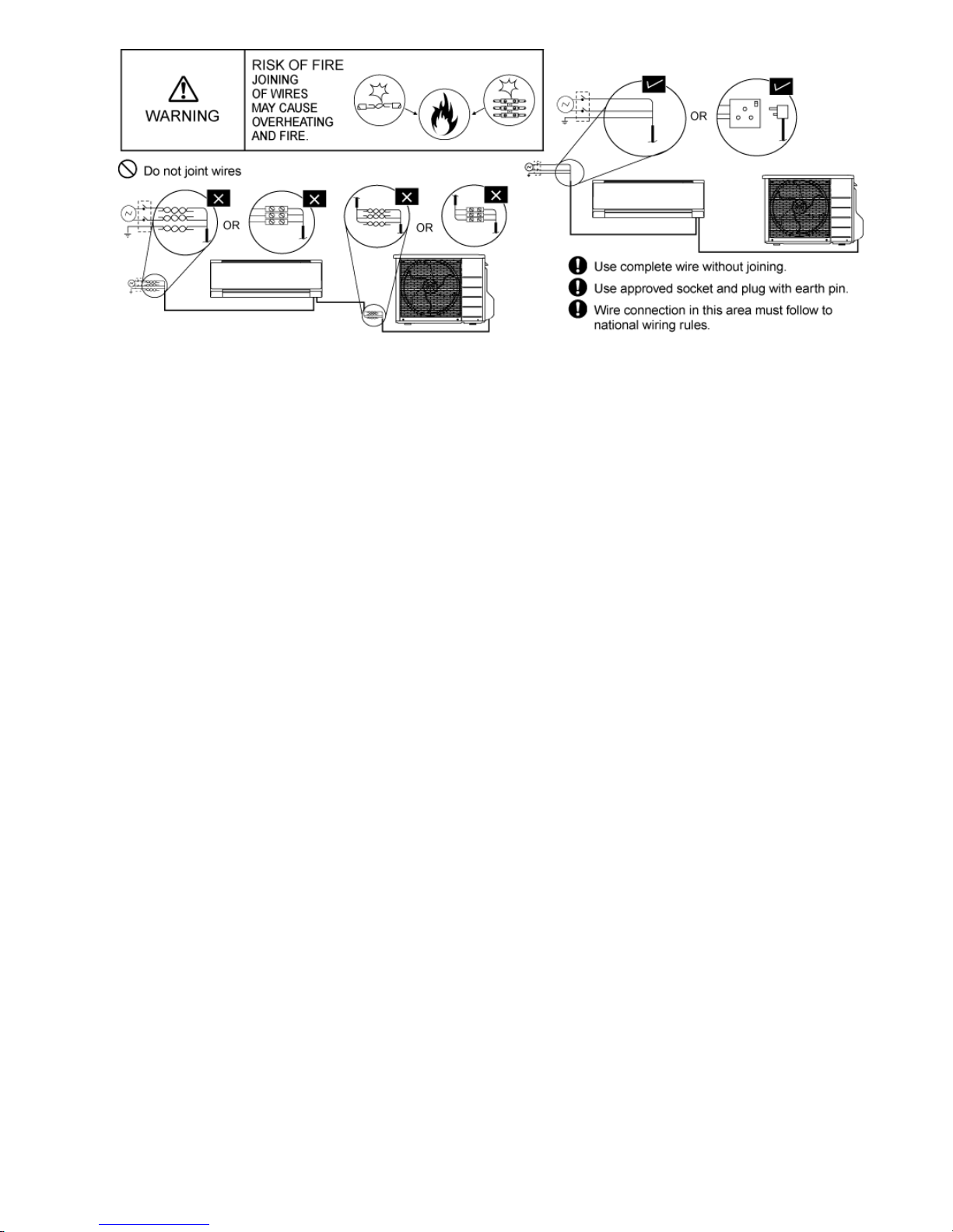
71
Page 72
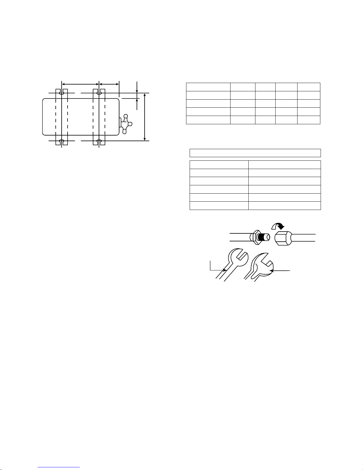
72
11.3 Outdoor Unit
11.3.1 Install the Outdoor Unit
• After selecting the best location, start installation to Indoor/Outdoor Unit Installation Diagram.
1 Fix the unit on concrete or rigid frame firmly and horizontally by bolt nut (ø10 mm).
2 When installing at roof, please consider strong wind and earthquake.
3 Please fasten the installation stand firmly with bolt or nails.
AB
C
D
Model A B C D
S10*** 474 mm 87 mm 18.5 mm 261 mm
S13*** 570 mm 105 mm 18.5 mm 261 mm
S18*** 540 mm 160 mm 18.5 mm 330 mm
S24*** 613 mm 131 mm 16 mm 360.5 mm
11.3.2 Connect the Piping
11.3.2.1 Connecting the piping to Indoor
Please make flare after inserting flare nut
(locate at joint portion of tube assembly) onto the
copper pipe. (In case of using long piping)
Connect the piping
• Align the center of piping and sufficiently tighten the
flare nut with fingers.
• Further tighten the flare nut with torque wrench in
specified torque as stated in the table.
11.3.2.2 Connecting the piping to Outdoor
Decide piping length and then cut by using pipe cutter.
Remove burrs from cut edge.
Make flare after inserting the flare nut (locate at valve)
onto the copper pipe.
Align center of piping to valve and then tighten with
torque wrench to the specified torque as stated in the
table.
To rq u e
wrench
Spanner
or Wrench
Do not overtighten, overtightening may cause gas leakage.
Piping size Torque
6.35 mm (1/4”) [18 N•m (1.8 kgf.m)]
9.52 mm (3/8”) [42 N•m (4.3 kgf.m)]
12.7 mm (1/2”) [55 N•m (5.6 kgf.m)]
15.88 mm (5/8”) [65 N•m (6.6 kgf.m)]
19.05 mm (3/4”) [100 N•m (10.2 kgf.m)]
Page 73
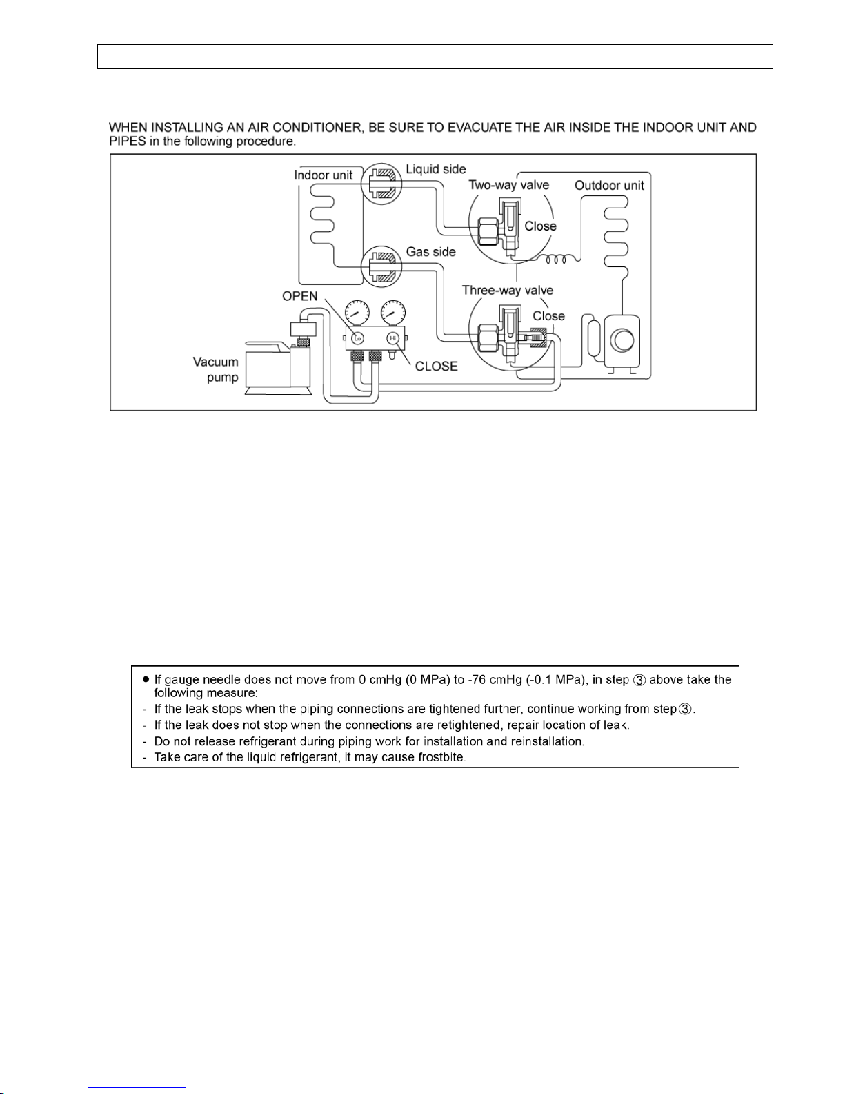
73
AIR PURGING METHOD IS PROHIBITED FOR R410A SYSTEM
11.3.3 Evacuation of the Equipment
9 Connect a charging hose with a push pin to the Low side of a charging set and the service port of the 3-way
valve.
o Be sure to connect the end of the charging hose with the push pin to the service port.
10 Connect the center hose of the charging set to a vacuum pump.
11 Turn on the power switch of the vacuum pump and make sure that the needle in the gauge moves from
0 cmHg (0 MPa) to -76 cmHg (-0.1 MPa). Then evacuate the air approximately ten minutes.
12 Close the Low side valve of the charging set and turn off the vacuum pump. Make sure that the needle in the
gauge does not move after approximately five minutes.
Note: BE SURE TO TAKE THIS PROCEDURE IN ORDER TO AVOID REFRIGERENT GAS LEAKAGE.
13 Disconnect the charging hose from the vacuum pump and from the service port of the 3-way valve.
14 Tighten the service port caps of the 3-way valve at a torque of 18 N•m with a torque wrench.
15 Remove the valve caps of both of the 2-way valve and 3-way valve. Position both of the valves to “OPEN”
using a hexagonal wrench (4 mm).
16 Mount valve caps onto the 2-way valve and the 3-way valve.
o Be sure to check for gas leakage.
Page 74
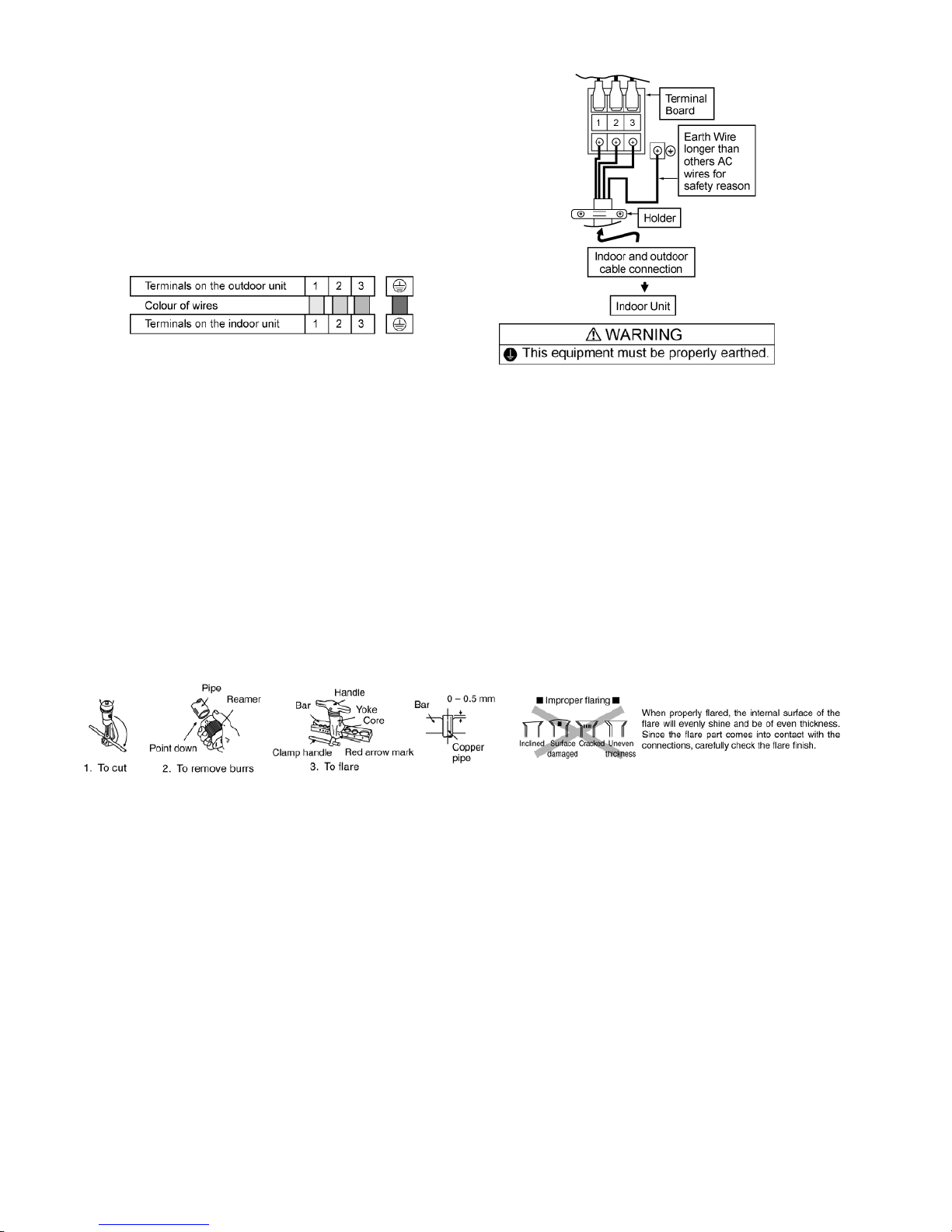
74
11.3.4 Connect the cable to the Outdoor Unit
6 Remove the control board cover from the unit
by loosening the screw.
7 Connection cable between indoor unit and
outdoor unit shall be approved
polychloroprene sheathed 4 × 1.5 mm
2
(1.0 ~
1.5HP) or 4 × 2.5 mm
2
(2.0 ~ 2.5HP) flexible
cord, type designation 60245 IEC 57 or
heavier cord. Do not use joint connection
cable. Replace the wire if the existing wire
(from concealed wiring, or otherwise) is too
short.
8 Secure the cable onto the control board with
the holder (clamper).
9 Attach the control board cover back to the
original position with screw.
10 For wire stripping and connection requirement,
refer to instruction g of indoor unit.
• Earth wire shall be Yellow/Green (Y/G) in colour
and longer than other AC wires for safety
reason.
11.3.5 Piping Insulation
3 Please carry out insulation at pipe connection portion as mentioned in Indoor/Outdoor Unit Installation
Diagram. Please wrap the insulated piping end to prevent water from going inside the piping.
4 If drain hose or connecting piping is in the room (where dew may form), please increase the insulation by
using POLY-E FOAM with thickness 6 mm or above.
11.3.5.1 Cutting and flaring the piping
4 Please cut using pipe cutter and then remove the burrs.
5 Remove the burrs by using reamer. If burrs is not removed, gas leakage may be caused. Turn the piping end
down to avoid the metal powder entering the pipe.
6 Please make flare after inserting the flare nut onto the copper pipes.
Page 75
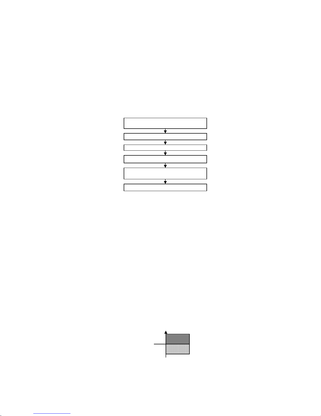
75
12. Operation Control
12.1 Basic Function
Inverter control, which equipped with a microcomputer in determining the most suitable operation mode as time
passes, automatically adjusts output power for maximum comfort always. In order to achieve the suitable operation
mode, the microcomputer maintains the set temperature by measuring the temperature of the environment and
performing temperature shifting. The compressor at outdoor unit is operating following the frequency instructed by
the microcomputer at indoor unit that judging the condition according to internal setting temperature and intake air
temperature.
12.1.1 Internal Setting Temperature
Once the operation starts, remote control setting temperature will be taken as base value for temperature shifting
processes. These shifting processes are depending on the air conditioner settings and the operation environment.
The final shifted value will be used as internal setting temperature and it is updated continuously whenever the
electrical power is supplied to the unit.
12.1.2 Cooling Operation
12.1.2.1 Thermostat control
• Compressor is OFF when intake Air Temperature - Internal Setting Temperature < -0.5°C.
• Compressor is ON after waiting for 3 minutes, if the Intake Temperature - Internal Setting Temperature >
Compressor OFF point.
12.1.3 Soft Dry Operation
12.1.3.1 Thermostat control
• Compressor is OFF when Intake Temperature - Internal Setting Temperature < -1.0°C.
• Compressor is ON after waiting for 3 minutes, if the Intake Air Temperature - Internal Setting Temperature >
Compressor OFF point.
12.1.3.2 Automatic Operation
• This mode can be set using remote control and the operation is decided by indoor intake air temperature.
• During operation mode judgment at the beginning of the Auto Mode operation, indoor fan motor (with speed of
Lo-) is running for 30 seconds to detect the indoor intake air temperature. Power indicator blinks during operation
mode judgment.
• The operation mode is decided based on below chart.
• After the operation mode is decided, the unit operation will follow the respective operation mode control.
Remote Control Setting Temperature
16°C ~ 30°C
Indoor Air Temperature Shifting
Outdoor Air Temperature Shifting
Powerful Mode Shifting
Setting Temperature Limit Checking
(Min: 16°C; Max: 33°C)
Internal Setting Temperature
Cooling
operation
Soft Dry
operation
Indoor intake
A
ir Tem
p
23°C
Page 76
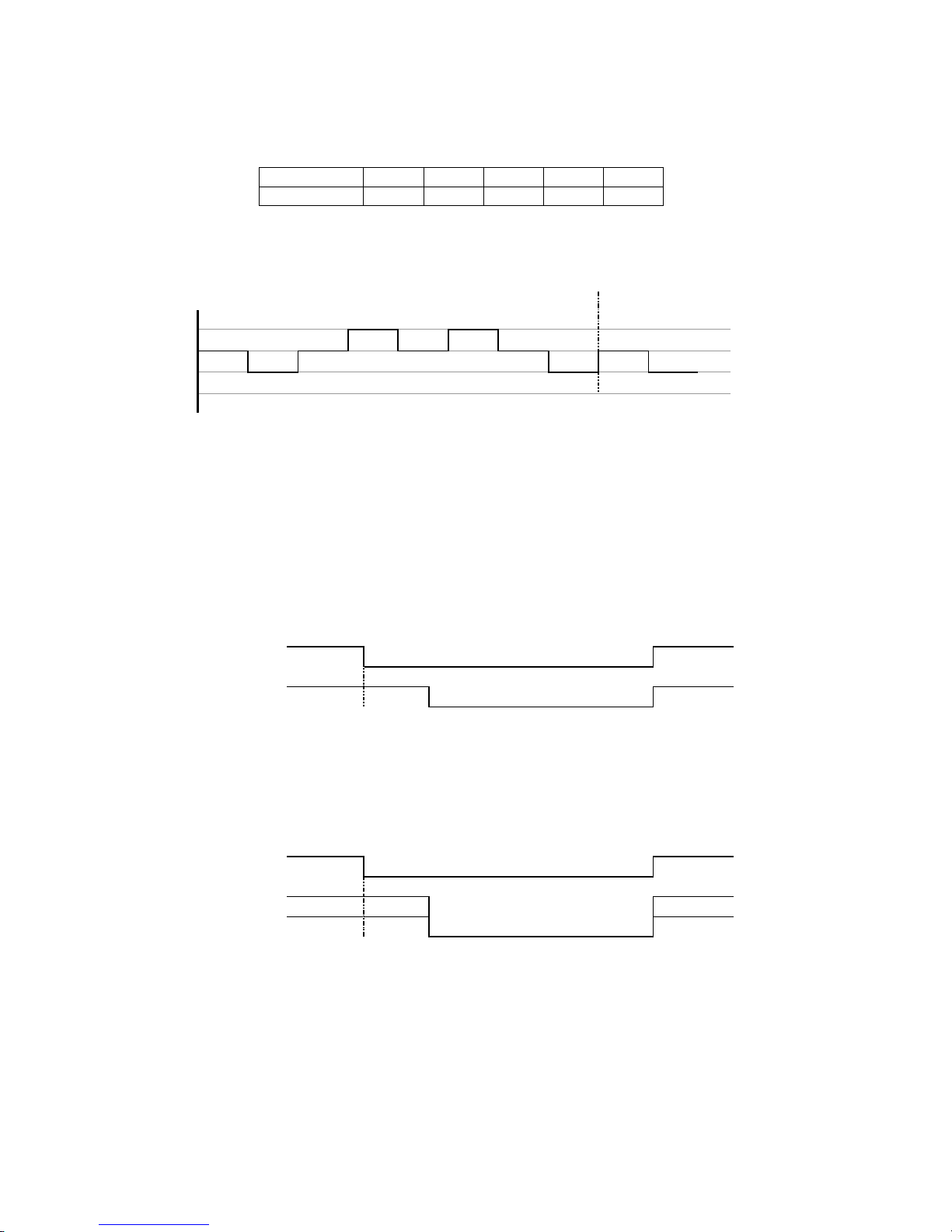
76
12.2 Indoor Fan Motor Operation
12.2.1 Basic Rotation Speed
• Manual Fan Speed
o Fan motor’s number of rotation is determined according to remote control setting.
Remote control ○ ○ ○ ○ ○
Tab Hi Me+ Me Me- Lo
• Auto Fan Speed
o According to room temperature and setting temperature, indoor fan speed is determined automatically.
o The indoor fan will operate according to pattern below.
Fan Speed a b c d e f g h a b
Higher
Medium
Lower
[1 pattern : 10s]
• Feedback control
o Immediately after the fan motor is started, feedback control is performed once every second.
o During fan motor on, if fan motor feedback ≥ 2550 rpm or <50 rpm continuously for 10 seconds, the fan
motor error counter increased; fan motor is then stopped and restarted. If the fan motor error counter
increased to 7, then H19 – fan motor error is detected. Operation stopped and could not be restarted.
12.3 Outdoor Fan Motor Operation (For S10/13/15/18PK)
Outdoor fan motor is operated with one fan speed only. Outdoor fan turns on when compressor starts to operate. But
outdoor fan will turns off 30 seconds after compressor stops to operate.
ON ON
Compressor OFF
ON Fan Speed ON
Outdoor Fan 30 sec OFF
12.4 Outdoor Fan Motor Operation (For S24PK)
There is 2 speeds for outdoor fan motor. Outdoor fan speed can be changed to Hi or SHi according to outdoor
temperature. By default, the outdoor fan speed is set to Hi. For Cooling or Soft Dry operation, when outdoor
temperature reaches 38°C the outdoor fan speed is set to SHi, when outdoor temperature reduced to 37°C the fan
speed will set to Hi again. Outdoor fan will turns off 30 seconds after compressor stops to operate.
ON ON
Compressor OFF
ON Fan Speed ON
Outdoor Fan 30 sec OFF
Page 77
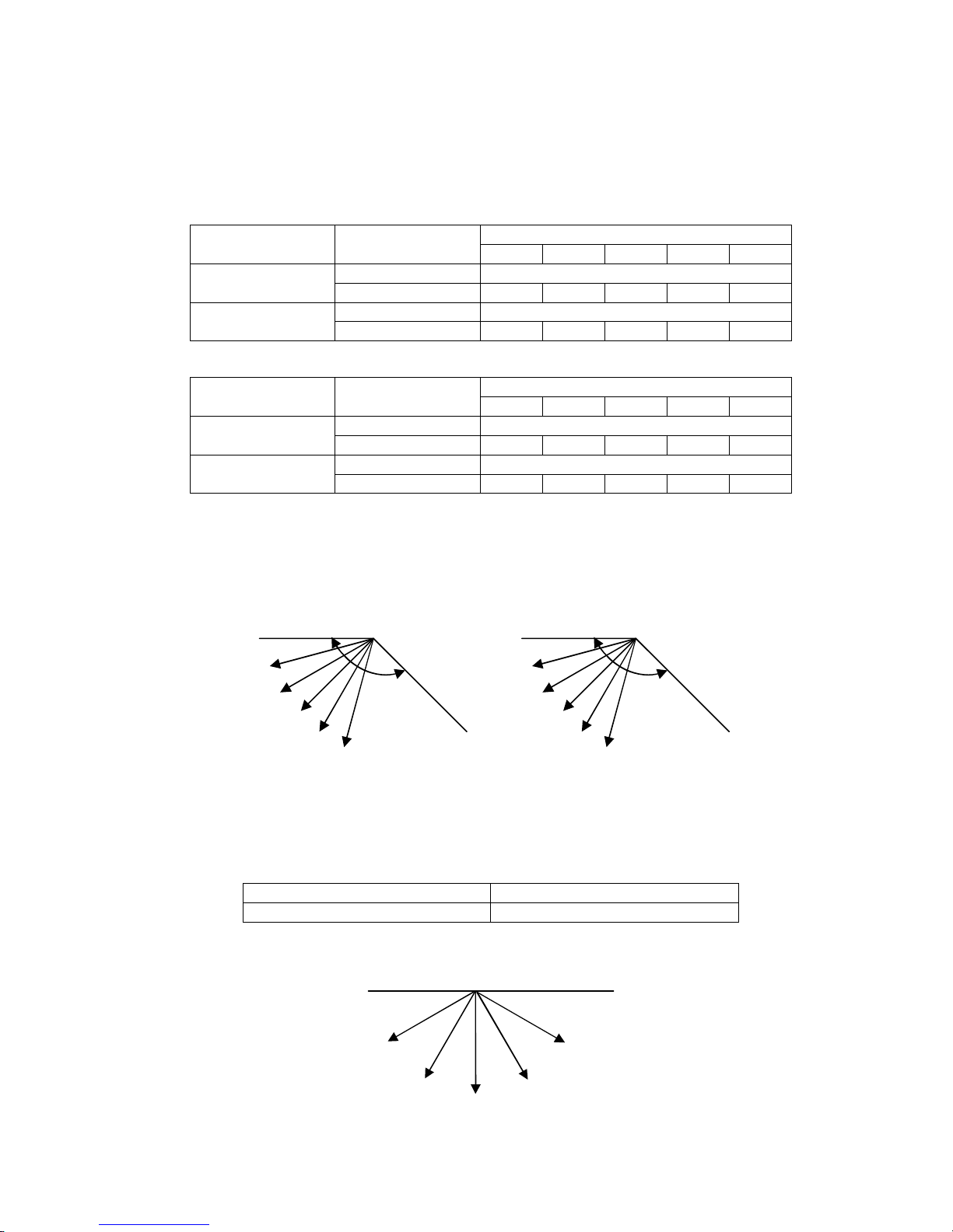
77
12.5 Airflow Direction
• There are two types of airflow, vertical airflow (directed by horizontal vane) and horizontal airflow (directed by
vertical vanes).
• Control of airflow direction can be automatic (angles of direction is determined by operation mode, heat
exchanger temperature and intake air temperature) and manual (angles of direction can be adjusted using
remote control).
12.5.1 Vertical Airflow
CS-S10, 13, 15PK
Vane Angle (°)
Operation Mode Airflow Direction
1 2 3 4 5
Auto 10 ~ 40
Cooling
Manual 10 17.5 25 32.5 40
Auto 10 ~ 40
Soft Dry
Manual 10 17.5 25 32.5 40
CS-S18, 24PK
Vane Angle (°)
Operation Mode Airflow Direction
1 2 3 4 5
Auto 5 ~ 35
Cooling
Manual 5 12.5 20 27.5 35
Auto 5 ~ 35
Soft Dry
Manual 5 12.5 20 27.5 35
• Automatic vertical airflow direction can be set using remote control; the vane swings up and down within the
angles as stated above. It does not swing during fan motor stop. When the air conditioner is stopped using
remote control, the vane will shift to close position.
• Manual vertical airflow direction can be set using remote control; the angles of the vane are as stated above and
the positions of the vane are as figure below. When the air conditioner is stopped using remote control, the vane
will shift to close position.
Side View
1
2
3
4
5
135°
Close position
CS-S10, 13, 15PK
Side View
1
2
3
4
5
140°
Close position
CS-S18, 24PK
12.5.2 Horizontal Airflow
• Automatic airflow direction can be set using remote control; the vane swings left and right within the angles as
stated below. It does not swing during fan motor stop.
Operation Mode Vane Angle (°)
Cooling and soft dry 60 ~120
• Manual vertical airflow direction can be set using remote control; the angles of the vane are as stated below and
the positions of the vane are as figure below:
1
2
34
5
Top View
Page 78
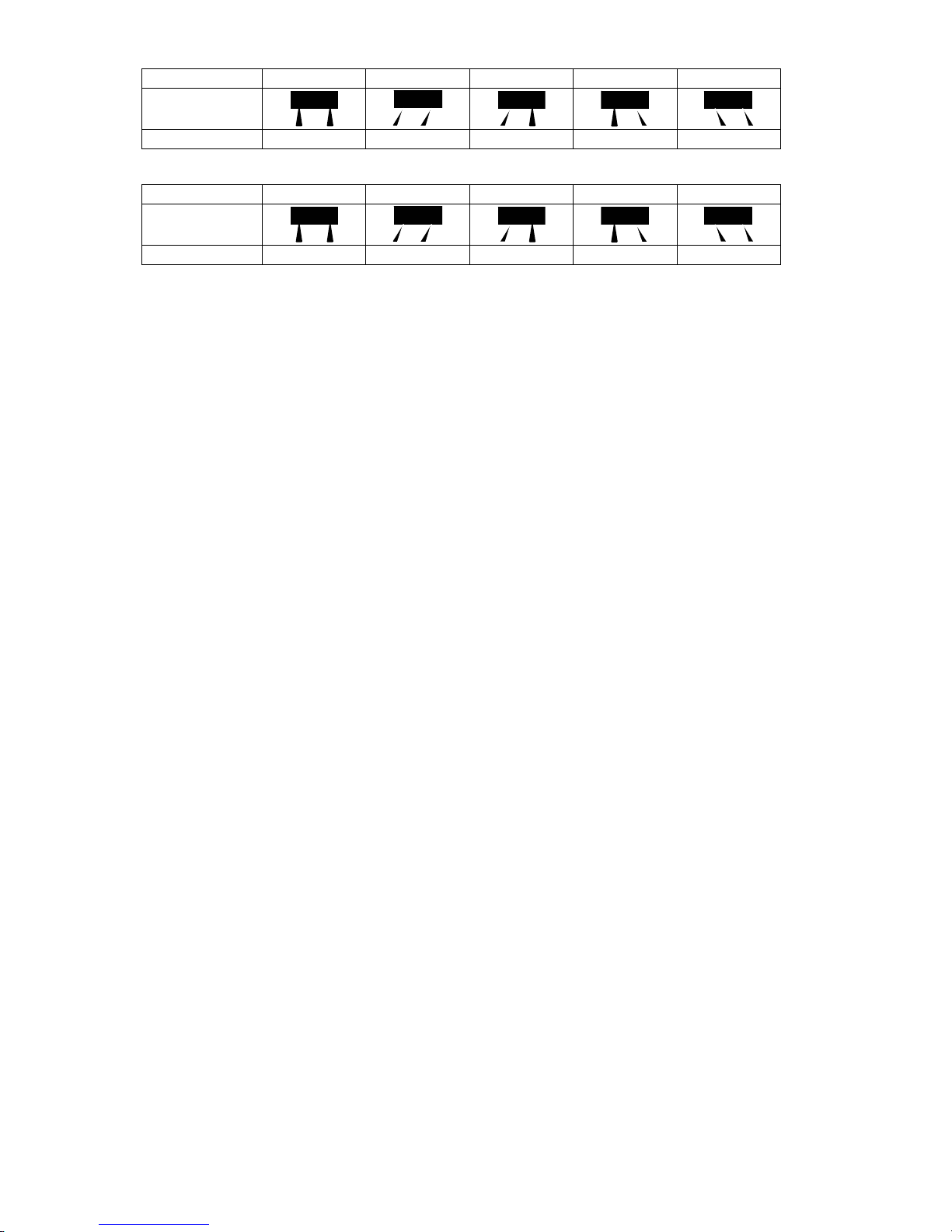
78
CS-S10, 13, 15PK
Pattern 1 2 3 4 5
Airflow Direction
Patterns at Remote
Control
Vane Angle (°) 90 65 77.5 102.5 115
CS-S18, 24PK
Pattern 1 2 3 4 5
Airflow Direction
Patterns at Remote
Control
Vane Angle (°) 90 70 80 100 110
12.6 Quiet Operation (Cooling Mode/Cooling Area of Dry Mode)
• Purpose
o To provide quiet cooling operation compare to normal operation.
• Control condition
o Quiet operation start condition
When Quiet button at remote control is pressed Quiet INDICATOR illuminates.
o Quiet operation stop condition
When one of the following conditions is satisfied, quiet operation stops:
• ECONAVI button is pressed.
• Powerful button is pressed.
• Mild Dry Cooling button is pressed.
• Stop by OFF/ON button.
• OFF Timer activates.
• Quiet button is pressed again.
When quiet operation is stopped, operation is shifted to normal operation with previous setting.
When fan speed is changed, quiet operation is shifted to quiet operation of the new fan speed.
When operation mode is changed, quiet operation is shifted to quiet operation of the new mode.
During quiet operation, if ON timer activates, quiet operation maintains.
After off, when on back, quiet operation is not memorized.
• Control content
o Fan speed is changed from normal setting to quiet setting of respective fan speed. This is to reduce sound of
Hi, Me, Lo for 3dB (more than 3dB for some models).
o Fan speed for quiet operation is -1 step from setting fan speed.
12.7 Powerful Mode Operation
• When the powerful mode is selected, the internal setting temperature will shift lower up to 2°C (for Cooling/Soft
Dry) than remote control setting temperature for 240 minutes and the fan speed will increase to achieve the
setting temperature quickly.
• Powerful operation stops condition
o When one of the following condition is satisfied, powerful operation stops:
ECONAVI button is pressed.
Quiet button is pressed.
Mild Dry Cooling button is pressed.
Stop by OFF/ON button.
OFF Timer activates.
Powerful button is pressed again.
Powerful operation continue for 240 minutes.
Page 79
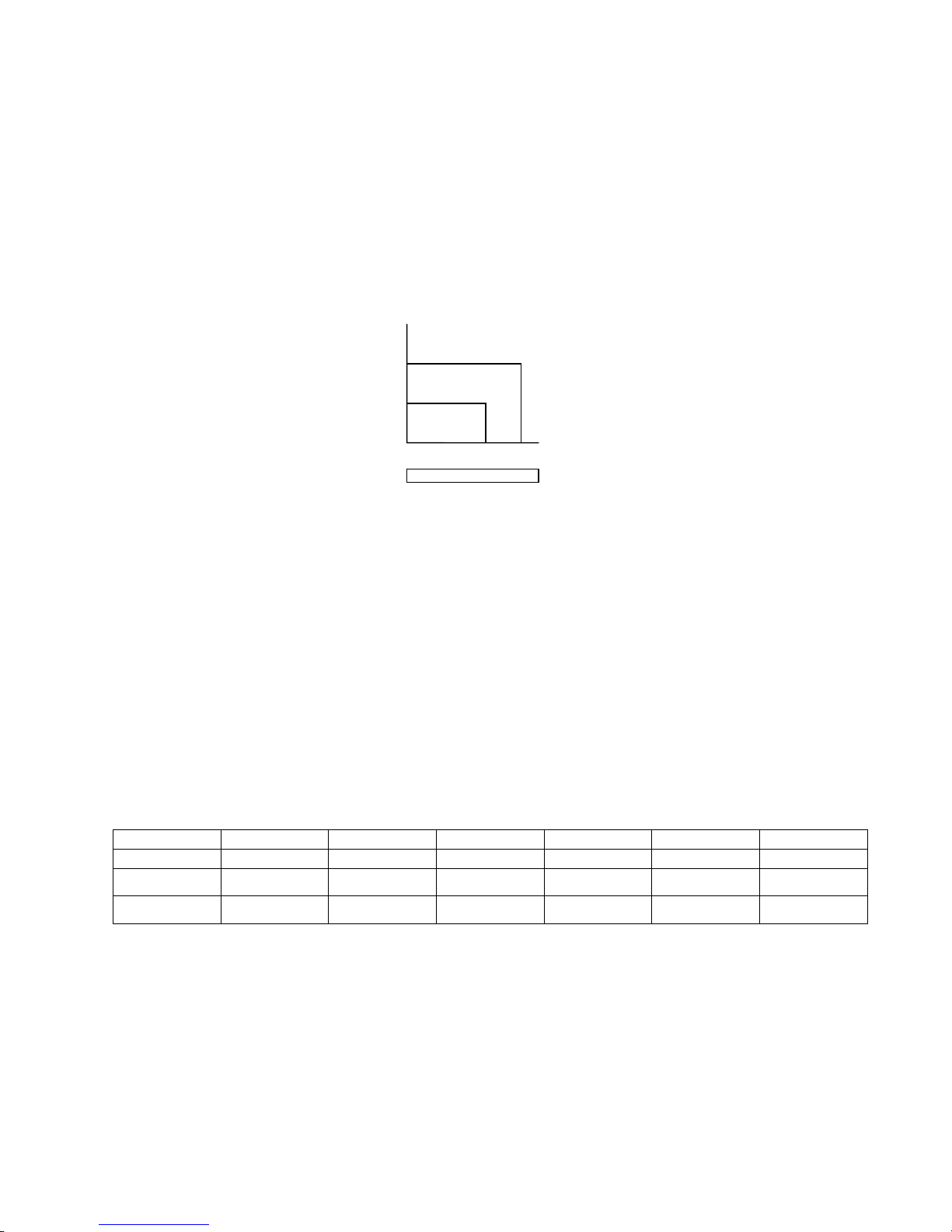
79
12.8 Timer Control
• There are 2 sets of ON and OFF timer is available to turn the unit ON or OFF at different preset time.
• If more than one timer had been set, the upcoming timer will be display and will activated in sequence.
12.8.1 ON Timer Control
ON Timer 1 and ON Timer 2 can be set using remote control, where the unit with timer set will start operation earlier
than the setting time. This is to provide a comfortable environment when reaching the set ON time.
60 minutes before the set ON time, indoor (at fan speed of Lo-) and outdoor fan motor start operation for 30 seconds
to determine the indoor intake air temperature and outdoor air temperature in order to judge the operation starting
time.
From the above judgment, the decided operation will start operation earlier than the set time as shown below.
12.8.2 OFF Timer Control
OFF Timer 1 and OFF Timer 2 can be set using remote control, where the unit with timer set will stop at set OFF time.
Notes:
1 By pressing ON/OFF operation button, the ON Timer or OFF Timer setting will not be cancelled.
2 To cancel the previous timer setting, press CANCEL button.
3 To activate the previous timer setting, press SET button.
4 If main power supply is switched off, the Timer setting will be cancelled.
12.9 Random Auto Restart Control
• When the power supply is cut off during the operation of air conditioner, the compressor will re-operate within
three to four minutes. There are 10 patterns to be selected randomly after power supply resumes.
• This control is not applicable during OFF/ON Timer setting.
• This control can be omitted by open the circuit of JP1 at indoor unit printed circuit board.
12.10 Indication Panel
LED POWER TIMER AUTO COMFORT NANOE-G QUIET POWERFUL
Color Green Orange Green Blue Orange Orange
Light ON Operation ON Timer Setting ON
Auto Comfort
Mode ON
Nanoe-G
Mode ON
Quiet Mode ON Powerful Mode ON
Light OFF Operation OFF Timer Setting OFF
Auto Comfort
Mode OFF
Nanoe-G
Mode OFF
Quiet Mode OFF Powerful Mode OFF
Note:
• If POWER LED blinks, the possible operation of the unit is operation mode judgment, or ON timer sampling.
• If TIMER LED blinks, there is an abnormal operation occurs.
15 min
10 min
5 min
Indoor intake air
tem
p
erature (°C
)
30
25
30 35
Outdoor air
tem
p
erature (°C
)
Cooling / Soft Dr
y
Page 80

80
12.11 nanoe-G Operation
• This operation provides clean air by producing great amount of negative ions and distribute through the
discharge airflow to capture or deactivate molds, bacteria or viruses.
• nanoe-G operation start condition
o During unit running at any operation mode, if nanoe-G operation is activated, combination operation
(operation mode + nanoe-G operation) starts.
o During unit is OFF, if nanoe-G operation is activated, nanoe-G individual operation starts.
• nanoe-G operation stop condition
o When OFF/ON button is pressed to stop the operation.
o When nanoe-G button is pressed.
o When OFF Timer activates.
• nanoe-G operation pause condition
o When indoor fan stop (during deice, odor cut control, thermostat off, etc.). nanoe-G operation resume after
indoor fan restarts.
o When indoor intake temperature ≥ 40°C. nanoe-G operation resume after indoor intake temperature ≤ 40°C
continuously for 30 minutes.
• Indoor fan control
o During any operation mode combines with nanoe-G operation, fan speed follows respective operation mode.
However, nanoe-G system enabled when fan speed ≥ 500rpm to ensure proper negative ion distribution,
nanoe-G system disabled when fan speed < 500 rpm.
o During nanoe-G individual operation, only Auto Fan Speed and no Powerful operation is allowed. Even if Fan
Speed button is pressed, no signal is sent to the unit and no change on remote control display. Auto Fan
Speed for nanoe-G operation changes from SHi to Hi after 4 hours of operation.
• Airflow direction control
o During any operation mode combines with nanoe-G operation, airflow direction follows respective operation
mode.
o During nanoe-G individual operation, only Auto Air Swing is allowed. Even if Air Swing button is pressed, no
signal is sent to the unit and no change on remote control display.
• Timer control
o When ON Timer activates when unit stops, previous operation resumes and restored last saved nanoe-G
operation status.
o When ON Timer activates during any operation, no change on current operation.
o When OFF Timer activates during any operation, all operation stops and the latest nanoe-G operation status
is saved.
• Indicator
o When nanoe-G starts, nanoe-G indicator ON.
• Remote control receiving sound
o Normal operation Î nanoe-G operation : Beep
o Nanoe-G operation Î Normal operation : Beep
o Stop Î nanoe-G individual operation : Beep
o Nanoe-G individual operation Î Stop : Long Beep
• Powe
r failure
o During nanoe-G individual operation, if power failure occurs, after power resumes, nanoe-G individual
operation resumes immediately.
o During combination operation, if power failure occurs, after power resumes, combination operation resume
immediately.
Page 81
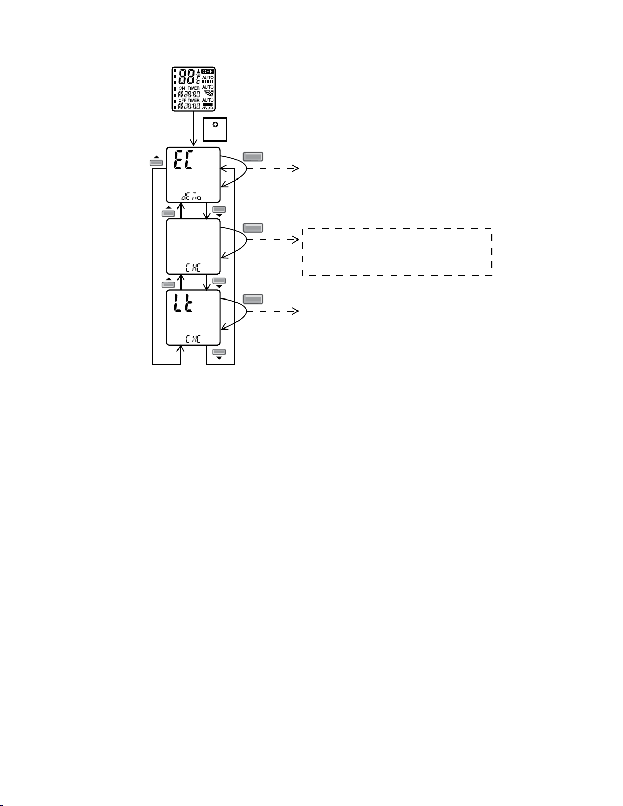
81
• nanoe-G check mode
o To enable nanoe-G check mode, during nanoe-G operation ON:
SET
SET
Transmit ECO demo code
and after 2 seconds return to normal
mode.
Press continously for 15s
SET
Transmit check code
and after 2 seconds return to normal
mode.
SET
Transmit sunlight sensor check code
and after 2 seconds return to normal
mode.
Remote control normal mode
o If there is abnormal discharge, nanoe-G indicator blinks immediately.
• Error detection control
When nanoe-G indicator blinks, it indicates error listed below:
o Nanoe-G connector at main PCB open
Judgment method
• During nanoe-G operation, nanoe-G connector at main PCB is opened.
Troubleshooting method
• Connect the connector or stop operation to cancel the blinking.
• Switch off the power supply and unplug before cleaning.
• Clean the dirty nanoe-G generator with cotton bud.
o Abnormal discharge error
Judgment method
• During nanoe-G operation, the nanoe-G system has abnormal discharge due to short-circuit caused
by water or dust adhesion and so forth, with Lo-feedback voltage (at microcontroller).
• When abnormal discharge occurred, every 30 minutes the unit supplies power to the nanoe-G
system.
• When abnormal discharge occurs for 48 times continuously, nanoe-G indicator blinks.
Troubleshooting method
• Press nanoe-G button or OFF/ON button to stop the operation and check the nanoe-G connector at
PCB.
• After that, press nanoe-G button again to confirm the nanoe-G indicator do not blinks.
• The 24 timer counter will be clear after 10 minutes of normal operation or when operation stops.
Error reset method
• Press “OFF/ON” button to OFF the operation.
• Press AUTO OFF/ON button at indoor unit to OFF the operation.
• OFF Timer activates.
• Power supply reset.
Page 82

82
o nanoe-G breakdown error
Judgment method
• Hi-feedback voltage (at microcontroller) supplied to the nanoe-G system when nanoe-G operation is
OFF; nanoe-G breakdown error show immediately.
• It is due to indoor PCB or nanoe-G high voltage power supply damage.
• Operations except nanoe-G continue. Both Timer indicator and nanoe-G indicator blink.
Troubleshooting method
• Press nanoe-G button or OFF/ON button to stop the operation.
• Change nanoe-G high voltage power supply or main PCB.
• When Lo-feedback voltage supplied to nanoe-G system during nanoe-G operation ON, nanoe-G
indicator and Timer indicator stop blinking.
12.12 In-filter Deactivation Operation
• This operation helps to deactivate virus and bacteria on filter after the unit turned off using nanoe-G generator.
• In-filter deactivation start condition
o nanoe-G is ON before the unit is turned off either by OFF/ON button or OFF Timer.
o Elapsed time from previous in-filter deactivation operation is more than 24hrs.
o Unit operation time before unit is turned off is more than 2 hours or accumulated unit operation time achieves
4hrs if unit operation time less than 2hours.
• In-filter deactivation stop condition
o The unit is turned on.
o nanoe-G generator operation time during in-filter deactivation operation has achieved 120 minutes.
o The unit received disable signal from remote control.
o Nanoe-G abnormality occurs.
• Control contents:
o When the unit operate in Cool or Dry mode before turned off.
1. The unit will operate fan operation, fan motor will operate at 500rpm for 30 minutes then stop.
2. During fan operation, horizontal vane will fixed at 115° for 30 minutes then close.
3. After 30 minutes the unit will continue with common control.
o Common control.
- nanoe-G generator will operate for 120 minutes.
• Timer control
o When ON Timer activates during in filter deactivation operation, in-filter deactivation operation stops.
o When OFF Timer activates during in filter deactivation operation, in-filter operation will continue.
• Indicator
o nanoe-G indicator ON.
o Power indicator OFF.
• Enable or disable selection
o Press NANOE-G button continuously for 5 seconds to disable or enable in-filter deactivation operation.
• Remote control receiving sound
o Enable in-filter deactivation operation : Beep
o Disable in-filter deactivation operation : Long beep
• Power failure
o During in-filter operation, if power failure occurs, after power resumes in-filter deactivation operation will not
resume.
Page 83
83
12.13 Mild Dry Cooling Operation
• This operation helps to prevent decreases in room humidity while maintaining the setting temperature.
• During unit running at Cooling operation mode, if “Mild Dry Cooling” button is pressed, Mild Dry Cooling operation
starts and Mild Dry Cooling indicators turns ON at remote control display.
• Mild dry cooling operation is unavailable when the unit is operating Auto mode, Soft Dry mode, Patrol individual
operation or e-ion individual operation.
• Mild dry cooling operation is cancelled when the unit turned OFF, pressed again Mild Dry Cooling button or when
the operation mode changed from Cooling to other mode.
• ECONAVI, Powerful, Quiet and Mild Dry Cooling mode cannot function at the same time, the unit will follows the
operation according to the last signal received.
• During this operation, the compressor frequency changes according to operating condition to prevent room
humidity decreases and when AUTO AIR SWING is set, the vertical airflow direction fixed at lower limit position.
12.14 AUTO COMFORT and ECONAVI Operation
• Area of human availability, activity level and absent is judged based on pulses by using 2 infrared sensors. The
internal setting temperature shift, fan speed and horizontal airflow direction are adjusted in order to provide
comfort environment while maintain the energy saving level.
• AUTO COMFORT start condition:
When AUTO COMFORT button is pressed.
• AUTO COMFORT stop conditions:
When AUTO COMFORT button is pressed again.
When unit is OFF by OFF/ON button.
When unit is OFF when OFF TIMER activates.
When unit is OFF by AUTO OFF/ON button at indoor unit.
When POWERFUL, QUIET or MILD DRY operation activates.
When ◄► button is pressed.
• ECONAVI start condition:
When ECONAVI button is pressed.
• ECONAVI stop conditions:
When ECONAVI button is pressed again.
When unit is OFF by OFF/ON button.
When unit is OFF when OFF TIMER activates.
When unit is OFF by AUTO OFF/ON button at indoor unit.
When POWERFUL, QUIET or MILD DRY operation activates.
When ◄► button is pressed.
• AUTO COMFORT / ECONAVI initialization
Initialize indication Human Activity Indicator
1 0 – 2 seconds □ □ □
2 2 – 3 seconds ■ ■ ■
I ■ □ ■
II ■ ■ □
III ■ □ ■
IV □ ■ ■
3 3 – 70 seconds
Repeat Step I to IV
* □ Indicator ON, ■ Indicator OFF
Page 84
84
12.14.1 Human Activity Sensor
• Area of human availability, activity level and absent is judged based on pulses by using 2 infrared sensors. The
internal setting temperature shift, fan speed and horizontal airflow direction are adjusted in order to provide
comfort environment while maintain the energy saving level.
• AUTO COMFORT / ECONAVI initialization
Initialize indication Human Activity Indicator
1 0 – 2 seconds □ □ □
2 2 – 3 seconds ■ ■ ■
I ■ □ ■
II ■ ■ □
III ■ □ ■
IV □ ■ ■
3 3 – 70 seconds
Repeat Step I to IV
* □ Indicator ON, ■ Indicator OFF
• Human activity judgment is as following
Signal Detection
Information Log
Area of Living Classification Judgment
HumanPositionAnalysis
Target Area & Position Judgment
Human Activity Level Judgment
Setting Position Judgment
Page 85
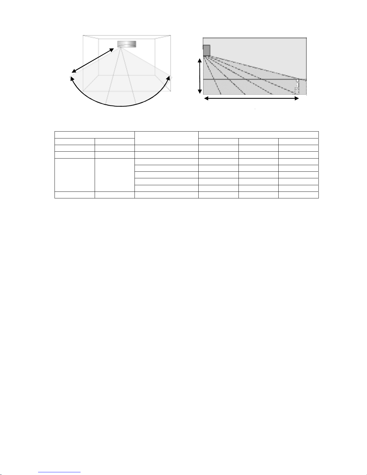
85
12.14.1.1 Signal Detection
7m
120º
A
B
C
2m
7m
• Human Activity sensor will turns on according to infrared sensors signal detection.
Signal detection Human Activity Indicator
Sensor 1 Sensor 2
Possible detected human
position area
Left Center Right
1 0 C ■ ■ □
0 1 A □ ■ ■
B ■ □ ■
A & C ■ □ ■
B & C ■ □ ■
A & C ■ □ ■
1 1
A, B & C ■ □ ■
0 0 - ■ ■ ■
* □ Indicator ON, ■ Indicator OFF
• However, once the Human Activity Indicator is ON, it will maintain ON status for 5 seconds. If there is no signal
detection from either infrared sensor, the final display condition will be kept until absence status.
12.14.1.2 Information Log
• The signal from Infrared sensors will be log to human activity database for further analysis.
12.14.1.3 Area of Living Classification Judgment
• The system is able to judge area of living according to human activity database, classified as following:
Living Area – In front of television, dining table, etc.
Walkway – Human detection is relatively less.
Non-Living Area – near windows, wall, etc.
12.14.1.4 Human Position Analysis
• According to Area of Living, frequency of activity and indoor unit intake temperature, the system will analyze the
human position away from the indoor unit.
12.14.1.5 Target Area and Position Judgment
• The system will judge the indoor unit installation position according to human activity Non-Living Area:
Non-Living Area at Position A – Indoor unit installed at left side of the room.
Non-Living Area at Position C – Indoor unit installed at right side of the room.
Other than above – Indoor unit installed at center of the room.
• Every 4 hours, the Target Area and Position Judgment will restart.
12.14.1.6 Human Activity Level Judgment
• Human Activity Level is judged based on the frequency of pulses detected by the infrared sensors within a
timeframe. The activity level will be categorized into High, Normal, Low level.
• When a pulse is detected within this timeframe, the status of human presence is judged.
• When there is no signal detection continues for 20 minutes or more, the status of human absence is judged.
Page 86
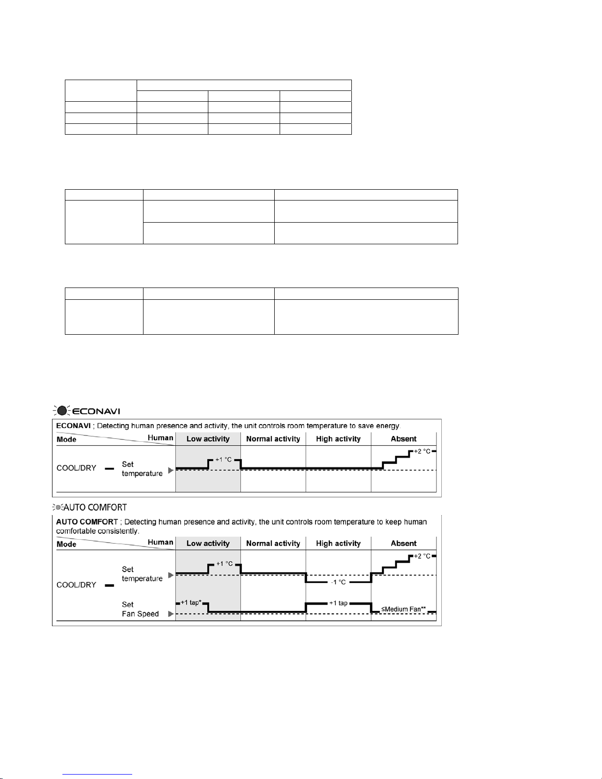
86
12.14.1.7 Setting Position Judgment
• According to installation position when there is only one activity area detected, the horizontal airflow direction
louver position is fixed according to chart below:
Horizontal airflow direction louver position
Target area
Left installation Center installation Right installation
A 3 2 2
B 1 1 1
C 5 5 4
• Louver position refer to horizontal airflow direction control.
• When 2 activity areas have been detected, according to Human Activity Level, the timing of horizontal airflow
direction louver steps at the targeted activity areas is judged.
Operation Mode Activity level difference Louver stop time
Higher Activity level ≈ 60 seconds
1 level
Lower Activity level ≈ 30 seconds
Higher Activity level ≈ 60 seconds
Cooling
2 levels
Lower Activity level ≈ 8 seconds
• When 3 activity areas have been detected, according to Human Activity Level the timing of horizontal airflow
louver steps at the targeted activity areas is judged.
Operation Mode Activity level Louver stop time
Hi ≈ 45 seconds
Me ≈ 30 seconds
Cooling
Lo ≈ 20 seconds
• When 3 activity areas have same activity level, the horizontal airflow direction louver will swing left and right.
12.14.1.8 Setting Temperature and Fan Speed Shift
• Cooling Dual Sensor
* During low activity, fan speed 1 tap up for first 15 minutes or until set temperature is reached.
** During human absence, maximum fan speed for COOL/DRY mode is medium fan.
Page 87
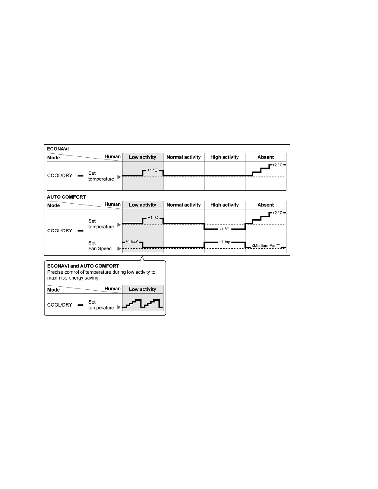
87
12.14.1.9 Rhythmic Temperature Wave Operation
• To further maximize the energy saving during ECONAVI or AUTO COMFORT operates at low activity level.
• Start condition
o The unit is operates in Cool or Dry mode under ECONAVI or AUTO COMFORT operation, and
o Human activity sensor detects low activity level continuously for 60 minutes, and
o ON Timer is not activated.
• Stop condition
o Unit is off, or
o ECONAVI or AUTO COMFORT is off, or
o Human activity sensor detects high activity level or absent, or
o ON Timer is activated.
• Control contents
o When all start conditions complied, set temperature will shift accordingly as following:
Page 88
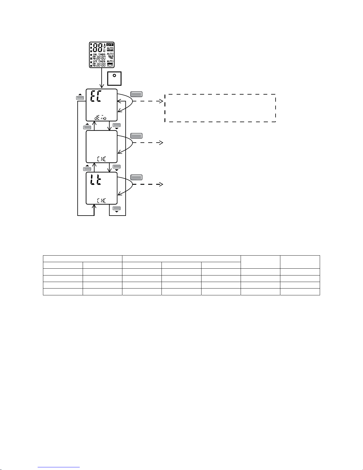
88
12.14.1.10 ECONAVI and AUTO COMFORT Demo Mode
• To enable ECO DEMO mode:
SET
SET
Transmit ECO demo code
and after 2 seconds return to normal
mode.
Press continously for 15s
SET
Transmit check code
and after 2 seconds return to normal
mode.
SET
Transmit sunlight sensor check code
and after 2 seconds return to normal
mode.
Remote control normal mode
• To disable ECO Demo MODE:
Transmit ECO Demo signal again.
• Operation details
Infrared Sensor Human Activity Indicator
Sensor 1 Sensor 2 Left Center Right
Vane Position Fan Speed
1 0 ■ ■ □ 5 HI
1 1 ■ □ ■ Auto Swing HI
0 1 □ ■ ■ 1 HI
0 0 ■ ■ ■ Auto Swing LO
• The target area will maintain for 5 seconds before changeover to next detection.
• If no activity detection, the last action will maintain for 30 seconds before changeover to human absence status.
Page 89
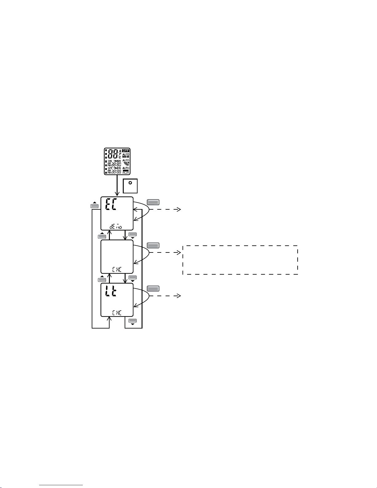
89
12.14.1.11 Human Activity Sensor Abnormality
• Abnormality detection:
Connector disconnection / Wire cut abnormality
o Sensor judge Hi level continuously for 25 seconds
Circuit abnormality
o 70 seconds after power ON, if human activity sensor judge Lo level continuously for 25 seconds
• Error Code judgment
When abnormality happened, internal counter increase by 1 time.
Human activity sensor power OFF, retry after 5 seconds.
When the human activity sensor maintains normal condition for 120 seconds, the counter reset or AC reset.
When abnormality counter reached 4 times, H59 occurred – No TIMER indicator blinking.
• When error code happened, the unit is able to operate without AUTO COMFORT / ECONAVI.
12.14.1.12 Human Activity Sensor Check Mode
• To enable human activity sensor abnormality check mode:
SET
SET
Transmit ECO demo code
and after 2 seconds return to normal
mode.
Press continously for 15s
SET
Transmit check code
and after 2 seconds return to normal
mode.
SET
Transmit sunlight sensor check code
and after 2 seconds return to normal
mode.
Remote control normal mode
• During ECONAVI is ON, when CHECK signal received, if either sensors has abnormality, the 4 times abnormality
counter is ignored, ECONAVI Indicator will blink immediately and error code is memorized.
• The unit could operate without ECONAVI or AUTO COMFORT.
• The ECONAVI indicator blinking could be cancelled by pressing ECONAVI button again.
• If the human activity sensor has no abnormality, the CHECK process will end and continue with normal operation.
Page 90
90
12.14.2 Sunlight Sensor
• During ECONAVI operation, the sunlight sensor detects sunlight intensity coming through windows and
differentiates between sunny and cloudy or night to further optimize energy saving by adjusting the temperature.
• Sunlight judgment is as following
Sunlight intensity reset
Judge sunlight intensity
Judge ambient condition
Temperature shift
12.14.2.1 Sunlight Intensity Reset
• The sunlight intensity will to reset to zero (no sunlight condition) when
o Each time ECONAVI is activated.
o Setting temperature is changed.
o Operation mode is changed.
Page 91
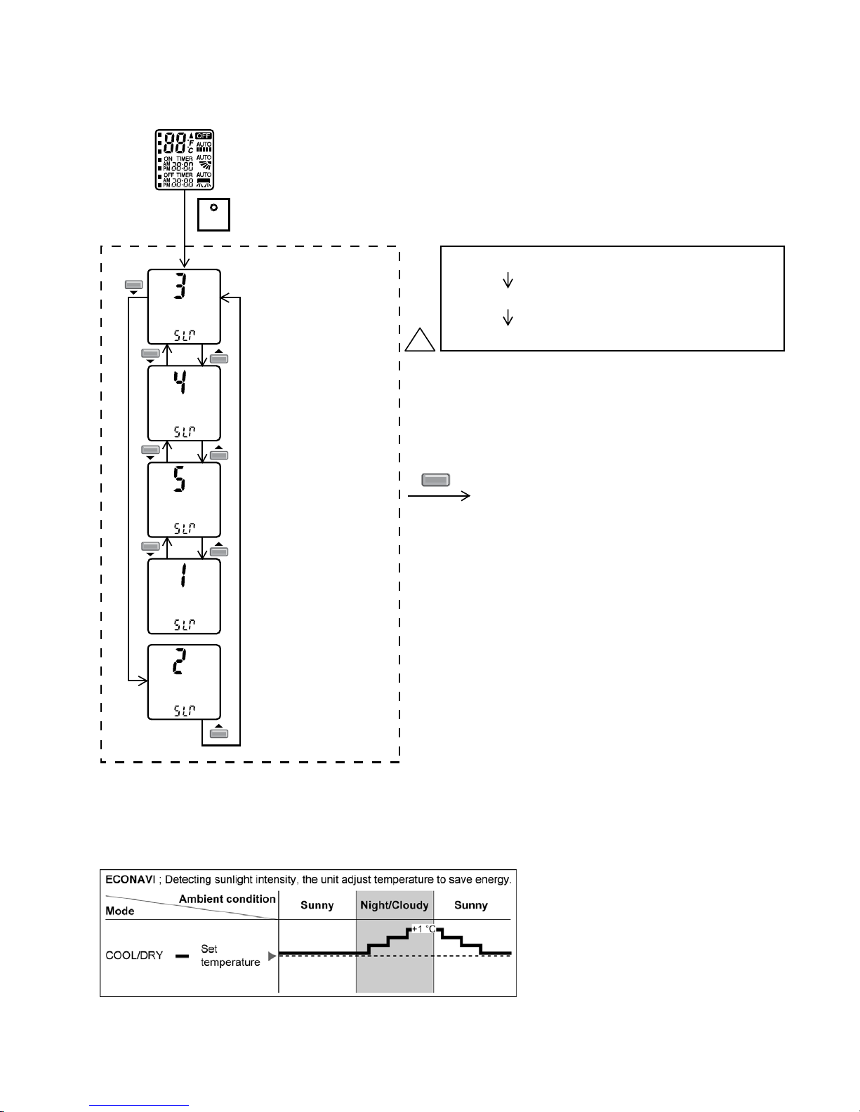
91
12.14.2.2 Judge Sunlight Intensity
• Based on sunlight sensor output voltage, the sunlight intensity value will be computed and logged to sunlight
intensity database.
• The sunlight sensor sensitivity could be adjusted:
SET
Press & release within 10s
Sensitivity Level 1: Less sensitive to sunlight intensity
Sensitivity Level 3: Default sensitive level
Sensitivity Level 5: More sensitive to sunlight intensity
Default: (Battery insert)
Set to Level. 3
Other than default
Display last set data
Transmit
solar radiation
level
&
after *2 secs
go back to
normal mode
Set to Level. 4
Press
Timer
1
Set to Level. 5
Set to Level. 1
Set to Level. 2
Remote control normal mode
SET
12.14.2.3 Judge Ambient Condition
• According to sunlight intensity over a period of time, the system will analyze the ambient condition is sunny,
cloudy or night.
12.14.2.4 Temperature Shift
• In a room without window or with thick curtain, the sunlight sensor will judge as cloudy/night.
Page 92
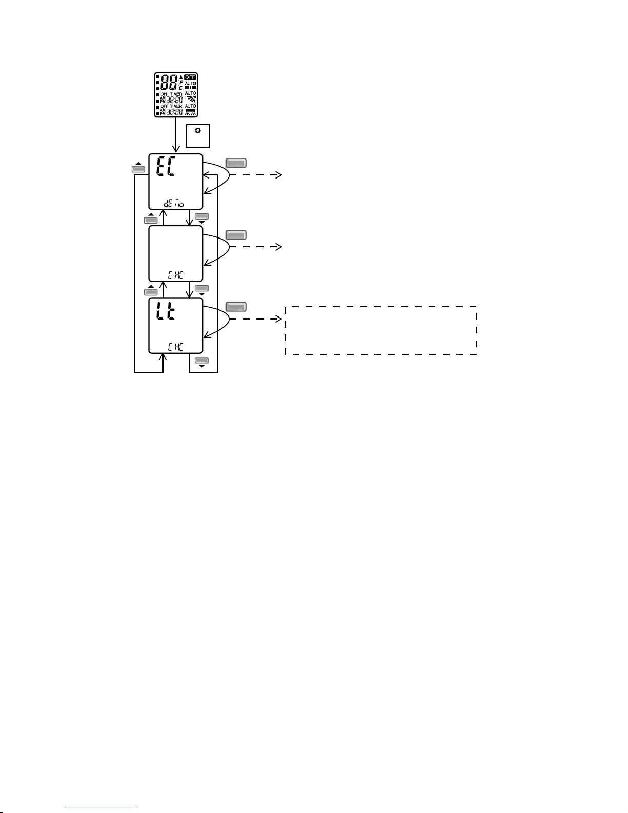
92
12.14.2.5 Sunlight Sensor Check Mode
• To enable sunlight sensor check mode, during unit is OFF (power standby):
SET
SET
Transmit ECO demo code
and after 2 seconds return to normal
mode.
Press continously for 15s
SET
Transmit check code
and after 2 seconds return to normal
mode.
SET
Transmit sunlight sensor check code
and after 2 seconds return to normal
mode.
Remote control normal mode
• Operation details
o The sunlight sensor check mode will be operated for 5 minutes.
o During check mode, the ON and OFF timer will be memorized but it operation be ignored.
o During check mode, if the sunlight sensor check code is retransmitted, the 5 minutes counter will be reset.
o During check mode, if sunlight sensor detected the sunlight intensity value above minimum level, the
ECONAVI indicator turns ON. Else if sunlight sensor detected sunlight intensity value below minimum level,
the ECONAVI indicator is OFF.
• To disable sunlight sensor check mode
o After check mode is ended (5 minutes counter elapsed), press AUTO OFF/ON button at indoor unit.
o If the sunlight sensor detected sunlight intensity is at abnormal range, the check mode will be ended.
Please check for error code.
12.14.2.6 Sunlight Sensor Abnormality
• Abnormality detection:
o When ECONAVI is ON, if the sunlight intensity value below minimum level continuously for 24 hours, the
sunlight sensor disconnection error counter will increase by 1 time. If the ECONAVI is OFF, the 24 hours
timer will be reset, but the sunlight sensor disconnection error counter will not be reset.
• Error Code judgment
o When sunlight sensor disconnection error counter reached 15 times. H70 occurred.
o No TIMER indicator or ECONAVI indicator blink.
• When error code happened, the unit is able to operate without sunlight sensor.
Page 93
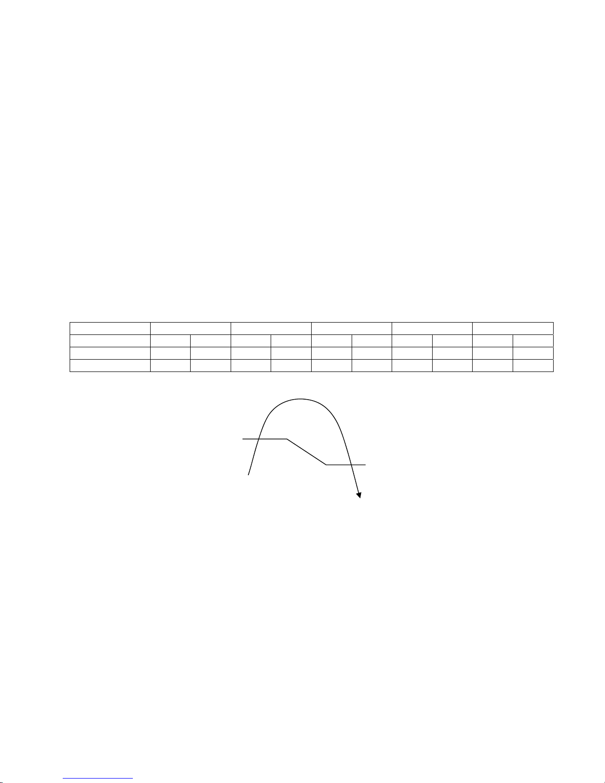
93
13. Protection Control
13.1 Restart Control (Time Delay Safety Control)
• The compressor will not turn on within 3 minutes from the moment operation stops, although the unit is turned on
again by pressing OFF/ON button at remote control within this period.
• This control is not applicable if the power supply is cut off and on again.
• This phenomenon is to balance the pressure inside the refrigerant cycle.
13.2 30 Seconds Forced Operation
• Once the air conditioner is turned on, the compressor will not stop within 30 seconds in a normal operation
although the intake air temperature has reached the thermo-off temperature. However, force stop by pressing the
OFF/ON button at the remote control is permitted or the Auto OFF/ON button at indoor unit.
• The reason for the compressor to force operation for minimum 30 seconds is to allow the refrigerant oil run in a
full cycle and return back to the outdoor unit.
13.3 Total Running Current Control
• When the outdoor unit total running current (AC) exceeds X value, the frequency instructed for compressor
operation will be decreased.
• If the running current does not exceed X value for 5 seconds, the frequency instructed will be increased.
• However, if total outdoor unit running current exceeds Y value, compressor will be stopped immediately for 3
minutes.
Model S10*** S13*** S15*** S18*** S24***
Operation Mode X (A) Y (A) X (A) Y (A) X (A) Y (A) X (A) Y (A) X (A) Y (A)
Cooling / Soft Dry (A) 5.6 15.0 7.1 15.0 8.3 15.0 10.8 15.0 11.8 19.0
Cooling / Soft Dry (B) 5.2 15.0 6.6 15.0 7.7 15.0 10.3 15.0 11.3 19.0
• The first 30 minutes of cooling operation, (A) will be applied.
13.4 IPM (Power Transistor) Prevention Control
• DC Peak Current Control
o When electric current to IPM exceeds set value of 13.2A (S10PK), 13.1A (S13PK), 17.1A (S15, 18PK),
27.7A (S24PK) within 30 seconds, the compressor will stop operation. Then, operation will restart after 1
minute.
o For second occurrence onwards, if the set value exceeds again within 30 seconds, the compressor will stop
operation. Then, operation will restart after 2 minutes.
o If this condition repeats continuously for 7 times, all indoor and outdoor relays will be cut off, timer LED will
be blinking “(“F99” is indicated).
• Overheating prevention
o When the IPM temperature raises to 120°C the compressor will stop immediately.
o Compressor operation restarts after 3 minutes the temperature decreases to 115°C.
o If this condition repeats continuously 4 times within 20 minutes, timer LED will be blinking (“F96” is indicated).
(B)
(A)
Outdoor air temperature
38.5°C
37.5°C
Page 94
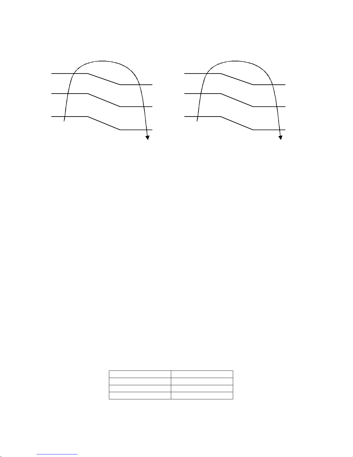
94
13.5 Compressor Overheating Prevention Control (For S18, S24PK only)
• Instructed frequency for compressor operation will be regulated by compressor discharge temperature. The
changes of frequency are as below.
• If compressor discharge temperature exceeds 112°C, compressor will be stopped, occurs 4 times per 20 minutes,
timer LED will be blinking. “F97” is indicated.
Compressor=OFF
Compressor Frequency
Reduced
Compressor Frequency
Maintain
Free
Comp Discharge temperature
103°C
87°C
99°C
96°C
88°C
86°C
Compressor=OFF
Compressor Frequency
Reduced
Compressor Frequency
Maintain
Free
Comp Discharge temperature
112°C
96°C
110°C
100°C
97°C
90°C
(S18PK only)
13.6 Low Pressure Prevention Control (Gas Leakage Detection)
• Control start conditions
o For 5 minutes, the compressor continuously operates and outdoor total current is between 0.65A and 1.65A.
o During Cooling and Soft Dry operation:
Indoor suction temperature – indoor piping temperature is below 4°C
• Control contents
o Compressor stops (and restart after 3 minutes).
o If the conditions above happened 2 times within 20 minutes, the unit will:
Stop operation
Timer LED blinks and “F91” indicated.
13.7 Compressor Tank Temperature Rise Protection Control
• Control start conditions
o For 5 minutes, the compressor continuously operates and outdoor total current is between 0.65A and 1.65A.
o During Cooling and Soft Dry operation:
Indoor suction temperature -indoor piping temperature is below 4°C.
Indoor temperature and outdoor temperature is 30±5°C.
Remote Control setting 16°C and Hi Fan Speed.
• Control contents
o Compressor stops (and restart after 3 minutes)
o If the conditions above happened 2 times within 20 minutes, the unit will:
Stop operation
Timer LED blinks and “F91” indicated.
13.8 Low Frequency Protection Control 1
• When the compressor operates at frequency lower than 24Hz continued for 20 minutes, the operation frequency
will be changed to 23Hz for 2 minutes.
13.9 Low Frequency Protection Control 2
• When all below conditions comply, the compressor frequency will changed to lower frequency.
Temperature, T, for: Cooling / Soft Dry
Indoor intake air (°C) T < 15 or T ≥ 30
Outdoor air (°C) T < 16 or T ≥ 38
Indoor heat exchanger (°C) T < 30
Page 95
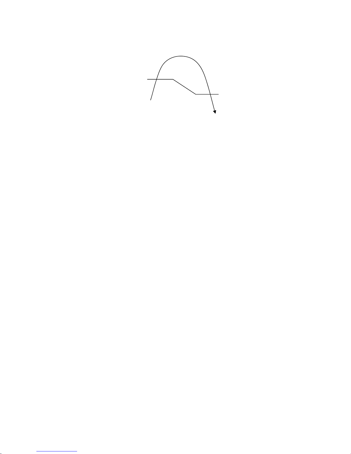
95
13.10 Outdoor Air Temperature Control
• The compressor operating frequency is regulated in accordance to the outdoor air temperature as shown in the
diagram below.
• This control will begin 1 minute after the compressor starts.
• Compressor frequency will adjust based on outdoor air temperature.
13.11 Cooling Overload Control
• Pipe temperature limitation / restriction.
o Detects the outdoor pipe temperature and carry out restriction / limitation below (Limit the compressor
operation frequency)
o The compressor stops if outdoor pipe temperature exceeds 61°C (S10, 15PK), 63°C (S13, 18, 24PK).
o If the compressor stops 4 times in 20 minutes, Timer LED blinks (“F95” indicated: Outdoor high pressure rise
protection)
13.12 Freeze Prevention Control 1
• When indoor hear exchanger temperature is lower than 0°C continuously for 6 minutes, compressor will stops
operation.
• Compressor will resume its operation 3 minutes after the indoor heat exchanger is higher than 5°C.
• At the same time, indoor fan speed will be higher than during its normal operation.
• If indoor heat exchanger is higher than 5°C for 5 minutes, the fan speed will return to its normal operation.
13.13 Freeze Prevention Control 2
• Control start conditions
o During Cooling operation and soft dry operation
During thermo OFF condition, indoor intake temperature is less than 10°C or
Compressor stops for freeze prevention control
o Either one of the conditions above occurs 5 times in 60 minutes.
• Control contents
o Operation stops
o Timer LED blinks and “H99” indicated
13.14 Dew Prevention Control
• To prevent dew formation at indoor unit discharge area.
• This control will be activated if:
o Outdoor air temperature and indoor pipe temperature judgment by microcontroller is fulfilled.
o When COOL or DRY mode is operated more than 20 minutes or more.
• This control stopped if
o Compressor stopped.
o Remote Control setting changed (fan speed/ temperature).
o Outdoor air temperature and indoor intake temperature changed.
• Fan speed will be adjusted accordingly in this control.
Free
Limited Frequency
Outdoor air temperature
38°C
37°C
Page 96

96
13.15 Odor Cut Control
• To reduce the odor released from the unit.
o Start Condition
AUTO FAN Speed is selected during COOL or DRY operation.
During freeze prevention control and timer preliminary operation, this control is not applicable.
o Control content
Depends on compressor conditions:
1. Compressor OFF → Compressor ON.
The indoor unit fan stops temporarily and then starts to blow at minimum airflow for 30 seconds.
2. Compressor ON → Compressor OFF.
The indoor unit fan stops for 90 seconds and then blows at minimum airflow for 20 seconds.
Page 97
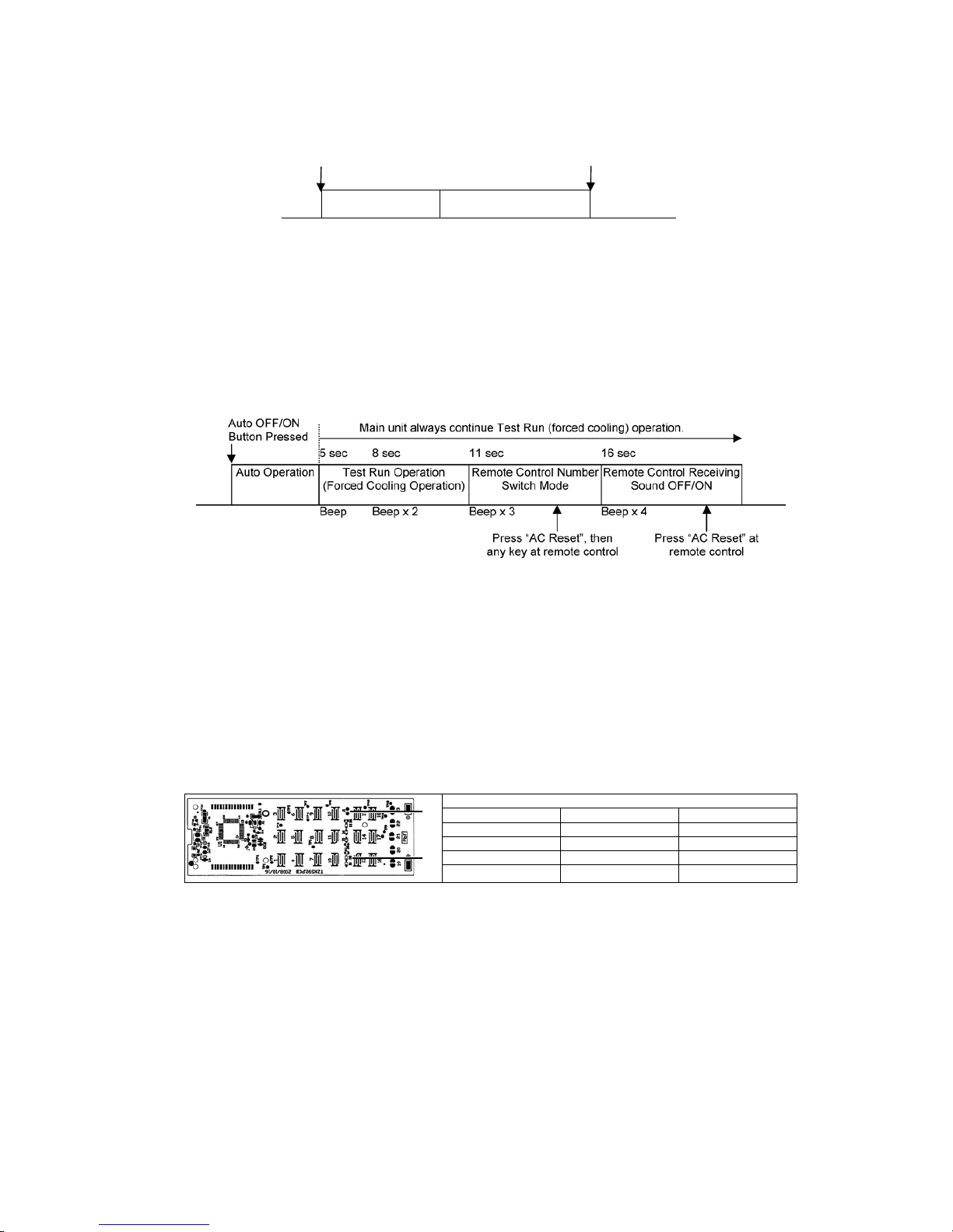
97
14. Servicing Mode
14.1 Auto Off/On Button
Auto OFF/ON
Button Pressed
Auto OFF/ON
Button Pressed
5 sec
Auto Operation Test Run Operation
(Forced Cooling Operation)
Stop
Beep
1 AUTO OPERATION MODE
The Auto Operation will be activated immediately once the Auto OFF/ON button is pressed. This operation
can be used to operate air conditioner with limited function if remote control is misplaced or malfunction.
2 TEST RUN OPERATION (FOR PUMP DOWN/SERVICING PURPOSE)
The Test Run Operation will be activated if the Auto OFF/ON button is pressed continuously for more than 5
seconds. A “beep” sound will be heard at the fifth seconds, in order to identify the starting of this operation.
The Auto OFF/ON button may be used together with remote control to set / change the advance setting of air
conditioner operation.
3 REMOTE CONTROL NUMBER SWITCH MODE
The Remote Control Number Switch Mode will be activated if the Auto OFF/ON button is pressed
continuously for more than 11 seconds (3 “beep” sounds will occur at 11
th
seconds to identify the Remote
Control Number Switch Mode is in standby condition), press “AC Reset” button and then press any button at
remote control to transmit and store the desired transmission code to the EEPROM.
There are 4 types of remote control transmission code could be selected. The indoor unit will only operate
when received signal with same transmission code from remote control. This could prevent signal
interference when there are 2 or more units installed nearby together.
To change remote control transmission code, short or open jumpers at the remote control printed circuit
board.
Remote Control Printed Circuit Board
Jumper A (J1) Jumper B (D2) Remote Control No.
Short Open A (Default)
Open (cut jumper) Open B
Short Short with diode C
Open (cut jumper) Short with diode D
* Diode is field supplied. Part number: SOD-323 IN4148WS / LMDL914T1G
4 REMOTE CONTROL RECEIVING SOUND OFF/ON MODE
The Remote Control Receiving Sound OFF/ON Mode will be activated if the Auto OFF/ON button is pressed
continuously for more than 16 seconds (4 “beep” sounds will occur at 16
th
seconds to identify the Remote
Control Receiving Sound OFF/ON Mode is in standby condition) and press “AC Reset” button at remote
control.
Press Auto OFF/ON button to toggle remote control receiving sound.
- Short “beep”: Turn OFF remote control receiving sound.
- Long “beep”: Turn ON remote control receiving sound.
After Auto OFF/ON button is pressed, the 20 seconds counter for Remote Control Receiving Sound OFF/ON
Mode is restarted.
D2
J1
Page 98

98
14.2 Remote Control Button
14.2.1 SET Button
• To check remote control transmission code and store the transmission code to EEPROM
o Press “Set” button continuously for 10 seconds by using pointer
o Press “Timer Set” button unit a “beep” sound is heard as confirmation of transmission code change.
o Confirm setting by pressing “Timer Set” button, a “beep” sound will be heard. LCD returns to original display
after 2 seconds.
o LCD returns to original display if remote control does not operate for 30 seconds.
14.2.2 RESET (RC)
• To clear and restore the remote control setting to factory default.
o Press once to clear the memory
14.2.3 RESET (AC)
• To restore the unit’s setting to factory default.
o Press once to restore the unit’s setting
14.2.4 TIMER ▲
• To change indoor unit indicators’ intensity:
o Press continuously for 5 seconds.
14.2.5 TIMER ▼
• To change remote control display from Degree Celsius (°C) to Degree Fahrenheit (°F)
o Press continuously for 10 seconds.
Page 99
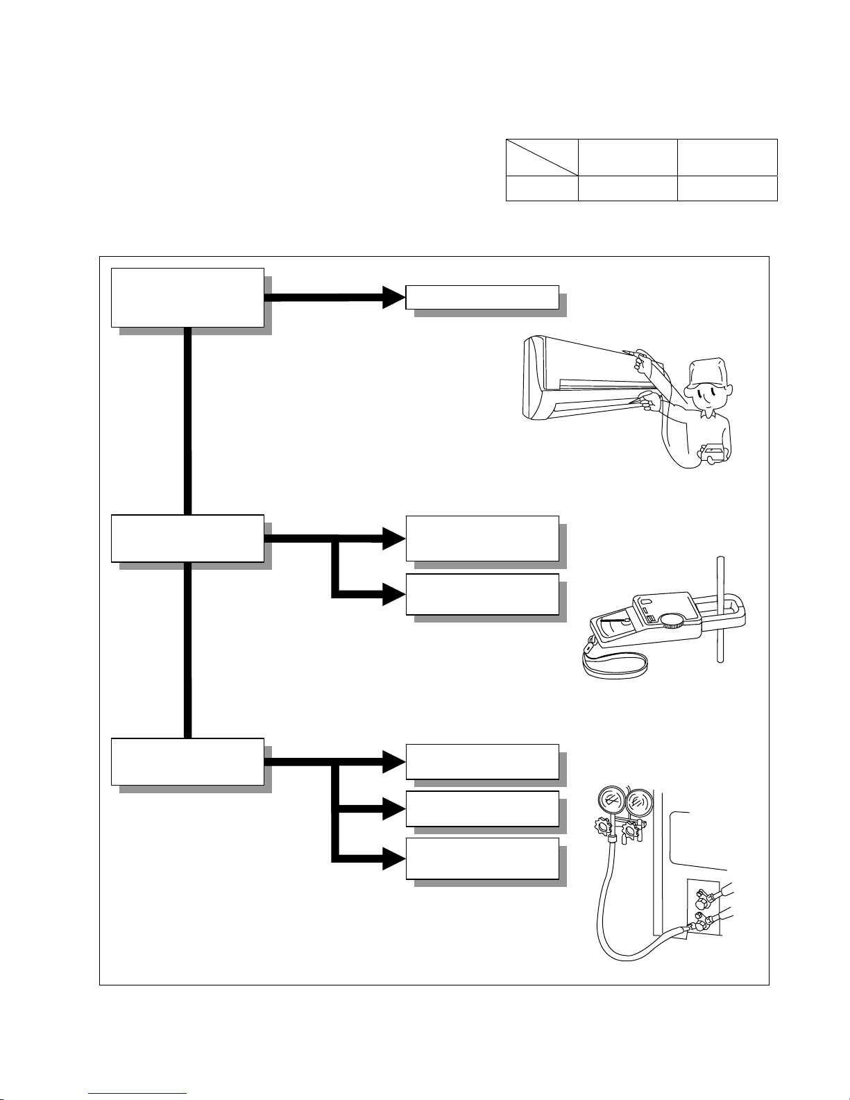
99
15. Troubleshooting Guide
15.1 Refrigeration Cycle System
In order to diagnose malfunctions, ensure the air conditioner is free
from electrical problems before inspecting the refrigeration cycle.
Such problems include insufficient insulation, problem with the
power source, malfunction of a compressor and a fan. The normal
outlet air temperature and pressure of the refrigeration cycle
depends on various conditions, the standard values for them are
shown in the table to the right.
Normal Pressure and Outlet Air Temperature (Standard)
Gas Pressure
Mpa
(kg/cm
2
G)
Outlet air
Temperature
(°C)
Cooling Mode 0.9 ~ 1.2 (9 ~ 12) 12 ~ 16
Condition: Indoor fan speed = High
Outdoor temperature = 35°C at cooling mode.
Compressor operate at rated frequency
Different in the intake
and outlet
air temperatures
Normal
Value of electric current
during operation
Dusty condenser
preventing heat radiation
Excessive amount
of refrigerant
Gas side
pressure
Inefficient compressor
Insufficient refrigerant
Clogged strainer or
capillary cube
•
Measuring the air
temperature different
•
Measuring electric current
during operation
•
Measuring gas side
pressure
More than 8°C
(15 minutes after an
operation is started) at
cooling mode.
Less than 8°C at the cooling mode
Higher than specified
Cooling
Mode
High
Low
Low
Lower than specified
Page 100
100
15.1.1 Relationship between the condition of the air conditioner and pressure and
electric current
Cooling Mode
Condition of the
air conditioner
Low Pressure High Pressure Electric current during operation
Insufficient refrigerant
(gas leakage)
Ô Ô Ô
Clogged capillary tube or
strainer
Ô Ô Ô
Short circuit in the indoor unit
Ô Ô Ô
Heat radiation deficiency
of the outdoor unit
Ò Ò Ò
Inefficient compression
Ò Ô Ô
• Carry out the measurement of pressure, electric current, and temperature fifteen minutes after an operation is started.
 Loading...