

Page 1
CR
SPECIFICATIONS
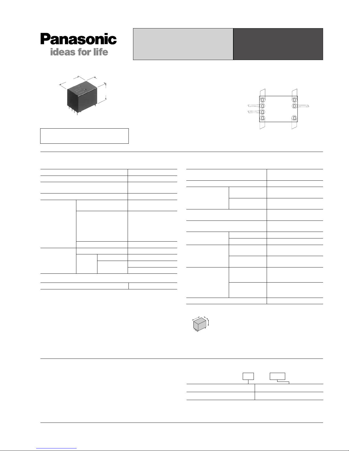
TWIN POWER SILENT
AUTOMOTIVE RELAY
CR RELAYS
18.5
.728
24.6
.969
17.0
.669
mm inch
RoHS Directive compatibility information
http://www.nais-e.com/
FEATURES
• Silent
Noise has been reduced by
approximately 20 dB, using our own
silencing design.
• Twin (1 Form C × 2)
Forward/reverse motor control is possible
with a single relay.
• Sealed construction
• Simple footprint enable ease of PC
board layout
Normally
Open
Common
Normally
Closed
Coil
Coil
Contact
Coil
#1 This value can change due to the switching frequency, environmental conditions,
and desired reliability level, therefore it is recommended to check this with the
actual load.
Characteristics
Arrangement 1 Form C × 2
Contact material Ag alloy (Cadmium free)
Initial contact resistance (Initial)
(By voltage drop 6 V DC 1A)
Typ. 6 mΩ (N.O.)
Typ. 9 mΩ (N.C.)
Contact voltage drop Max. 0.2V (at 10 A)
Rating
Nominal switching
capacity
N.O.: 20 A 14 V DC
N.C.: 10 A 14 V DC
Max. carrying current
35 A for 2 minutes,
25 A for 1 hour
(12 V, at 20°C68°F)
30 A for 2 minutes,
20 A for 1 hour
(12 V, at 85°C185°F)
Min. switching capacity
#1
1 A 12 V DC
Expected life
(min. operations)
Mechanical (at 120 cpm) Min. 10
7
Electrical
Resistive load Min. 10
5*1
Motor load
Min. 2×105*
2
Min. 105*
3
Nominal operating power 640 mW
Max. operating speed
(at nominal switching capacity)
6 cpm
Initial insulation resistance*
4
Min. 100 MΩ (at 500 V DC)
Initial breakdown
voltage*
5
Between open
contacts
500 Vrms for 1 min.
Between contacts
and coil
500 Vrms for 1 min.
Operate time*6
(at nominal voltage)(at 20°C68°F)
Max. 10 ms (initial)
Release time*6
(at nominal voltage)(at 20°C68°F)
Max. 10 ms (initial)
Shock resistance
Functional*
7
Min. 100 m/s2 {10G}
Destructive*
8
Min. 1,000 m/s2 {100G}
Vibration resistance
Functional*
9
10 Hz to 100 Hz,
Min. 44.1 m/s2 {4.5G}
Destructive*
10
10 Hz to 500 Hz,
Min. 44.1 m/s
2
{4.5G}
Conditions for
operation, transport
and storage*11
(Not freezing and
condensing at low
temperature)
Ambient
temperature
–40°C to +85°C
–40°F to +185°F
Humidity 5% R.H. to 85% R.H.
Mass Approx. 12.5g.44 oz
Remarks
*1At nominal switching capacity, operating frequency: 1s ON, 9s OFF
*
2
N.O.: at 5 A (steady), 25 A (inrush)/N.C.: at 20 A (brake) 14 V DC, operating
frequency: 0.5s ON, 9.5s OFF
*
3
At 20A 14 V DC (Motor lock), operating frequency: 0.5s ON, 9.5s OFF
*
4
Measurement at same location as “Initial breakdown voltage” section
*
5
Detection current: 10mA
*
6
Excluding contact bounce time
*
7
Half-wave pulse of sine wave: 11ms; detection: 10µs
*
8
Half-wave pulse of sine wave: 6ms
*
9
Detection time: 10µs
*10Time of vibration for each direction;
X, Y, direction: 2 hours
Z direction: 4 hours
*
11
Refer to Conditions for operation, transport and storage mentioned in AMBIENT
ENVIRONMENT.
Please inquire if you will be using the relay in a high temperature atmosphere
(110°C 230°F).
X
Y
Z
TYPICAL APPLICATIONS
• Power windows
• Auto door lock
• Electrically powered sunroof
• Electrically powered mirror, etc.
ORDERING INFORMATION
Contact arrangement Coil voltage(DC)
1 Form C × 2
Standard packing: Carton(tube package) 32pcs. Case: 800pcs.
12 V
Ex. CR 2 12 V–
All Rights Reserved © COPYRIGHT Matsushita Electric Works, Ltd.
Page 2
CR
TYPES AND COIL DATA (at 20°C 68°F)
* Other pick-up voltage types are also available. Please contact us for details.
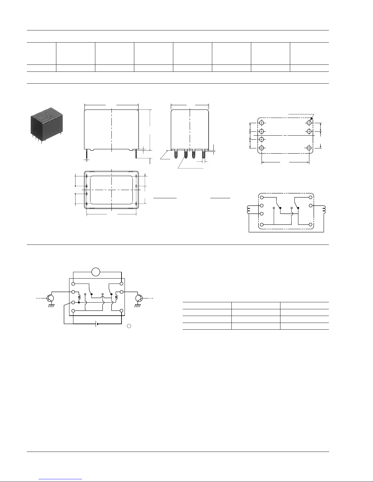
DIMENSIONS
mm inch
EXAMPLE OF CIRCUIT
Part No.
Nominal voltage,
V DC
Pick-up voltage,
V DC
(Initial)*
Drop-out voltage,
V DC
(Initial)
Coil resistance,
Ω
Nominal
operating
current,
mA
Nominal
operating power,
mW
Usable voltage
range,
V DC
CR2-12V 12 Max. 7.2 Min. 1.0 225±10% 53.3±10% 640 10 to 16
4.5
.177
3.5
.138
4.5
.177
0.6
.024
7-0.25
.010
7-1.2
.047
3.5
.138
18.5
.728
24.6
.969
17.0
.669
22.4
.882
8.0
.315
4.5
.177
Pre-soldering
A*
Max.
1.0
.039
Dimension: Tolerance
Max. 1mm .039 inch: ±0.1 ±.004
1 to 3mm .039 to .118 inch: ±0.2 ±.008
Min. 3mm .118 inch: ±0.3 ±.012
* Dimensions (thickness and width) of terminal specified in this catalog is measured before pre-soldering.
Intervals between terminals is measured at A surface level.
PC board pattern (Bottom view)
Tolerance: ±0.1 ±.004
Schematic (Bottom view)
4.5
.177
4.5
.177
4.5
.177
3.5
.138
7-1.5 dia
7-.059 dia
+0.1
0
+.004
0
22.4
.882
8.0
.315
COM1 COM2
COIL
NCNO
Forward/reverse control circuits of DC motor for power window
M
Power window motor
COM COM
12 VDC
NC
NO
Tr1 Tr2
M
Tr1 Tr2 Motor
OFF OFF Stop
ON OFF Forward
OFF ON Reverse
All Rights Reserved © COPYRIGHT Matsushita Electric Works, Ltd.
Page 3
CR
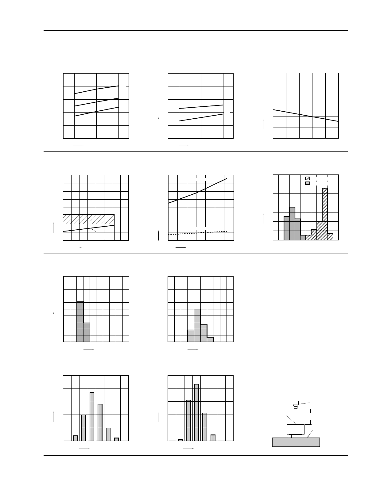
REFERENCE DATA
1-(1). Coil temperature rise (at room
temperature)
Sample: CR2-12V, 5pcs
Contact carrying current: 10A, 15A, 20A
Ambient temperature: Room temperature
1-(2). Coil temperature rise (at 85°C 185°F)
Sample: CR2-12V, 5pcs
Contact carrying current: 10A, 15A
Ambient temperature: 85°C 185°F
2. Max. switching capability (Resistive load,
initial)
12 14 16
200
160
120
80
40
0
15A
10A
20A
Coil applied voltage, V
Temperature rise, °C
12 14 16
200
160
120
80
40
0
15A
10A
Coil applied voltage, V
Temperature rise, °C
0
Switching current, A
Switching voltage, VDC
10
50
40
30
20
60
(N.O. side Room temperature)
020304010 50
3. Ambient temperature and operating
temperature range
4. Ambient temperature characteristics 5. Distribution of pick-up and drop-out voltage
Sample: CR2-12V, 100pcs
0
Ambient temperature, °C
Coil applied voltage, VDC
5
10
15
35
30
25
20
40
–40 –20 20 40 60 1000 120
8085
Pick-up voltage
(Cold start)
0
Ambient temperature, °C
Ratio against the rated voltage, %V
10
20
30
70
60
50
40
80
–40 –20 20 40 60 1000
Pick-up voltage upper limit
Pick-up voltage lower limit
80
0
30
20
10
40
50
60
70
Voltage, V
Frequency, n
1.5 2.0 2.5 3.0 3.5 4.5 5.04.0 5.5 6.0 6.5 7.0 7.5
Pick-up voltage
Drop-out voltage
6. Distribution of operate time
Sample: CR2-12V, 100pcs
7. Distribution of release time
Sample: CR2-12V, 100pcs
* With diode
0
30
20
10
40
50
60
70
80
90
100
Time, ms
Quantity, n
3.02.01.5 2.5 3.5 4.5 5.04.0 5.5 6.0 6.5
0
30
20
10
40
50
60
70
80
90
100
Time, ms
Quantity, n
3.02.01.5 2.5 3.5 4.5 5.04.0 5.5 6.0 6.5
8-(1). Operation noise distribution
When operated
8-(2). Operation noise distribution
When released
Measuring conditions
Sample: CR2-12 V, 50 pcs.
Equipment setting: “A” weighted, Fast, Max. hold
Coil voltage: 12V DC
Coil connection device: Diode
Background noise: Approx. 20dB
0
10
20
30
40
50
40 42 44 46 48 50 52 5654
Frequency
Noise level, dB
0
10
30
20
40
50
36 38 40 42 4644 48 50 52
Frequency
Noise level, dB
Relay
Microphone
Sponge
50mm
1.969inch
All Rights Reserved © COPYRIGHT Matsushita Electric Works, Ltd.
Page 4
CR
For Cautions for Use, see Relay Technical Information.
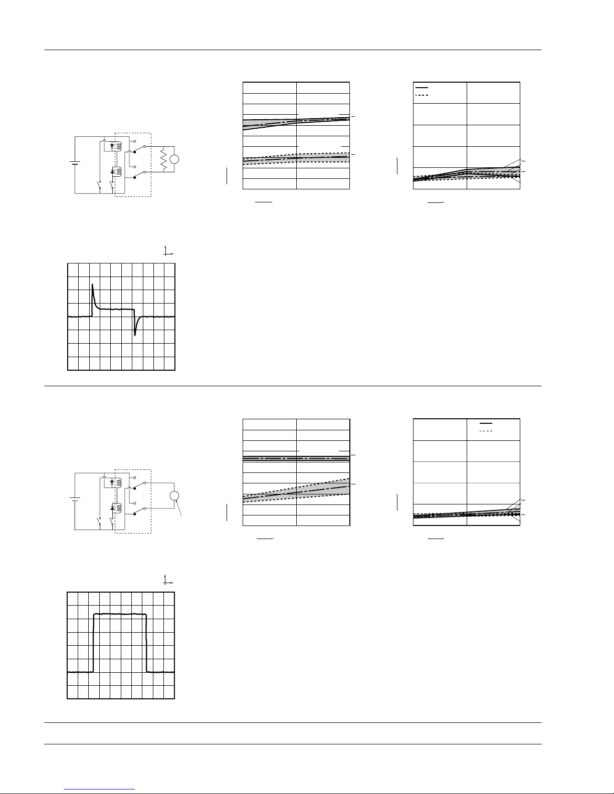
9-(1). Electrical life test (Motor free)
Sample: CR2-12V, 3pcs
Load: Inrush current: 25A, Steady current: 6A,
Brake current: 15A,
power window motor actual load (free condition)
Tested voltage: 14V DC
Ambient temperature: Room temperature
Circuit
Change of pick-up and drop-out voltage Change of contact resistance
14VDC
M
0
No. of operations, × 10
4
Pick-up and drop-out voltage, V
Max.
Max.
Min.
Min.
X
X
2
1
4
6
8
9
7
5
3
10
02010
Pick-up voltage
Drop-out voltage
Max.
Min.
X(N.C.)
0
No. of operations, × 10
4
Contact resistance, mΩ
Max.
Min.
X(N.O.)
50
40
30
20
10
010
N.O. side
N.C. side
Load current waveform
Inrush current: 25A, Steady current: 6A,
Brake current: 15A
Tested voltage: 14V DC
100ms
10A
9-(2). Electrical life test (Motor lock)
Sample: CR2-12V, 3pcs
Brake current: 22A,
power window motor actual load (lock condition)
Tested voltage: 14V DC
Switching frequency: (ON:OFF = 0.5s:9.5s)
Ambient temperature: Room temperature
Circuit
Change of pick-up and drop-out voltage Change of contact resistance
14VDC
Motor
M
0
No. of operations, × 10
4
Pick-up and drop-out voltage, V
Max.
Max.
Min.
Min.
X
X
2
1
4
6
8
9
7
5
3
10
0105
Pick-up voltage
Drop-out voltage
0
No. of operations, × 10
4
Contact resistance, mΩ
Max.
Min.
X
10
20
30
40
50
0105
Max.
Min.
X
N.O. side
N.C. side
Load current waveform
Brake current: 22A
Tested voltage: 14V DC
100ms
5A
All Rights Reserved © COPYRIGHT Matsushita Electric Works, Ltd.
 Loading...