

Page 1
CD Player/Receiver with Changer Control
CQ-DF501/DF301W
(CQ-DF501W)
VOL
S
C
A
N
A
U
T
O
•
P
SEL
BAND
TUNE
MUTE DISP
12
34
5
6
712
C
L
O
C
K
SOURCE
REP
CQ-DF501W
CD RECEIVER WITH CHANGER CONTROL
MOSFET
45WX4
RANDOM
OPEN
PWR
811
910
TRACK
S•HDB
M
O
N
O
/L
O
C
LEVL
REMOTE
DIMMER
≥Please read these instructions carefully before using this product and save this manual for future use.
Operating Instructions
Page 2
CQ-DF501/DF301W
9
E
N
G
L
I
S
H
CQ-DF501/DF301W
8
E
N
G
L
I
S
H
❐ Use this Product Safely
Panasonic welcomes you to our ever growing family of electronic product owners. We know that this product will bring you many hours of enjoyment. Our reputation is built on precise electronic and mechanical
engineering, manufactured with carefully selected components and assembled by people who take pride in
their work. Once you discover the quality, reliability, and value we have built into this product, you too will
be proud to be a member of our family.
When Driving
Keep the volume level low enough to be aware of
road and traffic conditions.
When Car Washing
Do not expose the product, including the speakers
and CDs, to water or excessive moisture. This
could cause electrical shorts, fire, or other damage.
When Parked
Parking in direct sunlight can produce very high
temperatures inside your car. Give the interior a
chance to cool down before switching the unit on.
Use the Proper Power Supply
This product is designed to operate with a 12 V DC,
negative ground battery system.
Disc Mechanism
Do not insert coins or any small objects. Keep
screwdrivers and other metallic objects away from
the disc mechanism and disc.
Use Authorized Servicenters
Do not attempt to disassemble or adjust this precision product. Please refer to the Servicenter list including with this product for service assistance.
For Installation
This product should be installed in a horizontal position with the front end up at a convenient angle,
but not more than 30x.
Note:
≥This operating instruction manual is for 2 models CQ-DF501W and CQ-DF301W. All illustrations through-
out this manual represent model CQ-DF501W unless otherwise specified. The following table describes
the differences between 2 models.
≥Operating instructions .................................... 1
≥Installation hardware................1 set (➡ page 19)
≥Power connector ............................................ 1
≥Remote control unit ........................................ 1
≥Lithium battery (CR2025)................................ 1
≥Warranty card.................................................. 1
❐ Components
Models
Features
CQ-DF501W CQ-DF301W
S•HDB Yes None
Loudness control None Yes
Pre-Amp output level 4 V 2 V
Subwoofer output level 4 V 2 V
LCD color 3 colors Blue
Page 3

VOL
SEL
BAND
TUNE
MUTE DISP
12
34
5
6
712
CLOCK
SOURCE
PWR
REP
CQ-DF501W
CD RECEIVER WITH CHANGER CONTROL
MOSFET
45WX4
RANDOM
OPEN
811
910
TRACK
S•HDB
M
O
N
O
/LO
C
LEVL
REMOTE
DIMMER
SCAN
AUTO
•
P
E
N
G
L
I
S
H
CQ-DF501/DF301W
11
E
N
G
L
I
S
H
1
CQ-DF501/DF301W
10
Power
Turn the key in the ignition until the accessory indicator lights.
Power on: Press [SOURCE] (PWR).
Power off: Press [SOURCE] (PWR) again and hold.
E
N
G
L
I
S
H
2
Loudness
Press [LOUD] to enhance bass and treble tones
at low or medium volume.
Press [LOUD] again to cancel.
Dimmer
Press and hold [LEVL] (DIMMER) for more than
2 seconds to change the dimmer level.
Level Meter
When the power is on, the level of sound sources,
such as radio and CD, is displayed.
Press [LEVL] to change the level meter display.
VOL
SEL
BAND
TUNE
MUTE DISP
12
34
5
6
712
CLOCK
SOURCE
REP
CQ-DF501W
CD RECEIVER WITH CHANGER CONTROL
MOSFET
45WX4
RANDOM
OPEN
811
910
TRACK
S•HDB
M
O
N
O
/LO
C
LEVL
REMOTE
DIMMER
SCAN
AUTO
•
P
PWR
Dimmer 1 Dimmer 2 Dimmer 3
(Bright) (Medium) (Dark)
(Default)
Pattern 1 Pattern 2 Pattern 3
Pattern 4Pattern 5Pattern off
(Default)
LOUD
S•HDB
(Super High Definition Bass)
Especially for rock music, the bass-sound will be
more powerful.
Press [S•HDB] to change the Super High Definition
Bass on.
The bass sounds of the
speakers are strongly emphasized.
The bass sounds of the
speakers are moderately emphasized.
(The sounds of the subwoofer
can be heard clearly.)
Regular Mode
Boom
(S•HDB on) (S•HDB on)
Tight
Power and Sound Controls
Mute
Press [
MUTE
] to mute the sound completely.
Press [
MUTE
] again to cancel.
Note:
≥When the power is switched on for the first time,
a demonstration message appears on the display.
To cancel this display, press [DISP].
Volume
[" VOL]: Up
[# VOL]: Down
Press and hold for rapid adjustment.
Volume level
(0 to 40)
Anti-volume-blast circuit:
When the power is switched off and on again, the volume slowly rises to the previous level.
The anti-volume-blast circuit will not work when the volume level is set lower than position 20 on the display.
A
CC
O
N
Only for CQ-DF501W
Only for CQ-DF301W
Page 4
VOL
SEL
BAND
TUNE
MUTE DISP
12
34
5
6
712
CLOCK
SOURCE
REP
CQ-DF501W
CD RECEIVER WITH CHANGER CONTROL
MOSFET
45WX4
RANDOM
OPEN
811
910
TRACK
S•HDB
M
O
N
O
/LO
C
LEVL
REMOTE
DIMMER
SCAN
AUTO
•
P
PWR
E
N
G
L
I
S
H
CQ-DF501/DF301W
13
E
N
G
L
I
S
H
3
CQ-DF501/DF301W
12
Power and Sound Controls (Continued)
E
N
G
L
I
S
H
4
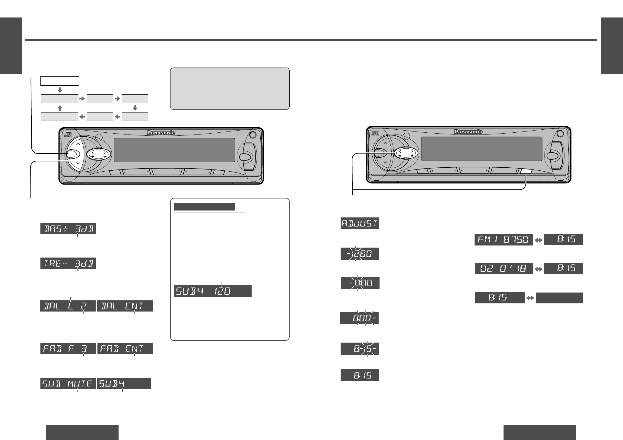
Initial Time
1 Press [DISP](CLOCK).
Hours
2 Press and hold [DISP](CLOCK).
3 Press [% TUNE]or [$ TUNE].
Minutes
4 Press [DISP](CLOCK).
5 Press [% TUNE]or [$ TUNE].
6 Press [DISP](CLOCK).
Note:
≥Press and hold [% TUNE] or [$ TUNE] to change
numbers rapidly.
Time Reset
Press and hold [DISP] (CLOCK) for more than
2 seconds to activate the time setting mode to reset
the time.
Then, repeat steps 3to 6.
Clock Display
Press [DISP] (CLOCK) to switch to the clock display.
Broadcast station
Clock display
Playing time Clock display
In CD player (changer) mode:
In tuner mode:
When the power is off:
No displayClock display
(Hours blink.)
(Hours set.)
(Minutes blink.)
(Minutes set.)
(End.)
Note:
≥The [DISP] (CLOCK) button will not work while
the CD player or CD changer is set to the scan
play mode. Cancel the scan play mode before
pressing [DISP] (CLOCK).
The 12-hour system is used for the clock.
VOL
SEL
BAND
TUNE
MUTE DISP
12
34
5
6
712
CLOCK
SOURCE
REP
CQ-DF501W
CD RECEIVER WITH CHANGER CONTROL
MOSFET
45WX4
RANDOM
OPEN
811
910
TRACK
S•HDB
M
O
N
O
/LO
C
LEVL
REMOTE
DIMMER
SCAN
AUTO
•
P
PWR
Clock Basics
Audio Mode (Bass/Treble/Balance/Fader/Subwoofer)
Regular Mode
Volume Bass Treble
BalanceFaderSubwoofer
Subwoofer volume:
Bass:
Adjustable range: j12 dB to i12 dB
Treble:
Adjustable range: j12 dB to i12 dB
Balance:
R (right speaker) or L (left speaker)
Fader:
F (front speaker) or R (rear speaker)
Adjustable range: 1 to 15 Balance center
Adjustable range: 1 to 15 Fader center
Subwoofer volume level:
From MUTE (0) to 8
Default
The maximum lower frequency level can be adjusted to match your subwoofer and the
acoustics inside your car.
When the subwoofer is activated, press
[% TUNE] or [$ TUNE] to change the cut-off
frequency as follows.
Cut-off frequency control
Cut-off frequency:
120 Hz/80 Hz (Default: 120 Hz)
Note:
≥Cut-off frequency control is not available for
CQ-DF301W (subwoofer volume can be adjusted).
Press [SEL] to select the audio mode.
Note:
≥If no operation takes place for more than
5 seconds in audio mode (2 seconds in volume mode), the display returns to the regular mode.
Press [" VOL] or [# VOL] to change each
level.
1
2
Only for CQ-DF501W
Page 5
VOL
SEL
BAND
TUNE
MUTE DISP
12
34
5
6
712
CLOCK
SOURCE
REP
CQ-DF501W
CD RECEIVER WITH CHANGER CONTROL
MOSFET
45WX4
RANDOM
OPEN
811
910
TRACK
S•HDB
M
O
N
O
/LO
C
LEVL
REMOTE
DIMMER
SCAN
AUTO
•
P
PWR
VOL
SEL
BAND
TUNE
MUTE DISP
12
34
5
6
712
CLOCK
SOURCE
REP
CQ-DF501W
CD RECEIVER WITH CHANGER CONTROL
MOSFET
45WX4
RANDOM
OPEN
811
910
TRACK
S•HDB
M
O
N
O
/LO
C
LEVL
ST
REMOTE
DIMMER
SCAN
AUTO
•
P
PWR
E
N
G
L
I
S
H
CQ-DF501/DF301W
15
E
N
G
L
I
S
H
5
CQ-DF501/DF301W
14
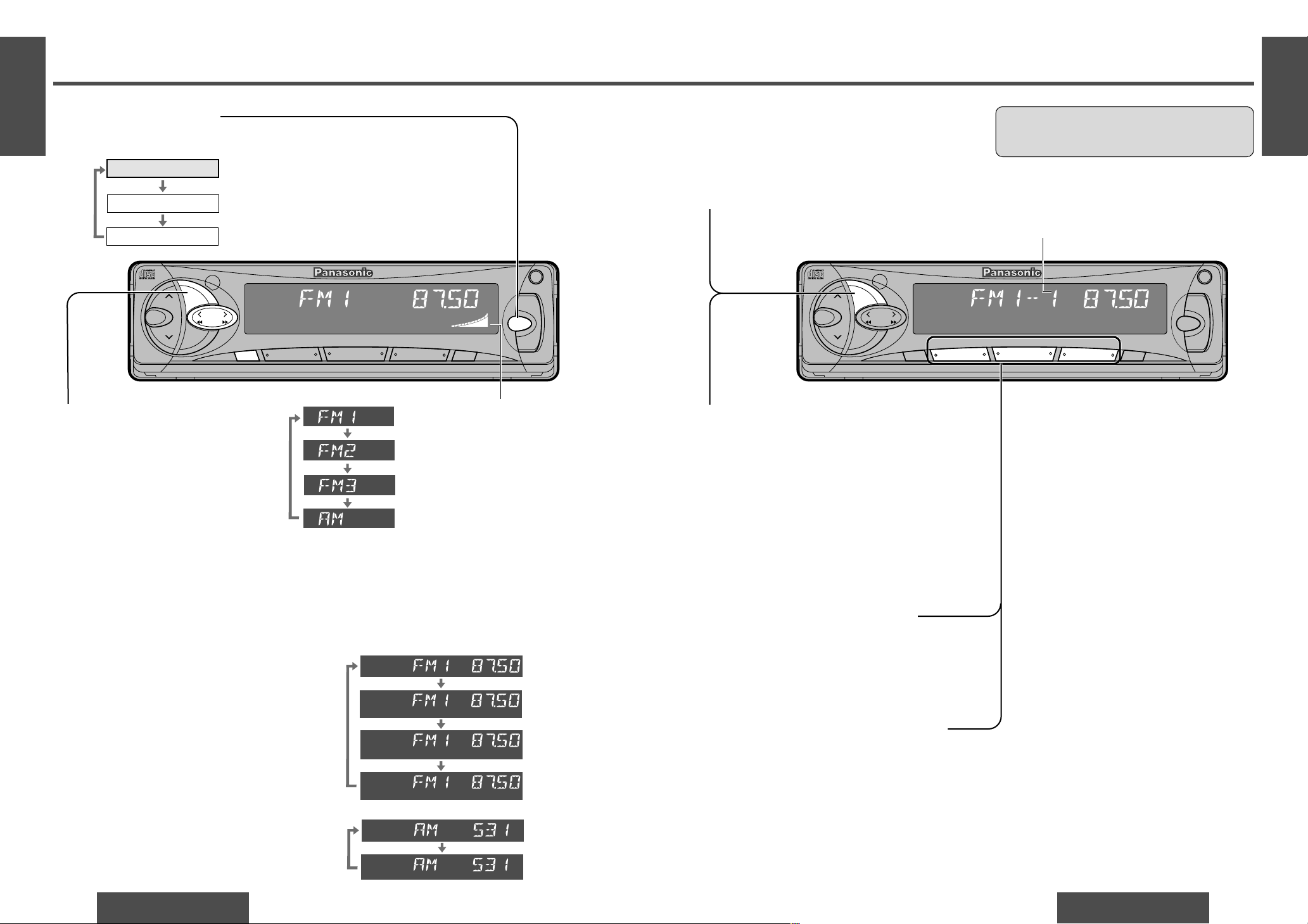
Radio Basics
E
N
G
L
I
S
H
6
Up to 6 stations each can be saved in the FM1,
FM2, FM3 and AM preset station memories.
Tuning in a Preset Station
Press the corresponding preset button [1]
to [6] to tune in a preset station.
Note:
≥You can change the memory presetting by re-
peating the above procedure.
Caution:
≥To ensure safety, never attempt to preset sta-
tions while you are driving.
Preset number
3
Manual Station Preset
1 Use manual or seek tuning to find a
station. (➡ page 14)
2 Press and hold one of the preset but-
tons [1] to [6] until the display blinks
once.
Preset Station Setting
Band
Press [BAND] to select a desired band.
(➡ page 14)
Auto Station Preset
Press and hold [BAND] (AUTO•P) for
more than 2 seconds (auto preset memory).
≥The 6 strongest available stations will be
automatically saved in the memory
under preset buttons [1] to [6].
≥Once set, the preset stations are se-
quentially scanned for 5 seconds each.
Note:
≥The stations manually preset on the se-
lected band will be deleted.
Radio
CD player
CD changer control
(When a CD is inserted.)
(When a CD changer is connected.)
Source
FM stereo indicator
MONO
LOCAL
MONO
LOCAL
LOCAL
MONO OFF/
LOCAL OFF
MONO ON/
LOCAL OFF
MONO ON/
LOCAL ON
MONO OFF/
LOCAL ON
LOCAL OFF
LOCAL ON
FM broadcast:
AM broadcast:
Seek Tuning
Press and hold ...
[$ TUNE]: Higher frequency
[% TUNE]: Lower frequency
Tuning will automatically stop when the signals
of the next broadcast station are received.
Band
Press [BAND] to change the band.
Mode Selection
Press [SOURCE] to change to the radio mode.
Manual Tuning
[$ TUNE]: Higher frequency
[% TUNE]: Lower frequency
Mono/Local Selection
MONO: Noise is significantly decreased when
weak signals are received from an FM
broadcast station.
LOCAL: Only strong signals of stations are
searched in seek tuning, while at the
LOCAL OFF setting, relatively weak signals are also searched.
FM broadcast:
Press and hold [MUTE] (MONO/LOC) to change
the mode.
Release when at the desired mode.
AM broadcast:
Press and hold [MUTE] (MONO/LOC) to switch
LOCAL mode on and off.
1
2
3
4
1
2
Page 6
VOL
SEL
BAND
TUNE
MUTE DISP
12
34
5
6
712
CLOCK
SOURCE
REP
CQ-DF501W
CD RECEIVER WITH CHANGER CONTROL
MOSFET
45WX4
RANDOM
OPEN
811
910
TRACK
S•HDB
M
O
N
O
/LO
C
LEVL
REMOTE
DIMMER
SCAN
AUTO
•
P
PWR
VOL
SEL
BAND
TUNE
MUTE DISP
12
34
5
6
712
CLOCK
SOURCE
PWR
REP
CQ-DF501W
CD RECEIVER WITH CHANGER CONTROL
MOSFET
45WX4
RANDOM
OPEN
811
910
TRACK
S•HDB
MONO/LOC
LEVL
REMOTE
DIMMER
S
C
A
N
A
U
T
O
•
P
SOURCE
PWR
REP
MOSFET
45WX4
RANDOM
OPEN
E
N
G
L
I
S
H
CQ-DF501/DF301W
17
E
N
G
L
I
S
H
7
CQ-DF501/DF301W
16
CD Player and CD Changer
RAND
E
N
G
L
I
S
H
8
Track random play
≥ Press and hold [REP] (RANDOM) for
more than 2 seconds.
All the tracks (on all discs in the magazine*) are played in random order.
(*Only for CD changer)
≥ Press and hold [REP] (RANDOM) again
to cancel.
Track scan play
Disc scan play
≥ Press [BAND] (SCAN).
The first 10 seconds of each track on
the disc are played in sequence.
≥ Press [BAND] (SCAN) again to cancel.
Track repeat play
≥ Press [REP].
The current track is repeated.
≥ Press [REP] again to cancel.
≥ Press and hold [BAND] (SCAN) for
more than 2 seconds.
The first track of all the discs in the
magazine is played for 10 seconds
each.
≥ Press and hold [BAND] (SCAN) again to
cancel.
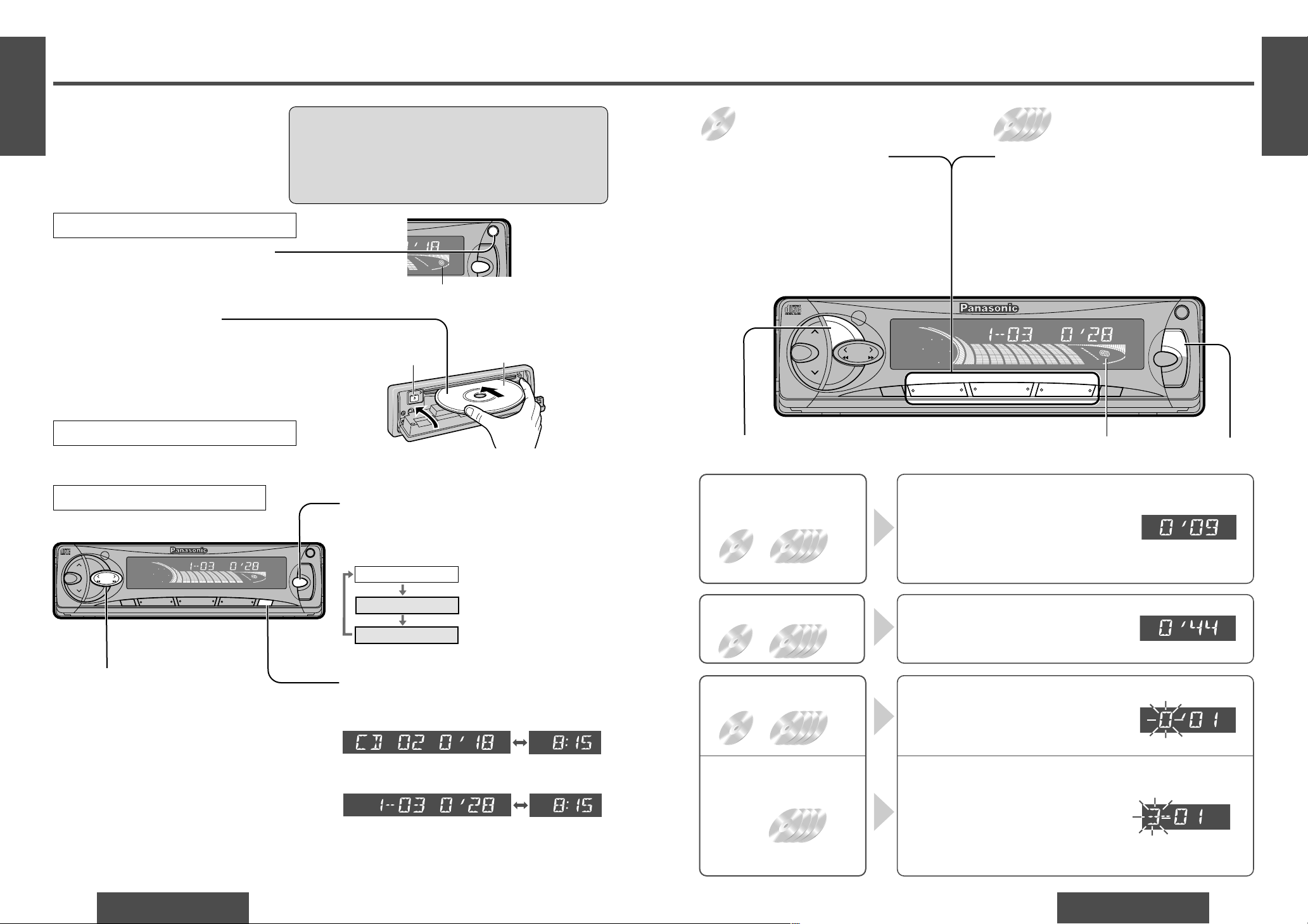
CD
player
CD
changer
CD
player
CD
changer
CD
changer
CD
player
CD
changer
Direct Track Selection
≥Press a track number button from [1] to
[6].
The corresponding track starts playing.
≥Press and hold a track number button from
[7] to [12] ([1] to [6]) for more than 1 second.
The corresponding track starts playing.
Direct Disc Selection
≥Press a disc number button from [1] to [6].
The corresponding disc starts playing.
≥Press and hold a disc number button from [7] to
[12] ([1] to [6]) for more than 1 second.
The corresponding disc starts playing.
Track scan play
Disc scan play
Track random play
Track repeat play
Lights when a magazine is
loaded in the changer.
CD
player
CD
changer
≥Lights when the disc is loaded.
≥Do not insert a disc when this indicator lights.
Note:
≥The CD changer functions are designed for
Panasonic CD changer unit (optional).
Display Change
Press [DISP] to switch to the clock display.
Radio
CD player
CD changer control
(When a CD is inserted.)
(When a CD changer is
connected.)
Source
Mode Selection
Press [SOURCE] to change to the CD player or
CD changer mode.
Track number/Track playing time
Listening to a CD
Disc number/Track number/
Track playing time
CD player:
CD changer:
Track Selection
[5TRACK]: Advance to the next track.
[6TRACK]: Back to the beginning of the cur-
rent track.
Back to the previous track.
(Press twice.)
Track Search
Press and hold ...
[5TRACK]: Fast forward
[6TRACK]: Fast backward
Release to resume the regular CD or CD changer
play.
<
(EJECT)
Press [<] (EJECT) to stop CD play and eject the disc.
Cautions:
≥Only 12 cm CD is available for this unit.
≥This unit is not designed for any 8 cm CD.
≥If you insert an 8 cm CD and can not eject it, turn ACC of
your car off once and turn it on again, then press [<]
(EJECT).
Label side
Close
Disc Insert and Playback
Stop and Disc Eject
Open the front panel.
Press [OPEN] to open the front panel.
Insert the disc.
Close the front panel manually.
Playback will start automatically.
1
2
When CD is in the player
Press [SOURCE] to change to CD play mode.
Clock display
Clock display
REP
Page 7
E
N
G
L
I
S
H
CQ-DF501/DF301W
19
Installation Guide
E
N
G
L
I
S
H
9
CQ-DF501/DF301W
18
Remote Control Unit Preparation
E
N
G
L
I
S
H
10
1
1
1
1
1
1
1
1
No. Item Diagram Q’ty
WARNING
This installation information is designed for experienced installers and is not intended for non-technical individuals. It does not contain warnings or cautions of potential dangers involved in attempting to install this product.
Any attempt to install this product in a motor car by anyone other than qualified in-
staller could cause damage to the electrical system and could result in serious personal injury or death.
❐ Installation Hardware
If you encounter problems, please consult your
nearest professional installer.
6
7
8
Mounting collar
Hex. nut (5 mm·)
Rear support strap
Tapping screw
(5 mm·a16 mm)
Mounting bolt (5 mm·)
Power connector
Removable face plate
case
Trim plate
1
2
3
4
5
❐ Overview
12 V DC
Test bulb
Electrical
tape
Side-cut
pliers
❐ Required Tools
You’ll need a screwdriver, a 1.5 V AA battery, and
the following:
❐ Dashboard Specifications
Thickness
Min. 4.75 mm
Max. 5.56 mm
53 mm
182 mm
This product should be installed by a professional.
However, if you plan to install this product yourself,
your first step is to decide where to install it. The
instructions in these pages will guide you through
the remaining steps:
(Please refer to the “WARNING” statement
above.)
≥Identify and label the car wires.
≥Connect the car wires to the wires of the power
connector.
≥Install the unit in the dashboard.
≥Check the operation of the unit.
Caution:
≥This unit operates with a 12 V DC negative
ground auto battery system only. Do not attempt to use it in any other system. Doing so
could cause serious damage.
Before you begin installation, look for the items
which are packed with your unit.
≥Warranty Card…Fill this out promptly.
≥Panasonic Servicenter for Service Directory
…Keep for future reference in case the product
needs servicing.
≥Installation Hardware…Needed for in-dash in-
stallation.
Battery Installation
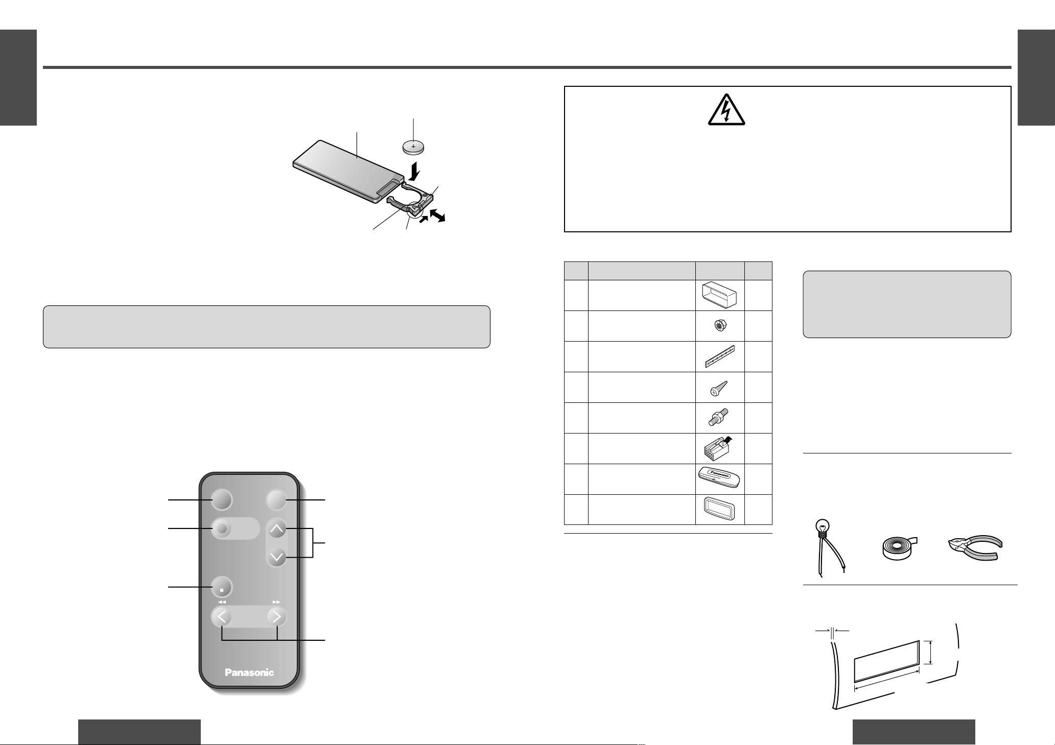
1 Remove the battery holder.
Pull the holder by the position B while pushing position A in the direction indicated by the arrow.
2 Install the battery on the battery holder.
Set a new battery properly with its (i) side facing up
as shown in the figure.
3 Insert the battery holder.
Push in the battery holder back into its original position.
Battery Notes
Remove and dispose of an old battery immediately.
Battery Information:
≥Battery type: Panasonic lithium battery (CR2025) (included)
≥Battery life: Approximately 6 months with normal use (at room temperature)
Back side
Lithium battery
(included)
Battery holder Position A
Position B
≥Do not disassemble or short the battery. Do not throw a battery into a fire.
≥Keep batteries away from children to avoid the risk of accidents.
≥Be careful to the local disposal rules when you dispose of batteries.
Control Reference Guide
Buttons of the remote control function in the same way as the controls on the main unit of the reference page.
Point the remote control unit at the main unit’s sensor (REMOTE).
Mute button (MUTE)
(➡ page 10)
Volume control buttons
(VOL " #)
(➡ page 10)
Tune, Track buttons
(TUNE % $, TRACK 65)
(➡ pages 14, 16)
Power button (PWR)
(➡ page 10)
Mode button (MODE)
(➡ pages 14, 16)
Caution:
≥Improper use of batteries may cause overheating, an explosion or ignition, resulting in injury or a fire.
Battery leakage may damage the unit.
PWR
MODE
PRG
TUNE
TRACK
Car Audio
BAND/DISC UP
VOL
MUTE
(ATT)
Band/Disc up* button
(BAND/DISC UP*)
(➡ pages 14, 17)
*Only for CD changer
control
(When the CD changer
is connected.)
Page 8
E
N
G
L
I
S
H
CQ-DF501/DF301W
21
E
N
G
L
I
S
H
11
CQ-DF501/DF301W
20
Installation Guide (Continued)
E
N
G
L
I
S
H
12
Speakers
Connect the speaker wires. See the wiring diagram
(➡ pages 25, 26) for the proper hookups. Follow
the diagram carefully to avoid damaging the speakers and the stereo unit.
The speakers used must be able to handle more
than 45 W of audio power. If using an optional
audio amplifier, the speakers should be able to handle the maximum amplifier output power. Speakers
with low input ratings can be damaged. Speaker
impedance should measure 4–8 ≠, which is typically marked on most speakers. Lower or higher
impedance speakers will affect output and can
cause both speaker and stereo unit damage.
Motor Antenna
Connect the car motor antenna lead to the dark
blue motor antenna relay control lead.
Battery
Connect the yellow battery lead to the correct radio
wire or to the battery fuse port on the fuse block.
Antenna
Connect the antenna by plugging the antenna lead
into the antenna receptacle.
Equipment
Connect any optional equipment such as an amplifier, according to the instructions furnished with
the equipment. Leave about 30 cm of distance between the speaker leads/amplifier unit and the antenna/antenna extension cord. Read the operating
and installation instructions of any equipment you
will connect to this unit.
Power
Connect the red power lead to the correct car radio
wire or to the appropriate fuse port on the fuse
block.
If the stereo unit functions properly with all these
connections made, disconnect the wires and proceed to the final installation.
❐ Final Installation
❐ Final Checks
Lead Connections
Connect all wires, making sure that each connection is insulated and secure. Bundle all loose wires
and fasten them with tape so they will not fall down
later. Now insert the stereo unit into the mounting
collar.
Congratulations! After making a few final checks,
you’re ready to enjoy your new auto stereo system.
1. Make sure that all wires are properly connected
and insulated.
2. Make sure that the stereo unit is securely held in
the mounting collar.
3. Turn on the ignition to check the unit for proper
operation.
If you have difficulties, consult your nearest authorized professional installer for assistance.
❐ Preparation
≥We strongly recommend that you wear gloves
for installation work to protect yourself from
injuries.
≥When bending the mounting tabs of the
mounting collar with a screwdriver, be careful
not to injure your hands and fingers.
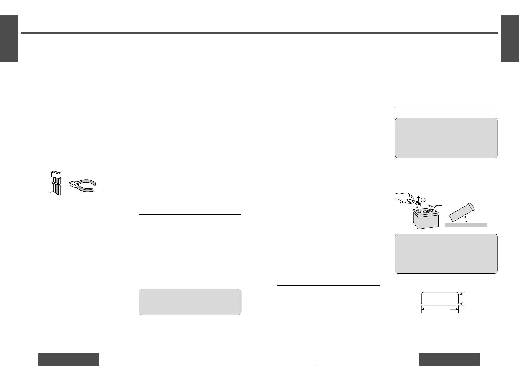
≥Disconnect the cable from the negative -battery
terminal (see caution below).
≥Unit should be installed in a horizontal position
with the front end up at a convenient angle, but
not more than 30o.
Caution:
≥Do not disconnect the battery terminals of a
car with a trip or navigational computer since
all user settings stored in memory will be lost.
Instead take extra care with installing the unit
to prevent shorts.
Less than 30x
Dashboard Installation
Installation Opening
182 mm
53 mm
This unit can be installed in any dashboard having
an opening as shown above. The dashboard should
be 4.75 mmj5.56 mm thick in order to be able to
support the unit.
The first step in installation is to identify all the car
wires you’ll use when hooking up your sound system.
As you identify each wire, we suggest that you label
it using masking tape and a permanent marker.
This will help avoid confusion when making connections later.
Note:
≥Do not connect the power connector to the stereo
unit until you have made all connections. If there
are no plastic caps on the stereo hooking wires,
insulate all exposed leads with electrical tape until
you are ready to use them. Identify the leads in
the following order.
Power Lead
If your car has a radio or is pre-wired for one:
Cut the connector wires one at a time from the plug
(leaving the leads as long as possible) so that you
can work with individual leads.
❐ Identify All Leads
Turn the ignition on to the accessory position, and
ground one lead of the test bulb to the chassis.
Touch the other lead of the test bulb to each of the
exposed wires from the cut radio connector plug.
Touch one wire at a time until you find the outlet
that causes the test bulb to light.
Now turn the ignition off and then on. If the bulb
also turns off and on, that outlet is the car power
lead.
If your car is not wired for an audio unit:
Go to the fuse block and find the fuse port for radio
(RADIO), accessory (ACC), or ignition (IGN).
Battery Lead
If your stereo unit has a yellow lead, you will need
to locate the car’s battery lead. Otherwise you may
ignore this procedure. (The yellow battery lead provides continuous power to maintain a clock, memory storage, or other function.)
If your car has a radio or is pre-wired for one:
With the ignition and headlights off, identify the car
battery lead by grounding one lead of the test bulb
to the chassis and checking the remaining exposed
wires from the cut radio connector plug.
If your car is not wired for an audio unit:
Go to the fuse block and find the fuse port for the
battery, usually marked BAT.
Speakers
Identify the car speaker leads. There are two leads
for each speaker which are usually color coded.
A handy way to identify the speaker leads and the
speaker they are connected with is to test the leads
using a 1.5 V AA battery as follows.
Hold one lead against one pole of the battery and
stroke the other lead across the other pole. You will
hear a scraping sound in one of the speakers if you
are holding a speaker lead.
If not, keep testing different lead combinations until
you have located all the speaker leads. When you
label them, include the speaker location for each.
Antenna Motor
If your car is equipped with an automatic power antenna, identify the car motor antenna lead by connecting one bulb tester lead to the car battery lead
and touching the remaining exposed wires from the
cut radio connector plug one at a time. You will
hear the antenna motor activate when you touch
the correct wire.
Antenna
The antenna lead is a thick, black wire with a metal
plug at the end.
❐ Connect All Leads
Now that you have identified all the wires in the car,
you are ready to begin connecting them to the
stereo unit wires. The wiring diagram (➡ pages 25,
26) shows the proper connections and color coding
of the leads.
We strongly recommend that you test the unit before making a final installation.
You can set the unit on the floor and make temporary connections to test the unit. Use electrical tape
to cover all exposed wires.
Important:
≥Connect the red power lead last, after you
have made and insulated all other connections.
Ground
Connect the black ground lead of the power connector to the metal car chassis.
Page 9
E
N
G
L
I
S
H
CQ-DF501/DF301W
23
E
N
G
L
I
S
H
13
CQ-DF501/DF301W
22
Installation Guide (Continued)
E
N
G
L
I
S
H
14
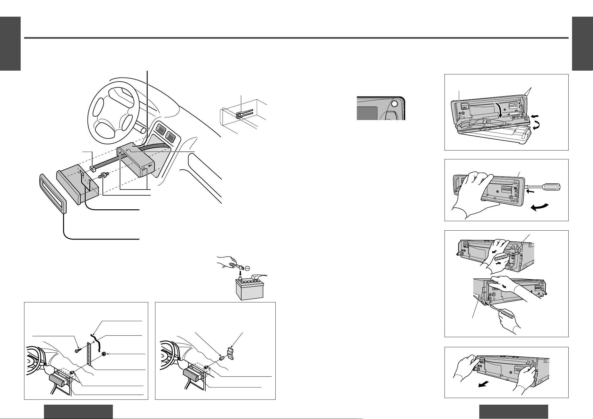
Remove the removable face plate.
1 Press [OPEN]. The removable face plate will
be opened.
2 Push the face plate to the left.
3 Pull it out toward you.
1
2
Remove the Unit
Lock lever
Lock lever
Screwdriver
8 Trim plate
REP
45WX4
RANDOM
OPEN
Remove the trim plate 8 with a screwdriver.
Pull out the unit while pushing down the lock
lever with a screwdriver.
Remove the unit pulling with both hands.
1
2
3
4
1 Open
2 Push
3 Pull out
Contact
Main unit
Switch off the power of the unit.
First complete the electrical connections, and
then check them for correctness. (➡ pages
25, 26)
6 Power connector
Lock lever (§)
Mounting tabs
5 Mounting bolt
❐ Installation Procedures
Insert mounting collar 1 into the dashboard, and
bend the mounting tabs out with a screwdriver.
Make sure that the lock lever (§) is flush with the
mounting collar 1 (not projecting outward).
(a) Using the rear support strap 3
4 Tapping screw
(5 mm·a16 mm)
2 Hex. nut
(5 mm·)
3 Rear support
strap
5 Mounting bolt
(5 mm·)
1 Mounting collar
Fire wall of car
3 mm·
(b) Using the rubber cushion (option)
5 Mounting bolt
(5 mm·)
1 Mounting collar
Rear support bracket
(provided on the car)
Rubber cushion (option)
Lock lever (§)
1
Secure the rear of the unit.
After fixing mounting bolt 5and power connector
6
, fix the rear of the unit to the car body by either
method (a) or (b) shown below.
Insert trim plate 8.
After installation, reconnect the negative - battery terminal.
2
3
4
Page 10
E
N
G
L
I
S
H
CQ-DF501/DF301W
25
Electrical Connections
E
N
G
L
I
S
H
15
CQ-DF501/DF301W
24
Anti-Theft System
E
N
G
L
I
S
H
16
No. Item Q’ty
6 Power connector 1
Recommended external amplifier combination (example)
≥Pre-amp out (rear/front) [CY-M9054 (4 channels system)]
≥Subwoofer out [CY-M9054 (2 channels system) or CY-M7052 (1 channel system)]
Cautions:
≥This product is designed to operate of a 12 V DC, negative ground battery system.
≥To prevent damage to the unit, be sure to follow the wiring diagram on the next page.
≥Remove approx. 5 mm of protective covering from the ends of the leads before connecting.
≥Do not insert the power connector into the unit until the wiring is completed.
≥Be sure to insulate any exposed wires from a possible short-circuit from the car chassis. Bundle all cables
and keep cable terminals free from touching any metal parts.
≥Remember, if your car has a drive computer or a navigation computer, the data of its memory may be
erased when the battery terminals are disconnected.
Accessory used for wiring
Display Security indicator
Blinks
OFF
Security Indicator
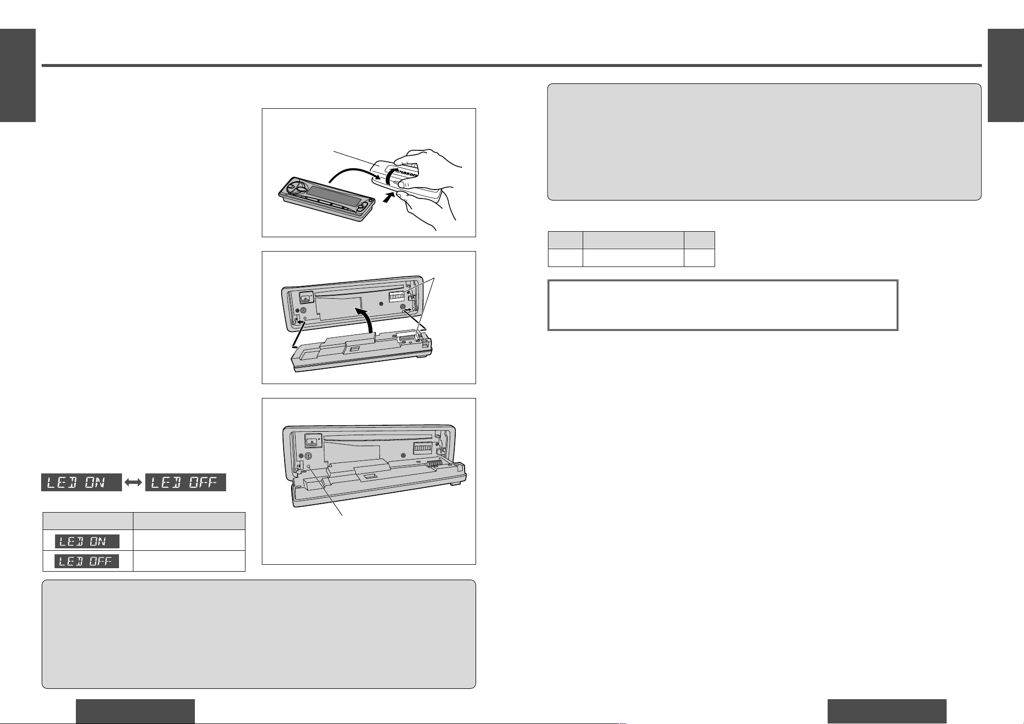
The security indicator blinks when the removable
face plate is removed from the unit.
Press and hold [SEL] to turn the security indicator
on or off. (“LED ON” or “LED OFF”).
Install Removable Face Plate
1 Fit the face plate with its left hole on one of the
pins provided on the main unit.
2 Fit the other hold on the other pin applying
slight pressure.
3 Move the face plate up and down a few times to
make sure it is secure. Then close the front
panel and press down the right side of the face
plate until it clicks into plate.
Cautions:
≥This face plate is not water-proof. Do not expose it to water or excessive moisture.
≥Do not remove the face plate while driving your car.
≥Do not place the face plate on the dashboard or nearby areas where the temperature rises to high level.
≥Do not touch the contacts on the face plate or on the main unit, since this may result in poor electrical
contacts.
≥If dirt or other foreign substances get on the contacts, wipe them off with a clean and dry cloth.
≥Do not apply a strong downward force onto the face plate and do not put anything on it while it is open, or
it might be damaged.
This unit is equipped with a removable face plate. Removing this face plate makes the radio totally inoperable.
The security indicator will blink.
Place the Removable Face
Plate into Case
1 Switch off the power of the unit.
2 Remove the removable face plate. (➡ page 23)
3 Gently press the button of the case and open
the cover. Place the face plate into the case and
take it with you when you leave the car.
2
1
3
7 Removable face plate case
Security indicator
Contact
Default
(Continued to the next page.)
Page 11
E
N
G
L
I
S
H
CQ-DF501/DF301W
27
Troubleshooting
E
N
G
L
I
S
H
17
CQ-DF501/DF301W
26
Electrical Connections (Continued)
E
N
G
L
I
S
H
18
Preliminary Steps
Check and take steps as described in the tables below.
If You Suspect Something Wrong
Immediately switch power off.
Disconnect the power connector and check that there is neither smoke nor heat from the unit before asking for repairs.
Never try to repair the unit yourself because it is dangerous to
do so.
No power.
Trouble
Car’s engine switch is not on.
➡Turn your car’s ignition switch to ACC or ON.
Troubleshooting Tips
❐ Common
Cables are not correctly connected.
➡Connect cables correctly.
Battery cable is not correctly connected.
➡Connect the battery cable to the terminal that is always live.
Accessory cable is not correctly connected.
➡Connect the accessory cable to your car’s ACC source.
Grounding wire is not correctly connected.
➡Connect the grounding wire to a metal part of the car.
Fuse is burnt.
➡Call the store where you purchased the unit, or your nearest service
station and ask for fuse replacement.
No sound.
Mute is set to ON.
➡Set it to OFF.
Cables are not correctly connected.
➡Connect cables correctly.
Condensation (dew)
➡Wait for a while before use.
Cautions:
≥Do not use the unit if it malfunctions or
is something wrong.
≥Do not use the unit in abnormal condi-
tion, for example, without sound, or
with smoke or foul smell, can cause ignition or electric shock. Immediately
stop using it and call the store where
you purchased it.
Cause/Step
❐ Radio
Much noise in FM stereo
and monaural broad-
casts.
Station is too far, or signals are too weak.
➡Select other stations of higher signal level.
Battery cable is not correctly connected.
➡Connect the battery cable to the terminal that is always live.
Preset station is reset.
Trouble Cause/Step
White
Red
(MONO)
Power connector
Antenna
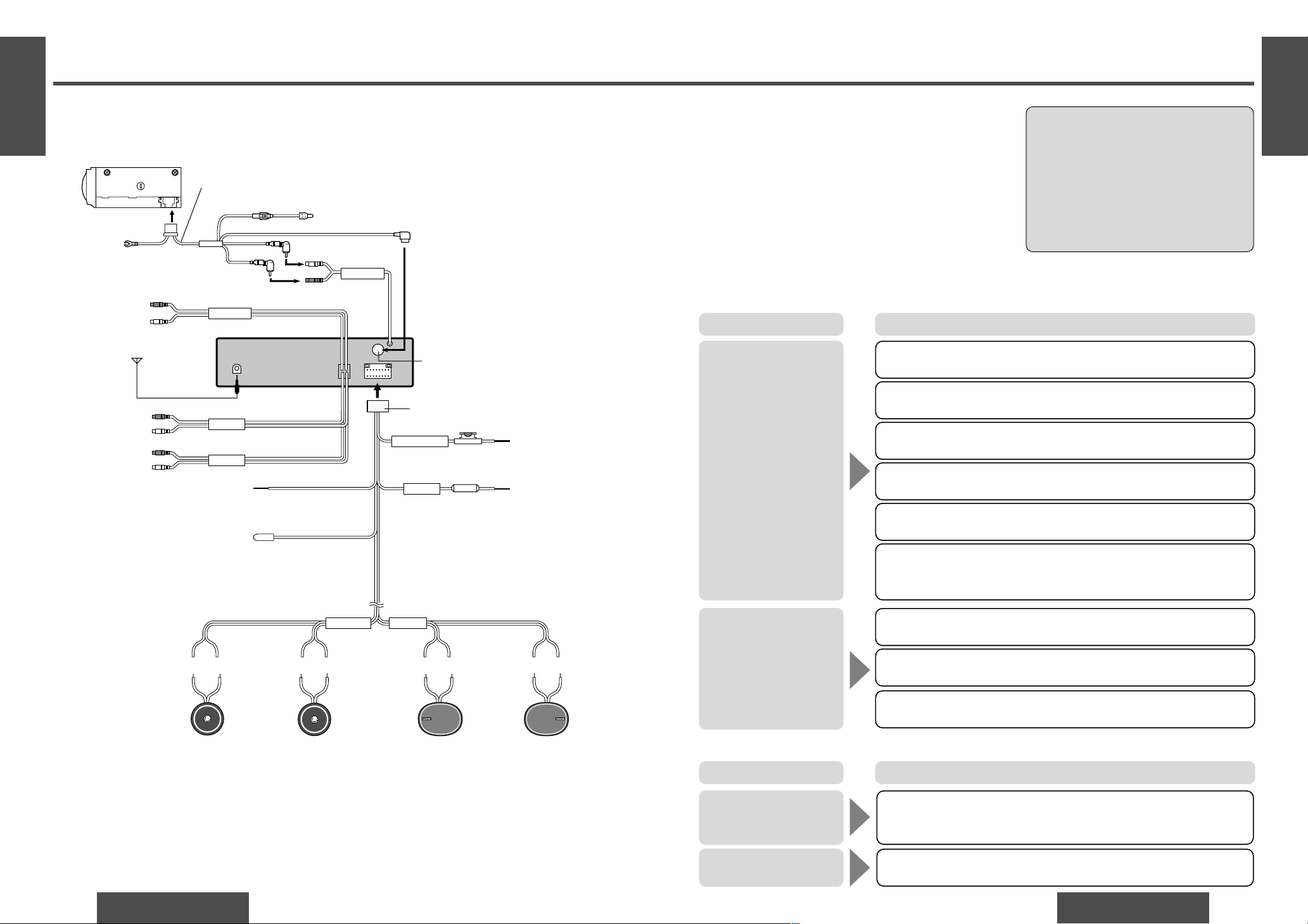
6
CD changer control connector
CD changer
CX-DP88
Battery lead
Yellow
DIN cord
Fuse (3 A)
Yellow
BATTERY 15A
Battery lead
To the car battery,
continuous +12 V DC
Fuse (15 A)
Red
Resistor (1 k≠)
ACC
Power lead
To ACC power,
+12 V DC
Dark blue
Black
Ground lead
To a clean, bare metallic
part of car chassis.
CD•C-IN
White (L)
Red (R)
White (L)
Red (R)
White (L)
Red (R)
(r)(s)(r)(s)(r)(s)(r)(s)
Left speaker
(Front)
Right speaker
(Front)
White Gray Green VioletWhite/black
stripe
Green/black
stripe
Violet/black
stripe
Gray/black
stripe
FRONT SP REAR SP
Left speaker
(Rear)
Right speaker
(Rear)
S•W-OUT
REAR
FRONT
Preout cord (rear)
Preout cord (front)
Speaker lead
Ground lead
Be sure to connect to a well
grounded metallic part of your car
because noises or troubles may occur.
DIN extension cord (DIN/BATT/RCA/GND)
Black
Subwoofer cord
RCA cord
CQ-DF501W/CQ-DF301W
Motor antenna relay control lead
(To motor antenna) (Max. 500 mA)
This lead is not intended for use with
switch actuated power antenna.
Amp. relay control power lead
This lead is for connection to the power amplifier.
❐ Wiring Diagram
Page 12
E
N
G
L
I
S
H
CQ-DF501/DF301W
29
E
N
G
L
I
S
H
19
CQ-DF501/DF301W
28
Troubleshooting (Continued)
E
N
G
L
I
S
H
20
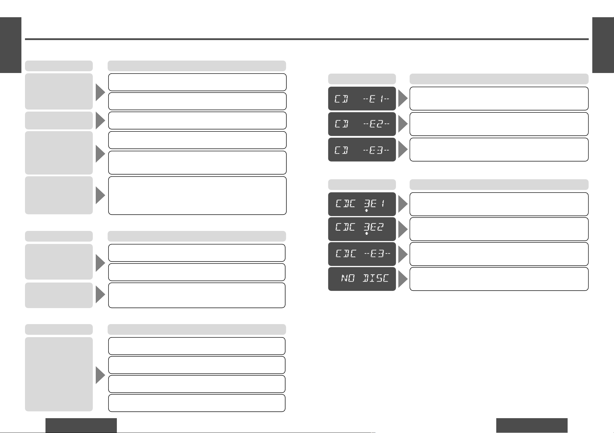
Error Display Messages
❐ CD
Disc has scars.
➡Press [OPEN] to open the front panel, and then press [<] (EJECT) to
eject the disc.
Disc is dirty, or is upside down.
➡Press [OPEN] to open the front panel, and then press [<] (EJECT) to
eject the disc.
No operation by some cause.
➡Turn off the car engine (ACC off) and remove the fuse from the battery
lead (yellow) for 1 minute. Then reinstall the fuse.
Display Cause/Step
Maintenance
Your product is designed and manufactured to ensure a minimum of maintenance. Use a soft cloth for routine
exterior cleaning. Never use benzine, thinner or other solvents.
Product Servicing
If the suggestions in the charts do not solve the problem, we recommend that you take it to your nearest authorized Panasonic Servicenter. The product should be serviced only by a qualified technician.
Replacing the Fuse
Use fuses of the same specified rating (15 A). Using different substitutes or fuses with higher ratings, or connecting the unit directly without a fuse, could cause fire or damage to the stereo unit.
If the replacement fuse fails, contact your nearest Panasonic Servicenter for service.
❐ CD Changer
Disc has scars.
➡Select the next available compact disc.
Disc is dirty, or is upside down.
➡Select the next available compact disc.
No disc in the changer (magazine).
➡Insert discs into the changer (magazine).
No operation by some cause.
➡Press [RESET] on the CD changer (optional).
Notes:
≥There may be cases where the disc numbers affected by an error are displayed before “E1” or “E2”.
≥Displays and the steps to be taken for errors vary in part from changer to changer. For details, refer to the
operating instructions for the changer used.
DISC No.
DISC No.
Display Cause/Step
CD is dirty.
➡Clean CD, referring to the section on “Notes on CD”.
Mounting angle is over 30o.
➡Adjust mounting angle to less than 30o.
Instable mounting.
➡Mount the unit securely with the mounting parts, referring to the
section on installation.
≥ CD is defective.
≥ Mechanical trouble.
➡Press [OPEN] to open the panel and press [<] (EJECT). If normal
operation is not restored yet, call the store where you purchased the
unit or the nearest service station to ask for repairs.
CD sound skips, tone
quality is low.
Sound skips due to vibration.
CD is not ejected.
CD is inside but no
sound.
CD is upside down.
➡Place CD in the correct direction, and the label side up.
❐ CD
CD is dirty.
➡Clean CD, referring to the section on “Notes on CD”.
Trouble Cause/Step
No sound from left,
right, front or rear
speakers.
Left and right balance, or front and rear balance is off on one side.
➡Adjust balance/fader mode as appropriate.
❐ Sound Setting
The right speaker wire is connected to the left speaker and the left speaker wire to the right speaker.
➡Connect the speaker wires to the correct ones.
Left and right sounds are
reversed in stereo listening.
Buttons are invalid for
operation.
Battery poles (i) (j) are reversed.
➡Insert the battery correctly.
❐ Remote Control
Wrong the battery.
➡Check the battery.
Battery has run down.
➡Replace the battery.
Remote control is in the wrong direction.
➡Direct the remote control at sensor (REMOTE) on the panel.
Trouble Cause/Step
Trouble Cause/Step
Cables are not correctly connected.
➡Connect the cables correctly.
Page 13
E
N
G
L
I
S
H
CQ-DF501/DF301W
31
Specifications
E
N
G
L
I
S
H
21
CQ-DF501/DF301W
30
Maintenance
E
N
G
L
I
S
H
22
❐ General
Power supply: 12 V DC (11 Vj16 V), test voltage 14.4 V, negative ground
Current consumption: Less than 2.2 A (CD play mode; 0.5 Wa4 channels)
Maximum power output: 45 Wa4 channels at 400 Hz, Volume control maximum
Power output: 22 Wa4 channels at 400 Hz (DIN 45 324, at 4 ≠)
Tone adjustment range:
Bass: n12 dB at 100 Hz
Treble: n12 dB at 10 kHz
Suitable speaker impedance: 4j8 ≠
Pre-Amp output voltage: 4.0 V (CD play mode; 1 kHz, 0 dB) (CQ-DF501W)
2.0 V (CD play mode; 1 kHz, 0 dB) (CQ-DF301W)
Subwoofer output voltage: 4.0 V (CQ-DF501W)
2.0 V (CQ-DF301W)
Output impedance: 200 ≠
Dimensions (WaHaD): 178a50a150 mm
Weight: 1.5 kg
❐ FM Stereo Radio
Frequency range: 87.5 MHzj108.0 MHz
Usable sensitivity: 11.0 dBf. (1.25
¨V,
75 ≠)
50 dB quieting sensitivity: 15.2 dBf. (1.6
¨V,
75 ≠)
Frequency response: 30 Hzj15 kHz (n3 dB)
Alternate channel selectivity: 75 dB
Stereo separation: 42 dB (1 kHz)
Image response ratio: 75 dB
IF response ratio: 100 dB
Signal/noise ratio: 70 dB
❐ AM Radio
Frequency range: 531 kHzj1 602 kHz
Usable sensitivity: 28 dB/¨V (25
¨V,
S/N 20 dB)
❐ CD Player
Sampling frequency: 32 times oversampling
DA converter: MASH • 1 bit/4 DAC system
Error correction system: Panasonic super decoding algorithm
Pick-up type: Astigma 3-beam
Light source: Semiconductor laser
Wave length: 780 nm
Frequency response: 20 Hzj20 kHz (n1 dB)
Signal/noise ratio: 96 dB
Total harmonic distortion: 0.01 % (1 kHz)
Wow and flutter: Below measurable limits
Channel separation: 75 dB
Note:
≥ Specifications and the design are subject to modification without notice due to improvements in technology.
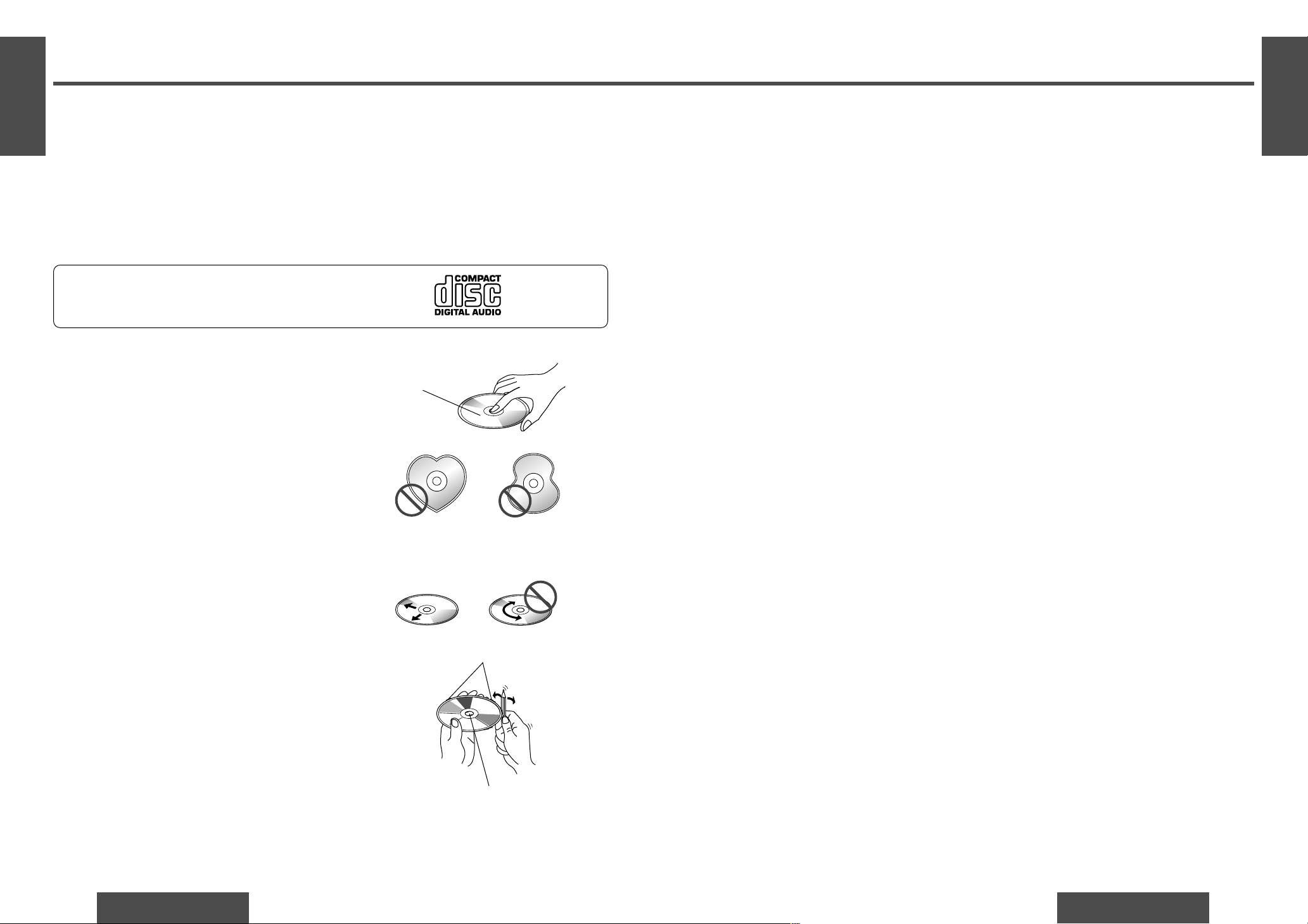
How to hold the CD
≥ Do not touch the underside of the disc.
≥ Do not make scratches on the discs.
≥ Do not bend disc.
≥ When not in use, keep CD in the case.
Do not use irregular shaped CDs.
Do not leave discs on the following places:
≥ Direct sunlight
≥ Near car heaters
≥ Dirty, dusty and damp areas
≥ Seats and dashboards
Disc cleaning
Use a dry, soft cloth to wipe from the center outward.
Caution on new discs
A new disc may have rough edges on its inner and outer
perimeter. These may cause malfunction.
Remove the rough edges using a pencil, etc.
ONLY USE DISCS CARRYING THE LABEL
Care of the Unit
❐ Cleaning this Unit
Use a dry, soft cloth to wipe.
❐ Caution on Cleaning
Never use solvents such as benzine, thinner as they
may mar the surface of the unit.
Notes on CD
Label side
<Right> <Wrong>
Rough edge
Rough edge
Do not use irregular shaped CDs.
 Loading...