

Page 1

CM602-L
Reference Manual
Page 1-1
1.
1. GENERAL DESCRIPTION
This chapter describes the following items.
Names and mechanisms of units
This describes the names and functions of each unit using the illustrations.
Production process
This describes the placement process step by step.
Specifications
This describes the specifications of the machine and applicable boards.
∗
This machine can use the high-speed head (12 nozzles / 8 nozzles) and the multi-functional
head.
EJM4A-E-RMA01-A00-01
Page 2
CM602-L
Reference Manual
1.1 Names and Mechanisms of Units
Page 1-2
1.
1.1 Names and Mechanisms of Units
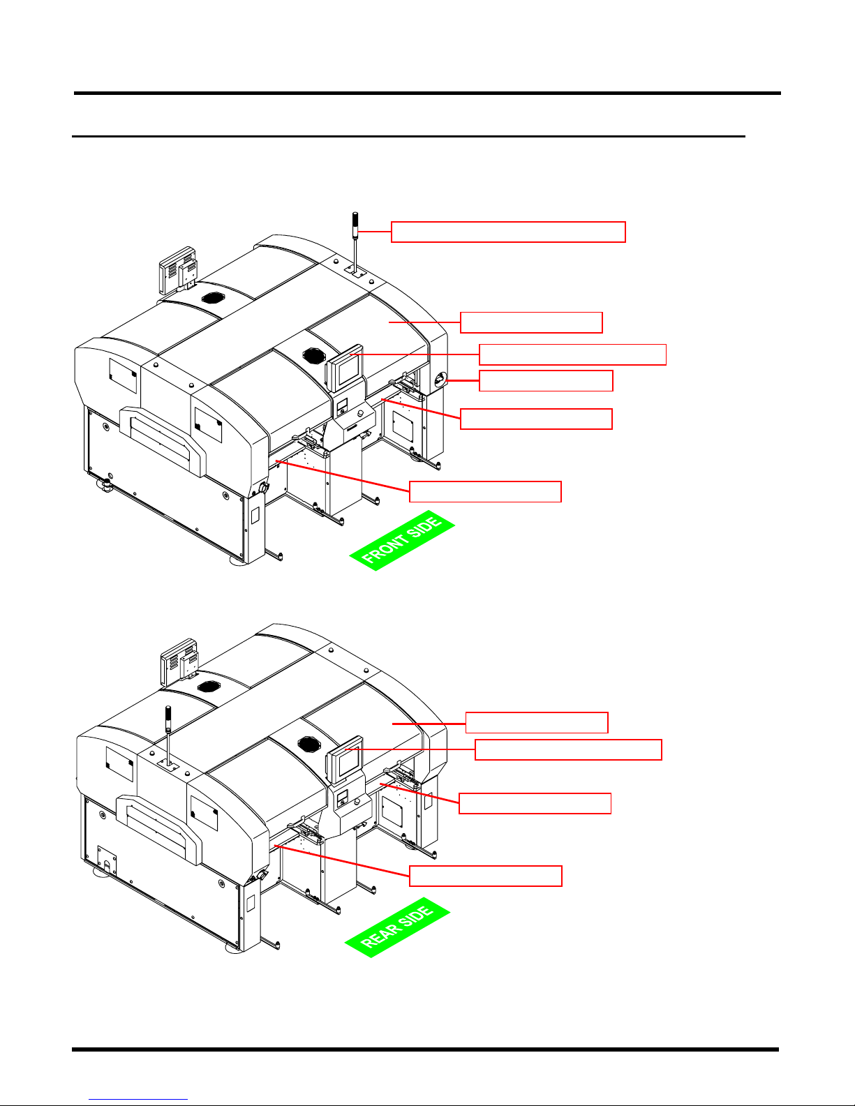
1.1.1 External Views
1. Front view
2. Rear view
EJM4A-E-RMA01-A01-00
EJM4A-AB01
Rear cover
Feeder table 2
Feeder table 4
Rear color touch panel
EJM4A-AA01
Status indicator (Three-color signal tower)
Front cover
Power supply switch
Feeder table 3
Feeder table 1
Front color touch panel
Page 3
CM602-L
Reference Manual
1.1 Names and Mechanisms of Units
Page 1-3
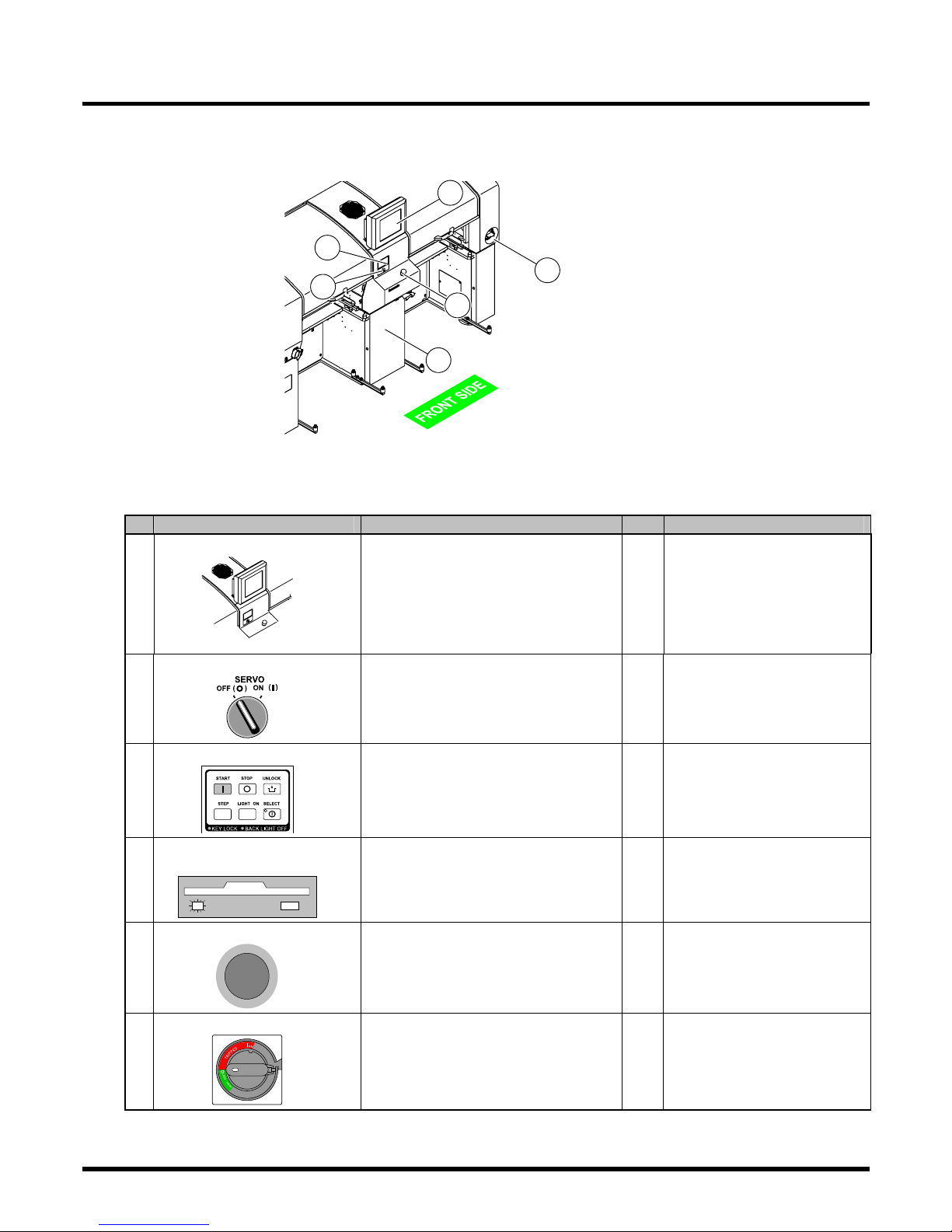
1.1.2 Operating Units
1. Front view
∗
The emergency stop button, color touch panel, operating panel, and servo switch of the same
number exist on the rear side.
No.
Unit name
Function Qty. Reference item
Color touch panel
EJM4A-412E
Used to operate the machine. 2 Operation Manual
Servo switch
Used to turn ON/OFF the servo-system
power.
2 Operation Manual
Operating panel
Used to put the machine into operation,
bring it to a stop, and for the other
operations.
2 Operation Manual
Floppy disk drive
(Inside the cover)
Used to read and write programming
data.
1 • Programming Manual
• Handling of floppy disk
Emergency stop button
If this button is pressed, the machine
comes to an emergency stop.
2 Safety precautions
Power supply switch
Used to turn ON/OFF the power and air
sources of the machine. (When the
power supply switch is turned OFF, air
becomes OFF in synchronization with
that.)
1 Safety precautions
EJM4A-E-RMA01-A01-00
EJM4A-AA01
1
2
3
4
5
6
Page 4
CM602-L
Reference Manual
1.1 Names and Mechanisms of Units
Page 1-4
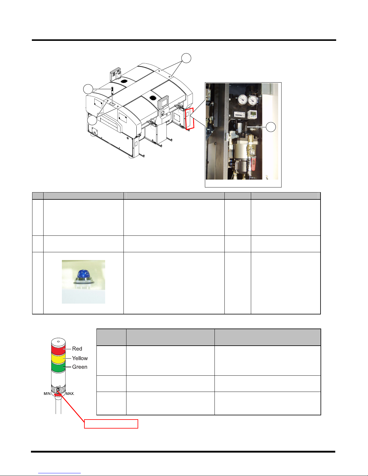
2. Rear view
No. Unit name Function Qty. Reference item
Status indicator
(Three-color signal tower)
Indicates the machine’s operational
status, and warns you of any trouble
occurred during operation by sounding
a buzzer. You can adjust the volume of
buzzer using the knob.
1 See below.
Regulator knob
(Inside the cover)
Used to adjust the supply air pressure. 1 Operation Manual
Stage indicator lamp
EJM4A-019P
If components run out or trouble occurs,
the corresponding stage lamp blinks.
During automatic operation
• Not lit: Normally running
• Lit: Components have run out.
• Blinking: Warning of the shortage of
component
During teaching
• Lit: Running
4
Explanation of status indicator lamp (three-color signal tower)
Color,
Status
Description Trouble description
Red,
Blinking
Trouble; operation cannot be
continued. (Emergency stop)
• Emergency stop
• Trouble in shafts of motors, etc.
• Drop in air pressure
• Board transport trouble
Yellow,
Blinking
Trouble or warning; operation can
be continued.
Immediate/Cycle stop, Out of materials
Green, Lit
During automatic operation, or
during machine adjustment
running
Normally running
EJM4A-E-RMA01-A01-00
EJM4A-122E
Knob
4Z4C-AB01
EJM4A-062P
3
1
3
2
Page 5

CM602-L
Reference Manual
1.1 Names and Mechanisms of Units
Page 1-5
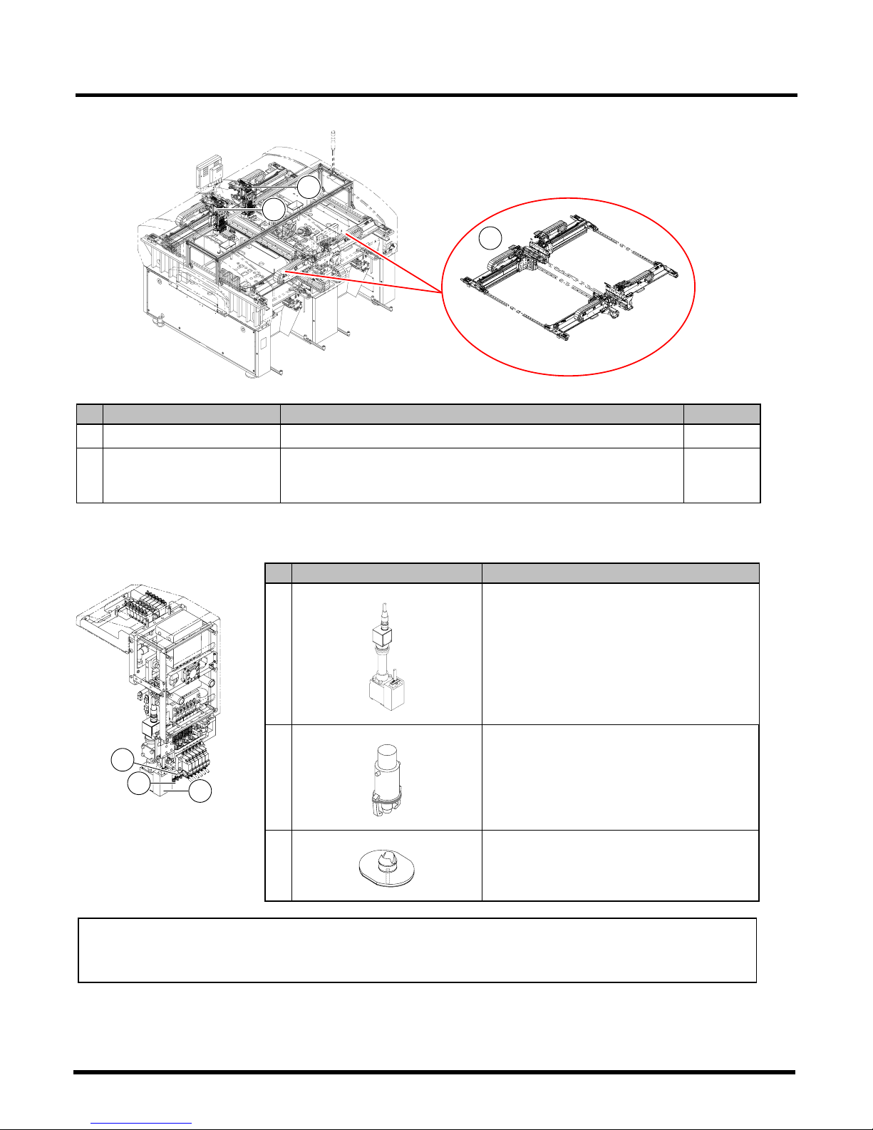
1.1.3 Main Units
No.
Unit name Function Qty.
Board conveyor L/R
4Z4C-030TC0AA
4Z4C-030UC0AA
This unit loads and unloads boards.
In placement, it secures a board by
sandwiching it in between the Y and
the Z direction, and keeps it at the
placement position.
1 on the
L/R side
each
Line camera
4Z4C-161DC1AA
This camera is used to recognize
components.
It supports the recognition of all the
components, from minute ones to
large-sized irregular-shaped ones.
4
Nozzle changer
Standard for multi-functional head
4ZTC-050NC1AA
Option
High-speed head (12 nozzles) High-speed head (8 nozzles)
EJM4A-153E00. 4ZTC-050MC1AA
In changing boards, this unit
changes nozzles automatically.
4
EJM4A-E-RMA01-A01-01
EJM4A-112E
2
2
3
3
1
1
Page 6
CM602-L
Reference Manual
1.1 Names and Mechanisms of Units
Page 1-6
No.
Unit name
Function
Qty.
XY unit
These units move the head unit in place fast and precisely.
4
Transfer head
This unit transfers chips from feeders to a board.
The high-speed head is equipped with 12 or 8 nozzle holders, and
the multi-functional head is equipped with 3 nozzle holders.
4
Detailed explanation of transfer head
∗
Description uses the illustrations for the high-speed head (12 nozzles).
No.
Unit name Function
Head camera
EJM4A-142E
This camera is used for the board recognition,
heat compensation, and calibration.
Nozzle holder
444C-402E
Nozzles are fit in this holder. The high-speed
head is equipped with 12 or 8 nozzle holders,
and the multi-functional head is equipped with
3 nozzle holders.
Nozzle
444C-407E
This picks up components with a vacuum
pressure.
There are various kinds of sizes and shapes
of nozzles in response to components.
NOTICE
The conventional transfer head of CM402 cannot be installed.
(However, the lightweight head can be installed.)
EJM4A-143E
5
5
EJM4A-144E
4
EJM4A-E-RMA01-A01-01
EJM4A-152E
7
8
6
Page 7
CM602-L
Reference Manual
1.1 Names and Mechanisms of Units
Page 1-7
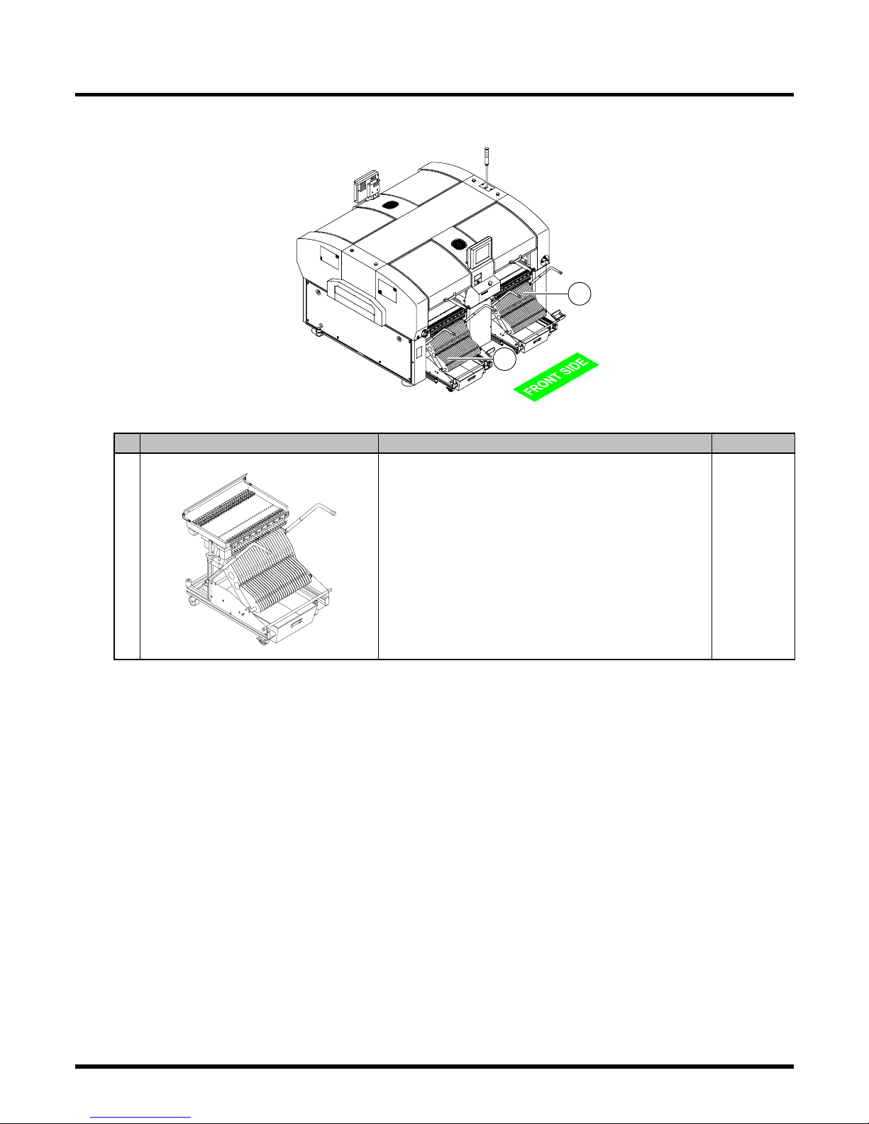
1.1.4 Component Feeding Unit
No. Unit name Function Qty.
Collectively changing truck
4Z4C-15XYC1AA
This is a truck where intelligent feeders are placed.
∗
When the collectively changing truck preparation unit
(option) is available, the preparation work is available
while this machine is running.
4
EJM4A-E-RMA01-A01-00
EJM4A-AC01
1
1
Page 8
CM602-L
Reference Manual
1.1 Names and Mechanisms of Units
Page 1-8
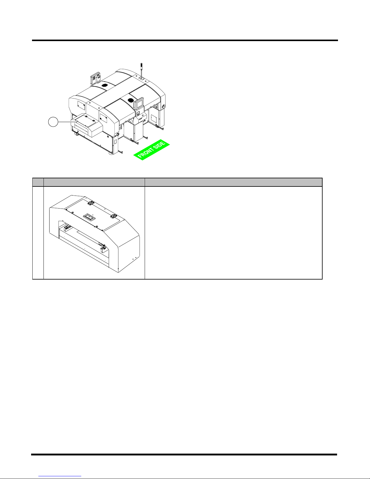
1.1.5 Extension Conveyor (Option)
No. Unit name Function
Extension conveyor
E64C-010E
This unit extends the conveyor.
It can be installed on both the upstream and the downstream process
side.
Since its cover is equipped with a safety switch, the machine cannot
be operated with that cover open. If the cover is opened during
operation, the safety cover error occurs.
For the standard specifications (with no extension conveyor), the
safety sensor is included because an opening for transport is close to
movable parts. When, however, the extension conveyor is included,
the safety sensor is not included because a safe distance between an
opening for transport and movable parts is secured.
∗
For the extension conveyor, there is no safety sensor of transport
section.
EJM4A-E-RMA01-A01-00
EJM4A-AG01
1
Page 9
CM602-L
Reference Manual
1.1 Names and Mechanisms of Units
Page 1-9
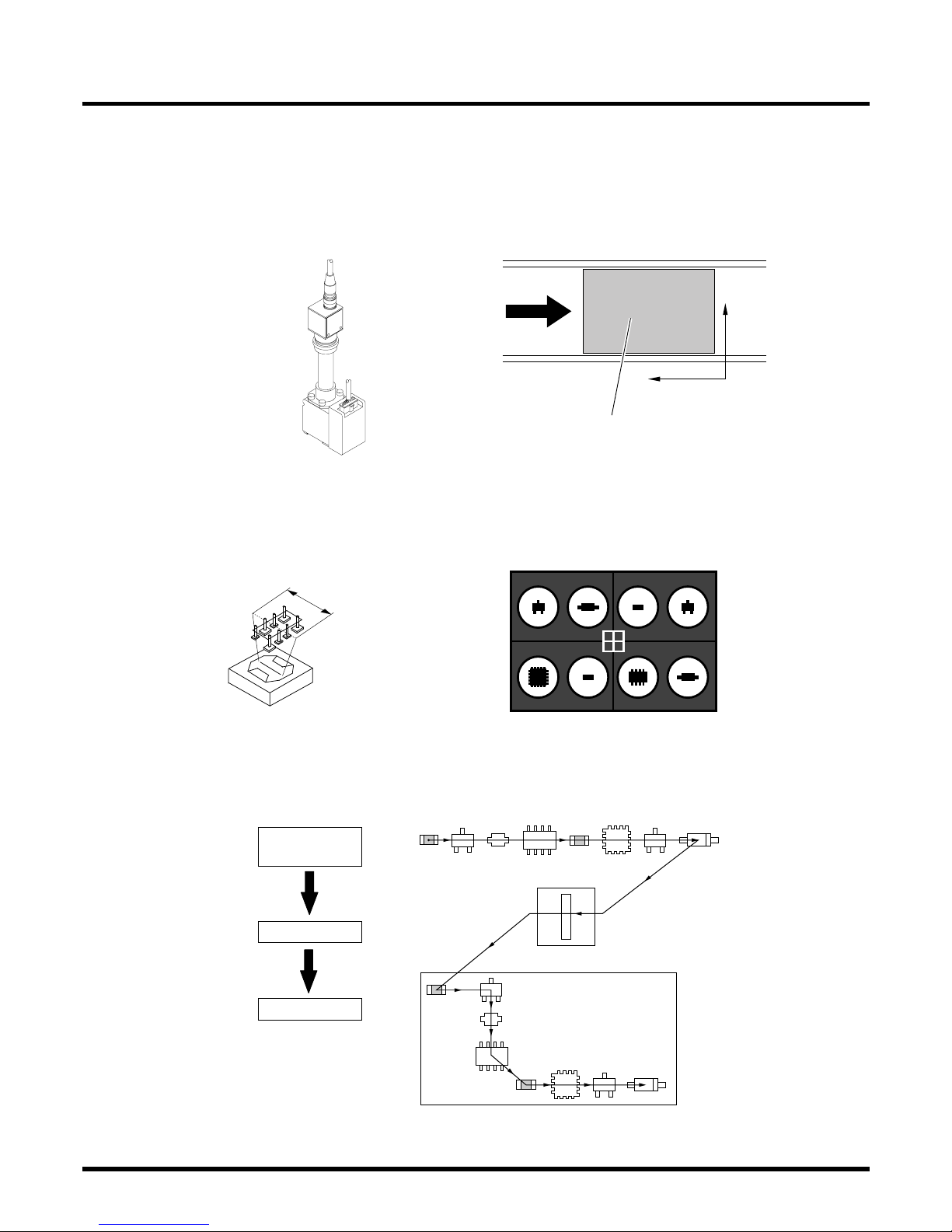
1.1.6 Recognition Camera
This machine has the two recognition cameras: head camera and line camera.
A) Head camera
The head camera is installed on the head unit, and recognizes the precise position of board.
∗
Description uses the illustrations for the high-speed head (8 nozzles).
EJM4A-142E
Y
X
4Z4C-009E
Positioning reference
Board
B) Line camera
The line camera is installed on the main-body frame, and recognizes components (displacement,
inclination, chipping, etc.).
Line camera
Line width: 55 mm
4Z4C-001E
Conceptual illustration
Recognition image
4Z4C-002E
Conceptual illustration
Process
Eight components are scanned and recognized all together, while the head is moved so that it
will cross over the line.
Component
pickup
Recognition
Placement
EJM4A-E-RMA01-A01-01
Start
Batch recognition
Board
4Z4C-006E
Page 10
CM602-L
Reference Manual
1.2 Placement Mechanism
Page 1-10
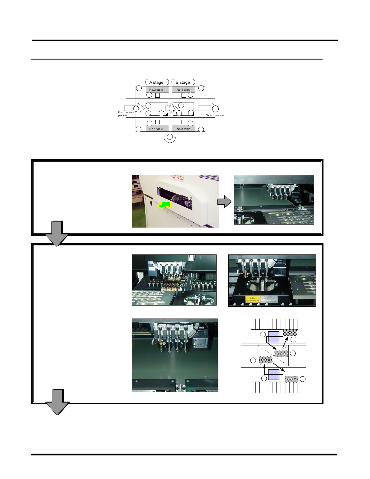
1.2 Placement Mechanism
Machine’s movable parts
Rear side
Front side
∗
Description uses the photos for the high-speed head (8 nozzles).
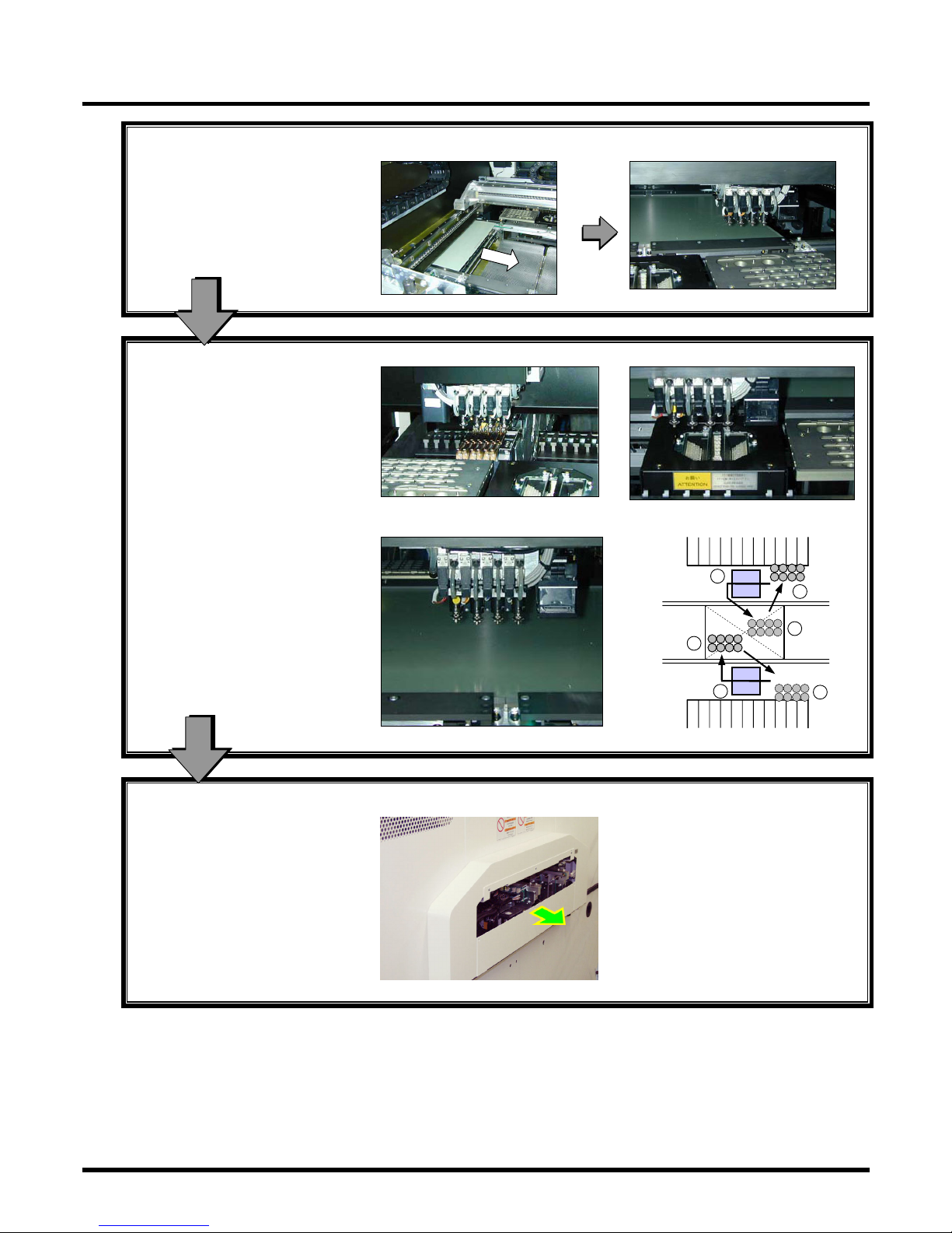
1. Loading board
A board is loaded from the
upstream process.
The board is clamped and
recognized.
A board unloaded from the
upstream process is set in the board
holder on the A stage.
EJM4A-024P
4Z4C-029P
2. Placing components
Components are picked up.
Components are recognized.
Two transfer heads place
components at high speed.
4Z4C-032P
4Z4C-030P
Alternate placement
Components are placed.
A-stage
While one head recognizes →
places components, another picks
up → recognizes components.
4Z4C-031P
4Z4C-003E
To “3. Transporting board”
EJM4A-E-RMA01-A01-01
3
2
4
4
3
2
4Z4C-010E
0
10
2 7
3 8
4
4 1
9
6
9
3
8
5
2 7
Page 11
CM602-L
Reference Manual
1.2 Placement Mechanism
Page 1-11
3. Transporting board
The board is loaded from the A
stage.
The board is clamped and
recognized.
The board on which the
components have been placed at
the A stage is transported to the B
stage.
4Z4C-033P
4Z4C-029P
4. Placing components
Components are picked up.
Components are recognized.
As with the A stage, the two transfer
heads place components at high
speed.
4Z4C-032P
4Z4C-030P
Components are placed.
B-stage
4Z4C-031P
4Z4C-003E
5. Unloading board
The board is unloaded to the
downstream process.
The board on which the
components have been placed is
unloaded to the downstream
process.
EJM4A-025P
EJM4A-E-RMA01-A01-01
8
7
9
9
8
7
Page 12

CM602-L
Reference Manual
1.3 Equipment Specifications
Page 1-12
1.3 Equipment Specifications
1.3.1 Machine Specifications
Item
Specifications
Control system
Microcomputer system
External memory
The data is managed by PT
∗
4
.
Approximately 1 MB is required for a piece of data. (One type per 3.5-inch 2HD floppy disk)
Program data
∗
1
Point count: Max. 10000 points
Machine body
Normal service source: Three-phase 200/220 VAC ±10 VAC,
Three-phase 380/400/420/480 VAC ±20 VAC
Frequency: 50/60 Hz
Power source
Power supply for
HUB
∗
3
Single-phase 100 VAC to 240 VAC, Frequency: 50/60 Hz
Machine body
4.0 kVA
Rated capacity
Power supply for
HUB
∗
3
140 VA
Supply air pressure 0.49 MPa to 0.78 MPa (Working air pressure: 0.49 MPa to 0.54 MPa)
Supply air volume 170 L/min (A.N.R.)
Outside dimension
2350 mm (W) × 2690 mm (D) × 1430 mm (H)
(Three-color signal tower and color touch panels not included)
Mass of main body
3400 kg (Standard configuration, excluding 140 kg of a collectively
changing truck)
Mass
∗
2
Mass of collectively
changing truck
140 kg (per unit)
Mass of standard
configuration
3960
kg
(One main body and four collectively changing trucks)
Environmental
condition
Temperature: 10°C to 35°C
Humidity: 25% RH to 75% RH (No condensation)
Transportation and
storage condition
Temperature: −20°C to 60°C
Humidity: 75% RH or less (No condensation)
Altitude
1000 m or less, above sea level
Noise
< 70 dB (A)
∗
1
: The data is created by PT. This machine can modify only some data.
∗
2
: Mass of the main body excluding the optional units
∗
3
: The power supply for HUB is an option. This power supply is required when you wish to
communicate with PT while the main power supply is OFF.
∗
4
: PT (Programming Terminal Support System), which creates and manages the production data.
EJM4A-E-RMA01-A01-00
Page 13

CM602-L
Reference Manual
1.3 Equipment Specifications
Page 1-13
1.3.2 Basic Performance
Description
Item
High-speed head (12 nozzles) High-speed head (8 nozzles)
Multi-functional head
Placement angle
0° to 359° (It can be set in increments of 0.01°.)
Placement range See “1.4.1 Applicable Board Specifications.”
PCB flow direction See “1.3.3 Board Flow Direction.”
Placement tact
time
∗
1
(Under optimum
conditions)
0.038 s per chip
(For 0603, 0.058 s)
0.048 s per chip
(For 0603, 0.065 s)
0.16 s per chip
(For QFP, 0.18 s)
Placement
accuracy
∗1∗
2
(Under optimum
conditions)
0603/1005 placement ±0.05 mm:
Cpk
≥
1
0603/1005 placement ±0.05 mm:
Cpk
≥
1
QFP placement ±0.035 mm:
Cpk ≥ 1
Target
component
Component dimensions
0603 chip to 5 mm × 5 mm
(7.3 mm or less diagonally)
Component thickness
6.5 mm maximum
Component dimensions
0603 chip to 24 mm × 24 mm
Component thickness
6.5 mm maximum
Component dimensions
0603 chip to 100 mm × 90 mm
Component thickness
21 mm maximum
Mass
30 g maximum
Board
changing time
0.9 s (Board size: L 240 mm × W 240 mm or under)
1.8 s (Board size: L 240 mm × W 240 mm to L 330 mm × W 330 mm)
2.3 s (Board size: L 330 mm × W 330 mm to L 510 mm × W 460 mm)
∗
1
: The values may vary with the type of component.
∗
2: It is the case where the placement angle is 0°, 90°, 180°, or 270°. The values vary in the case o
f
the other angles. They may be affected by rapid changes in ambient temperature.
EJM4A-E-RMA01-A01-01
Page 14
CM602-L
Reference Manual
1.3 Equipment Specifications
Page 1-14
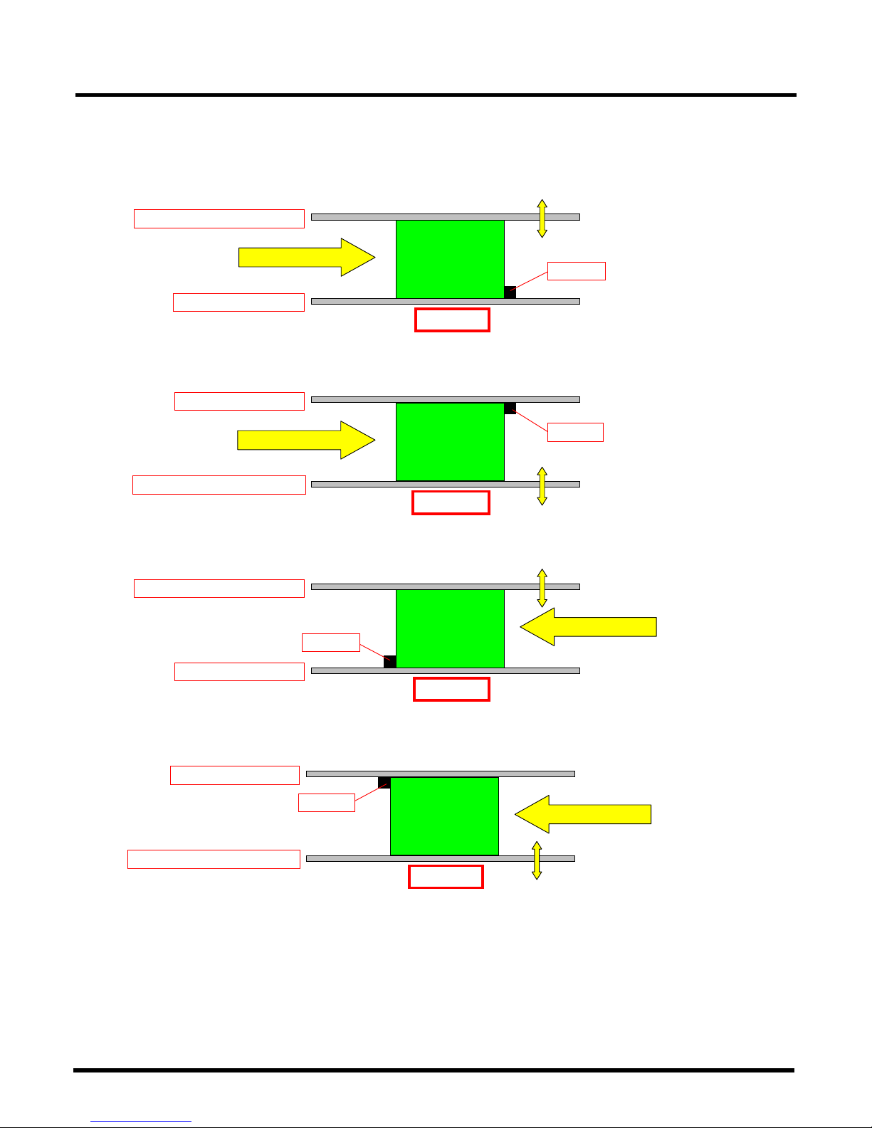
1.3.3 Board Flow Direction
The board flow direction and the board positioning reference can be changed optionally.
The reference of mount data can be set arbitrarily on PT.
Standard: Left-to-right flow, Front reference
Option: Left-to-right flow, Rear reference
Option: Right-to-left flow, Front reference
Option: Right-to-left flow, Rear reference
EJM4A-E-RMA01-A01-00
Board flow direction
Stopper
Width-adjustment conveyor
Reference conveyor
Front side
Board flow direction
Stopper
Width-adjustment conveyor
Reference conveyor
Front side
Board flow direction
Stopper
Width-adjustment conveyor
Reference conveyor
Front side
Board flow direction
Stopper
Width-adjustment conveyor
Reference conveyor
Front side
Page 15
CM602-L
Reference Manual
1.3 Equipment Specifications
Page 1-15
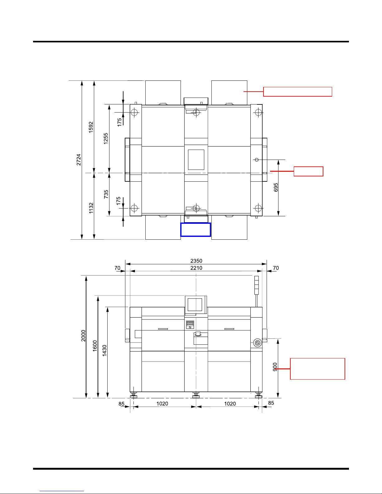
1.3.4 Outside Dimensions
(All dimensions in mm)
EJM4A-E-RMA01-A01-00
EJM4A-134E
Collectively changing truck
Reference
Board transport height
900
(Option: 950)
Front
Page 16
CM602-L
Reference Manual
1.4 Other Specifications
Page 1-16
1.4 Other Specifications
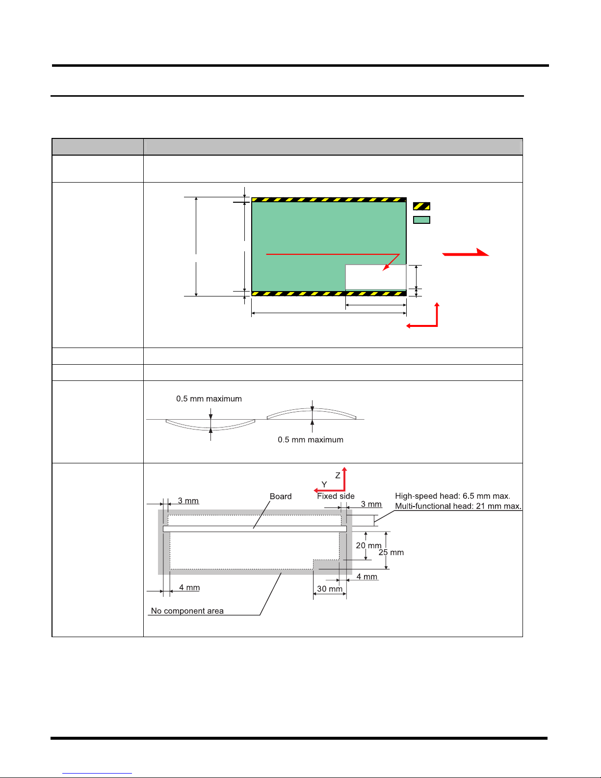
1.4.1 Applicable Board Specifications
(1/2)
Item Specifications
Available board
dimensions
Max.: 510 mm (L) × 460 mm (W) / Min.: 50 mm (L) × 50 mm (W)
Placement area
Board flow
4.5 mm
Y
X
20 mm
3 mm
3 mm
50 mm
50 mm to 510 mm
No cutout area
:No component area
50 mm
to 460 mm
44 mm
to 454 mm
:Placement area
Fixed side
EJM4A-114E
Board thickness
0.3 mm to 4.0 mm
Board mass
3.0 kg or under (after placement)
Allowable warp
accuracy
4X3C-218E
Cross section of board
Pre-placement board
state
EJM4A-113E
EJM4A-E-RMA01-A01-00
Page 17
CM602-L
Reference Manual
1.4 Other Specifications
Page 1-17
(2/2)
Item
Specifications
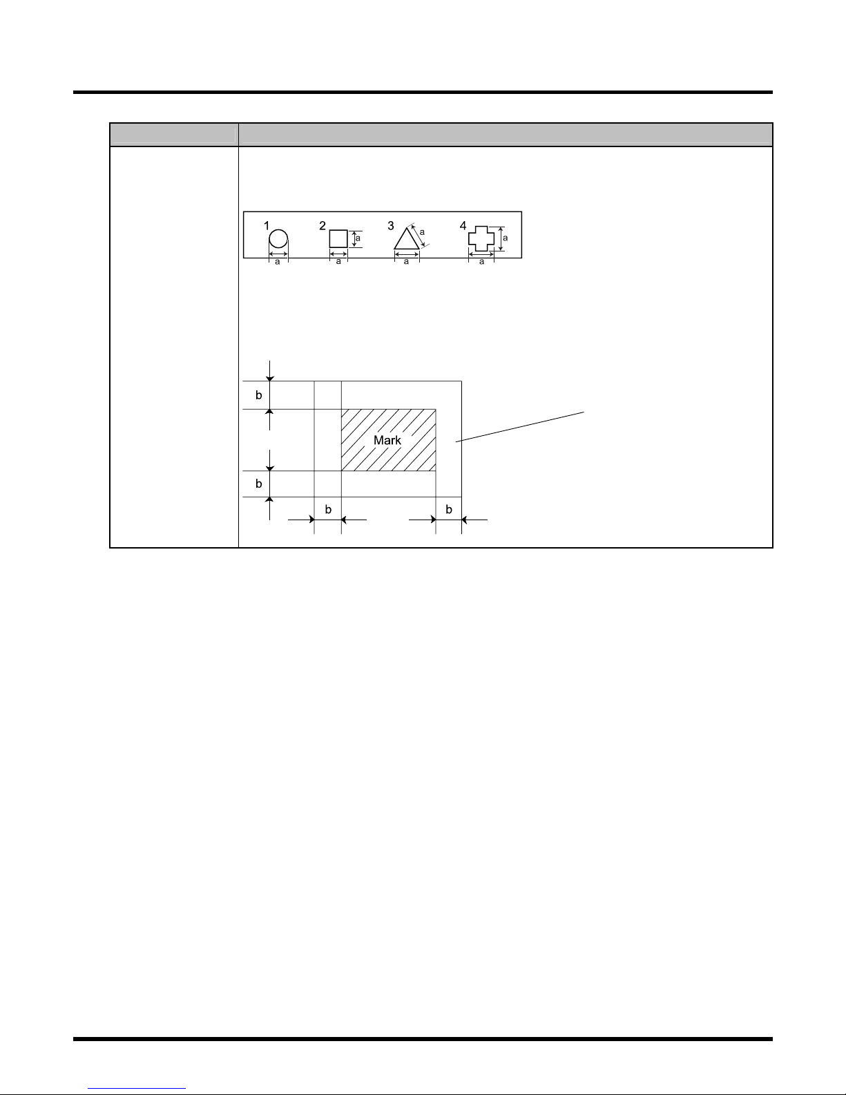
Examples of mark shape
Board recognition implements compensation through the use of the physical relationship
between recognition marks and a circuit pattern.
A fixed contrast is required between recognition marks and a board. (Binary-contrast image)
0.5 mm ≤ a ≤ 1.6 mm
EJM4A-115E
∗
The figure 3 above is a regular triangle.
Mark dimensions and background
The background of a mark requires the noninterference area—larger than certain
dimensions—outside the mark itself.
Board recognition
mark
EJM4A-116E
Noninterference area
b ≥ 0.2 mm
EJM4A-E-RMA01-A01-00
Page 18

CM602-L
Reference Manual
1.4 Other Specifications
Page 1-18
1.4.2 Installable Feeder Count
1. Intelligent feeder
Feed pitch (1 pitch = 4 mm)
Feeder
type
Tape
width
Type
Reel
diameter
∗
1
Installati
on
pitch
Max.
depth of
boss
Max
inst.
reel count
0.5 1 2 3 4 5 6 7 8 9 10 11 12 13 14
Small 21 mm 216
8 mm
∗
2
double T/F
8 mm
Paper
Embossed
Large 21 mm
3
108
z z
Small 21 mm
8 mm
single T/F
8 mm
Paper
Embossed
Large 21 mm
3 108
z z
Small 21 mm 15 108
12 mm
Embossed
Large 21 mm 15 108
12 mm
16 mm
shared T/F
16 mm
Embossed
Large 21 mm 15
108
∗
3
z z z z
24 mm
Embossed
Large 42 mm 15 52
24 mm
32 mm
shared T/F
32 mm
Embossed
Large 42 mm 15 52
z z z z z z z z
15
44 mm
Embossed
Large 63 mm
21
∗
5
36
15
44 mm
56 mm
shared T/F
56 mm
Embossed
Large 63 mm
21
∗
5
36
z z z z z z z z z z z z z
15
72 mm T/F
72 mm
Embossed
Large 84 mm
21
∗
5
24
z z z z z z z z z z z z z
88 mm T/F
∗
4
88 mm
Embossed
Large 105 mm
21
∗
5
20
z z z z z z z z z z z z z
104 mm T/F
∗
4
104 mm
Embossed
Large 126 mm
21
∗
5
16
z z z z z z z z z z z z z
32 mm
adhesive
T/F
∗6∗
7
32 mm
Adhesive
Large 63 mm 2.8 36 3 (12 mm)
∗
1
:
Reel diameter: Small reel =
φ
178 mm, Large reel =
φ
178 mm to
φ
382 mm
∗
2
:
For the 8 mm double tape feeder, two small reels or each one of small and large reels can be set.
∗
3
:
Depending on the reel width, the maximum installation count may decrease.
∗
4
:
The 88 mm and 104 mm types are always equipped with a joint detection sensor.
∗
5
:
To use the maximum depth of boss (21 mm), the 21 mm thickness-ready cutting unit (option) and the 21
mm cutting-ready changing truck (option) are required.
∗
6
:
The adhesive tape feeder is always equipped with no joint detection sensor.
∗
7
:
To use the adhesive tape feeder, the machine needs as many optional bulk/adhesive feeder-support units
(1 set/1 table) as required.
NOTICE
The following conditions are necessary for using the gang feed function in right and
left lanes of double tape feeder, for the high-speed head (12 nozzles).
•
Software incorporated in the double tape feeder: Version 5.00 or later
•
Software incorporated in the collectively changing truck: Version 1.20 or later
EJM4A-E-RMA01-A01-01
Page 19
CM602-L
Reference Manual
1.4 Other Specifications
Page 1-19
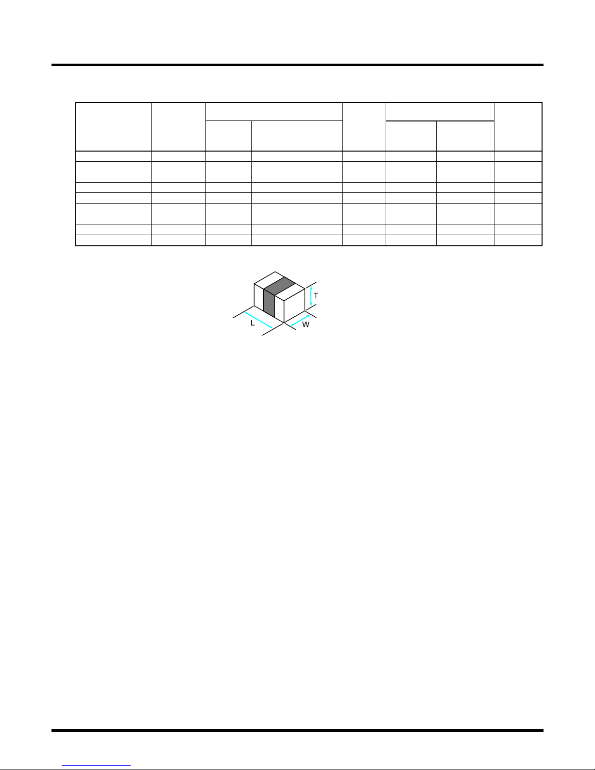
2. Bulk feeder
Chip dimensions (in mm)
Chip aligning time (in s)
Feeder type
Target chip
type
L
W
T
Installation
pitch
(in mm)
Per chip
Per feeder
Chip
alignment
count
Min. in
parentheses
1005C B/F
1005C
1.0 ±0.05 0.5 ±0.05 0.5 ±0.05
21 0.5 88.5 177(168)
1005R B/F
1005R
1.0 ±0.05 0.5 +0.05
0.5 −0.02
0.35 ±0.05
21 2 354 177(168)
1608C B/F
1608C
1.6 ±0.1 0.8 ±0.1 0.8 ±0.1
21 0.6 66 110(103)
1608R B/F
1608R
1.6 ±0.1 0.8 ±0.1 0.45 ±0.1
21 2 220 110(103)
2012C, t=0.6 B/F 2012C, t=0.6
2.0 ±0.1 1.25 ±0.1 0.6 ±0.1
21 2.5 220 88(83)
2012C, t=0.85 B/F 2012C, t=0.85
2.0 ±0.1 1.25 ±0.1 0.85 ±0.1
21 2.5 220 88(83)
2012C, t=1.25 B/F 2012C, t=1.25
2.0 ±0.1 1.25 ±0.1 1.25 ±0.1
21 1.5 132 88(83)
2012R B/F
2012R
2.0 ±0.1 1.25 ±0.1 0.55 ±0.1
21 2.5 220 88(83)
EJM4A-E-RMA01-A01-00
EJM4A-401E
Page 20
CM602-L
Reference Manual
1.4 Other Specifications
Page 1-20
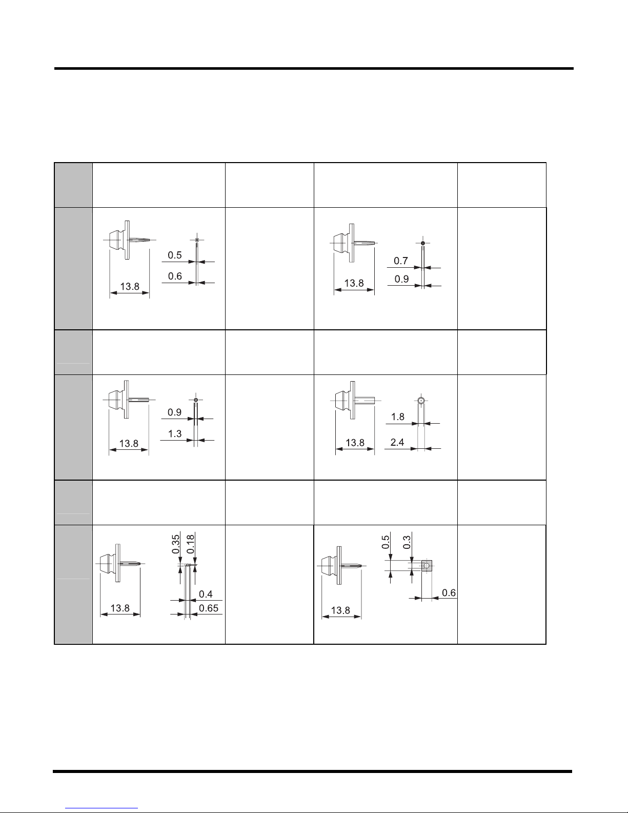
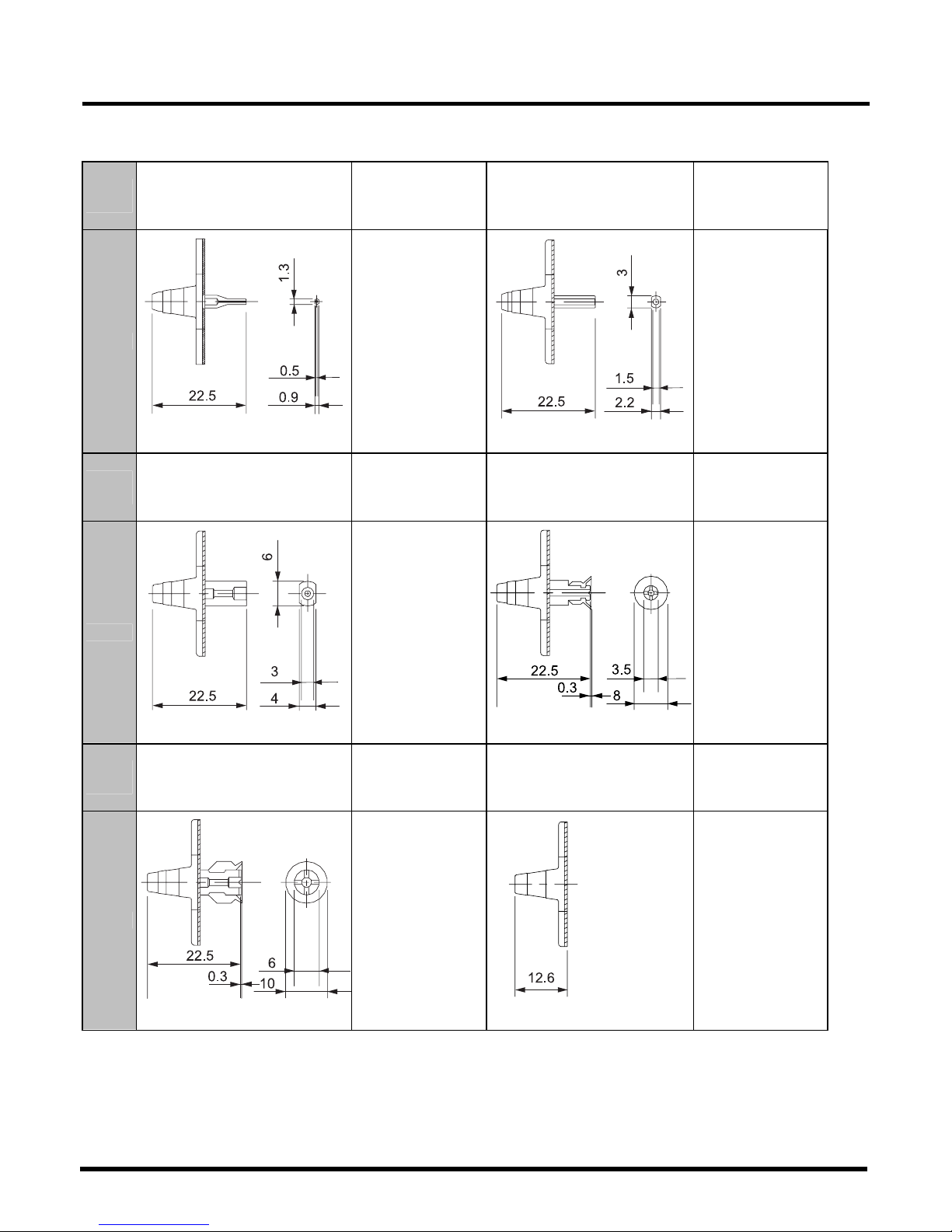
1.4.3 Nozzle Specifications
This machine is equipped with the standard nozzles in each head, supporting many different
components.
For high-speed head (12 nozzles): 6 types
(All dimensions in mm)
Nozzle
No.
110S
Target components
(Representative
examples)
115AS
Target components
(Representative
examples)
Shape
EJM4A-418E
1005R, C
1608, C
EJM4A-419E
1608R, C
2012R, C
SS-Mini Tr, Di
S-Mini Tr, Di
Nozzle
No.
120S
Target components
(Representative
examples)
130S
Target components
(Representative
examples)
Shape
EJM4A-420E
2012R, C
3216R, C
S-Mini Tr, Di
Mini Tr, Di
EJM4A-421E
3225R, C
4532R, C
TAN-X, B, C
Al electrolytic - A, B
Nozzle
No.
205S
Target components
(Representative
examples)
206AS
Target components
(Representative
examples)
Shape
EJM4A-416E
0603R, C
EJM4A-417E
0603R, C
1005R, C
EJM4A-E-RMA01-A01-01
Page 21

CM602-L
Reference Manual
1.4 Other Specifications
Page 1-21
Nozzle layout for high-speed head (12 nozzles)
Twelve pieces of nozzles (110S, 115AS, 120S, 130S, 205S, and 206AS shown in the previous
page), which support the components measuring 7.3 mm or less from one corner to the opposite
corner, can be attached.
Nozzle layout and fully attached nozzle count for high-speed head (12 nozzles) (figures seen
from above)
∗
For the high-speed head (12 nozzles), only the six types of nozzles shown in the previous page
are available.
EJM4A-156E
EJM4A-E-RMA01-A01-01
Page 22
CM602-L
Reference Manual
1.4 Other Specifications
Page 1-22
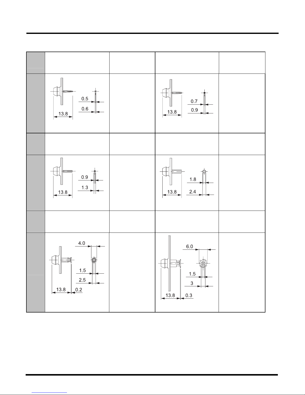
For high-speed head (8 nozzles): 9 types
(All dimensions in mm)
Nozzle
No.
110
Target components
(Representative
examples)
115A
Target components
(Representative
examples)
Shape
444C-003E
1005R, C
1608, C
444C-004E
1608R, C
2012R, C
SS-Mini Tr, Di
S-Mini Tr, Di
Nozzle
No.
120
Target components
(Representative
examples)
130
Target components
(Representative
examples)
Shape
444C-005E
2012R, C
3216R, C
S-Mini Tr, Di
Mini Tr, Di
444C-006E
3225R, C
4532R, C
TAN-X, B, C, D
Al electrolytic - A, B,
C
Nozzle
No.
140
Target components
(Representative
examples)
450
Target components
(Representative
examples)
Shape
444C-007E
TAN-D
Al electrolytic - D
SOP, SOJ
PLCC, CSP
444C-008E
SOP, QFP
PLCC, BGA
18 mm × 18 mm
EJM4A-E-RMA01-A01-01
to
Page 23
CM602-L
Reference Manual
1.4 Other Specifications
Page 1-23
(All dimensions in mm)
Nozzle
No.
460
Target components
(Representative
examples)
205
Target components
(Representative
examples)
Shape
4X3C-202E
SOP, QFP
PLCC, BGA
24 mm × 24 mm
EJM4A-402E
0603R, C
Nozzle
No.
206A
Target components
(Representative
examples)
Shape
4X3C-209E
0603R, C
1005R, C
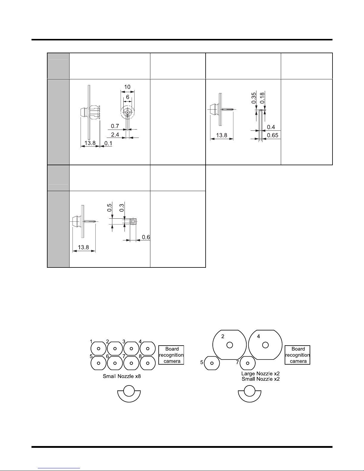
Nozzle layout for high-speed head (8 nozzles)
Small nozzles (110, 115A, 120, 130, 140, 205, and 206A shown in the above tables), which
support the components measuring 12 mm or less from one corner to the opposite corner, can
be attached to all the heads.
Large nozzles (450 and 460 shown in the above tables), which support the components
measuring more than 12 mm from one corner to the opposite corner, can be attached to the
head No. 2 and the head No. 4. At the same time, small nozzles can also be attached to the
head No. 5 and the head No. 7.
Nozzle layout and fully attached nozzle count for high-speed head (8 nozzles) (figures seen from
above)
∗
For the high-speed head (8 nozzles), only the nine types of nozzles shown above are available.
EJM4A-E-RMA01-A01-01
EJM4A-117E
to
Page 24
CM602-L
Reference Manual
1.4 Other Specifications
Page 1-24
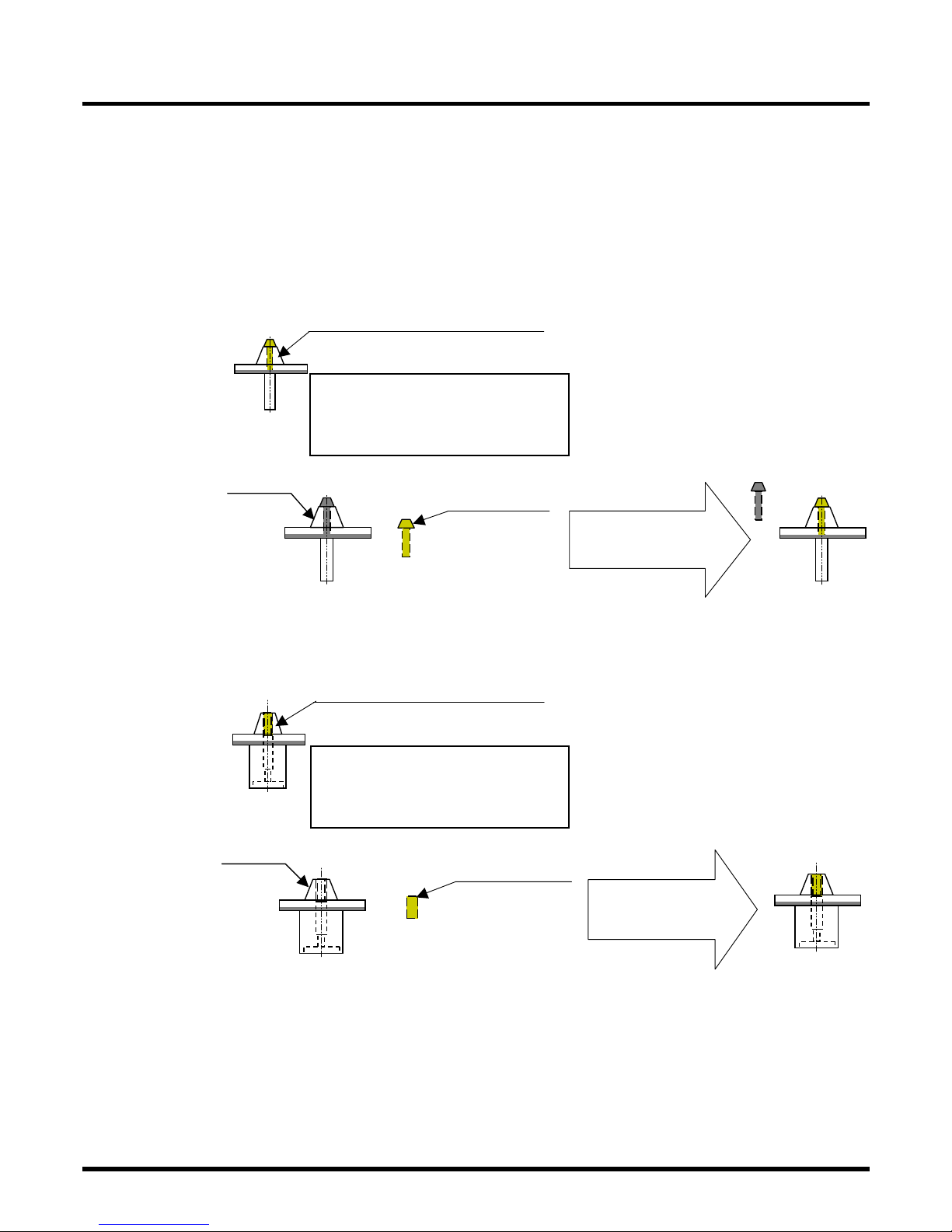
For multi-functional head: 6 types
(All dimensions in mm)
Nozzle
No.
1001
Target components
(Representative
examples)
1002
Target components
(Representative
examples)
Shape
4X3C-203E
1005R, C
1608R, C
2012R, C
SS-Mini Tr, Di
S-Mini Tr, Di
Mini Tr, Di
4X3C-204E
3216R, C
4532R, C
TAN-X, B, C, D
Al electrolytic - A,
B, C
Nozzle
No.
1003
Target components
(Representative
examples)
1004
Target components
(Representative
examples)
Shape
4X3C-205E
Al electrolytic - D,
E, F
SOP
SOJ
PLCC
BGA
CSP
EJM4A-136E
SOP
SOJ
QFP
PLCC
BGA
Nozzle
No.
1005
Target components
(Representative
examples)
1006
Target components
(Representative
examples)
Shape
EJM4A-135E
SOJ
QFP
PLCC
BGA
4X3C-208E
This is a nozzle
(a reflector) to
be attached to
the head not in
use for pickup,
depending on
the combination
of components
to be picked up.
It enhances the
recognition
stability of the
head in pickup.
<Application>
・
For the components
measuring 23 mm ×
23 mm to 38 mm ×
38 mm, it is attached
to the center of the
three nozzle
positions.
・
For the components
measuring 38 mm ×
38 mm or more, it is
attached to both the
ends of the three
nozzle positions.
EJM4A-E-RMA01-A01-01
Page 25
CM602-L
Reference Manual
1.4 Other Specifications
Page 1-25
1.4.4 Compatibility among Nozzles
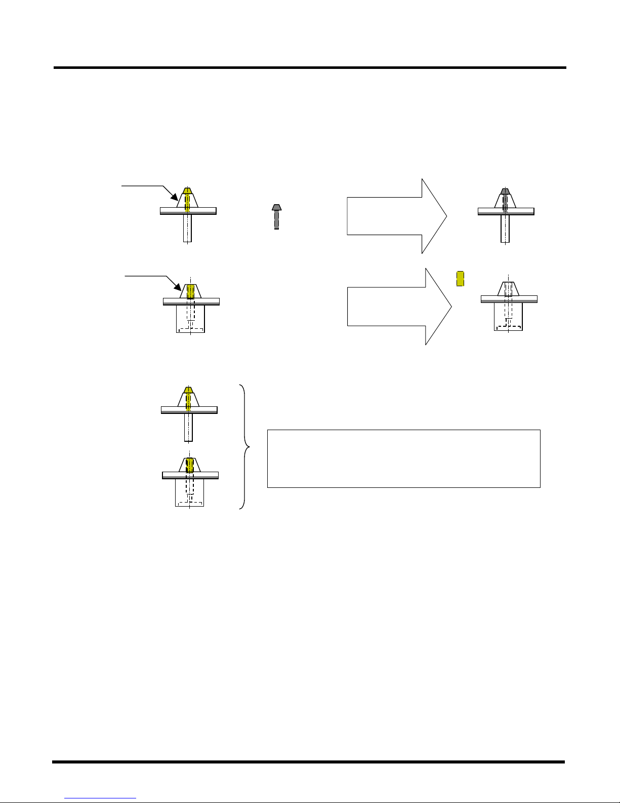
The following conditions are required for compatibility between the nozzles for the CM602
multi-functional head and those for the former models (CM301/CM20/CM120/CM100).
1. When wishing to use the nozzles for the former models on CM602, you need to
attach CM401/CM402/CM602-specific orifices to them.
In this case, detach/attach the orifices seeing below.
a. Divided-type nozzles (1001, 1002 nozzles)
CM401/CM402/CM602-specific orifice
Plated:
CM401/CM402/CM602-ready
SUS:
CM401/CM402/CM602-unready
Current nozzle
Dedicated orifice
(Bolt type)
+
Product number:
KXFB03KNA00
CM401/CM402/CM602-ready
(Orifice change)
b. Integral-type nozzles (1003, 1004, 1005,
special nozzles)
CM401/CM402/CM602-specific orifice
With orifice:
CM401/CM402/CM602-ready
Without orifice:
CM401/CM402/CM602-unready
Current nozzle
Dedicated orifice
(Setting-screw type)
+
Product number:
KXFB03KPA00
CM401/CM402/CM602
-ready
(Orifice attach)
EJM4A-E-RMA01-A01-01
Page 26
CM602-L
Reference Manual
1.4 Other Specifications
Page 1-26
2. When wishing to use the nozzles for CM401/CM402/CM602 on the former models,
you need to detach CM401/CM402/CM602-specific orifices from them (for using
some nozzles) or change the settings of a vacuum sensor (for using all nozzles).
In this case, one of the following two setup (handling) procedures is required. See below.
a. Detaching CM401/CM402/CM602-specific orifices (when using some nozzles)
CM401/CM402/CM602-ready nozzle
+
Former
model-ready
(Orifice change)
CM401/CM402/CM602-ready nozzle
Former model-ready
(Orifice detach)
b. Changing the settings of vacuum sensor (when using all nozzles)
∗
In this case, all the nozzles to be used must be intended for
CM401/CM402/CM602.
To use CM401/CM402/CM602 nozzles as they are on the
former model, you need to change the settings of vacuum
sensor.
(For the setting procedures, see the following pages,
“Setting procedures of vacuum sensor.”)
EJM4A-E-RMA01-A01-01
Page 27
CM602-L
Reference Manual
1.4 Other Specifications
Page 1-27
Setting procedures of vacuum sensor (Example: For CM301)
Make the setting on each beam. (Two indicators need to be set.)
<Reference vacuum uptake value check>
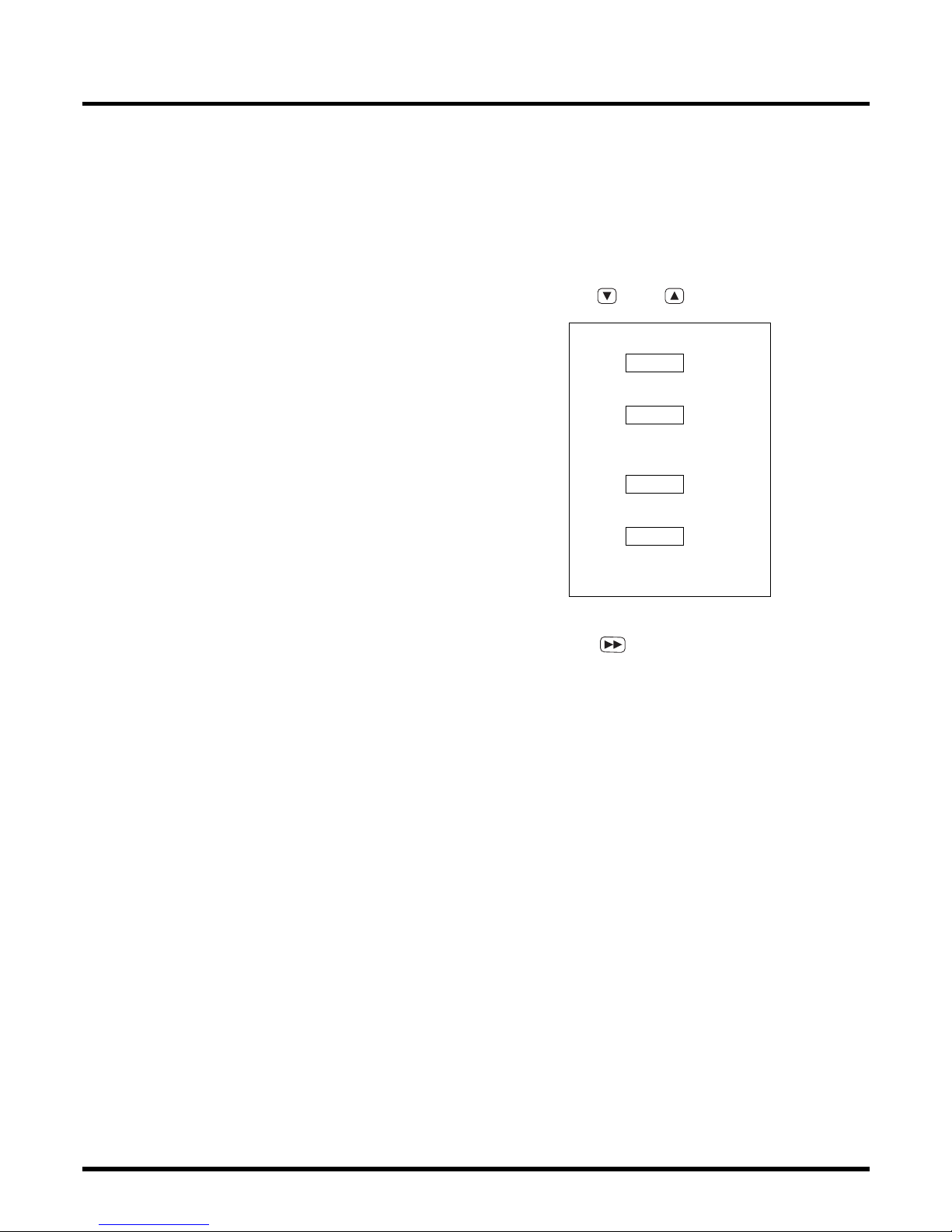
1.
Attach 1003 nozzles to each head.
∗
Use the nozzles without orifices.
2.
Select the channels (1ch, 3ch) to be set,
using
and
keys.
Each channel’s function
1ch
Head A
Nozzle-off detection
2ch
Head A
Pickup miss
detection
3ch
Head B
Nozzle-off detection
4ch
Head B
Pickup miss
detection
3.
Press
for three seconds or more.
•
When it is reset, 0 is indicated.
•
It is carried out with a vacuum OFF.
4.
Turn ON a vacuum in the output check.
5.
Read the indication on the vacuum
sensor.
EJM4A-E-RMA01-A01-00
Page 28
CM602-L
Reference Manual
1.4 Other Specifications
Page 1-28
<Vacuum sensor setting procedure>
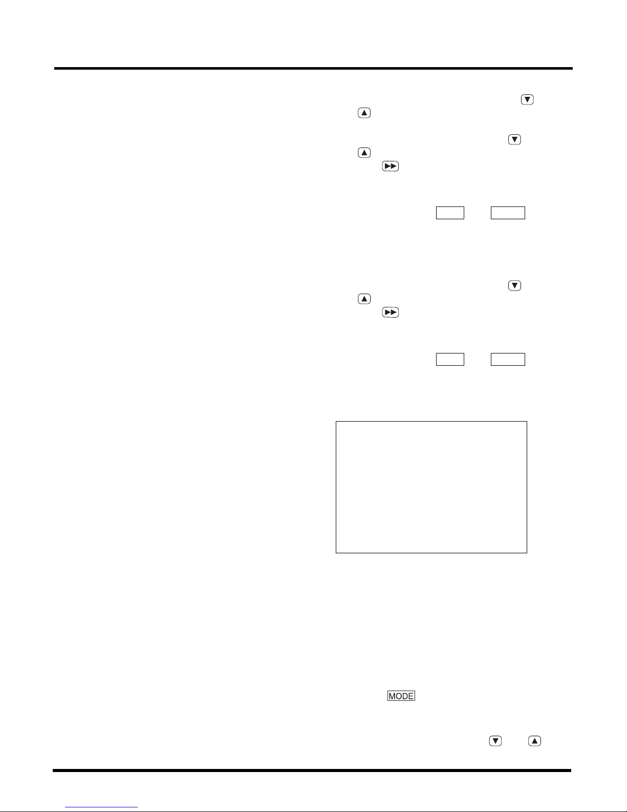
1.
Select the channels to be set, using
and
keys.
2.
Change the pressure value using
and
keys, and accept your entry by
pressing
.
•
This step covers the setting of pressure value
(H− ).
Indication example:
H−1
⇔
−
46.0
Alternately
∗
For setting values, refer to the specifications
(the setting values of vacuum sensor below).
3.
Change the pressure value using
and
keys, and accept your entry by
pressing
.
•
This step covers the setting of pressure value
(h− ).
Indication example:
h−1
⇔
−
1.0
Alternately
∗
For setting values, refer to the specifications
(the setting values of vacuum sensor below).
[Setting values of vacuum sensor]
H−1 = P0 + 1.0
h−1 = −1.0
H−2 = −10 (Original setting value: −20)
h−2 = 0
H−3 = P0 + 1.0
h−3 = −1.0
H−4 = −10 (Original setting value: −20)
h−4 = 0
P0: Vacuum pressure of 1003 nozzle
Setting procedures of vacuum sensor (Example: For CM20/CM120/CM100)
Make the setting on each head. (Three indicators need to be set.)
1.
Change the settings of pressure values.
Setting value P3 (Original setting value:
−
149)
⇒ −
74
Setting value P4 (Original setting value:
−
150)
⇒ −75
(How to check)
Pressing
toggles an indication in order
(P−1, …P−5), alternating with the setting value.
(How to change the settings)
Change the setting values, using
and
keys.
EJM4A-E-RMA01-A01-00
 Loading...